毕业设计(雨辰)高层建筑消防救生装置总体设计及圆锥齿轮减速器设计【全套图纸】
消防工程毕业设计

本建筑为一酒店,属于二类高层建筑。
地上部分十三层,地下部分一层,主体建筑高度为43.5米。
负一层为地下车库。
本说明书涉及该建筑的自动报警系统和消防泵房设计。
自动报警系统:本建筑为二级保护对象,选择火灾自动报警控制系统的模式为集中报警控制系统。
每一楼层划分为一个报警区域,一个独立套房或走道划分为一个探测区域。
每一楼层设置感烟探测器,感温探测器,区域报警控制器,手动报警按钮,声光报警器等。
火灾自动报警控制器设置在消防控制室(保安室)。
消防泵房:泵房应设置两组泵:消火栓系统和自动喷水灭火系统各设一组,每组泵一用一备,其中备用消防水泵的工作能力不应小于其中最大一台消防工作泵。
与消防泵配套的还有湿式报警阀,给水管网 , 消防水池。
消防水池的大小设计应根据消火栓系统和自动喷水灭火系统的用水量要求设计。
对于管网系统,一组消防泵,吸水管不应少于两条,当其中一条损坏或检修时,其余吸水管应仍能通过全部水量,消防泵房应设不少于两条供水管与环状管网连接,当其中一条出水管检修时,其他的出水管应仍能供应全部用水量。
关键字:消防泵房,消防水池,自动报警系统,感烟探测器,感温探测器This building is a hotel, which belong to the second class high-rise building. There are 13 layers on the ground and one layer underground, the height of the main building is 43.5 meter. The layer underground is a garage.This manual is about the design of the building's automatic alarm system and fire pump room.The automatic alarm system: the building level should set to level 2 whose automatic fire alarm control system model is the concentrated alarm control system. Each floor is divided into a warning area , each independent room or layer is divided into a detection area. There are the feeling smoke detectors the temperature detector, the fire shows dish , the fire radio, the manual alarm button and so on each floor . Automatic fire alarm controller is setted on fire control room (security room).Fire pump room : the pump room shall set up two group of pump, one set is for the fire hydrant system, the second set is for automatic sprinkler system. The fire water system should set up two fire hydrant pumps (one is for prepare , whose working ability should be not less than the biggest fire control work pump) . What matching of the fire hydrant pump is wet alarm valves,water distribution network, fire pool, the water pump for engagement . The size of the fire-fighting pool should be designed basing on the design requirements of the water consumption of the fire hydrant system and automatic sprinkler system . For the pipeline network system,the suction pipe of a team of fire pump should not be less than two . when one of the damage is for maintenance, the rest of the suction pipe should be still can pass all water. Fire pump room should set of not less than two pipes which are connecting with the pipe network connection ring. When one of the conduit is overhauling, the other of the pipe should still supply the entire water consumption.[Keywords]: fire pump room , fire-fighting , automatic alarm control system, smoke feeling detector, temperature detector.某酒店自动消防系统设计1引言随着社会的发展, 高层建筑在我国日益增多, 而由于高层建筑本身的特性, 火灾扑灭难度非常大, 常造成重大损失, 为了防止和减少火灾危害,保护人身和财产安全,自动消防系统已经成为必不可少的设施。
高层建筑急救逃生梯装置设计与 Finite Element 分析说明书
International Conference on Manufacturing Engineering and Intelligent Materials (ICMEIM 2017)The Design and Finite Element Analysis of Emergency Escape Ladderfor High-Rise BuildingYu-jing He a, Ya-dong Tang b and He Li c*The Agriculture University of Henan, College of Machinery and Electronic Engineering, Zhengzhou,China, 450002a******************;c*****************Corresponding authorKeywords: Security, Emergency Escape Ladder, Finite Element Analysis, ANSYS.Abstract. An emergency escape ladder which is applied in emergency, for rescue and escaping is designed in this paper to meet the urge needs in modern society. As the major bearing part of the whole ladder, the ladder assembly’s rigidity and strength determines the safety and reliable running of the ladder. This paper used the finite element analysis software ANSYS for nonlinear mechanics analysis of the first-section ladder, obtained the distribution diagram stress and strain, gave analysis results of the rigidity and strength, and provided an improved method and recommendations. IntroductionWith the industrialization and urban development, the casualties and direct economic loss by fire has presented a corresponding increased trend. In particular, the progressively increased modern urban high-rise building and larger density of building make the fire rescue in higher buildings more and more difficult. There are few relevant domestic researches at present, and the similar domestic instruments are not mature enough, but at the same time, the society has put forward increasingly high requirements on the rescue devices in high-rise buildings. For this reason, this paper designed a kind of emergency escape ladder. As set above the balcony, it is usually in a folded state, but opened under dangerous situation to help trapped men fall to earth quickly. This ladder can be used for self rescue of both trapped men and firefighters. Again, it would not subject to storey height, for which the precious time is saved. The main stress should be assumed by the ladder assembly, so enough rigidity and strength needs to be satisfied. The traditional strength calculation mainly employs the material mechanics method and selects larger security coefficient to guarantee the rigidity of ladder assembly [1]. With the development of CAE technology, employing the finite element analysis can calculate the stress and strain of each unit more accurately. In this way, the stress and strain of each unit can be clearly observed and the unreasonable then can be timely found out and thus provide the basis for rational design of ladder assembly. The details are shown as below.Integral Analysis and Operating Principle Introduction of the LadderThe integral structure of this emergency escape ladder for high-rise building can be seen in Figure1,mainly including three sections of the ladder, rescure pedal, screw, sliding block, etc. After starting the power section of automatic rescue ladder (motor) by remote control device, the motor makes the sliding block slide to the right under the effect of screw through the drive part (bevel gear, screw). In this way, the emergency escape ladder would be initiated, and the second and third ladder would be rapidly deployed under its own weight. Again, a good join with the next storey would be achieved to complete the stretching link of automatic rescue ladder. When you need to pack up the ladder tore duce the occupied space, you can start the motor by remote control device, pull up rope around the rope sheave, and tuck up the ladder from bottom to top, wherein the folding process is rather opposite to the deploying process. Finally, the ladder should be folded neatly beneath the pedal and wholly complete the folding process.The external forces suffered by the ladder are: horizontal pressure force by the wall, support force by the ground, static friction force by the ground hindering the movement trend, and the gravity by the man who stands on the ladder [2]. The internal forces suffered by the ladder are: force of friction between the wire rope and the ladder, and the tensile force. This paper then took the first-section ladder as an example and adopted finite element analysis software ANSYS for nonlinear mechanics analysis of the first-section ladder.FEA of First-Section Ladder Establishment of Geometric ModelIn the finite element analysis, the modeling precision of finite element model plays a great rule in the analysis result, and the modeling workload sometimes accounts for over 80% of the total. For this ground, the model quality even determines the application value and the guiding practice of analysis result [3]. The first-section ladder employs the modeling method that is from bottom to top and directly finish the modeling of parts for the simplified model in ANSYS [4]. Structural AnalysisThe model of this ladder can be seen in Figure 2. The actual ladder assembly is mainly made up of two rectangular steel tubes, which are connected by three beams. There are two rigidity ears on the steel, which connects to the upper diaphragm of the tripod. The parameters of the rectangular steel tube are shown in Table 1.Theoretical Weight Calculate Formula of Steel PipeW= (length of side + length of side)×2×wall thickness ×0.00785×lengthTable 1, Part Parameters of the Rectangular Steel Tube (GB/T3094-2000)length of sidewall thicknessarea of sectiontheoretical weight inertia moment section modulus ⁄㎜ ⁄㎜ ⁄㎝2 ⁄㎏/M ⁄㎝3 ⁄㎝4 40 5 6.98 5.48 16.56 7.87 60510.588.3054.5718.19Establishment and Analysis of Finite Element Model Analysis and Selection of Element TypeIn this section of ladder, profiles (beam column, etc.) materials are mainly involved. Based on the characteristics of loading and units, this paper directly used the defined material properties for finite element modeling of in the finite element calculation.Solid45 unit is used to construct 3D solid structure, units are defined by the eight nodes, and each node has the three degrees of translation freedom along the direction of the xyz. An unit has plasticity, creep, expansion, stress intensification, large deformation and strain capacity, so Solid45 unit is selected for discrete.The structure only has the bearing connection form, which is mainly the compression. The simplified model could be regardless of the rectangular steel tube, but to define all by cuboid entitywithout bolt hole, as shown in Figure 3.Theladdermaterials are 0Cr18Ni9 stainless steel (nickel-chrome steel, alloy steel), elasticity modulus E=2.06×10¹¹Pa, the Poisson's ratio µ=0.3, shear modulus G=7.938×10¹⁰Pa, strength of extension σb ≧520Mpa, offset yield strength σ0.2≧205Mpa, elongation rate σ5≧40%, reduction rate of area Ψ≧60%. Through the properties of the defined materials, the stress-strain curve of the materials can be obtained, as shown in Figure 4. Grid Divisionsides are welded together, wherein the weld is the whole contacting length. The weld is not considered in order to simplify the mesh partition grid. In the process of grid division, this paper used solid45 unit and triangular elements, while for the highest precision, the free grid is selected. Through the above analysis, the finite element model established for the first-section ladder is shown in Figure 5. After the grid division, there are totally 2169 nodes and 7748 units.Setting Analysis Type and Applying Constraint ConditionsThe transient dynamic analysis is a means to determine the dynamic response of time-dependent load by structure. It can analysis time-dependent displacement, strain, stress and force under random combination of the static load, transient load and harmonic load [5]. The ladder stress is time-dependent, so this paper set the analysis type as transient and adopted FULL method [6].The constraint of the first-section ladder is made by the upper hinges and hinges at the two ears. In the finite element model, it can be simplified: use 6DOF constraining the upper two arc surfaces for simulation.Solution of Finite Element ModelThe ladder is actually calculated to accommodate 2 people, the weight of each one is calculated as 75 (735.5 N), and considering the dynamic load coefficient of 1.35, then: the ladder beam load P1 =735.5 2, 1.35 = 1985.85 N, the force on the model is reduced to 300 N, density of 7.93 g /㎝³is 0Cr18Ni9, the quality of each ladder model is calculated about 2kg, th bottom of first-section ladder for each side is calculated as 2kg, which suffered from the pulling force of the lower ladders. Standing on the ladder beams has a process, thus this paper used the load steps for load calculationand analysis.First Load Step SolutionThis paper opened the configuration window of analysis and solution option, set the Analysis Option in the Basic Tab as Small Displacement Transient, Time at end of loadstep as 0.04, closed the Automatic Time Stepping, set the substeps of 30 and printout as Every Substep for basic solution result, and saved the node solution result in each substep. This paper then set the load loading method as Stepped Loading in Transient Tab [4]. The solution is shown in Figure 6. Second Load Step SolutionThis paper opened the configuration window of analysis and solution option, set the Time at end of loadstep as 0.14 and substeps of 30, printout the basic solution result, wherein the frequency is Every 5th Substeps. The solution is shown in Figure 7. Analysis of Finite Element ModelThis paper made finite element analysis for first-section ladder, wherein the stress unit is Pa and displacement unit is m. The output stress is von Mises stress, which is an equivalent stress calculated by the fourth strength theory calculation. The vector sum (contour map of displacement) displacement shown is the total displacement of the node. When the load is distributed evenly, the finite element analysis results of ladder beam and aberration nephogram can be seen in Figure 8, wherein MX in Figure 8a and b respectively represent maximum displacement and maximum stress location.According to the physical equation in the mechanics, ANSYS can be used to solve the stress component inside of the unit by the strain.⎪⎭⎪⎬⎫⎪⎩⎪⎨⎧⎥⎥⎥⎦⎤⎢⎢⎢⎢⎣⎡--=⎪⎭⎪⎬⎫⎪⎩⎪⎨⎧=Z Y X Z Y X E εεεμμμμσσσσ210001011}{2Where in, σx,σy,σz is normal stresses on the direction of x, y, z, unit: MPa;E elasticity modulus of materials, unit: MPa;μPoisson's ratio of materialsεχ,εy,εz strains on the direction of x, y, zIt can be seen from Figure 8a that, the largest displacement is situated in the middle part of the beam, whose value is 3.33×10⁻⁵m; it can be seen from Figure 8b that, the largest stress is situated between the both sides of beam and box iron welds, whose value is 3.5×10⁴ Pa.Conclusions and Design RecommendationsThrough the finite element analysis for the rigidity of the first-section ladder, the following conclusions can be obtained:(1) The ladder rigidity and strength satisfy the design requirements;(2) The stresses inside of the ladder are not distributed evenly, the welding part on both sides of the beam has relatively large stress, reflecting as local concentration and local distribution. The amplitude change of the beam stress is big, other parts of the stress level are low, and the intensity of surplus is big, providing a theoretical basis for ladder design optimization and research. Therefore, the design recommendations are given as below:(1) To improve the stress at the stress peak value by local structural optimization, such as, layinga stiffener on both sides of the beam, optimizing the welding quality or proper increase of steel strength;(2) To remain certain space for rigidity and strength on both sides of the steel frame, which can appropriately decrease the thickness of selected sectional material on both sides of the steel frame or adopt the steel materials with relatively small strength.References[1] Chuncheng WANG, Jingfeng YANG, Lijun WANG, et al, Finite Element Analysis and Optimal Design for Rolling Mill Rack, [J]. Machinery Design and Manufacture, 2009. 11, 11: 61-62.[2] Anlin ZHANG, Hede WANG, Suspension Composite Materials Ladderway [J].Coal Mine Design, 1995, 7: 17-21.[3] Xiaoming MA, Zhenqiang YAO, Finite Element Analysis of the Longspan Portal Framed Structure [J].Machinery Design and Research, 2008.12, 24(6): 72-74.[4] Lirong WAN, Hanzheng DAI, Xin ZHANG, Finite Element Analysis of the Hydraulic Powered Support Based on Cosmos/Works [J].Coal Mine Machinery,2009.10,30(10):1-3.[5] Fanping DENG, Self-Training Manual for ANSYS10.0 Finite Element Analysis [M]. Beijing: Posts and Telecom Press, 2007.1.[6] Xiangxin LIU, Xianyi MENG, ANSYS Basics and Application Program [M], Beijing: Science Press, 2006.3.[7] Jin DUAN, Dong NI, Guoye WANG, ANSYS 10.0 Structural Analysis: from Entry to Master, [M], Beijing:Weapon Industry Press,Beijing Kehai Electronic Press, 2006.10.[8] Guidong HUANG, Guanglie SHEN, Zhilin WEI, et al, Improvement for Finite Element Analysis of Automobile Frame [J], Machinery Design,2007.12,24(12):54-56.[9] Min HU, Jianghong CUI, Bide CAO, Finite Element Analysis for the ZF7200/18/35 Hydraulic Support [J], Coal Mine Machinery,2009.5,30(5):87-89.[10] Hongwen LIU,Material Mechanics [M]. Beijing: Higher Education Press, 2004.1.。
高楼火灾逃生装置设计(机械CAD图纸)

摘要在实际生活中有时会遇到紧急的意外情况,例如,火灾、地震等。
特别是在高楼居住和工作的人员,当发生火灾时,电梯往往不能使用,如何才能安全、快速地离开危险来到安全的地面一直以来都是人们十分关心的问题。
因此在高层居住和工作的人员都需要一种安全、可靠、安装方便、使用简单的高楼安全逃生装置。
高楼逃生设备中较成熟的有逃生伞和放火梯,其中逃生伞至少要求楼层在220米以上才能使用,而放火梯的使用高度在 15米以下,这大大的影响了它门得使用范围。
本课题研究的高楼自动安全降落逃生装置则适用于6-250米的高度范围,这正好可与逃生伞,放火梯优势互补。
该高楼逃生器结构简单,性能可靠,可以安装在高楼的外墙壁上,遇到紧急情况时就可以使用,具有较强的实用性和经济性。
关键词:高楼逃生器;自动减速;安全;可靠AbstractIn actual life sometimes meet urgent accidental situation, for example, fire, earthquake, etc. Especially in a high-rise residential and work of the staff, when when there is a fire, elevator often cannot use, how to safely and quickly left the ground of danger to safety has always been people are very concerned about the problem. So in a high-rise residential and work of the staff all need a safe, reliable, easy installation, use simple high-rise safely device. Tall buildings in the mature escape equipment umbrella and arson ladder have escape, including at least requirement floor escape umbrella in 220 meters above can use, and the use of fire ladder in 15 meters high. This greatly influenced it door may use scope, This topic research of building automatic safely escape device fits 6-250 meters height range, it just can escape umbrella, with complementary fire ladder. The towers of simple structure, escape is reliable performance and can be installed in a building exterior wall, when you meet the emergency can use, which has practicability and economy.Keywords: Tall escape manometers; Automatic slow; Security; Reliable目录摘要 (I)Abstract (I)1概述 (1)1.1高楼逃生器研究的意义 (1)1.2国内外高楼逃生器的主要类型 (1)1.3 本设计的创新部分及独特优势分析 (2)2高楼自动逃生器的设计 (2)2.1逃生器简介 (2)2.1.1 逃生器结构 (2)2.1.2 逃生器使用方法 (3)2.2逃生器加速环节设计 (3)2.2.1 计算传动装置的总传动比及分配各级传动比 (3)2.2.2 计算传动装置的运动和动力参数 (4)2.2.3 齿轮的设计与校核 (4)2.2.4 轴的功能和工作原理 (14)2.2.5 轴的结构设计特点 (14)2.2.6 轴的作用 (14)2.2.7 轴的类型 (15)2.2.8 轴按其承载情况分类:转轴和心轴和传动轴 (15)2.2.9 轴的材料选择 (15)2.2.10 轴的设计与校核 (15)2.3逃生器速度调节环节设计 (23)2.3.1 质量块的设计 (25)2.4逃生器多人循环环节设计 (26)2.5逃生器安全锁紧装置的设计 (27)结论 (28)参考文献 (29)致谢 (30)外文翻译 (31)1概述1.1高楼逃生器研究的意义在实际生活中有时会遇到紧急的意外情况。
大厦高层建筑排水消防系统设计书
大厦高层建筑排水消防系统设计书1.1设计题目xx大厦给水排水、消防设计。
1.2设计目的毕业设计是在本科生学完教学计划所规定的全部课程后进行的最重要的也是最后一个实践性教学环节。
通过毕业设计使学生自觉地树立精心设计的思想,理论联系实际的学风,掌握一般民用或工业建筑给排水工程和消防工程的设计程序、方法和步骤。
了解和熟悉本领域的新材料、新设备、新方法和新技术。
熟悉国家和地方的有关规定和技术措施,学会使用有关技术手册和设计资料,提高计算和绘图技能,提高对实际工程问题的分析和解决能力。
1.3设计围本次设计主要包括建筑部给水、排水、消防设计。
1.4原始资料1.4.1工程概况设计建筑物位于xx,是一栋以宾馆为主体含有商场的综合性高层建筑。
建筑物总高度65.2米,总面积为26481m2。
主楼是十五层建筑,一至四层为商场,-1层为地下室。
地下室设水泵房,空调机房,换热站和地下停车场,其面积为2511.6 m2,层高为4.2m;一至四层为商场,一二层层高为5.1m三四层层高为 4.8m,四、五层之间设计设备层。
五至十五层为宾馆,层高为 3.6m,其中五至十五层面积为12611 m2,屋顶为水箱间,层高为3.9m。
1.4.2土建资料该建筑的平、立、剖面图及建筑平面布置图:图纸主要有:1、地下室平面图1:100(比例同建筑图以下同)。
2、建筑首层平面图1:100。
3、建筑非标准层平面图,1:100。
4、建筑标准层平面图,1:100。
5、顶层平面图,1:100。
6、各立面图,1:100。
7、必要的剖面图,1:100。
8、卫生间大样图,1:100。
1.4.3城市给排水资料1、建筑所在地区2、建筑性质综合性住宅3、结构与基础类型框架结构,钢筋混凝土基础。
4、城市给水管网管径 600mm,管顶埋深 2.1m,城市可靠供水压力:300Kpa。
5、城市排水管网管径:1500mm,管底埋深:4.5m。
6、冰冻线深度:-1.69m。
7、地下水深:-2.5m。
高楼逃生器毕业设计说明书

课程设计论文报告(论文)题目:高楼逃生器摘要高楼逃生器是在火灾的发生过程中,为保证居住在高层的人员能安全的逃生而设计的机械装备。
本文对高楼逃生器从机构设计、机构间的受力分析等方面进行了详细的研究计算。
首先,为精确的精确控制逃生人员的下降速度,本机械采用了双重制动措施。
制动装置分别依靠人本身的重力和在下降过程中人员的操作来实现制动,从而实现了逃生人员下降速度的可控性。
通过制动装置的作用使得被困人员能安全快捷的逃生。
其次,为了保证制动的稳定性和可靠性,故选用了传统的摩擦制动途径。
并在研究过程中给出了相关机构详细的计算设计过程和图纸的详细标注。
再次,考虑到充分利用材料、延长寿命、降低成本以及本装置使用的一次性等因素,本装置省去了轴承采用了的轮盘直接与轴配合的结构。
根据以上的理论计算,对高楼逃生器进行了模拟实验,取得了比较满意的结果。
关键词逃生器机构制动装置AbstractTall-building escape device is a machinery that designed for ensure the people living in high could escape from the fire. In this paper,we study the machinery on the mechanical design, stress analysis and other aspects of inter-agency thoroughly.Firstly,in order to control the speed of descent precisely,the machinery break with the dual measures. Brakes are relying on people's own gravity and personnel control during descent to achieve the braking operation, enabling people to escape at a controllable speed. So people who were trapped can escape at a safe and efficient way.Secondly, in order to ensure the stability and reliability of the brake, so we select the traditional friction brake means. And in the course of the study relevant agencies are given the detailed design calculations and drawings in the detailed annotations.Thirdly, taking account of the full use of materials, prolonging the worklife, reducing costs and one-time use of this device and other factors, this device eliminates the use of the wheel bearing.According to the above theoretical calculations, were carried out on the rise building evacuation simulation, and achieved satisfactory resultsKeywords: Escape device machinery brake rigging目录摘要 (1)Abstract (2)第一章绪论 (5)1.1设计背景 (5)1.2 发展概况 (6)1.3设计的目的意义及基本思路 (6)1.3.1设计的目的意义 (6)1.3.2设计的基本思路 (6)第二章整体方案设计 (7)2.1整体方案的设计 (7)2.2装置的原理 (8)2.3装置的优点与不足 (9)2.3.1装置的优点 (9)2.3.2装置的不足 (10)第三章装置零部件设计 (10)3.1轴的设计 (10)3.1.1轴的概述 (10)3.1.2主轴的设计(参数及视图) (10)3.2轮盘设计 (13)3.2.1 轮盘的概述 (13)3.2.2轮盘的基本参数及视图 (13)3.3闸瓦的设计 (14)3.3.1闸瓦概述 (14)3.3.2闸瓦的基本参数及视图 (14)3.4其他零部件的设计 (15)第四章计算和验证 (19)4.1静力学平衡计算 (19)4.2绕绳计算 (20)4.3速度计算 (20)结束语 (23)参考文献 (24)致谢 (25)第一章绪论1.1设计背景随着社会的发展和科技的进步,高层建筑成为了人们工作和生活中不可或缺的部分。
一种高楼救生器的设计

(3 :7 — 8. E ) 523 2
[ ]Z a gYM.ag ZR l bly- ae e sii nls eil 9 hn Y n 。ei it bsd snivy a ayi o vhce a i tt sf
cmp nnswt o — oma ds b t npr ee J, tra oa o o et i n n n r l ir ui aa tr l I e t n h t i o m s Jn n i l
Ju ao A tm t e eh ooy2 0 1 ( )1 1 14 o rl f uo oi T cn lg ,0 9,0 2 :8 — 9 . n v
o at o i o pn n l] t a oa Jun f ei eSf y f u m b e m oe t J. e t nl ora o V h l a t o lc s I r i nn l c e ,
可 达 10 安 装方便 等优 点。其 工作 原理是利 用 多级 齿轮 实现增 速传动 , 0 m、 将人 体 下降 时的速 度传 递给
发电机并带动发电机转动发 出电能, 并通过功率热电阻转化成热能耗散 , 少势能向动能的转化 , 减 从而
实现高空缓降。 根据人体正常重量,确定采用三级增速齿轮 实现速度传递,设计计算 了 各级齿轮传动
s di hg reb i n o g a i d a o na a hna e cus ue i —i uli fr i tuer pdw dec ew e fr ocr. n h s dg s h hl t m n sp i
Ke r sRec ea p r t s M a n t a p n ; e h n c l e in; a a s iso y wo d : s u p a a u ; g ei d m i g M c a ia sg Ge rt n m sin c d r
【毕业设计】-二级直齿圆柱齿轮减速器的设计(含全套CAD图纸)
【毕业设计】-二级直齿圆柱齿轮减速器的设计(含全套CAD图纸)xxxx大学毕业设计说明书学生姓名:学号:学院:专业:题目:二级直齿圆柱齿轮减速器的设计指导教师:职称:职称:20** 年12 月5 日目录1引言. . . . . . . . . . . . . . . . . . . . . . . . . . . . . . . . . . . . . . . . . . . . . . . . . . . . . . . . . . . . . . . 12传动装置总体设计. . . . . . . . . . . . . . . . . . . . . . . . . . . . . . . . . . . . . . . . . . . . . . . . . . . . . 3 2. 0 设计任务书. . . . . . . . . . . . . . . . . . . . . . . . . . . . . . . . . . . . . . . . . . . . . . . . . . . . . . 4 2. 1 确定传动方案. . . . . . . . . . . . . . . . . . . . . . . . . . . . . . . . . . . . . . . . . . . . . . . . . . . . 4 2. 2 电动机的选择. . . . . . . . . . . . . . . . . . . . . . . . . . . . . . . . . . . . . . . . . . . . . . . . . . . . 62. 2. 1 电动机的容量选择. . . . . . . . . . . . . . . . . . . . . . . . . . . . . . . . . . . . . . . . . . 62. 2. 2 电动机转速的选择. . . . . . . . . . . . . . . . . . . . . . . . . . . . . . . . . . . . . . . . . . 72. 2. 3 电动机型号的确定. . . . . . . . . . . . . . . . . . . . . . . . . . . . . . . . . . . . . . . . . . 82. 2. 4 传动比的分配. . . . . . . . . . . . . . . . . . . . . . . . . . . . . . . . . . . . . . . . . . . . . . 82. 2. 5 传动系统的运动和动力参数计算. . . . . . . . . . . . . . . . . . . . . . . . . . . . . . 9 3传动零件的设计计算. . . . . . . . . . . . . . . . . . . . . . . . . . . . . . . . . . . . . . . . . . . . . . . . 103. 1 高速级齿轮的参数计算. . . . . . . . . . . . . . . . . . . . . . . . . . . . . . . . . . . . . . . . . . . 103. 1. 1 材料选择及热处理. . . . . . . . . . . . . . . . . . . . . . . . . . . . . . . . . . . . . . . . . 103. 1. 2 齿根弯曲疲劳强度设计. . . . . . . . . . . . . . . . . . . . . . . . . . . . . . . . . . . . 103. 2 低速级齿轮的计算. . . . . . . . . . . . . . . . . . . . . . . . . . . . . . . . . . . . . . . . . . . . . . 134轴及轴承装置的设计计算. . . . . . . . . . . . . . . . . . . . . . . . . . . . . . . . . . . . . . . . . . . . . . 164. 1 轴的设计. . . . . . . . . . . . . . . . . . . . . . . . . . . . . . . . . . . . . . . . . . . . . . . . . . . . . . 164. 1. 1 中间轴的设计. . . . . . . . . . . . . . . . . . . . . . . . . . . . . . . . . . . . . . . . . . . . . 174. 1. 2 输入轴的设计. . . . . . . . . . . . . . . . . . . . . . . . . . . . . . . . . . . . . . . . . . . . . 184. 1. 3 输出轴的设计. . . . . . . . . . . . . . . . . . . . . . . . . . . . . . . . . . . . . . . . . . . . . 194. 2 轴的校核. . . . . . . . . . . . . . . . . . . . . . . . . . . . . . . . . . . . . . . . . . . . . . . . . . . . . . 214. 2. 1 输入轴的校核. . . . . . . . . . . . . . . . . . . . . . . . . . . . . . . . . . . . . . . . . . . . . 214. 2. 2 中间轴的校核. . . . . . . . . . . . . . . . . . . . . . . . . . . . . . . . . . . . . . . . . . . . . 264. 2. 3 输出轴的校核. . . . . . . . . . . . . . . . . . . . . . . . . . . . . . . . . . . . . . . . . . . . . 294. 3 轴承的寿命计算. . . . . . . . . . . . . . . . . . . . . . . . . . . . . . . . . . . . . . . . . . . . . . . 304. 3. 1 7006C 型轴承的校核. . . . . . . . . . . . . . . . . . . . . . . . . . . . . . . . . . . . . . . . 304. 3. 2 7013C 型轴承的校核. . . . . . . . . . . . . . . . . . . . . . . . . . . . . . . . . . . . . . . . 314. 3. 3 7008C 型轴承的校核. . . . . . . . . . . . . . . . . . . . . . . . . . . . . . . . . . . . . . . . 32结论. . . . . . . . . . . . . . . . . . . . . . . . . . . . . . . . . . . . . . . . . . . . . . . . . . . . . . . . . . . . . . . . 34致谢. . . . . . . . . . . . . . . . . . . . . . . . . . . . . . . . . . . . . . . . . . . . . . . . . . . . . . . . . . . . . . . . 35参考文献. . . . . . . . . . . . . . . . . . . . . . . . . . . . . . . . . . . . . . . . . . . . . . . . . . . . . . . . . . . 361 引言齿轮传动是现代机械中应用最广的一种传动形式。
机械创新设计大赛—高楼逃生缓降器

桂林航天工业高等专科学校高楼逃生缓降器机械创新模型设计说明书摘要随着城镇居民的日益增多,高层建筑随处可见,当意外事故发生时,如何安全有效地从高楼逃生成为当前的一大社会难题。
目前的逃生器种类较多,但是大多结构复杂、价格昂贵、不方便使用。
本设计中采用常见的滑轮、连杆机构,设计了一款具有结构简单,使用方便,重量轻等特点的高楼逃生缓降器。
设计书中对逃生缓降器的结构方案、各部件尺寸进行了详细设计,在保证逃生器美观小巧的基础上,利用工程力学的相关知识进行了摩擦阻力计算以及强度校核,以保证设计方案的可靠性和安全性。
设计及验算结果表明,本设计中的高楼逃生缓降器小巧实用,具有广泛的应用前景。
关键词:高楼逃生缓降器创新设计摘要绪论第一章 (4)1.1 (5)第二章 (6)2.1 (6)2.2 (6)2.3 (7)2.4 (8)总结 (11)致谢 (12)附录 (13)参考文献 (17)随着社会的发展,城镇的人口越来越多,很多人居住在高层建筑里。
虽然高层建筑给我们生活带来了方便,但是在发生意外险情如火灾、地震、煤气泄漏等时,高楼逃生成了我们面对的一大难题。
根据调查,我国意外伤亡事故大部分都是由于高楼的防护措施不完善造成的。
目前,当意外险情发生的时候,人们大部分都是通过电梯或楼梯从高楼逃生,但是高楼中的楼梯和电梯都是有限的,而高楼里的居民相对较多,通过有限的电梯和楼梯逃生不可避免会出现拥挤的情况,甚至出现踩踏事件,这样就会造成不必要的人员伤亡。
鉴于此,我们经过认真讨论,设计了高楼缓降逃生器,旨在发生紧急情况时,给人们提供更多的逃生手段,使高楼逃生简便快捷,同时减少意外事故的发生。
众所周知,物体从高处下落,到达地面时速度会很大,因而设计高楼逃生器的关键在于如何保证逃生者以较小的速度到达地面。
目前市面上也有几种高楼救生器,大致可分为阻尼式和减速盘式,其结构分别由钢丝绳、金属外壳、绳轮、转轴、阻尼电机等和环形刹车片、胀力减速盘架、胀力减速拉杆、绳索引导滑轮、拉杆轴等组成,这些装置结构复杂,有的还需要配电机,导致重量过大,操作控制困难,且价格昂贵,不利于普及。
高层建筑消防逃生器具与装置的设计
新技术与新材料的应用
智能消防系统
利用物联网、传感器等技术,实现火灾的实时监 测、预警和扑灭,提高火灾防控能力。
新型耐火材料
研发新型耐火材料,提高高层建筑的耐火等级, 降低火灾风险。
逃生器具智能化
将逃生器具与智能技术相结合,实现逃生路线的 规划、指引和实时监控,提高逃生成功率。
CHAPTER 05
高层建筑消防逃生器具与装置是指在 高层建筑中用于辅助或引导人员安全 逃生的设备和工具。
特点
高层建筑消防逃生器具与装置通常具 有结构简单、操作方便、携带轻便、 安全可靠等特点,能够在火灾等紧急 情况下快速有效地帮助人员逃生。
重要性及应用
重要性
高层建筑消防逃生器具与装置在火灾等紧急情况下对于保障 人员生命安全具有重要意义,能够大大降低火灾造成的人员 伤亡和财产损失。
对高层建筑消防逃生器具与装置 进行定期检查和维护,确保其始 终保持良好的工作状态。
收集反馈与改进
收集用户和相关方的反馈意见, 针对存在的问题和不足进行改进 和优化,不断提高逃生器具与装 置的设计水平和安全性能。
CHAPTER 06
实际应用与案例分析
实际应用情况
高层建筑消防逃生器具与装置在实际应 用中,主要面临的问题包括逃生器具的
。
逃生器具和装置应具有良好的人 机交互性能,易于操作和控制。
逃生器具和装置应配备明确的指 示和提示,方便使用者快速找到
和使用。
法规与标准
逃生器具和装置的设计应符合国家和地方的相关 法规和标准。
逃生器具和装置的设计应遵循相关的安全规范和 技术要求。
逃生器具和装置的设计应符合相关的质量标准和 验收要求。
消防栓
安装消防栓,提供水源和 灭火器材,为灭火和救援 提供支持。
毕业设计--高层建筑消火栓系统及自动喷水灭火系统设计
目录1 概述 ................................................................................................... 错误!未定义书签。
1.1设计依据.......................................................................................... 错误!未定义书签。
1.1.1 技术规范 ................................................................................. 错误!未定义书签。
1.1.2 法律规范 ................................................................................. 错误!未定义书签。
1.2工程概况........................................................................................... 错误!未定义书签。
2 方案拟定 .............................................................................................. 错误!未定义书签。
2.1消防给水系统的分类....................................................................... 错误!未定义书签。
2.2消防给水方式................................................................................... 错误!未定义书签。
一种自救式高楼逃生及高层运输装置的机械结构设计
Structural design of a self-saving device for high buildingemergency escaping and transportationLeng Chongjie , Xiang Huiyu, Zhang Haiqi, Wang HaoSchool of Mechanical Engineering,Beijing Technology & Business University,Beijing 100048, Chinacjleng@Abstract: To keep a near uniform falling speed during the dropping process is the critical factor for the design reasonability of building emergency escaping and transportation device. This paper designed as new type of device for high building emergency escaping and transportation purpose. The working principle of mechanical system was introduced in brief. The design principle of detailed structure of some functional mechanisms of the device, such as unidirectional rotation mechanism, escapement, Spring mechanism, winding mechanism, etc. are expounded systematically. The transportation test on the load of human being and goods shows that the device can realize the near uniform dropping speed without side slanting and other risk pose. The device can realize the function of emergency escaping and transportation with stable and reliable performance.Keywords: Emergency Escaping; Unidirectional rotation mechanism; Escapement mechanism; Winding mechanism 一种自救式高楼逃生及高层运输装置的机械结构设计冷崇杰,项辉宇,张海奇,王浩北京工商大学机械工程学院中国·北京cjleng@【摘要】:保持负重状态下近匀速下降,是楼宇临时逃生装置设计合理与否的关键。
高层建筑消防救生装置总体设计及圆锥齿轮减速器设计
目录1 绪论 (1)1.1 课题的研究背景及意义 (1)1.2 国外在高层建筑消防救援方面的研究现状 (2)2 本课题的研究项目 (3)2.1 简析现有的两种高层救援方案的利弊 (3)2.1.1 基于电磁发射技术的抛射装置 (3)2.1.2 直升飞机在高层建筑消防救生 (4)2.2 本课题提出的设计思路 (7)2.3 本方案的独特之处 (9)2.4 方案具体具体实施方式 (10)3 本项目主要部件设计内容 (15)3.1 减速器的设计 (15)3.1.1 设计任务指标 (15)3.1.2 电动机的选择计算 (15)3.1.3 传动装置的运动及动力参数计算 (16)3.1.4 带轮的设计计算 (18)3.1.5 减速器中高速级圆锥齿轮设计计算 (21)3.1.6 减速器中低速级斜齿轮设计计算 (24)3.1.7 轴的设计计算 (29)3.1.8 滚动轴承的选择及寿命验算 (35)3.1.9 键连接的选择与验算 (36)3.1.10 联轴器的选择 (36)3.2 绳索的选用 (36)3.2.1 白棕绳及合成纤维绳 (37)3.2.2 钢丝绳 (38)3.3 合适的动力伞发动机选用 (44)3.4 动力伞安全飞行条例 (45)结束语 (46)致谢 (47)参考文献 (48)1.1 课题的研究背景和意义随着科技的进步、土地资源的稀贵,高楼(一般指七层以上高度的建筑物)的发展极为迅速,数量急剧增加,但随之而来的火灾事故数量也不断攀升,更要紧的是随着建筑物高度的增加[1],消防救援工作难度跟着急剧增加,特别是其中的高层和超高层建筑的消防救援更历来是一个世界性难题,直到现在一直没有一个综合性良好的解决方法。
这是因为高楼失火后,高楼内部楼道往往被大火和浓烟封堵,难以进入,消防救援主要靠在高楼外面进行,而目前消防部门通常用于灭火的主要装备如消防水罐车等其灭火喷射高度十分有限,对高楼层的火灾则鞭长莫及,而且还不能直接立即实施救援中的救生项目[2]。
高层建筑物空中消防救援装置
高层建筑物空中消防救援装置发表时间:2019-06-04T14:03:49.940Z 来源:《防护工程》2019年第4期作者:王之兴荆亚东王长贵孙文浩郑悦[导读] 而且能够有效的拉开了消防员与火灾现场之间的距离,保证了消防员的安全。
山东工商学院管理科学与工程学院摘要:本实用新型所要解决的技术问题是提供一种高层建筑空中消防救援装置,该装置能够使消防员在云梯上进行远程操作,不仅能够进行有效的进行灭火工作,而且能够有效的拉开了消防员与火灾现场之间的距离,保证了消防员的安全。
关键词:云梯伸缩杆远程操作Abstract:he utility model technical problems to be solved is to provide a high building air fire rescue equipment, the device can make the firefighters on the ladder for remote operation, not only can carry on the fire fighting work effectively, but also can effectively pulled open the distance between the firemen and the scene of the fire, to ensure the safety of firefighters一、云梯的运转工作与相关介绍本实用新型公开了一种高层建筑空中消防救援装置,包括云梯,云梯的端部固定安装有伸缩杆,伸缩杆包括底座,底座的一侧固定安装在云梯的一端,底座的另一侧安装有四根等长的液压伸缩杆的一端,四根液压伸缩杆通过液压系统控制伸缩,四根液压伸缩杆的另一端连接一块固定板,固定板的中心固定安装有一个球座,球座内镶嵌有一个能够自用绕球座球心转动的球体,球体上设有贯穿孔,贯穿孔内设有内螺纹,并且球体朝向云梯的一侧连接有一根调节杆的一端,调节杆的另一端延伸至云梯上。
毕业设计(论文)-高楼火灾逃生装置设计(全套图纸)

湖南农业大学东方科技学院全日制普通本科生毕业论文高楼火灾逃生装置设计DESIGN OF HIGH-RISE FIRE ESCAPE DIVICE学生姓名:学号:年级专业及班级:2007级机械设计制造及其自动化(3)班指导老师及职称:湖南·长沙提交日期:2011年5月目录摘要 (1)关键字 (1)1 前言 (2)1.1 选择本课题的目的和意义 (2)1.1.1 现实意义 (2)1.1.2 理论意义 (2)1.2 高楼火灾逃生装置的现状及发展趋势 (2)1.2.1 现状 (2)1.2.2 趋势 (3)2 设计方案的拟定 (3)3 高楼火灾逃生装置的设计 (5)3.1 高楼火灾逃生装置主要技术参数 (5)3.1.1 主要技术参数的内容 (5)3.1.2 主要技术参数的确定 (5)3.2 高楼火灾逃生装置的结构设计计算 (6)3.2.1 机身的设计 (6)3.2.2 机身各部件结构材料的选择 (6)3.2.3 绕绳轮轴的设计计算及强度校核 (7)3.2.4 第二级减速机构的设计及计算 (8)3.2.5 精度等级公差和表面粗糙度的确定 (16)4 机器的安装顺序 (17)5 结论 (17)参考文献 (18)致谢 (18)高楼火灾逃生装置设计摘要:由于全球城市化的日益扩大,高层建筑物日益增多。
同时国内暂时没有实用的大众化家庭高楼火灾逃生设备。
而市场上存在的高楼火灾逃生装置存在价格较贵,操作复杂或者安装困难等缺陷。
而本产品对于其他同类型产品来说具有结构简单,易制造,易实现动态自控制下降速度等优点。
设计的内容包括:高楼火灾逃生装置的结构设计、钢丝绳回收系统的设计。
设计主要分为四个部分:第一部分是绪论,第二部分是高楼火灾逃生装置现状及发展趋势,第三部分是设计方案的拟定,第四部分是设计研究的内容。
最后还包括结束语、致谢和参考文献。
关键词:高楼火灾逃生装置;自动化;离心运动;控制全套图纸,加153893706Design of high-rise fire escape deviceStudent:(Oriental Science&Technology College of Hunan Agricultural University, Changsha 410128)Abstract :As a result of the global urbanization's day-by-day expansion, the high-rise building increases day by day. Simultaneously domestic does not have the practical popular family tall building fire escape apparatus temporarily. But in the market exists the tall building fire escapes the installment existence price to be expensive, operation complex or flaws and so on installment difficulty. But this product has the structure regarding other same type product to be simple, easy to make, easy to realize the tendency from merits and so on control rate of descent. The design content includes: The tall building fire escapes the installment structural design, the steel wire recovery system's design. The design mainlydivides into four parts: The first part is an introduction, the second part is the tall building fire escapes the installment present situation and the trend of development, the third part is design proposal sketch, the fourth part is designs the research the content. Finally also includes the concluding remark, the acknowledgment and the referenceKey words: design of high-rise fire escape device;automation;eccentric exercise;control1 前言1.1 选择本课题的目的和意义1.1.1 现实意义随着我国经济实力和人民生活水平的提高,大家慢慢的步入城市的这种水泥森林。
高楼逃生装置设计-毕业设计正文.

湖北民族学院理学院2014届本科毕业论文(设计)高楼逃生装置设计学生姓名:学号:专业:答辩时间:指导老师:评阅老师:摘要本文设计的高楼逃生装置是利用负反馈闭环系统原理实现自减速功能,是一种不需要使用任何能源的纯机械装置。
为了使该装置的体积小、重量轻、结构紧凑,以便于放置和使用。
本文对该装置主要的零件、机构进行优化设计和校核。
然后通过计算验证可知该装置的自减速功能可以实现,能够使逃生人员以一个安全速度抵达地面。
关键词:高楼逃生装置,负反馈闭环系统原理,纯机械装置IAbstractThe high-rise escape device designed herein is the use of the principle of a negative feedback loop to achieve self-deceleration function .It is a purely mechanical device without using any energy. To make the device small, light, compact, and facilitate placement and use. Herein, the main part and mechanism of the device to optimal design and check. Then verified by calculation shows that the self-deceleration function of the device can be achieved, enabling the escape personnel at a safe speed reach the ground.Keywords:The high-rise escape device, The principle of a negative feedback loop,The purely mechanical deviceII目录摘要 (I)Abstract (II)1 绪言1.1 课题的背景及研究意义 (1)1.2 国内外研究现状 (1)1.3 高楼逃生装置的类型 (2)1.3.1 内凸轮式高楼逃生装置 (2)1.3.2 涡轮蜗杆式高楼逃生装置 (3)1.3.3 心摩擦式高楼逃生装置 (4)2 设计方案的确定2.1 方案设计原理 (6)2.2 设计方案的优缺点 (8)3 逃生装置各部件设计3.1 轴的设计 (9)3.1.1 主动轴的设计 (9)3.1.2 从动轴的设计 (9)3.2 齿轮的设计 (10)3.2.1 按齿轮齿面接触疲劳强度设计 (10)3.2.2 按齿轮齿根弯曲强度设计 (13)3.3 其他零部件设计 (14)3.3.1 板件和手柄的设计 (14)3.3.2 连杆和挂钩的设计 (14)4 逃生装置的计算和验证4.1 静力学平衡计算 (15)4.2 加速度和速度计算 (16)4.3 估算一定条件下逃生最大高度 (18)4.4 分析逃生装置的可行性 (19)5 总结与展望 (20)致谢 (21)参考文献 (22)1 绪言1.1 课题的背景及研究意义随着世界经济的发展,各个城市高楼林立。
毕业设计(论文)-绞盘机的减速机构设计(全套图纸)
毕业设计说明书( 2009 届)(绞盘机的减速机构设计)目录中文摘要 (I)英文摘要 (Ⅱ)前言 (7)1 绞盘机的主要参数设定 (8)1. 1 结构的设定 (8)2 绞盘机的主要参数计算 (9)2. 1 牵引力的确定 (9)2. 2 钢丝绳的设定 (9)3 少齿差行星轮的设计计算 (10)3. 1 少齿差行星轮传动条件 (10)3. 1. 1 行星传动的条件 (10)3. 1. 2 传动形式选择 (11)3. 2 材料、性能选者、热处理及齿形要求 (12)3. 2. 1 材料的设定 (12)3. 2. 2 齿型的设定 (12)3. 2. 3 传动比的分配 (13)3. 2. 4 齿轮几何计算 (14)4 齿面疲劳强度校核 (18)5 齿轮联轴器的设计 (19)6 行星架的结构设计 (21)7 行星轴的强度计算 (21)8 出轴的强度校核及涨套的选择 (22)9 润滑装置及散热计算 (25)9 . 1 行星齿轮减速器的润滑特点及润滑剂的作用 (25)9 . 2 行星齿轮减速器的润滑油分类 (25)9 . 3 行星齿轮减速器的润滑油的选择 (25)10 入轴花键强度校核 (26)小结 (26)参考文献 (27)绞盘机的减速机构设计摘要绞盘机具有轻型化。
适应性强。
通用性好、高效率、低能耗等特点,是目前国内实用的一种木材生产机械。
在使用情况调查的基础上对绞盘机性能进行分析,对问题提出改进意见。
关键词绞盘机减速机构性能分析改进设计THE KI N E M A T I C DESI G N W I N C H O FM E C H A N I SMABS TRACTW i t h i t s por t abi l i t y , hi gher ef f i c i ency and l owe r cons ur n, wi nch i s a ki nd of i denal and pr act i ca l l oggi ng oper a t i on condi t i ons . t he au t hor pr es ent s s ome s ugges t i ons t o s ol ve t he pr obl e m s i n t he wi nch us edKe y wor der W i n ch; Re duct or ; Funct i on anal yzi ng; I mpr ovi ng des i gn前言渐开线行星齿轮与普通定轴齿轮相比具有承载能力大、体积小、效率高、重量轻、传动比大、噪音小、可靠性高、寿命长、便于维修等优点,通过行星传动可以把能量由一根主动轴传给若干根从动轴,这些从动轴角速度的关系在工作时可变化。
毕业设计(雨辰)车辆工程设计说明书【全套图纸】
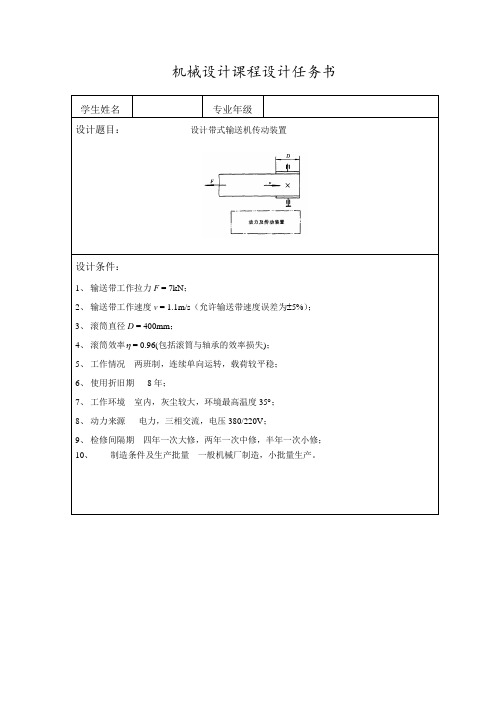
机械设计课程设计任务书学生姓名专业年级设计题目:设计带式输送机传动装置设计条件:1、输送带工作拉力F = 7kN;2、输送带工作速度v = 1.1m/s(允许输送带速度误差为±5%);3、滚筒直径D = 400mm;4、滚筒效率η = 0.96(包括滚筒与轴承的效率损失);5、工作情况两班制,连续单向运转,载荷较平稳;6、使用折旧期8年;7、工作环境室内,灰尘较大,环境最高温度35︒;8、动力来源电力,三相交流,电压380/220V;9、检修间隔期四年一次大修,两年一次中修,半年一次小修;10、制造条件及生产批量一般机械厂制造,小批量生产。
设计工作量:1、减速器装配图1张(A1);2、零件工作图3张;3、设计说明书1份。
指导教师签名:2014年7月02日说明:1.此表由指导教师完成,用计算机打印(A4纸)。
2.请将机械设计课程设计任务书装订在机械设计课程设计(论文)的第一页。
设计内容计算及说明结果1.前言2.传动装置的总体设计2.1比较和选择传动方案这次设计的机构要求连续单向运转,载荷平稳,室内工作环境恶劣(灰尘较大,环境最高温度350C),还要求维修方便,故选用的是展开式二级圆柱齿轮减速器。
在这次课程设计过程中,为了更好地达到培养设计能力的要求,应养成独立思考,严肃认真,精益求精的好习惯。
还要综合考虑多种因素,要采取多种办法进行比较分析。
最重要的是,通过这次的课程设计,要学会机械设计的一半规律,树立正确的设计思想,还要学会用计算机绘图。
这次设计的机构要求连续单向运转,载荷平稳,室内工作环境恶劣(灰尘较大,环境最高温度350C),还要求维修方便,故选用的是展开式二级圆柱齿轮减速器。
本传动机构的特点是:减速器横向尺寸较小,两大齿轮浸油深度可以大致相同。
结构较复杂,轴向尺寸大,中间轴较长、刚度差,中间轴承润滑较困难。
结构如下:设计内容计算及说明结果2.2电动机的选择2.2.1电动机类型2.2.2确定电动机功率2.2.3确定电动机转速2.2.4选定电动机2.3计算总传动比和分配各级传动比参数题号 9输送带工作拉力F/KN 4.2输送带工作速度v(m/s) 1.9滚筒直径D(mm) 450选用Y系列三相异步电动机工作机的效率96.0jw=η=η传动装置中各部分的效率,查机械设计课程设计手册表1-78级精度的一般齿轮传动效率97.0=η齿高速级弹性联轴器传动效率99.0=η联低速级齿式联轴器传动效率99.0l=η滚子轴承传动效率)(99.0一对球=η电动机至工作机之间传动装置的总效率lηηηηηηηη滚子齿滚子齿滚子联=89.099.099.097.099.097.099.099.0=⨯⨯⨯⨯⨯⨯=工作机所需功率4200 1.98.31100010000.96wwFP KWνη⨯===⨯所需电动机功率8.319.340.89wdPP KWη===采用同步转速1500r/min查出电动机型号为Y160L-4,其额定功率为11kW,满载转速1460r/min。
高楼逃生装置设计

Abstract
Firstly,this paper describesthebackgroundand significanceoftallbuildingescapedevice.And someof the existingtall buildingescape devicesareanalyzed and compared,most of the devices are costly, complex organization, the safety factor and low number of shortcomingsare found.The design applied theory of inventive problem solving.To design a negative feedback loop system based ontall buildingescape device.The device hasmanyadvantages such aslow cost, simple operation, high safety factor, purely mechanicalno electrical structure.Finally, the components of the calculated design agency.The graphicsgetin the whole body,after many tests and analysis, determiningwhether children or the elderly can safely descend to the ground from high buildings.the purpose of this designhas achieved.
- 1、下载文档前请自行甄别文档内容的完整性,平台不提供额外的编辑、内容补充、找答案等附加服务。
- 2、"仅部分预览"的文档,不可在线预览部分如存在完整性等问题,可反馈申请退款(可完整预览的文档不适用该条件!)。
- 3、如文档侵犯您的权益,请联系客服反馈,我们会尽快为您处理(人工客服工作时间:9:00-18:30)。
目录1 绪论 (1)1.1 课题的研究背景及意义 (1)1.2 国外在高层建筑消防救援方面的研究现状 (2)2 本课题的研究项目 (3)2.1 简析现有的两种高层救援方案的利弊 (3)2.1.1 基于电磁发射技术的抛射装置 (3)2.1.2 直升飞机在高层建筑消防救生 (4)2.2 本课题提出的设计思路 (7)2.3 本方案的独特之处 (9)2.4 方案具体具体实施方式 (10)3 本项目主要部件设计内容 (15)3.1 减速器的设计 (15)3.1.1 设计任务指标 (15)3.1.2 电动机的选择计算 (15)3.1.3 传动装置的运动及动力参数计算 (16)3.1.4 带轮的设计计算 (18)3.1.5 减速器中高速级圆锥齿轮设计计算 (21)3.1.6 减速器中低速级斜齿轮设计计算 (24)3.1.7 轴的设计计算 (29)3.1.8 滚动轴承的选择及寿命验算 (35)3.1.9 键连接的选择与验算 (36)3.1.10 联轴器的选择 (36)3.2 绳索的选用 (36)3.2.1 白棕绳及合成纤维绳 (37)3.2.2 钢丝绳 (38)3.3 合适的动力伞发动机选用 (44)3.4 动力伞安全飞行条例 (45)结束语 (46)致谢 (47)参考文献 (48).1 课题的研究背景和意义随着科技的进步、土地资源的稀贵,高楼(一般指七层以上高度的建筑物)的发展极为迅速,数量急剧增加,但随之而来的火灾事故数量也不断攀升,更要紧的是随着建筑物高度的增加[1],消防救援工作难度跟着急剧增加,特别是其中的高层和超高层建筑的消防救援更历来是一个世界性难题,直到现在一直没有一个综合性良好的解决方法。
这是因为高楼失火后,高楼内部楼道往往被大火和浓烟封堵,难以进入,消防救援主要靠在高楼外面进行,而目前消防部门通常用于灭火的主要装备如消防水罐车等其灭火喷射高度十分有限,对高楼层的火灾则鞭长莫及,而且还不能直接立即实施救援中的救生项目[2]。
相对有效地救援主要是通过云梯消防车、带有登高平台或举高的消防车等大型车载攀升或攀扶设备将人员及或器材送达所需高度实施消防救援,但这些设备绝大多数最高也只能伸展至53米,相当于约十五层楼的高度,而就是这样的消防装备对我国大多数城市来说也还都不是具备的.因为随着举升高度的增加其设备成本急剧上升,许多城市难以承受[3]。
目前世界上最高的消防云梯车为荷兰生产的110米,但也只能达到约三十几层高的高度,而其价格却极为昂贵,目前我国仅杭州市进口了一台,但由于这类消防车超大的重量及体积,其通过性、机动性、灵活性、高位负重能力、营救效率速度及对地面支承环境的适应性等都较差,特别是其极其高昂的价格,显然在未来很长时期之内,中小城市是无法普及的,更致命的是当楼层高度超过其使用高度时无法使用,只能“望楼兴叹”,而现在城市中二、三十层以上高度的高楼已越来越多[3]。
高层建筑消防救援的能力已经成为衡量和检验一个国家、地区或城市消防现代化水平和战斗力的重要标志,这是现代化都市所面临的一项重要课题。
特别是美国“9.11”事件再次给世界高层建筑消防安全敲响了警钟。
因此,能“更高”、“更强”、“更省”“更普及”地解决高层建筑消防救生与灭火显而易见将具有重大的经济与社会效益。
消防部门急需一种全新的高层建筑消防救生装置,能够基本不受建筑高度限制,较好地解决高层建筑消防救生(也可适当附带灭火)的难题。
而且设备结构还要简单,生产成本低,产品实施简便易行,廉价、快捷,特别易于普及使用[6]。
1.1 国外在高层建筑消防救援方面的研究现状有鉴于高层建筑直接救生灭火设备开发与实施的极端困难性,目前国内外高层建筑救生与灭火设备的最新发展有以下趋势:继续研发更高高度的云梯消防车以及开发性能更好、适合救火的直升机,但目前依然实际困难很大。
性能更好的设备并商品化的目前尚未见到相关报道。
目前多数公司或机构转而集中致力于创新、开发能辅助高层建筑消防救生与灭火的外围相关产品,但一般不能直接进行救生灭火,主要有以下进展趋势:火场机器人。
把带有视频头的机器人送到着火地区,特别是可能有毒气等条件恶劣的地方代替消防人员搜索被困者。
美国一个叫“安娜·肯达”的搜索机器人,像一条大蛇,它有三米长,共有22个节,顶部的摄像头能转动33个角度,全方位观察特定区域内情景。
主要适于火场搜索,能辅助救生,但造价昂贵,不能直接用于高层救生、灭火[7,11]。
超大型超高压灭火喷枪。
基德消防公司是美国联合技术公司旗下的分公司,他们的超大口径高压泵,能够在极短时间内,喷射非常大的灭火水流,或是将灭火泡沫喷至约140米的高空。
但较难射中室内指定地点,更不能直接救生。
未来型灭火机器人。
德国一公司设计了一外形很像是甲壳虫的未来型灭火机器人,配备全球定位系统导航,并携带一到数个水箱,在遥控中心的指挥下,“自行”前往火区灭火,使消防人员远离危险。
可以爬楼,但对于楼层过高而楼内通道受阻的情况却束手无策,难以直接救生[7,14]。
造价昂贵。
遥控搜寻飞机。
这种小飞机上的摄像系统,能够透过浓烟和黑夜及高温烈焰,拍摄到现场情况并将信息传到消防指挥中心。
但不能直接救生和灭火。
2本课题的研究项目通过分析国内外现有的高层救生方案的弊端,提出了一种适于中国现有城市环境的高层救援方案,此方案可以基本不受建筑高度限制,较好地解决高层建筑消防救生(也可适当附带灭火)的难题。
2.1 简析现有的两种高层救援方案的利弊2.1.1 基于电磁发射技术的抛射装置此技术是将灭火装置和救援器材等消防救援装备以较低的速度由高层建筑的窗口发射到内部供给消防队员和被困人员开展灭火救生行动,为实施灭火救援工作提供保障。
抛射器结构原理抛射器基于电磁发射技术,基本结构为电磁炮[8]。
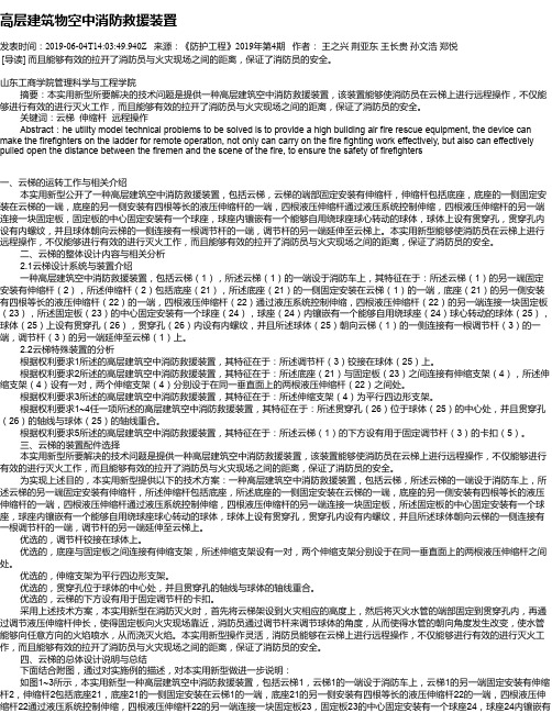
图1为抛射器的结构示意图。
在导轨炮的两条平行导轨之间设置弹射体,弹射体与重接炮的支撑座固定连接;支承座的两侧设置重接炮的线圈,与重接炮线圈垂直的方向上对称设置两块挡板;两块挡板之间的空间用于装载抛射体。
在此结构中,导轨炮水平设置,用于给抛射体一个水平方向上的速度,线圈炮竖直设置,用于给抛射体一个竖直方向上的初速度,在导轨炮和重接炮的配合作用下,抛射体在水平方向上做匀速直线运动,在竖直方向上做竖直上抛运动,抛射体的运动轨迹是一条抛物线,通过控制水平速度和竖直速度,使抛物线的最高点作为进入高层建筑窗口的入射点。
图1 抛射器的结构示意图图中1.导轨炮2.重接炮线3.抛射体1.壳体2.吊环3.支撑轮4.铰支架4.挡板5.支撑座6.弹射体5.绳盘6.绳索此设计虽然成本低,结构简单,可是存在几个很严重的问题:1.实际参加过救援的人员都知道,这类动力发射装置准确性极差,即使建筑物上有门窗等,因挂靠物很高,而且又很小,因此很难命中,楼层越高问题越大,命中率会急剧下降,不知要发射多少次也难以命中,且不谈累计发射成本高低,更要紧的是每次失败都还要收回已发射的绳索长度(接近高楼高度)包括锚勾等一整套装置机构并重新进行安装发射,火场极其宝贵的时间会被大段地浪费,而每一分钟都可能意味着生命的代价。
2.由于射击准确度太低,有可能会打到其它窗户或门内,即时射击命中,但由于对窗户或门里面人员情况不明还可能会发生次生危险,不够安全。
3. 该设计要求作为空中另一支点的挂靠物强度应保证达到500公斤以上(其实安全余量是不够的),以便一人先上去重新挂靠牢实,但遇到较高楼层,需携带的绳索会很长(意味着绳重量更重),而这类携绳抛绳器负重又非常有限,因此绳索只能很细,承载能力自然降低,一人缘该绳爬高救生其安全性令人担忧,以致实际上当楼很高时往往会无法实施所述的一人先行缘绳上去。
就算一人可以先上去,却不能在第一次就立即多人及或重器材一同上去,这也浪费了许多宝贵的救火时间,更要紧的是,失火现场建筑物特别是很高的高楼上被锚定钩住的挂靠物所在距离很远,固定物自身的牢固程度很难看清或很快判定,锚定装置是否已牢靠地抓、挂、勾住固定物还是仅仅挂了固定物的一个边角或其松软不结实之处等也都很难确定,而每座高楼的情况又是千差万别的,在紧急的火场氛围下是很难快速做出无误判断的,而挂靠物的牢靠与否事关待救人员与消防人员的生命安全,如看不清而仅靠现场拍脑袋估计挂靠物的牢度和可靠程度,这对消防救援工作可是一个大忌,要冒很大的风险,用于实战装备还存在很大问题,而作为一项实用技术方案更必须完全可靠和安全才能被消防部门作为一种正常的消防方法接受和使用,发射锚定后先人工试拉拉看强度可否,不行就再重新发射,也正是此意,但人命关天,这试一试可不是简单的拉一拉就能确定的,即使能确证强度不行,这重新收回再发射又可能浪费大量的宝贵营救时间[4,9],这也可以说是这一方法的另一个致命伤了。
4.不少实际的高层建筑物立面墙上或救援点附近立面墙上根本没有明显的凹凸物、窗门、阳台等可附着物,墙面大面积几乎全是“光面”,如玻璃幕墙或类似物等,此法则很难实施或要浪费很多周折和时间来解决,更不用说快速准确定点救援了,这在火场救援中也差不多是一个很大的致命伤了,5.采用压缩空气做动力的抛射体其飞行高度有限,何况还要负重,而且楼越高需绳越长,负重也越大,抛射高度自然越低,因此遇到很高的楼层很可能无法实施该方案,这也是一个大大的问题。
2.1.2 直升飞机在高层建筑消防救生直升机被越来越广泛地应用到消防领域,如森林火灾的扑救、高层建筑火灾的救援。
随着城市中摩天大楼高度的不断增加,利用直升机将消防队员和装备运到发生火灾的高层建筑顶部执行搜索、救援和火灾扑救任务的优势越来越明显,已经引起国际消防界的高度重视。
(1) 直升机在高层建筑消防救援中的应用现状直升机最初被广泛用于森林火灾扑救,20世纪60年代末才开始扩大到城市消防领域。
1966年11月1日,日本东京成立了第一支空中消防队,标志着直升机真正开始应用于城市建筑物消防救灾。
在随后的二十年内,特别是美国的部分大城市在70年代中后期陆续规定高层建筑物顶层需设有供直升机起降的救生平台,为直升机真正广泛地用于高层建筑救援和消防奠定了重要基础[9,11]。
由于直升机具有机动灵活的飞行特性,包括起降限制条件少、空中停留盘旋、任意方向前进后退等。
因此,在消防救灾行动中,较之消防车,直升机具有无可替代的优点。
直升机在高层建筑物火灾的抢救中主要具有5个方面的作用,即救助被困人员、火灾侦查、现场指挥、运载人员和装备以及直接灭火。
2009年5月29日,上海政府飞行队暨上海市公安局警务飞行大队成立,上海市配置消防直升机的事宜也已提上日程,而且已经进入机型筛选阶段。
在为中国城市飞速发展和城市管理手段日新月异感到自豪的同时。
也认识到直升飞机在城市中的运用却有以下几个重要缺陷。