高斯Newsliner90机最佳接纸方式探秘
士林_温控器操作手册

22
9.2 Level2 (PID 層)
8.2.1
參數“顯示/隱藏”條件 .....................................................
23
8.2.2
參數說明 ......................................................................
41
15.2 軟體部分 .................................................................................................
42
16 更改輸出類型 : Relay , SSR , 4~20mA ............................................................ 43
7
2.4 安裝及配線......................................................................................
8
2.5 操作說明..........................................................................................
17
7 操作步驟說明
7.1 開機 ...............................................................................................
18
7.2 設定 SV ..........................................................................................
依玛仕培训修订

4.(屏幕左上角显示OFF时) 断开电源
注意: 关机时不需要手洗喷嘴!
Page 4
开墨线
开墨线(启动喷码机时,墨线会自动开启.)
按键
指示灯
操作面板显示内容
等待约45秒:
注意:开墨线用于喷头清洗后重新快速恢复运行喷印操作!
Page 5
关墨线
关墨线
按键
指示灯
操作面板显示内容
注意:关墨线用于喷头清洗或其他维护操作!
5.按 “ENTER” 键 墨线指示灯由不亮变为 闪亮(等 3分钟),
6.当墨线指示灯稳定 时就可以喷印了 7.把喷头固定在生产线上
注意:如有故障详见维护操作,不要调节喷头任何配件!
Page 3
日常关机
日常关机
2.按 “ON/OFF” 键
1.把喷头放在维护 支架上
3. .按 “ENTER” 键 墨线指示灯灭(等 2分钟),
依玛仕 9020/9030 喷码机培训教程
河南中沃实业有限公司
第一部分:基本操作
1、 日常开关机 2、 开关墨线
3、 清洗喷头
4、 喷头维护操作 5、 信息编辑
Page 2
日常开机
日常开机
3.插通电源,控制面板 指示亮
1.检查油墨以及添加剂 2.把喷头放在维护 支架上
4.按 “ON/OFF” 键 墨线指示灯不亮
Page 18
信息编辑
◆ 信息保存与关闭
51、“退出”,再下 移选择“信息”中 的“存”
52、再次确认信息名 或输入新的信息名
53、如果信息名已经 存在,则会有上图提示
54、确认后保存生 效,信息已经保存
55、按 “退出” 后上 移至关闭信息编辑功能
卷筒纸凹印机不停机交接纸的几种方式
卷筒纸凹印机不停机交接纸的几种方式1.不减速交接纸和减速交接纸根据整个交接纸过程中机器速度是否改变,不停机交接纸有:不减速交接纸和减速交接纸两种型式。
大多数采用不停机交接纸的凹印机,其机器速度保持不变,不发生人为的改变,即采用“不停机——不减速”交接纸方式。
但是,也有一些凹印机,在交接纸时先将机器速度降低到一定范围内,在交接纸完成后再恢复先前的工作速度,即采用“不停机——减速”交接纸方式。
采用后一种方式是为简化系统结构、降低交接纸过程对张力系统的影响、保持套准的稳定性等。
比如特别高速的机器如果进行标准产品的生产,在计算机的控制下,可将机器速度从500米/分降低到250米分左右进行交接操作。
2.搭接交接纸和对接交接纸根据新旧料带之间的连接方式,不停机交接纸有:对接和搭接两种型式。
搭接是指新料带和旧料带的接头有一定长度的叠加,两者之间靠双面胶带粘接。
显然这样接头处的厚度有一定的增加。
它是目前最常见的一种料带连接方式,适合于所有薄膜、薄纸(软包装、装饰、水松纸等)和厚度不大的卡纸等。
对于厚度在一定范围以上(大约250克/平方米)的纸板,由于搭接厚度会影响到印刷副压力,可能使机器产生振动、使压印滚筒损坏,因此是不可取的。
这时应该采用对接方式。
对接实际上又有两种型式式:高速对接和采用储纸器对接。
(1)高速对接纸此种系统的启动机构要求比搭接更强、时间控制更关键、更复杂,但可以达到在高达200米/分甚至更高速度下进行“头——头”对接。
显然,前边沿必须做特殊准备。
可以达到零间隙对接,但通常是大约有2—3毫米的间隙,可胶带连结。
在一些要求厚薄纸都能印刷的凹印机上,通常具有搭接和高速对接两种系统。
这样操作者在印刷薄纸时可使用搭接方式,而在印刷纸板时可使用高速对接方式。
(2)采用储纸器对接纸储纸器中存储了相当长度的纸带。
储纸器在涂布工艺时常用,在印刷纸板的包装凹印机上也经常见到。
它的主要缺点是:总的纸带长度很大,对张力控制的连续性有影响,进而影响到套印。
新月型高速卫生纸机的安装

2 纸机安装
准备工作:根据预埋钢板、预留孔等找出纸机和 Yankee烘缸中心线,并引出这些中心线,在_楼面上 制作永久的这些中心线标记,有利于提高安装精度、 速度和方便维修。同时,g,N具备精度高达0.2mm的 水准仪、1 27ram(5”)的经纬仪、磁吸座等。
厂西贵糖(集团)股份有限公司第三造纸J‘引进2 台新月犁高速卫阜纸机,幅宽2 7 00mm,发计车速 1 500m/min,年产中高档卫生纸5万吨,现“l机、“2 机均已顺利投产。
1 纸机特点
L1 纸机结构特点 湿郜采用不锈钢或包覆不锈钢结构。阶梯扩散型
流浆箱,新月型成形器,网、毯部悬臂梁结构,能实现 快速换网、毯,真空压榨辊。Y a nk e e烘缸直径¥ 4572film,长5839mm,重量65t(单缸)。T、湿部两个高 效汽罩,通过风机、风管把液化气燃烧(独立液化气 站)产生的热风吹到汽罩干燥纸呱,后冉吸回湿热废 气,循环利用热量。两辊压光,纸机载荷集中。
嚣。题移.应塌拉术圜
岛国四
岛固雾盆绣观国营爨
。甘远居[广西贵糖(集团)股份有限公司广西贵港537102]
提要:介绍7新月型卫生纸机的安装经验厦系统配置,尤其是Yankee烘缸的运输与安装。 关键词:新月型卫生纸机;YanKee±#r,缸;安装;特点
T钾弓 吕
甘远居,广西责糖(集 团)股份有限公司第三 造纸厂机械工程师。贞 责年产5万吨(实际年产 约5万吨)生活用纸技改
需定位的部件都标有基准线,零部什加上精度非 常高,能保证准确装配尺寸,易于安装。 1.2纸机基础特点
MEG零速自动接纸机使用手册

自 动 接 纸 ···········································································22
手 动 接 纸 ···········································································22
2.1 机 器 外 形 ·············································································4
2.2 机器主要构成 ·············································································5
达到向印刷机连续不断地输送纸张。从而最大限度地发挥了印刷机的印刷效率。
本接纸机采用独立的气动调节辊建立和维持卷筒纸的张力,使纸张稳定的
进入印刷机。保证了印刷机的印刷质量。
本接纸机采用框架式结构,占地面积小,易于安装,易于操作和维护。
使用本接纸机后,可得到以下三点收效:
1) 由于接纸过程自动完成,因而减少印刷工人的劳动强度。
紧急停止调整 ···········································································24
6.
维 护 保 养 ···········································································25
4.1 升降机限位调整 ·······································································10
FMG90系列电磁流量计操作手册说明书

FMG90 SeriesElectromagnetic Flow Meter- 2 - M-5204/0615Table of contents page 0About this operating manual (4)1Device description (5)1.1Intended use (6)1.2Exclusion of liability (6)2Safety instructions (7)3Construction and function (8)4Installation of FMG90 (8)4.1Installation instructions (9)4.2Assembly (10)5Electrical connection (11)6Commissioning and measuring operation (12)6.1Commissioning (12)6.2Measuring operation (12)7Maintenance and cleaning (12)8Disassembly and disposal (13)9Technical data (14)9.1Characteristics FMG90 (14)9.2Materials table (15)9.3Pressure drop (15)9.4Dimensions (16)Copyright notice:The reproduction, distribution and utilization of this operating manual as well as the communication of its contents to others without express authorization is prohibited. Offenders will be held liable for the payment of damages. All rights reserved in the event of the grant of a patent, utility model or designTechnical changes reserved - 3 -About this operating manual Series FMG90- 4 - M-5204/06150 About this operating manual• The operating manual is aimed at specialists and semi-skilled personnel.• Before each step, read through the relevant advice carefully and keep to the specified order.•Thoroughly read and understand the information in the section "Safety instructions".If you have any problems or questions, please contact your supplier or contact us directly at:One Omega Drive, P.O. Box 4047Stamford, CT 06907-0047 Tel: (203) 359-1660 e-mail:**************Hazard signs and other symbols used:WARNING! / CAUTION! Risk of injury!This sign indicates dangers that cause personal injuries that can lead to health defects or cause considerable damage to property.CAUTION! Electric current!This sign indicates dangers which could arise from handling of electric current.CAUTION! Material damage!This sign indicates actions which could lead to possible damage to material or environmental damage.ADHERE TO OPERATING MANUAL! NOTICE!This symbol indicates important notices, tips or information. NO DOMESTIC WASTE!The device must not be disposed of together with domestic waste.Pay attention to and comply withinformation that is marked with this symbol.Follow the specified instructions and steps.Adhere to the given order.❑Check the specified points or notices.Reference to another section, document orsource. • Item.Series FMG90 Device descriptionTechnical changes reserved - 5 -1 Device descriptionThe FMG90 series from Omega, is a non-contact flow sensor. The measurement is performed using magnetic induction and works without any moving parts.The FMG90 is used for measuring or metering water and aqueous solutions. The compact design and independence from the intake and discharge sections allows the FMG90 to be used under a variety of conditions.Components:① Sensor housing:The sensor housing consists of plastic and has the IP65 degree of protection.② Electrical connection:The electrical connection is made via 4-pin plug M12x1.③ Operation / flow indicator LED.④ Type plate with flow direction (marking)⑤ Process connection:The process connections are available in different sizes.Versions: The FMG90 is available with different inner diameters from 0.118 to 0.98 in..The versions can be configured differently ( FMG90 Data sheet).Scope of delivery and accessories:Before installing the device, check that the delivered items and ordered accessories:Scope of delivery:❒1x FMG90 as ordered.❒ 1x Operating manual. ❒ 1x Packaging.Device descriptionSeries FMG90- 6 - M-5204/0615Accessories:❒ Connection cable with moulded M12x1 couplingsocket.❒ M12x1 coupling socket as component.1.1 Intended useThe magnetic inductive flow sensor FMG90 must only be used for measuring and metering liquids with a minimum conductivity of 20 μS/cm.WARNING! No safety component!The magnetic inductive flow sensor of the series FMG90 are not safety components in accordance with Directive 2006-42-EC (Machine Directive). Never use the FMG90 as a safety component.The operational safety of the device supplied is only guaranteed by intended use. The specified limits (♑ § 9 "Technical data") may under no circumstances be exceeded.Before installing the device, check that the wetted materials of the device are compatible with the media being used (♑ § 9.2 "Materials table").Measuring tube empty (or partially filled). / Conductivity too low.The green LED may blink irregularly if the measuring tube of the FMG90 is empty or partially filled or if the conductivity of the fluid being used is too low. Random pulses will be present at the output, but they do not represent an actual flow.Ensure that the measuring tube of the FMG90 is always completely filled (♑ § 4.1 "Installation instructions").Ensure that the conductivity of the fluid is at least 20 μS/cm.1.2Exclusion of liabilityWe accept no liability for any damage or malfunctions resulting from incorrect installation, inappropriate use of the device or failure to follow the instructions in this operating manual.Series FMG90 Safety instructionsTechnical changes reserved - 7 -2Safety instructionsBefore you install the FMG90, read through this operating manual carefully. If theinstructions contained within it are not followed, in particular the safety guidelines, this could result in danger for people, the environment, and the device and the system it isconnected to.The FMG90 correspond to the state-of-the-art technology. This concerns the accuracy, the operating mode and the safe operation of the device.In order to guarantee that the device operates safely, the operator must act competently andbe conscious of safety issues.Omega provides support for the use of its products either personally or via relevant literature. The customer verifies that our product is fit for purpose based on our technical information. The customer performs customer- and application-specific tests to ensure that the product is suitable for the intended use. With this verification all hazards and risks are transferred to ourcustomers; our warranty is not valid.Qualified personnel:The personnel who are charged for the installation, operation and maintenance of the FMG90 must hold a relevant qualification. This can be based on training or relevanttuition.The personnel must be aware of this operating manual and have access to it at all times.The electrical connection should only be carried out by a fully qualified electrician. General safety instructions:In all work, the existing national regulations for accident prevention and safety in the workplace must be complied with. Any internal regulations of the operator must also be complied with, even if these are not mentioned in this manual. Degree of protection according to EN 60529:Please ensure that the ambient conditions at the site of use does not exceed the requirements for the stated protection rating (§ 9 "Technical data").Only use the FMG90 if it is in perfect condition. Damaged or faulty devices must be checked without delay and, if necessary, replaced.When fitting, connecting and removing the FMG90 use only suitable appropriate tools. Do not remove or obliterate type plates or other markings on the device, as otherwise the warranty is rendered null and void. Special safety instructions:(Further) Warnings that are specifically relevant to individual operating procedures or activities can be found at the beginning of the relevant sections of this operating manual.Construction and function Series FMG90- 8 - M-5204/06153 Construction and functionConstruction:The measuring tube with its earthing sleeves and electrodes passes through the sensor housing and forms the external process connection of the FMG90.A magnetic field for the measurement process is generated inside the sensor housing, which also contains the sensor and signal conditioning circuitry.The two stainless steel electrodes are located in the middle of the measuring tube between the earthing sleeves. The FMG90 does not need any moving parts to make measurements. The inside of the measuring tube is completely open, allowing the fluid to flow unhindered through the measuring tube.Function:The magnetic inductive flow sensor functions according to the induction principle: The measuring tube is located in a magnetic field (B). If an electrically conductive medium (V) flows through the measuring tube and, therefore, at right angles to the magnetic field, a voltage (U) which is proportional to the mean flow velocity will be induced in the medium and subsequently picked up by the two electrodes.4 Installation of FMG90Before installing, check that❒ the wetted materials of the device are suitable for the media being used ( § 9.2"Materials table").❒the equipment is switched off and is in a safe and de-energized state. ❒ the equipment is depressurized and has cooled down.SUITABLE TOOLS:Use only suitable tools of the correct size.Series FMG90 Installation of FMG90Technical changes reserved - 9 -4.1 Installation instructionsCAUTION!Risk of malfunction due to external magnetic fields!Magnetic fields close to the device can cause malfunctions and should be avoided.Ensure that no external magnetic fields are present at the installation site of the FMG90.•The FMG90 can always be installed anywhere along the pipeline. Straight sections of piping are preferable, however.•Installation can occur in horizontal and vertical pipes. The flow sensor is only suitable for application in completely filled pipe systems.•As a matter of principle magnetic inductive flow sensors are widely independent from the flow profile. An inlet section is not absolutely necessary.To reach a most highly accuracy of the measurement, you should use straight inlet and outlet sections according to the inner diameter. The inlet section has to be at least10 x inner diameter; the outlet section 5 x inner diameter in order to achieve the specified accuracy.•The inlet and outlet sections and the gaskets must have the same or a slightly larger inside diameter than the measuring tube in order to achieve the specified accuracy.Installation of FMG90 Series FMG90- 10 - M-5204/0615•If two or more FMG90 devices are used side by side, maintain a separation of at least 1.0 in between adjacent devices.If adjacent devices are too close together, operation of both devices may be impaired due to mutual interference.4.2 AssemblyThe FMG90 is installed directly into the pipeline. The compact design and light weight of the unit make wall-mounting unnecessary.IMPORTANT NOTICES:• Observe the flow direction indicated on the type plate.• Observe the mounting dimensions (♑ § 9.4 "Dimensions").Select an appropriate location for installation (♑ § 4.1"Installation instructions").To ensure the best possible measuring accuracy, a vertical installation position with increasing flow is preferable (no collecting of dirt deposits).Wrap the FMG90 connections with 1 to 2 wraps of threadtape (e.g. Teflon ® tape). Wrap tape in a clockwise direction, viewed form the end, leaving the first two threads uncovered. Make sure the tape does not intrude into the flow path.Attach the FMG90 with arrow pointed in the direction of flow. The fittings should be screwed into FMG90 hand tight.CAUTION! Material damage!Do not use excessive force. The FMG90 can be damaged.While tightening, counter the FMG90 only by hand! If you use an open-end or a pipe wrench, the FMG90can be damaged.To tighten the FMG90, use an open-end or a pipewrench for the fittings and only the hand for the FMG90. Tighten the FMG90 an additional ¾ to 1 turn.Series FMG90 Electrical connectionTechnical changes reserved - 11 -5 Electrical connectionThe electrical connection of the FMG90 is via the 4-pin plug M12x1 at the top.The corresponding connection cables with moulded coupling socket are available in various lengths included in the range of Omega accessories.CAUTION! Electric current!The electrical connection should only be carried out by a fully qualified electrician. De-energize the electrical system before connecting the FMG90.Connection and wiring:Screw the coupling socket of the connection cable to the plug of the FMG90. Tighten the knurled nut of the coupling socket with a maximum torque of 1 Nm. Connect the connection cables according to the following wiring diagrams. Pin assignment:Pin 1: +U B Pin 3: GNDPin 2 / 4: Frequency output NPN/PNPPin configuration with NPN frequency output:PNP frequency output:Pull-up- / pull-down-resistors R .We recommend using resistors of ~1 kΩ (12V) respectively ~2,2 k Ω (24V) and 0.25 W for the pull-up / pull-down wiring.Please note that the maximum signal current of 25 mA will not be exceeded.Commissioning and measuring operation Series FMG90- 12 - M-5204/06156 Commissioning and measuring operationBefore switching on the FMG90 for the first time, please follow the instructions in the following section.6.1 CommissioningCheck that❒ the FMG90 has been installed correctly and that all screw connections are sealed. ❒ the electrical wiring has been connected properly. ❒ the measuring system is vented by flushing.Switch on the supply voltage.The red LED lights permanently. The FMG90 is ready for use and goes into measuring operation.6.2 Measuring operationThe red LED is constantly lit to indicate that the FMG90 is operational.The green LED blinks according to the frequency of the output signal.This blinking is not perceptible to the human eye at frequencies above 30 to 40 Hz,so the green LED appears to be constantly lit. Frequency output:The frequency output provides a flow-proportional PNP/NPN square wave signal.7 Maintenance and cleaningMaintenance:The FMG90 is maintenance-free and cannot be repaired by the user. In case of a defect, thedevice must be replaced or sent back the manufacturer for repair.CAUTION! Material damage!When opening the device, critical parts or components can be damage. Never open the device and perform any repair yourself.Cleaning:Clean the FMG90 with a dry or slightly damp lint-free cloth. Do not use sharp objects or aggressive agents for cleaning.Series FMG90 Disassembly and disposalTechnical changes reserved - 13 -8 Disassembly and disposalCAUTION! Risk of injury!Never remove the device from a plant in operation.Make sure that the plant is shut down professionally.Before disassembly:Prior to disassembly, ensure that❒ the equipment is switched off and is in a safe and de-energized state. ❒ the equipment is depressurized and has cooled down. ❒Disassembly:Remove the electrical connectors.Remove the FMG90 using suitable tools. ❒ Disposal:NO HOUSEHOLD WASTE!The FMG90 consists of various different materials. He must not be disposed of with household waste.Take the FMG90 to your local recycling plant orsend the FMG90 back to your supplier or toOmega.Technical data Series FMG90- 14 - M-5204/06159 Technical dataThe technical data of customized versions may differ from the data in these instructions. Please observe the information specified on the type plate.9.1 Characteristics FMG90** other pulse rate / resolution on request.optional: Output signal with lower frequency, designed specifically for connection to digital PLC inputs.Series FMG90 Technical dataTechnical changes reserved - 15 -9.2 Materials table9.3 Pressure dropTechnical data Series FMG90- 16 -M-5204/06159.4 DimensionsFMG 91 … FMG 99:FMG 96:Series FMG90 For your notes For your notesTechnical changes reserved - 17 -For your notes Series FMG90 For your notes- 18 - M-5204/0615Series FMG90Technical changes reserved - 19 -Series FMG90M-5204/0615 - 20 - M-5204/0615。
POSTEK打印机用户手册

重要提示
热敏式打印头因为其结构关系,容易受损。由于维护和使用不 当造成的打印头损坏,不在保修范围之内。请注意以下事项,以避 免在正常使用寿命期内损坏打印头: 1. 不能用硬物刮触打印头。 2. 为了避免打印头被腐蚀,请不要用手触摸打印头表面。 3. 为了避免打印头被腐蚀,请不要使用带有钠(Na)离子、钾 (K)离子、氯(Cl)离子的热敏纸。 4. 为了避免打印头被腐蚀, 请不要使打印头接触任何液体或潮 湿的物体。 5. 为了避免打印头被腐蚀,只能用无水乙醇擦拭打印头表面。 6. 请不要使用劣质耗材: (1)某些劣质的标签上带有纸屑、沙尘颗粒以及胶水等污 物,因为打印机工作时胶辊将耗材压紧在打印头上, 所以这些污物在打印过程中极易划伤打印头。 所以购买耗材前请务必确认耗材品质,以免因耗材品质造 成打印头损坏。劣质耗材造成的打印头损坏不在保修范围 内。
版权
深圳市博思得科技发展有限公司保留一切版权。 POSTEK iQ 条码标签打印机用户手册。 二○一五年一月第一版。
免除责任声明
本手册在其出版时,确切地阐述了 POSTEK iQ 条码标签打印机的规 格和使用说明。但是其后生产的打印机的规格以及配置可能会在没 有任何通告的情况下改变。该产品的制造商和经销商对于由本手册 和打印机之间存在的差异甚至错误所造成的直接或间接的损失不承 担任何责任。 尽管本手册对可能发生的问题进行了尽可能详尽的描述,但是不保 证实际使用该打印机的过程中仍有未预见的情况发生。对于使用该 打印机中发生的诸如打印机不工作、打印的内容缺损或不清晰等问 题,该产品的制造商和经销商只负责排除该打印机的故障(依照保 修卡上的保修条款) ,而对于其它任何直接或间接的损失包括商业利 益损失、业务中断损失、商业信息丢失或其它财务损失等不承担责 任。
凯撒电子 PLA 90 耳机霍尔辅助系统用户手册说明书

PLA 90Counter LoopMAN 173DWe would like to congratulate you on purchasing your portable induction loop system PLA 90. Y ou have chosen a modern, reliable device. Please read these operating instructions carefully. This describes how to set up the system correctly and explains all the system features. Standard componentsPlease check if all following components are included:- Portable induction loop system PLA 90 with integrated battery,- Power supply unit- 3 color signal strips- 2 T-coil labels- 4 rubber feet- Operating instructions- Warranty cardIf any parts are missing, please contact your dealer immediately.How it worksThe PLA 90 uses its built-in microphone or an external microphone to pick up sounds and emits them via the integrated induction loop. The signals emitted in this way can be received by a hearing aid that is set to the “T” or “MT” position.Setting up the PLA 90The induction loop system is already completely installed and set up in the housing. All you have to do is to place the PLA 90 at the desired position between you and the person you are talking to and connect the power supply unit. Please note that the microphone on the back of the device should be facing the person speaking.Switching the device onT o switch the induction loop system on, press the “Power on“ button on the rear side of the device. Once the device is switched on, the “Power on” light on the rear of the device will light up green, and the “Power on” light on the front will light up blue.Picking up/ emitting signalsIf sounds are picked up by the microphone on the back of the device or via an external microphone and emitted by the device as magnetic signals, the status light “loop signal” will flash orange.Controls and IndicatorsColor signal stripFront Viewjack microphone input jack Built-in microphone Microphone adjustment Volume control Microphone selection switch (internal/external)Theft protection via Kensington™lockRear ViewAdditional microphone input(3.5 mm plug)An external microphone can be connected to the additional microphone input.Microphone selection switchWith the microphone selection switch you can choose the microphone which should record the sounds.Switch position:Up: internal microphoneDown: external microphoneSetting the sensitivity of the microphone inputWith the control dial on the backside of the device you can adjust the sensitivity of the microphone input. This is useful if you want to connect a low-output microphone to the PLA 90.Headphone jack (3.5 mm plug)Y ou can connect the following products to the Headphone jack:- Under-the-chin receiver- Unobtrusive earphones- Lightweight headset- Audio-Cable monaural- Audio-Cable binaural- Induction Link monaural- Induction Link binauralVolume controlThe volume control adjusts the volume of the headphone jack. Automatic switch offThe PLA 90 will switch off automatically after 2 minutes if no signal is received, from either the internal or external microphone.Charging control lightLED flashes red = Battery is in the process of being rechargedLED off = Battery is fully rechargedPermanent installation of the PLA 90The PLA 90 can be screw-fastened through the lateral holes to a tabletop or other surfaces. The holes are located under the side covers. Remove the covers as shown in the picture below.Retaining clipSide cover Holes for screw fasteningSwitching the device offT o switch the induction loop system off, press the “Power off” button on the rear side of the device. The “Power on” control light goes off.Power supply for the PLA 90The PLA 90 can be operated using the built-in rechargeable battery or the power supply unit. If the battery is fully charged, the device can be used for up to 6 hours.A depleted battery has to be recharged for approximately 3 hours until it reaches full capacity again. Y ou can also use thePLA 90 while it is being charged, but please note that this will lengthen the time required to fully recharge the battery. The device can remain connected to the power supply for as long as desiredWall mounting1. Screw in two screws (not included)14.1 cm apart at the place you would like to mount the PLA 90 on the wall (see figure).2. Now set the PLA 90 on the screws and slide it down slightly to secure it in place.5.55 inChanging the color signal stripY ou can change the color signal strip of the PLA 90, as shown below.Maintenance and careThe PLA 90 does not require any maintenance. If the unit becomes dirty, simply wipe it clean with a soft, damp cloth. Never use spirits, thinners or other organic solvents. Do not set up the unit where it will be exposedto full sunlight for long periods. In addition it must be protected against excessive heat, moisture and severe mechanical shock. Note: This product is not protected against splash water. Do not place any containers filled with water, such as flower vases, or anything with an open flame, such as a lit candle, on or near the product.SpecificationsDimensions:7-7/8" H x 7-1/4" W x 2-15/16" D(200 x 185 x 70 mm)Weight: 1.4 lb (635 g) (with battery installed)Power supply:Input: 100-240 VAC, 50-60 HzOutput: 16 VDCRechargeable battery:12 V NiMH, user-replaceable.Operating time per charge:Up to 6 hoursBattery charging time:Approximately 3 hoursOutput power:10 WMicrophone Sensitivity:Up to 60 dB ±3 dBCE Certification (EU directives):2002/95/EG RoHS 2002/96/EG WEEE 2004/108/EG EMC 2006/95/EG Low voltageCompliance with the directives listed above is confirmed by the CE seal on the device. Specifications subject to change without notice.WarrantyThe PLA 90 is a very reliable product. Should a malfunction occur despite the unit having been set up and operated correctly, please contact your dealer.The warranty covers the repair of the product and returning it to you free of charge during the warranty period. It is essential that you send in the product in its original packaging, so do not throw the packaging away. The warranty does not apply to damage caused by incorrect handling or attempts to repair the unit by people not authorized to do so (destruction of the seal on the unit). Repairs under warranty are only carried out providing the enclosed warranty card is filled out and returned to dealer; also a copy of the sales slip is required.Unit disposalDisposal of used electric and electronic units (applicable in thecountries of the European Union and other European countrieswith a separate collection system). The symbol on the productor the packaging indicates that this product is not to be handledas ordinary household waste but has to be returned to a collecting point for the recycling of electric and electronic units. Y ou protect health and environment by the correct disposal of this product. Material recycling helps to reduce the consumption of raw material. Y ou will receive further information on the recycling of this product from your local community, your communal disposal company or your local dealer.Rechargeable battery disposalThe rechargeable battery that comes with the device can berecycled.Please dispose of this rechargeable battery in receptaclesdesigned for that purpose or return it to a retail outlet. Disposeonly of those batteries that have been completely discharged toensure environmental protection.*******************/ 800-843-3544 / INTL: +1-952-943-2252©2019 Williams AV • All Rights Reserved MAN 173D。
关于传真机的使用
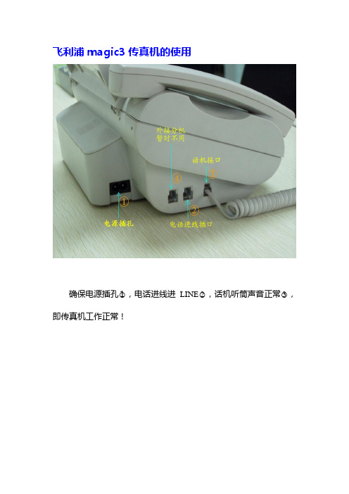
飞利浦magic3传真机的使用
确保电源插孔○1,电话进线进LINE○2,话机听筒声音正常○3,即传真机工作正常!
接收传真
对方电话呼入,拿起话机,等待对方给传真信号,听到嗞嗞的声音后,按下传真机START(开始)键,然后挂上电话。
传真会自动进行,无需其他操作!
如液晶屏幕的右边红灯亮○4,则出现错误,可按STOP键停止后让对方再发一次。
接传真时应确保○2后托盘内有A4的纸张。
发送传真
1.将即将发送的文件发送面,面向自己插入,传真机会自动吸入校正。
(可几张同发)
2.拨通对方电话,告知对方即将发传真。
对方准备完毕后,按下传真机START(开始)键,听到嗞嗞的声音后挂上电话。
传真会自动进行,无需其他操作!
3.发送完毕后,必须再次给对方去电,以确保传真是否收到并清
晰。
直到对方认可为止!
更换色带
飞利浦magic3传真机使用的色带,如色带用完,可到仪器架处的仪器柜下柜处找到新色带。
从图2的○5处向上打开传真,按下图位置刚换即可!。
900 微米光纤连接到 SC 连接器的连接指南说明书

Application Guide #: AG005Revision Date: 012518Splicing 900 Micron Fiber to SCSplice-On-ConnectorSplicers applicable to: KF4A All-in-oneFiber types applicable to: SM, MMEquipment needed:Scissors, Sharpie, Metric Ruler, Soft Bristle Brush, Stiff Bristle Brush, Lint-free Wipe,Cleaning Fluid, Tweezers, Small Phillips Screwdriver, Small SwabsMachine Preparation:1.Ensure that the machine and material to be spliced has had a chance to acclimate to thesurroundings.2.Clean the cameras. Using the swabs and cleaning fluid, wipe the camera lenses asneed be. Use the small Phillips screwdriver to remove the electrodes for better access.Replace the electrodes prior to operation.3.Turn the machine on.4.Select the proper settings on the machine for fiber type, stripper mode, and heater mode(corresponding to splice sleeve). For a splice on connector, the setting typically uses a prefix of “S09” or such.a.These settings may need to be adjusted based on environmental conditions.5.Run an arc calibration cycle (to ensure the machine is set to the environmentalconditions present). If the machine is moved to a new location with differentenvironmental characteristics (i.e. from inside to outside etc), the arc calibration must be run again.6.Examine the machine for general cleanliness. Inspect stripper, heater, cleaver andsplicing areas. If necessary, use soft bristle brush to brush away jacket remnants orsmall pieces of glass from the stripper, heater and cleaver sections. Use stiff bristlebrush to clean v-groove area. Take care not to brush material into v-groove area, intocleaving blade area, or into camera area.Connector Preparation:1. Insert SC assembly into FU-SF holder.2.Ensure that assembly is pushed as far forward within housing as possible to seatproperly, then close magnetic doors.Connector Stripping:1.Open both doors of stripper. If necessary, usesoft bristle brush to brush all stripper surfacesand ensure no jacket or acrylate remnantsremain that could interfere with stripper operation.2.Insert holder loaded with SC Connector. Ensure that the protruding jacketed 900 micronfiber accurately lines up with the channel. Lightly run finger along jacketed fiber toensure it lies within the stripping channel.3.Close the doors of the stripper.4.Check that the machine is set to “900 Micron” for stripper actuation.5.If the stripper actuation button has been pushed previously, the stripper will activateautomatically. If it does not, check the panel of the machine; open the right hand door of the stripper, press the stripper actuation button, and close the right hand door.6.After the automatic stripper operation, open the left door of the stripper. Remove theholder from stripper and examine the fiber.ing a lint free wipe and cleaning fluid, carefully wipe the exposed fiber to remove anyremnants of coating.8.Examine the fiber. If the fiber appears broken or jagged, it may be necessary to beginagain.Connector Cleaving:1.Open door over the cleaving blade and the door over the disposal bin. If necessary, usetweezers to pick up glass remnants and place in bin. Try to avoid sweeping glassremnants into the cleavermachinery to preventinterference; if needed, usea swab and cleaning fluidto draw out material fromcleaver assembly.2.Insert connector holder intocleaver, aligning holder intoguide channel.3.Lightly flip disposal bindoor shut.a.DO NOT force doorshut. Door shouldappear to be slightlyraised in anintermediate position. Door will actuate shut during cleaving operation as part ofthe disposal process. Forcing the door shut at this point WILL DAMAGE thedoor.4.Actuate the cleaver.a.This may be done by closing the door only (on models) or pressing the cleaveractuation button (on other models).5.Open the cleaver blade door.a.The rotating cleaver blade will retract back to a home position. This is a precisionblade and DOES NOT touch the fiber again as it retracts.6.Remove holder from cleaver position and place into splicer. Visually examine to ensurefiber falls into v-groove area properly. If necessary, remove holder and re-seat ontoguide pins. Make sure that the dust cap does not protrude upward and interfere with the wind cover. It may be necessary to remove the dust cap, rotate until the dust cap handle does not interfere, and replace.Fiber Preparation:1.For loose 900 micron fiber,insert fiber through loose SCconnector components.First, slide rear bootassembly on, followed bysplice sleeve.ing a ruler, measure backapproximately 29 mm fromend of fiber. Use Sharpie toapply mark.ing HS-900 holder, openall magnetic doors. Lay fiberwithin channel and holdusing thumb. Align 29mm mark with edge of holder. Close both doors ensuring the fiber is not pinched.Fiber Stripping:1.Open both doors of stripper. If necessary, use soft bristle brush to brush all strippersurfaces and ensure no jacket or acrylate remnants remain that could interfere withstripper operation.2.Insert holder into stripper, aligning holder within the guide channel. Lightly run fingeralong jacketed fiber to ensure it falls within stripper channel.3.Close the doors of the stripper.4.Check that the machine is set to “900 Micron” for stripper actuation.5.If the stripper actuation button has been pushed previously, the stripper will activateautomatically. If it does not, check the panel of the machine; open the right hand door of the stripper, press the stripper actuation button, and close the right hand door.6.After the automatic stripper operation, open the left door of the stripper. Remove theholder from stripper and examine the fiber.ing a lint free wipe and cleaning fluid, carefully wipe the exposed fiber to remove anyremnants of coating.8.If fiber has shifted in the holder (i.e. mark is not aligned with edge of holder), open theholder and realign mark to be flush with edge of holder.9.Examine the fibers. If fiber appears broken or jagged, it may be necessary to beginagain.Fiber Cleaving and Holding:1.Open door over the cleaving blade and the door over the disposal bin. If necessary, usetweezers to pick up glass remnants and place in bin. Try to avoid sweeping glassremnants into the cleaver machinery to prevent interference; if needed, use a swab and cleaning fluid to draw out material from cleaver assembly.2.Insert connector holder into cleaver, aligning holder into the guide channel.3.Lightly flip disposal bin door shut.a.DO NOT force doorshut. Door shouldappear to be slightlyraised in anintermediate position.Door will actuate shutduring cleavingoperation as part ofthe disposal process.Forcing the door shutat this point WILLDAMAGE the door.4.Actuate the cleaver.a.This may be done byclosing the door only(on models) orpressing the cleaver actuation button (on other models).5.Open the cleaver blade door.a.The rotating cleaver blade will retract back to a home position. This is a precisionblade and DOES NOT touch the fiber again as it retracts.6.Remove holder from cleaver position and place into splicer. Visually examine to ensurefiber falls into v-groove area properly. If necessary, remove holder and re-seat ontoguide pins.Arc Fusion Splicing:1. After ensuring that bothholders are in place, closethe door of the splicer.2.Splicer will align the fibersand display a visualrepresentation.a.If the Pause 2setting is activated,the machine willpause for viewing ofthe spliceparameters. Press the Splice Continue button to proceed to splicing.b.If the Pause 2 setting is not activated, the machine will automatically splice whenthe door is shut.3.Upon successful splicing, the screen will display results and estimated loss value. Up to4 additional splice arcs may be performed4.If satisfied with splicing, open the door of the splicer.a.Splicer will automatically perform a tensile proof test on the fiber to ensure splicequality. DO NOT interrupt this test as it is important in verifying a correct splice.5.Slide the splice sleeve close tothe holder.6.Attach the splice support clamp tothe fiber and to the dust cap.Open the magnetic doors of thesplice holders. Use the clamp tocarefully lift the spliced assemblyfrom the splicer.a.Note: DO NOT force thesplicer door shut at thistime. If the magneticholder doors are open, they will interfere with the splicer door. If necessary toshut, ensure splice holders and removed and then shut the splicer door.7.Slide splice sleeve over the exposed splice, taking care to slide the sleeve up to the endof the SC barrel.8.Open heater door.9.Place sleeve within heater area, aligning right edge of sleeve with right edge of heaterarea.a.Due to environmental conditions, it may be necessary to add heat, time, or bothto adequately heat-shrink sleeves.e of a shorter sleeve (example, 25mm) with heater set on longer setting(example, 60 mm) may cause excessive heating of jacket material.10.Close Heater Door.a.Heater may be set to auto-activate upon closing of door.b.If heater does not auto-activate, press the Heater activation button.11.Remove assembly from heater area and allow to cool. Remove splice support clamp.12.Slide SC components up fiber until reaching the spliced connector. Next, slide the rearboot up until snapped on the the back portion of the ferrule assembly. Slide the front shell over the dust cap.While ensuring that thered dot is up, snap thehousing onto theconnector. The red dotshould be aligned with thehousing key.Application Guide #: AG008Revision Date: 012518Splicing 3mm Fiber to SCSplice-On-ConnectorSplicers applicable to: KF4A All-in-oneFiber types applicable to: SM, MMEquipment needed:Scissors, Sharpie, Metric Ruler, Soft Bristle Brush, Stiff Bristle Brush, Lint-free Wipe,Cleaning Fluid, Tweezers, Small Phillips Screwdriver, Small Swabs, Jacket stripperMachine Preparation:1.Ensure that the machine and material to be spliced has had a chance to acclimate to thesurroundings.2.Clean the cameras. Using the swabs and cleaning fluid, wipe the camera lenses asneed be. Use the small Phillips screwdriver to remove the electrodes for better access.Replace the electrodes prior to operation.3.Turn the machine on.4.Select the proper settings on the machine for fiber type, stripper mode, and heater mode(corresponding to splice sleeve).a.These settings may need to be adjusted based on environmental conditions.b.Settings used for this instruction sheet are as follows (KF4A shown):5.Run an arc calibration cycle (to ensure the machine is set to the environmentalconditions present). If the machine is moved to a new location with differentenvironmental characteristics (i.e. from inside to outside etc), the arc calibration must be run again.6.Examine the machine for general cleanliness. Inspect stripper, heater, cleaver andsplicing areas. If necessary, use soft bristle brush to brush away jacket remnants orsmall pieces of glass from the stripper, heater and cleaver sections. Use stiff bristlebrush to clean v-groove area. Take care not to brush material into v-groove area, intocleaving blade area, or into camera area.Connector Preparation:1. Insert SC assembly into FU-SF holder.2.Ensure that assembly is pushed as far forward within housing as possible to seatproperly, then close magnetic doors.Connector Stripping:1.Open both doors of stripper. If necessary, usesoft bristle brush to brush all stripper surfacesand ensure no jacket or acrylate remnantsremain that could interfere with stripperoperation.2.Insert holder loaded with SC Connector.Ensure that the protruding jacketed 900 micron fiber accurately lines up with thechannel. Lightly run finger along jacketed fiber to ensure it lies within the strippingchannel.3.Close the doors of the stripper.4.Check that the machine is set to “900 Micron” for stripper actuation.5.If the stripper actuation button has been pushed previously, the stripper will activateautomatically. If it does not, check the panel of the machine; open the right hand door of the stripper, press the stripper actuation button, and close the right hand door.6.After the automatic stripper operation, open the left door of the stripper. Remove theholder from stripper and examine the fiber.ing a lint free wipe and cleaning fluid, carefully wipe the exposed fiber to remove anyremnants of coating.8.Examine the fiber. If the fiber appears broken or jagged, it may be necessary to beginagain.Connector Cleaving:1.Open door over the cleaving blade and the door over the disposal bin. If necessary, usetweezers to pick up glass remnants and place in bin. Try to avoid sweeping glassremnants into the cleavermachinery to prevent interference;if needed, use a swab and cleaningfluid to draw out material fromcleaver assembly.2.Insert connector holder intocleaver, aligning holder into guidechannel.3.Lightly flip disposal bin door shut.a.DO NOT force door shut.Door should appear to beslightly raised in anintermediate position. Door will actuate shut during cleaving operation as part ofthe disposal process. Forcing the door shut at this point WILL DAMAGE thedoor.4.Actuate the cleaver.a.This may be done by closing the door only (on models) or pressing the cleaveractuation button (on other models).5.Open the cleaver blade door.a.The rotating cleaver blade will retract back to a home position. This is a precisionblade and DOES NOT touch the fiber again as it retracts.6.Remove holder from cleaver position and place into splicer. Visually examine to ensurefiber falls into v-groove area properly. If necessary, remove holder and re-seat ontoguide pins. Make sure that the dust cap does not protrude upward and interfere with the wind cover. It may be necessary to remove the dust cap, rotate until the dust cap handle does not interfere, and replace.Fiber Preparation:1.For 3mm cable, insert fiber through loose SC connector components. First, slide screwcap on, followed by rear boot assembly, and splice sleeve.ing a ruler, measure back approximately 30 mm from end of fiber cable. Use Sharpieto apply mark.ing a hand stripper, remove the outer 3mm jacket from the mark outward.ing a holder for 3mm cable, open all magnetic doors. Lay fiber within channel andhold using thumb. Push cable until 3mm jacket seats against front edge of channel. Pull the Kevlar through the top of the holder next to the hinge (the holder is machined out to have room for the Kevlar to seat).5.Close both doors ensuring the fiber is not pinched. Cut the Kevlar tail approximately inhalf (leaving a tail of approximately 15 mm). Trim the protruding 900 micron - jacketed fiber to 29 mm.Fiber Stripping:1.Open both doors of stripper. If necessary, use soft bristle brush to brush all strippersurfaces and ensure no jacket or acrylate remnants remain that could interfere withstripper operation.2.Insert holder into stripper, aligning holder within the guide channel. Lightly run fingeralong jacketed fiber to ensure it falls within stripper channel.3.Close the doors of the stripper.4.Check that the machine is set to “900 Micron” for stripper actuation.5.If the stripper actuation button has been pushed previously, the stripper will activateautomatically. If it does not, check the panel of the machine; open the right hand door of the stripper, press the stripper actuation button, and close the right hand door.6.After the automatic stripper operation, open the left door of the stripper. Remove theholder from stripper and examine the fiber.ing a lint free wipe and cleaning fluid, carefully wipe the exposed fiber to remove anyremnants of coating.8.If fiber has shifted in the holder (i.e. mark is not aligned with edge of holder), open theholder and realign mark to be flush with edge of holder.9.Examine the fibers. If fiber appears broken or jagged, it may be necessary to beginagain.Fiber Cleaving and Holding:1.Open door over the cleaving bladeand the door over the disposal bin.If necessary, use tweezers to pickup glass remnants and place inbin. Try to avoid sweeping glassremnants into the cleavermachinery to prevent interference;if needed, use a swab andcleaning fluid to draw out materialfrom cleaver assembly.2.Insert connector holder intocleaver, aligning holder into theguide channel. Ensure that Kevlar tail is pulled to the side and does not fall within thecleave area.3.Lightly flip disposal bin door shut.a.DO NOT force door shut. Door should appear to be slightly raised in anintermediate position. Door will actuate shut during cleaving operation as part ofthe disposal process. Forcing the door shut at this point WILL DAMAGE thedoor.4.Actuate the cleaver.a.This may be done by closing the door only (on models) or pressing the cleaveractuation button (on other models).5.Open the cleaver blade door.a.The rotating cleaver blade will retract back to a home position. This is a precisionblade and DOES NOT touch the fiber again as it retracts.6.Remove holder from cleaver position and place into splicer. Visually examine to ensurefiber falls into v-groove area properly. If necessary, remove holder and re-seat ontoguide pins.Arc Fusion Splicing:1. After ensuring that bothholders are in place, closethe door of the splicer.2.Splicer will align the fibersand display a visualrepresentation.a.If the Pause 2setting is activated,the machine willpause for viewing ofthe spliceparameters. Pressthe Splice Continuebutton to proceed to splicing.b.If the Pause 2 setting is not activated, the machine will automatically splice whenthe door is shut.3.Upon successful splicing, the screen will display results and estimated loss value. Up to4 additional splice arcs may be performed4.If satisfied with splicing, open the door of the splicer.a.Splicer will automatically perform a tensile proof test on the fiber to ensure splicequality. DO NOT interrupt this test as it is important in verifying a correct splice.5.Slide the splice sleeve close to the holder.6.Open the magnetic doors of the splice holders. Carefully lift the spliced assembly fromthe splicer.a.Note: DO NOT force the splicer door shut at this time. If the magnetic holderdoors are open, they will interfere with the splicer door. If necessary to shut,ensure splice holders and removedand then shut the splicer door.7.Slide splice sleeve over the exposed splice,taking care to slide the sleeve up to the endof the SC barrel. Ensure that the Kevlar isunder the splice sleeve.8.Open heater door.9.Place sleeve within heater area, aligningright edge of sleeve with right edge of heaterarea.a.Due to environmental conditions, itmay be necessary to add heat, time,or both to adequately heat-shrink sleeves.e of a shorter sleeve (example, 25mm) with heater set on longer setting(example, 60 mm) may cause excessive heating of jacket material.10.Close Heater Door.a.Heater may be set to auto-activate upon closing of door.b.If heater does not auto-activate, press the Heater activation button.11.Remove assembly from heater area and allow to cool.12.Slide SC components up fiber until reaching the spliced connector. Next, slide the rearboot up until snapped on the the back portion of the ferrule assembly. Tighten thethreaded cap over nose of the rear housing. Slide the front shell over the dust cap.While ensuring that the red dot is up, snap the housing onto the connector. The red dot should be aligned with the housing key.。
90°移相 hilbert 算法

90°移相 hilbert 算法
Hilbert算法是一种用于将1D空间映射到2D空间的算法,其中90度相移是算法中的一个操作。
具体实现步骤如下:
1. 初始化一个空矩阵,大小为2的n次方乘2的n次方,其中n为经过Hilbert曲线映射的维度。
2. 对于每个小方块,分为四个象限,按照Hilbert曲线的顺序依次将其坐标映射到矩阵中。
3. 对于每个小方块,根据当前的坐标顺序确定其在Hilbert曲线中的方向,并进行90度的相移。
4. 重复步骤2和步骤3,直到所有小方块都被映射到矩阵中。
通过以上步骤,可以实现将1D空间映射到2D空间,并进行90度的相移操作。
线材对折贴标机操作规程

线材对折贴标机操作规程线材对折贴标机是一种用于对线材进行对折和贴标的设备,该设备具有自动化程度高、效率高等优点,能够大幅提高线材对折和贴标的效率和质量。
为了更好地使用线材对折贴标机,下面是一份操作规程,详细介绍了使用线材对折贴标机的步骤和注意事项。
一、准备工作1. 检查线材对折贴标机的外观是否完好,有无损坏或松动部件。
2. 确保线材对折贴标机的电源已经正确接入,并检查电源线是否有损坏。
3. 查看对折贴标机的标签料和标签纸是否充足,如不足应及时准备。
二、打开对折贴标机1. 打开对折贴标机的电源开关,待设备正常启动后,进入待机状态。
2. 通过调整对折贴标机上的调节装置,将设备的工作台调整到适合操作的高度。
三、设定对折参数1. 根据线材的尺寸和要求,设定对折参数。
通常包括对折规格(如对半对折、三等分对折等)、对折长度和对折角度等。
2. 在对折贴标机的控制面板上,通过按下相应的按钮或旋转调节按钮,完成对折参数的设定。
3. 在设定好对折参数后,进行对折测试,检查对折效果是否符合要求。
如不符合要求,可根据实际情况进行调整,直至满足要求为止。
四、贴标操作1. 将线材放置在对折贴标机的工作台上,并确保线材平整,并且没有被其他物品阻挡。
2. 打开对折贴标机的贴标功能,将标签纸放入对折贴标机的贴标装置中。
3. 按下启动按钮,开始对线材进行对折贴标操作。
4. 当对折贴标操作完成后,及时将已对折贴标的线材从工作台上取下,并将其置放在指定的位置。
五、保养和维护1. 操作完毕后,及时关闭对折贴标机的电源开关,避免长时间待机。
2. 对对折贴标机进行定期的保养和维护,如清洁工作台、清理灰尘等。
3. 定期检查对折贴标机的各个部件,如有损坏或松动的部件,应及时更换或修复。
4. 注意避免对折贴标机受到过高的温度、湿度或震动等外界环境的影响。
六、安全注意事项1. 在操作对折贴标机时,必须佩戴好防护手套和工作服,避免发生意外伤害。
2. 不得随意触碰对折贴标机的运转部件和电源线等,以免发生意外。
高斯(中国)为包装印刷企业提供:一站式“智能智造”的解决方案

高斯(中国)为包装印刷企业提供:一站式“智能智造”的解决方案顾莹一【摘要】日前,上海界龙艺术印刷有限公司引进高斯(中国)全球首台AquaStream(跨世)1650柔版印刷机。
该柔版印刷设备解决方案一经媒体报道,立即引起包装印刷业界高层的高度关注,这是位于上海的高斯图文印刷系统(中国)有限公司近年来努力创造为包装印刷企业提供一站式“智能智造”解决方案的良好案例。
据调查和了解:2017年度高斯(中国)主推了4款设备及“智能智造”一系列解决方案:其一,AquaStream(跨世)柔版印刷解决方案:此款设备是专为书刊、包装、纸盒、标签生产商而设计,该产品主要是针对包装市场和绿色教科书印刷市场。
8个及以上的基础印刷单元,展现了目前国产柔印设备在宽幅领域的较高水平,成功实现了一套解决方案承接两种工艺的需求。
客户既可制作包装产品,又可用于印刷教科书。
AquaStream(跨世)柔版印刷解决方案,是印刷企业解决VOCs环保崭新的选择。
【期刊名称】《绿色包装》【年(卷),期】2017(000)004【总页数】2页(P76-77)【关键词】包装印刷企业;一站式;中国;高斯;智能;设备解决方案;柔版印刷机;包装产品;【作者】顾莹一【作者单位】[1]不详【正文语种】中文【中图分类】TS851.6日前,上海界龙艺术印刷有限公司引进高斯(中国)全球首台 Aqua Stream(跨世)1650柔版印刷机。
该柔版印刷设备解决方案一经媒体报道,立即引起包装印刷业界高层的高度关注,这是位于上海的高斯图文印刷系统(中国)有限公司近年来努力创造为包装印刷企业提供一站式“智能智造”解决方案的良好案例。
据调查和了解:2017年度高斯(中国)主推了4款设备及“智能智造”一系列解决方案:其一,Aqua Stream (跨世)柔版印刷解决方案:此款设备是专为书刊、包装、纸盒、标签生产商而设计,该产品主要是针对包装市场和绿色教科书印刷市场。
8个及以上的基础印刷单元,展现了目前国产柔印设备在宽幅领域的较高水平,成功实现了一套解决方案承接两种工艺的需求。
卫生纸机安装技术总结要点

卫生纸机安装技术总结一、工程概况本工程是××××××新建的一条年产3万吨高级生活用纸生产线。
造纸机是Andritz公司提供的设备,主要部件由双层流浆箱,新月型成形器,网部、毯部(真空压榨部),Yankee烘缸和高温热风汽罩干燥部以及卷纸部等组成;设计车速2000m/min,运转车速1900m/min,流浆箱出口宽度3785mm,网宽3752mm,Yankee烘缸直径Ф4877mm,成品纸幅宽3650mm。
本文就有关这台卫生纸机的结构作一个简单介绍,并对卫生纸机安装作详尽的阐述。
二、纸机结构特点1、双层流浆箱可分别喷射两种不同浆料的双层流浆箱,将两种不同的浆料喷入网部与毛毯之间的空隙中,可以通过调节喷嘴的压力操作,和调节每层的喷浆速度来提高最终产品的柔软度和强度。
2、新月形成形器新月形成形器是由大直径的成形辊、毛毯和成形网组成,毛毯和成形网近似180度的角度包覆着高速旋转的成形辊,从流浆箱来的喷浆进入成形区,依靠浆流的冲力、外网的张力以及成型辊快速转动产生的离心力进行脱水,成形后的纸页随毛毯进入压榨部。
3、真空压榨辊真空压榨辊与Yankee烘缸组成一个加压脱水区,脱除纸页和毛毯的水份,并经真空抽吸进行再次脱水。
真空压榨辊的吸水系统采用了纸机传动侧的集中真空系统,因而省去了许多导管和真空管道。
4、Yankee烘缸Yankee烘缸直径Ф4877mm,长6851.5mm,重量73吨。
烘缸内壳带有凹槽,在其内部配有6根总集水管,每根集水管上装有虹吸器将凹槽内的冷凝水通过提升管流入传动侧的冷凝水接头,再外排。
5、高温热风汽罩及热回收系统高温热风汽罩采用燃气汽罩,有湿端汽罩和干端汽罩,分别由各自的燃烧器和循环风机供气。
热回收系统是通过一台热交换器将循环风和补充新风经过热交换后,送回燃烧器和循环供风。
6、纸幅运行系统纸幅运行系统是指从Yankee烘缸到卷纸机,包括:刮刀稳定器、导向挡板(在更换起皱刮刀时,把纸幅从切断刮刀引导到损纸碎浆机)、导向装置、吸气头、舒展板、稳纸器。
单排针90度的算法

单排针90度的算法单排针90度,又叫作拐角插针,是一种常见的插针技巧,它可以让一个直立的插针在平面上旋转90度,使得插针的方向与原来的垂直。
本文将详细介绍单排针90度的算法,并确保条理清晰。
首先,为了更好地理解单排针90度的算法,我们需要了解一些基本概念和术语。
单排针是由一个细长的金属或塑料组成,它有一个插头和一个插孔,插头可以插入插孔中。
最常见的情况是,插孔是一个直立的孔,单排针可以垂直插入,但是我们想要实现的是将插头旋转90度,使得单排针变成横向插入。
为了实现这个功能,我们需要遵循以下步骤:1.确定插孔的位置和方向:首先,我们需要确定插孔所处的位置和方向。
通常,插孔位于一个平面上,并且垂直于该平面。
我们将这个平面称为基准平面,可以将其定义为XY平面。
2.将单排针插入插孔:将单排针的插头插入插孔中,确保插头与插孔完全对齐。
这个时候,单排针的方向与基准平面垂直。
3.旋转单排针:在保持单排针插入插孔的同时,我们需要对单排针进行旋转,使得其方向与基准平面平行。
换句话说,我们需要将单排针从垂直方向旋转到水平方向。
为了更好地理解这个过程,我们可以通过一个简单的例子来说明。
假设我们有一个正方形的基准平面,上面有一个垂直的插孔,我们想要将单排针插入这个插孔的同时将其方向旋转90度。
首先,我们将单排针的插头插入插孔中,确保插头与插孔对齐。
此时,单排针垂直于基准平面。
然后,我们可以使用手指或其他工具将单排针旋转,使得其方向与基准平面平行。
这样,我们就成功地将单排针从垂直方向旋转到水平方向。
在实际应用中,单排针90度的算法可以有多种实现方式。
例如,我们可以使用手动方法来旋转单排针,也可以使用机械装置来实现自动旋转。
总结一下,单排针90度是一种常见的插针技巧,它可以让一个直立的插针在平面上旋转90度。
在实践中,我们可以通过确定插孔的位置和方向,将单排针插入插孔,并通过旋转单排针来实现90度旋转。
这个过程可以通过手动或自动方式来完成。
十七章--高斯光束的物理特性

Collimated range=2 = ≈ . (11)
图17.8和表17.1展示了两束不同波长激光准直范围的典型的数据。一束可见光通过1cm的光孔能投射出有几毫米的有效直径的光束,它在传播50米后者更远距离后没有严重的衍射。
这样的光束能用于例如在建设项目中做准直的‘无重力的弦’。在光电池列阵的辅助下,能很容易的发现这样一束光的中心,而且在整个传输距离里准确性好于ω/20,或者一毫米的小部分。
换一种说法来讲,假如一束高斯光束从一个孔聚焦到束腰然后再扩散,在斑尺寸为 全部距离b可以表示为
b=2 = =confocal parameter(10)
共焦参数广泛用于描述高斯光束。,如图17.7所示,瑞利范围 ≡b/2在运用于大多数高斯光束有关的公式里。
准直高斯光束传播
在实际情况下,一束光的准直束腰区域在超过多少距离后扩大?为对这个问题得到更深的了解,我们可以设计高斯光束从一个直径为D的有微小汇聚的初始光圈传播出来,入图17.8所示,结果是光束在离开瑞利范围后缓慢的聚焦到束腰上,其尺寸为 ,然后又从新扩散到另一边的相同直径D(或者说相同聚焦界限)的瑞利范围上。例如,我们选择孔直径为πω或者是穿过总功率为99%原则,所以我们在每一个结尾选定D=π× 。
两倍的半角给出全角:
对于高斯光束,可以用更精确的公式化的表述,我们在第一章给出近似的关系Δθ≈λ/d。我们可以利用由有角的传输来定义圆锥相同的基础来定义高斯光束的立体角 ,或者
如之前记录一样,在远场中,这圆锥发散将包含光束总功率的86%。
猜想我们相同的1/e准则来定义在光束束腰的入射光束有效半径(忽略在束腰位置一个半径a= 的孔实际上在远场部分将产生大量的衍射效应)。在1/e定义下,有效圆孔面积 ≡π /2与有效远场立体角π 的乘积为
回形针怎么夹纸

回形针怎么夹纸问题一:回形针怎么正确夹纸大的那头,就是粗的那头,是要对应文件正面的,另一个答主提供了完美的错误示范。
问题二:回形针夹纸的正确方式,要有解释要有图。
回形针即曲别针,区别于别针,是用金属丝来回折弯做成的夹纸片的用具。
回形针似乎是所有发明中最简单的一种,它不过是一小段夹纸的弯曲金属丝。
但回形针在制成我们如今所使用的形状以前却经过了多次反复的设计。
过去人们经常用针来把他们的纸页固定在一起。
但针损害纸张,还会因刺破手指头而伤害使用者。
一个叫做约翰・瓦勒的挪威发明家认为他能够解决这个问题。
1901年,他提出了金属丝纸夹的专利申请(由于挪威没有专利申请体制,所以,瓦勒在德国申请了专利权)。
几乎与此同时,几个发明家也提出了类似的设计。
但是,所有这些早期纸夹都夹存在着一些问题。
当推动夹子时,突出的金属丝末端会刺到纸里而戳破纸张,对纸张造成的损害甚至超过了针。
做一部制造夹子的机器也很困难。
显然,用手工生产纸夹的劳动成本会使产品价格过高。
问题三:用回形针怎样装订试卷?把回形针烧红了,在试卷上穿孔,然后用线订起来问题四:回形针是怎么发明的?过去人们经常用针来把他们的纸页固定在一起。
但针损害纸张,还会因刺破手指头而伤害使用者。
一个叫做约翰・瓦勒的挪威发明家认为他能够解决这个问题。
1901年,他提出了金属丝纸夹的专利申请。
几乎与此同时,几个发明家也提出了类似的设计。
但是,所有这些早期纸夹都夹存在着一些问题。
当推动夹子时,突出的金属丝末端会刺到纸里而戳破纸张,对纸张造成的损害甚至超过了针。
做一部制造夹子的机器也很困难。
显然,用手工生产纸夹的劳动成本会使产品价格过高。
美国康涅狄格州沃特堡的工程师威廉・米德尔布鲁克解决了机器制造这一问题。
他在1899年发明了一部使金属丝纸夹弯曲的机器。
米德尔布鲁克可能还提供了关于其他问题的解决 ... 。
由于他的机器所制成的纸夹有一个双重环圈,所以很像我们现在使用的回形针。
这些纸夹以“宝石”牌回形针而出名。