NRSZC392M6.3V6.3X11TBF中文资料
ACDC转换器集成电路 三垦电气
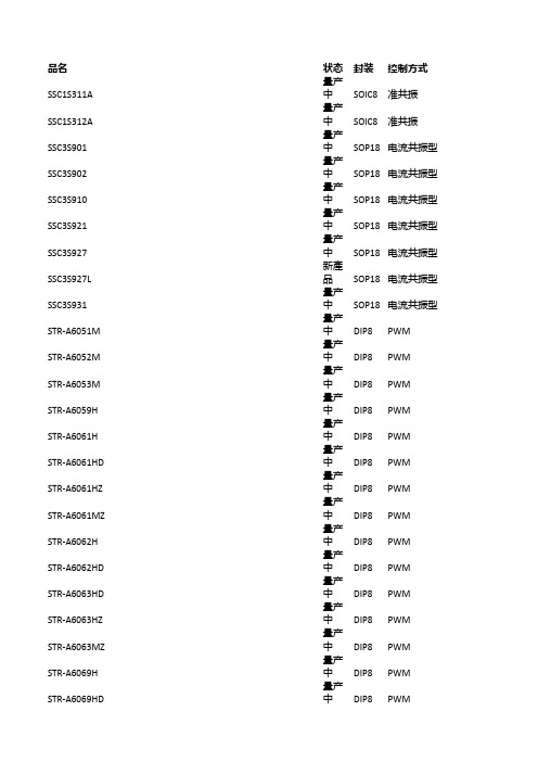
量产 中 量产 中 开发 中 量产 中 量产 中 量产 中 量产 中 量产 中 量产 中 量产 中 量产 中 量产 中 量产 中 量产 中 量产 中 量产 中 量产 中 开发 中 量产 中 量产 中 量产 中
DIP8 DIP8 DIP8 DIP8 DIP8 SOIC8 DIP8 DIP8 DIP8 DIP8 DIP8 DIP8 DIP8 SOIC8 DIP8 DIP8 DIP8 DIP8 DIP8 DIP8 DIP8
32.00 32.00 32.00 35.00 35.00 35.00 35.00 35.00 35.00 35.00 35.00 35.00 35.00 32.00 32.00 32.00 32.00 32.00 32.00 32.00 32.00 32.00 32.00 32.00 32.00
650.00 700.00 700.00 800.00 730.00 730.00 730.00 730.00 730.00 730.00 650.00 650.00 700.00 700.00 650.00 700.00 700.00 700.00 700.00 700.00 700.00
置
23.5
4
MOS内
STR-A6000
置
23.5
4
MOS内
STR-A6000MZ/HZ 置
23.5
4
MOS内
STR-A6000MZ/HZ 置
21
4
MOS内
STR-A6000
置
26.5
2.8
MOS内
STR-A6000
置
26.5
2.8
MOS内
STR-A6000
置
28
2.3
MOS内
Condux-Tesmec RW23 电缆重拴拉杆拖车说明书

CONDUX TESMEC RW23 WINDER SKID
WITH 45,000 LBS. MAXIMUM GVWR
... ... ... ... ... ... ... ... ... ... ... ... ... ... ... ... ... ... ... ... ... ... ... ... ... ... ... ... ... ... ... ... ... ... ... ... ... ... ... ... ... ... ... ... ... ... ... ... ... ... ... ... ... ... ... ... ... ... ... ... ... ... ... ... ...
TESMEC HD FIXED WIRE ROPE REELS ARE INTERCHANGEABLE.
STANDARD EQUIPMENT: TANDEM AXLE, SPRING SUSPENSION, DUAL WHEEL, AIR BRAKE TRAILER. 45,000 GVWR, 235/75R17.5 TIRES, ADJUSTABLE PINTLE HITCH, HYDRAULIC CONTROL STATION WITH DRIPLESS
FMS6363中文资料
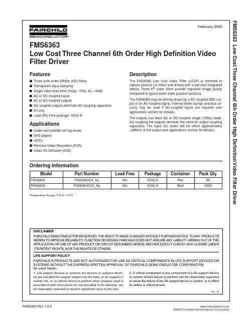
FMS6363 Low Cost Three Channel 6th Order High Definition Video Filter Driver
February 2005
FMS6363 Low Cost Three Channel 6th Order High Definition Video Filter Driver
FMS6363 FMS6363
Temperature Range: 0°C to +70°C
Part Number
FMS6363CS_NL FMS6363CSX_NL
Lead Free
Yes Yes
Package
SOIC-8 SOIC-8
Container
Rail Reel
Pack Qty.
95 25Leabharlann 0Features■ ■ ■ ■ ■ ■ ■ ■ Three sixth-order 30MHz (HD) filters Transparent input clamping Single video load drive (2Vpp, 150Ω, AV = 6dB) AC or DC-coupled inputs AC or DC-coupled outputs DC-coupled outputs eliminate AC-coupling capacitors 5V only Lead (Pb) Free package- SOIC-8
Description
The FMS6363 Low Cost Video Filter (LCVF) is intended to replace passive LC filters and drivers with a low-cost integrated device. Three 6th order filters provide improved image quality compared to typical lower order passive solutions. The FMS6363 may be directly driven by a DC-coupled DAC output or an AC-coupled signal. Internal diode clamps and bias circuitry may be used if AC-coupled inputs are required (see applications section for details). The outputs can drive AC or DC-coupled single (150Ω) loads. DC-coupling the outputs removes the need for output coupling capacitors. The input DC levels will be offset approximately +280mV at the output (see applications section for details).
MMBT3906 40V PNP 小信号晶体管 SOT23 数据手册说明书

MMBT3906Features• Epitaxial Planar Die Construction• Ideal for Medium Power Amplification and Switching • Complementary NPN Type: MMBT3904• Totally Lead-Free & Fully RoHS Compliant (Notes 1 & 2) • Halogen and Antimony Free. “Green” Device (Note 3) • Qualified to AEC-Q101 Standards for High Reliability • PPAP Capable (Note 4)Mechanical Data• Case: SOT23• Case Material: Molded Plastic, “Green” Molding Compound UL Flammability Classification Rating 94V-0 • Moisture Sensitivity: Level 1 per J-STD-020 • Terminals: Finish—Matte Tin Plated Leads, Solderable per MIL-STD-202, Method 208 •Weight: 0.008 grams (Approximate)Ordering Information (Notes 4 & 5)Product Status Compliance Marking Reel Size (inches)Tape Width (mm)Quantity per ReelMMBT3906-7-F Active AEC-Q101 K3N 7 8 3000 MMBT3906Q-7-F Active Automotive K3N 7 8 3000 MMBT3906Q-13-F Active Automotive K3N 13 8 10,000 MMBT3906-13-FActive AEC-Q101 K3N 13 8 10,000Notes:1. No purposely added lead. Fully EU Directive 2002/95/EC (RoHS), 2011/65/EU (RoHS 2) & 2015/863/EU (RoHS 3) compliant.2. See https:///quality/lead-free/ for more information about Diodes Incorporated’s definitions of Halogen- and Antimony-free, "Green" and Lead-free.3. Halogen- and Antimony-free "Green” products are defined as those which contain <900ppm bromine, <900ppm chlorine (<1500ppm total Br + Cl) and <1000ppm antimony compounds.4. Automotive products are AEC-Q101 qualified and are PPAP capable. Refer to https:///quality/.5. For packaging details, go to our website at /products/packages.html.Marking InformationDate Code KeyYear 2015 2016 2017 2018 2019 2020 2021 2022 CodeC DE F G HI JTop ViewSOT23Device SymbolTop View Pin-OutK3NY MK3N = Product Type Marking Code YM = Date Code Marking Y or Y = Year (ex: E= 2017)M or M = Month (ex: 9 = September)Absolute Maximum Ratings(@T A = +25°C, unless otherwise specified.)Thermal Characteristics(@T A = +25°C, unless otherwise specified.)Characteristic Symbol Value UnitPower Dissipation (Note 6)P D310mW (Note 7) 350Thermal Resistance, Junction to Ambient (Note 6)RϴJA403°C/W (Note 7) 357Thermal Resistance, Junction to Leads (Note 8) RϴJL350 °C/W Operating and Storage Temperature Range T J,T STG-55 to +150 °CNotes: 6. For a device mounted on minimum recommended pad layout 1oz copper that is on a single-sided FR4 PCB; the device is measured under still air conditions while operating in a steady-state.7. Same as Note 6 except the device is mounted on 15 mm × 15mm 1oz copper.8. Thermal resistance from junction to solder-point (at the end of the leads).9. Refer to JEDEC specification JESD22-A114 and JESD22-A115.Thermal Characteristics and Derating InformationTransient Therm al Im pedancePulse Width (s)Pulse Power DissipationPulse Width (s)MElectrical Characteristics(@T A = +25°C, unless otherwise specified.)Note: 10. Measured under pulsed conditions. Pulse width ≤ 300µs. Duty cycle ≤ 2%.Typical Electrical Characteristics (@T A = +25°C, unless otherwise specified.)h , D C C U R R E N T G A I NF E I , COLLECTOR CURRENT (mA)Figure 1 Typical DC Current Gainvs. Collector CurrentC V , C O L L E C T O R -E M I T T E R S A T U R A T I O N V O L T A G E (V )C E (S A T )I , COLLECTOR CURRENT (mA)Figure 2 Typical Collector-Emitter Saturation Voltagevs. Collector CurrentC 0.1110V , B A S E -E M I T T E R (V )B E (S A T )S A T U R A T I O N V O L T A G E I , COLLECTOR CURRENT (mA)Figure 3 Typical Base-Emitter Saturation Voltagevs. Collector CurrentC 100C A P A C I T A N C E (p F )V , REVERSE VOLTAGE (V)Figure 4 Typical Capacitance Characteristics RPackage Outline DimensionsPlease see /package-outlines.html for the latest version.SOT23SOT23Dim Min Max Typ A 0.37 0.51 0.40 B 1.20 1.40 1.30 C 2.30 2.502.40 D 0.89 1.03 0.915 F 0.45 0.60 0.535 G 1.78 2.05 1.83 H 2.803.00 2.90 J 0.013 0.10 0.05 K 0.890 1.00 0.975 K1 0.903 1.10 1.025 L 0.45 0.61 0.55 L1 0.25 0.55 0.40 M 0.085 0.150 0.110 a 0° 8° -- All Dimensions in mmSuggested Pad LayoutPlease see /package-outlines.html for the latest version.SOT23。
广州金升阳科技有限公司 LS05-13BxxR3 系列 5W 二极管电源模块说明书
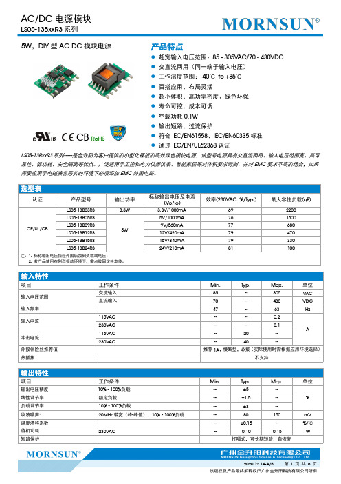
5W,DIY型AC-DC 模块电源CB RoHS产品特点●超宽输入电压范围:85-305VAC/70-430VDC ●交直流两用(同一端子输入电压)●工作温度范围:-40℃to +85℃●百搭应用、布局灵活●超小体积、高功率密度、绿色环保●寿命可控、成本可调●空载功耗0.1W ●输出短路、过流保护●符合IEC/EN61558、IEC/EN60335标准●通过IEC/EN/UL62368认证LS05-13BxxR3系列-----是金升阳为客户提供的小型化裸板的高效绿色模块电源,该型号电源具有交直流两用、输入电压范围宽、高可靠性、低功耗、安全隔离等优点。
广泛适用于工控和电力仪器仪表、智能家居等对体积要求苛刻、并对EMC 要求不高的场合,如果需要应用于电磁兼容恶劣的环境下必须添加EMC 外围电路。
输入特性项目工作条件Min.Typ.Max.单位输入电压范围交流输入85--305VAC 直流输入70--430VDC 输入频率47--63Hz输入电流115V AC ----0.2A230V AC ----0.1冲击电流115V AC --20--230V AC--40--外接保险丝推荐值推荐1A ,慢断型,必接(实际使用时需根据应用环境选择)热插拔不支持输出特性项目工作条件Min.Typ.Max.单位输出电压精度10%-100%负载--±5--%线性调节率额定负载--±1.5--负载调节率10%-100%负载--±3--纹波噪声*20MHz 带宽(峰-峰值),10%-100%负载--80150mV 温度漂移系数--±0.15--%/℃待机功耗230V AC--0.100.15W短路保护打嗝式,可长期短路,自恢复选型表认证产品型号输出功率标称输出电压及电流(Vo/Io)效率(230VAC,%/Typ.)最大容性负载(uF)CE/UL/CBLS05-13B03R3 3.3W3.3V/1000mA 692200LS05-13B05R35W5V/1000mA 761500LS05-13B09R39V/560mA 77680LS05-13B12R312V/420mA 79470LS05-13B15R315V/340mA 79330LS05-13B24R324V/210mA81100注:1.标称输出电压指经外围后加到负载端电压;2.若产品使用在剧烈振动环境下,需点胶固定其本体。
NACHR33K25V6.3X6.3TR13F资料
12
NIC COMPONENTS CORP.
元器件交易网
Surface Mount Aluminum Electrolytic Capacitors
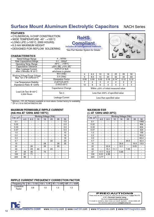
MAXIMUM ESR (Ω AT 120Hz AND 20OC)
Cap. (µF) 0.1 0.22 0.33 0.47 1.0 2.2 3.3 4.7 10 22 33 47 100 220 4.0 17.7 8.31 3.77 6.3 22.6 15.1 10.6 4.98 Working Voltage (Vdc) 10 16 25 35 49.5 26.6 19.9 12.1 9.05 11.1 7.05 5.66 50 1993 906 604 424 199 90.6 60.4 42.4 19.9 -
RoHS Compliant
4 5 0.50 7 12
6.3 8.0 0.30 4 8
10 13 0.22 3 6
16 20 0.16 2 4
25 32 0.14** 2 4
35 44 0.12 2 3
50 63 0.12 2 3
Within ±25% of initial measured value Less than 200% of specified value Less than specified value
PART NUMBER SYSTEM
NACH 100 M 35V
RoHS Compliant 97% Sn (min.), 3% Bi (max.) 330mm (13”) Reel Tape & Reel Size in mm Working Voltage Tolerance Code M=20%, K=10% Capacitance Code in µF, first 2 digits are significant Third digit is no. of zeros, “R” indicates decimal for values under 10µF
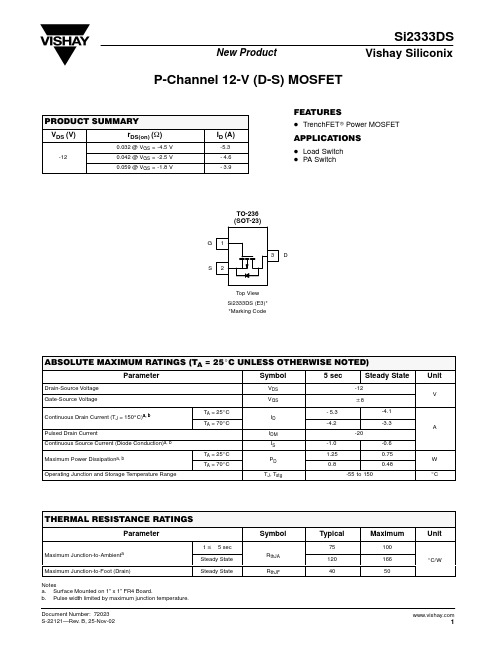
SI2333DS中文资料
20 VGS = 5 thru 2.5 V 2V 16 I D - Drain Current (A) I D - Drain Current (A) 16 20 TC = -55_C 25_C
Vishay Siliconix
Transfer Characteristics
0.4 ID = 140 mA 12 10
Single Pulse Power
0.3 V GS(th) Variance (V)
0.2 Power (W)
8
0.1
6
0.0
4 TA = 25_C
-0.1
2
-0.2 -50
0 -25 0 25 50 75 100 125 150 0.01 0.1 1 Time (sec) 10 100 600 TJ - Temperature (_C)
元器件交易网
Si2333DS
New Product
Vishay Siliconix
P-Channel 12-V (D-S) MOSFET
PRODUCT SUMMARY
VDS (V)
-12
FEATURES
D TrenchFETr Power MOSFET ID (A)
-5.3 - 4.6 - 3.9
Source-Drain Diode Forward Voltage
20 10 r DS(on) - On-Resistance ( W ) 0.12 0.15
On-Resistance vs. Gate-to-Source Voltage
I S - Source Current (A)
TJ = 150_C TJ = 25_C 1
施耐德布线产品手册
施耐德电气VDI综合布线产品目录ConnectivitySuperior Usability User Delights Actassi系列,细微之处折射出精心思量的痕迹,富有未来感的海洋设计元素,方寸间凸现精致味道,”超强适用性”更将令您体验到智能科技所赋予我们的无穷乐趣:使您的生活更从容让您的工作事半功倍集科技美感与强大功能于一身彰显细致品位生活人群对高品质生活的追求即时的备选方案使您永无后顾之忧Discover the delights of Superior Usability!尽享“超强适用性”的无穷乐趣!Actassi 意味着“共享整个蓝色海洋”。
当您选择 Actassi 系列作为您的结构化布线方案时,您便开始在智能科技的“蓝色海洋”中自由遨游了。
在这里,连接方式完全以用以用户为中心,安全稳定、功能强大,雅致且简便易用。
徜徉其中,您不仅可以感受Actassi 系列最新的产品理念,更可以无穷乐趣!Connectivity连通性Superior Usability超强适用性User Delights用户的无穷乐趣ID-Tracer TM 智能布线方案 -您布线时的理想方向标光纤解决方案 -使您的系统稳如泰山减少了60%的IT 基础设施的安装时间大型动态网络智能布线方案后视图10G 解决方案 -为您的数据传输添翼扩展的数据应用更快的数据传输10G 解决方案操作更简单,更持久耐用严格的线缆安装条件光纤解决方案科技快速发展的今天,要求IT 专业人士面对网络规划和操作时,必须快速地作出反应。
这些IT 专业人士面临的最大挑战,就是为了新建的或新选址的办公室建立大型的IT 基础设施,并考虑到公司重组时网络管理的变化。
在配线架、局域网控制器和软件几个方面,我们的ID-TracerTM 智能布线解决方案可以确保他们在这样的大型动态网络中,实现高效且可靠的远程布线管理。
随着新型依赖IP 的VoIP 、视频流、现场报道与监控等应用程序的不断面世,确保优异的传输速度、可靠性与成本有效性则变得空前重要。
MMBT3904LP 40V NPN 小信号透电器说明书

Features∙BV CEO > 40V∙I C = 200mA High Collector Current ∙P D = 1000mW Power Dissipation∙0.60mm 2 Package Footprint, 13 Times Smaller than SOT23∙0.5mm Height Package Minimizing Off-Board Profile ∙Complementary PNP Type MMBT3906LP∙Totally Lead-Free & Fully RoHS Compliant (Notes 1 & 2)∙Halogen and Antimony Free. "Green" Device (Note 3)∙For automotive applications requiring specific changecontrol (i.e.: parts qualified to AEC-Q101, PPAP capable, and manufactured in IATF 16949 certified facilities), please refer to the related automotive grade (Q-suffix) part. A listing can be found athttps:///products/automotive/automotive-products/.∙This part is qualified to JEDEC standards (as references in AEC-Q101) for High Reliability.https:///quality/product-definitions/Mechanical Data∙Case: X1-DFN1006-3∙Case Material: Molded Pla stic, “Green” Molding Compound .UL Flammability Classification Rating 94V-0∙Moisture Sensitivity: Level 1 per J-STD-020Terminals: Finish − NiPdAu, Solderable per MIL-STD-202,Method 208 ∙Weight: 0.0008 grams (Approximate)2. See https:///quality/lead-free/ for more information about Diodes Incorporated’s definitions of Halogen - and Antimony-free, "Green" and Lead-free.3. Halogen- and Antimony-free "Green” products are defined as those which contain <900ppm bromine, <900ppm chlorine (<1500ppm total Br + Cl) and <1000ppm antimony compounds.4. For packaging details, go to our website at https:///design/support/packaging/diodes-packaging/.Top ViewDevice SchematicBottom ViewX1-DFN1006-3Device SymbolCEBe4Marking InformationAbsolute Maximum Ratings (@T A = +25°C, unless otherwise specified.)(Note 8)Notes: 5. For the device mounted on minimum recommended pad layout 1oz copper that is on a single-sided 1.6mm FR4 PCB; device is measured under still air conditions whilst operating in steady state condition. The entire exposed collector pad is attached to the heatsink.6. Same as Note 5, except the exposed collector pad is mounted on 25mm x 25mm 2oz copper.7. Thermal resistance from junction to solder-point (on the exposed collector pad).8. Refer to JEDEC specification JESD22-A114 and JESD22-A115.1N = Product Type Marking Code1N 1N1N1N1N1N1N1N1N1NTop View Bar Denotes Base and Emitter SideThermal Characteristics0.0010.010.11r (t ), T R A N S I E N T T H E R M A L R E S I S T A N C Et1, PULSE DURATION TIME (sec)Fig. 1 Transient Thermal Resistance1,0001001010.1t1, PULSE DURATION TIME (sec)Fig. 2 Single Pulse Maximum Power DissipationNote: 9. Measured under pulsed conditions. Pulse width ≤ 300µs. Duty cycle ≤ 2%.Typical Electrical Characteristics (@T A = +25°C, unless otherwise specified.)I , COLLECTOR CURRENT (mA)C Fig. 8 Typical Base-Emitter Turn-On Voltage vs. Collector CurrentI , COLLECTOR CURRENT (mA)C Fig. 9 Typical Base-Emitter Saturation Voltagevs. Collector CurrentV , COLLECTOR-EMITTER VOLTAGE (V)CE Fig. 4 Typical Collector Current vs. Collector-Emitter Voltage I , C O L L E C T O R C U R R E N T (A )C I , COLLECTOR CURRENT (mA) CFig. 6 Typical Collector-Emitter Saturation Voltagevs. Collector Current I , COLLECTOR CURRENT (mA) CFig. 5 Typical Collector-Emitter Saturation Voltagevs. Collector Current I , COLLECTOR CURRENT (mA) CFig. 4 Typical DC Current Gain vs. Collector Current 040050350Fig. 3 Fig. 7Fig. 8Package Outline DimensionsPlease see /package-outlines.html for the latest version.X1-DFN1006-3Suggested Pad LayoutPlease see /package-outlines.html for the latest version.X1-DFN1006-3。
FOSAN富信电子 二级管 MM3Z2V0-MM3Z75-产品规格书

Max. 2.15 2.33 2.56 2.9 3.2 3.5 3.8 4.1 4.6 5.0 5.4 6.0 6.6 7.2 7.9 8.7 9.6 10.6 11.6 12.7 14.1 16.2 17.1 19.1 21.2 23.3 25.6 28.9 32 35 38 41 46 50 54 60 66 72 79
结温和储藏温度
Symbol 符号 PD(Ta=25℃) VF(@ IF=10mA)
VZ RθJA TJ,Tstg
Max 最大值 300 0.9
2.0-75 417
Unit 单位 mW V V ℃/W
150℃,-55to+150℃
■Electrical Characteristics 电特性 (TA=25℃ unless otherwise noted 如无特殊说明,温度为 25℃)
3H
安徽富信半导体科技有限公司
ANHUI FOSAN SEMICONDUCTOR TECHNOLOGY CO. , LTD.
MM3Z2V0-MM3Z75
■Typical Characteristic Curve 典型特性曲线
Figure 1: Power Derating Curve
■Dimension 外形封装尺寸
VR (V)
Marking
0.5
B0
0.7
C0
1
1C
1
1D
1
1E
1
1F
1
11M
1
1N
2
1P
3
1R
4
1X
5
1Y
6
1Z
7
2A
7
2B
8
2C
STP3NK90ZFP中文资料

1/13November 2002This is preliminary information on a new product now in development or undergoing evaluation.Details are subject to change without notice.STP3NK90Z -STP3NK90ZFP STD3NK90Z -STD3NK90Z-1N-CHANNEL 900V -4.1Ω -3A TO-220/TO-220FP/DPAK/IPAKZener-Protected SuperMESH™Power MOSFETTYPICAL R DS (on)=4.1ΩEXTREMELY HIGH dv/dt CAPABILITY 100%AVALANCHE TESTED GATE CHARGE MINIMIZEDVERY LOW INTRINSIC CAPACITANCESVERY GOOD MANUFACTURING REPEATIBILITYDESCRIPTIONThe SuperMESH™series is obtained through an extreme optimization of ST’s well established strip-based PowerMESH™layout.In addition to pushing on-resistance significantly down,special care is tak-en to ensure a very good dv/dt capability for the most demanding applications.Such series comple-ments ST full range of high voltage MOSFET s in-cluding revolutionary MDmesh™products.APPLICATIONSHIGH CURRENT,HIGH SPEED SWITCHING IDEAL FOR OFF-LINE POWER SUPPLIES,ADAPTORS AND PFC LIGHTINGORDERING INFORMATIONTYPE V DSS R DS(on)I D Pw STP3NK90Z STP3NK90ZFP STD3NK90Z STD3NK90Z-1900V 900V 900V 900V<4.8Ω<4.8Ω<4.8Ω<4.8Ω3A 3A 3A 3A90W 25W 90W 90WSALES TYPE MARKING PACKAGE PACKAGINGSTP3NK90Z P3NK90Z TO-220TUBE STP3NK90ZFP P3NK90ZFP TO-220FP TUBE STD3NK90ZT4D3NK90Z DPAK TAPE &REELSTD3NK90Z-1D3NK90ZIPAKTUBESTP3NK90Z -STP3NK90ZFP -STD3NK90Z -STD3NK90Z-12/13ABSOLUTE MAXIMUM RATINGS( )Pulse width limited by safe operating area(1)I SD ≤3A,di/dt ≤200A/µs,V DD ≤V (BR)DSS ,T j ≤T JMAX.(*)Limited only by maximum temperature allowedTHERMAL DATAAVALANCHE CHARACTERISTICSGATE-SOURCE ZENER DIODEPROTECTION FEATURES OF GATE-TO-SOURCE ZENER DIODESThe built-in back-to-back Zener diodes have specifically been designed to enhance not only the device’s ESD capability,but also to make them safely absorb possible voltage transients that may occasionally be applied from gate to source.In this respect the Zener voltage is appropriate to achieve an efficient and cost-effective intervention to protect the device’s integrity.These integrated Zener diodes thus avoid the usage of external components.SymbolParameterValueUnitSTP3NK90ZSTP3NK90ZFPSTD3NK90Z STD3NK90Z-1V DS Drain-source Voltage (V GS =0)900V V DGR Drain-gate Voltage (R GS =20k Ω)900V V GS Gate-source Voltage±30V I D Drain Current (continuous)at T C =25°C 33(*)3A I D Drain Current (continuous)at T C =100°C 1.89 1.89(*) 1.89A I DM ( )Drain Current (pulsed)1212(*)12A P TOT Total Dissipation at T C =25°C 902590W Derating Factor0.720.20.72W/°C V ESD(G-S)Gate source ESD(HBM-C=100pF,R=1.5K Ω)4000V dv/dt (1)Peak Diode Recovery voltage slope 4.5V/ns V ISO Insulation Withstand Voltage (DC)-2500-V T j T stgOperating Junction Temperature Storage Temperature-55to 150°CTO-220TO-220FPDPAK IPAK Rthj-case Thermal Resistance Junction-case Max 1.3851.38°C/W Rthj-ambThermal Resistance Junction-ambient Max62.5100°C/W T lMaximum Lead Temperature For Soldering Purpose300°CSymbol ParameterMax ValueUnit I AR Avalanche Current,Repetitive or Not-Repetitive (pulse width limited by T j max)3A E ASSingle Pulse Avalanche Energy(starting T j =25°C,I D =I AR ,V DD =50V)180mJSymbol ParameterTest ConditionsMin.Typ.Max.Unit BV GSOGate-Source Breakdown VoltageIgs=±1mA (Open Drain)30V3/13STP3NK90Z -STP3NK90ZFP -STD3NK90Z -STD3NK90Z-1ELECTRICAL CHARACTERISTICS (T CASE =25°C UNLESS OTHERWISE SPECIFIED)ON/OFFDYNAMICSWITCHING ONSWITCHING OFFSOURCE DRAIN DIODENote: 1.Pulsed:Pulse duration =300µs,duty cycle 1.5%.2.Pulse width limited by safe operating area.3.C oss eq.is defined as a constant equivalent capacitance giving the same charging time as C oss when V DS increases from 0to 80%V DSS .Symbol ParameterTest ConditionsMin.Typ.Max.Unit V (BR)DSS Drain-sourceBreakdown Voltage I D =1mA,V GS =0900V I DSS Zero Gate VoltageDrain Current (V GS =0)V DS =Max RatingV DS =Max Rating,T C =125°C 150µA µA I GSS Gate-body Leakage Current (V DS =0)V GS =±30V±10µA V GS(th)Gate Threshold Voltage V DS =V GS ,I D =50µA 33.754.5V R DS(on)Static Drain-source On ResistanceV GS =10V,I D =1.5A4.14.8ΩSymbol ParameterTest ConditionsMin.Typ.Max.Unit g fs (1)Forward Transconductance V DS =15V ,I D =1.5A2.7S C iss C oss C rss Input Capacitance Output Capacitance Reverse Transfer Capacitance V DS =25V,f =1MHz,V GS =05906313pF pF pF C oss eq.(3)Equivalent Output CapacitanceV GS =0V,V DS =0V to 400V34pFSymbol ParameterTest ConditionsMin.Typ.Max.Unit t d(on)t r Turn-on Delay Time Rise TimeV DD =450V,I D =1.5A R G =4.7ΩV GS =10V(Resistive Load see,Figure 3)187ns ns Q g Q gs Q gdTotal Gate Charge Gate-Source Charge Gate-Drain ChargeV DD =720V,I D =3A,V GS =10V22.74.212nC nC nCSymbol ParameterTest ConditionsMin.Typ.Max.Unit t d(off)t f Turn-off Delay Time Fall TimeV DD =720V,I D =1.5A R G =4.7ΩV GS =10V(Resistive Load see,Figure 3)4518ns ns t r(Voff)t f t cOff-voltage Rise Time Fall TimeCross-over TimeV DD =450V,I D =3A,R G =4.7Ω,V GS =10V(Inductive Load see,Figure 5)14.51516ns ns nsSymbol ParameterTest ConditionsMin.Typ.Max.Unit I SD I SDM (2)Source-drain CurrentSource-drain Current (pulsed)312A A V SD (1)Forward On Voltage I SD =3A,V GS =0 1.6V t rr Q rr I RRMReverse Recovery Time Reverse Recovery Charge Reverse Recovery CurrentI SD =3A,di/dt =100A/µs V DD =100V,T j =150°C (see test circuit,Figure 5)5102.28.7ns µC ASTP3NK90Z-STP3NK90ZFP-STD3NK90Z-STD3NK90Z-14/13Output Characteristics5/13STP3NK90Z -STP3NK90ZFP -STD3NK90Z -STD3NK90Z-1STP3NK90Z -STP3NK90ZFP -STD3NK90Z -STD3NK90Z-16/13Maximum Avalanche Energy vsTemperatureSource-drain Diode ForwardCharacteristicsNormalized BVDSS vs Temperature7/13STP3NK90Z -STP3NK90ZFP -STD3NK90Z -STD3NK90Z-1Fig.5:Test Circuit For Inductive Load Switching And Diode Recovery TimesFig.4:Gate Charge test CircuitFig.2:Unclamped Inductive WaveformFig.1:Unclamped Inductive Load TestCircuitFig.3:Switching Times Test Circuit For ResistiveLoadSTP3NK90Z-STP3NK90ZFP-STD3NK90Z-STD3NK90Z-18/13STP3NK90Z-STP3NK90ZFP-STD3NK90Z-STD3NK90Z-19/13STP3NK90Z-STP3NK90ZFP-STD3NK90Z-STD3NK90Z-110/13STP3NK90Z-STP3NK90ZFP-STD3NK90Z-STD3NK90Z-111/13STP3NK90Z -STP3NK90ZFP -STD3NK90Z -STD3NK90Z-112/13TAPE AND REEL SHIPMENT (suffix ”T4”)*TUBE SHIPMENT (nosuffix)*DPAK FOOTPRINT *on sales typeDIM.mm inch MIN.MAX.MIN.MAX.A 33012.992B 1.50.059C 12.813.20.5040.520D 20.20.795G 16.418.40.6450.724N 501.968T22.40.881BASE QTY BULK QTY 25002500REEL MECHANICAL DATADIM.mm inch MIN.MAX.MIN.MAX.A0 6.870.2670.275B010.410.60.4090.417B112.10.476D 1.5 1.60.0590.063D1 1.50.059E 1.65 1.850.0650.073F 7.47.60.2910.299K0 2.55 2.750.1000.108P0 3.9 4.10.1530.161P17.98.10.3110.319P2 1.9 2.10.0750.082R 40 1.574W15.716.30.6180.641TAPE MECHANICAL DATAAll dimensions are in millimetersAll dimensions are in millimetersSTP3NK90Z-STP3NK90ZFP-STD3NK90Z-STD3NK90Z-1 Information furnished is believed to be accurate and reliable. However, STMicroelectronics assumes no responsibility for the consequences of use of such information nor for any infringement of patents or other rights of third parties which may result fromits use. No license is granted by implication or otherwise under any patent or patent rights of STMicroelectronics. Specifications mentioned in this publication are subject to change without notice. This publication supersedes and replaces all information previously supplied. STMicroelectronics products are not authorized for use as critical components in life support devices orsystems without express written approval of STMicroelectronics.© The ST logo is a registered trademark of STMicroelectronics© 2002 STMicroelectronics - Printed in Italy - All Rights ReservedSTMicroelectronics GROUP OF COMPANIESAustralia - Brazil - Canada - China - Finland - France - Germany - Hong Kong - India - Israel - Italy - Japan - Malaysia - Malta - MoroccoSingapore - Spain - Sweden - Switzerland - United Kingdom - United States.© 13/13。
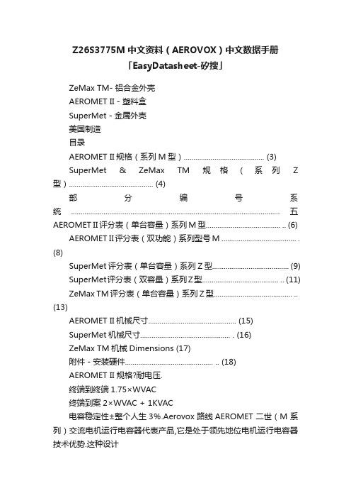
Z26S3775M中文资料(AEROVOX)中文数据手册「EasyDatasheet-矽搜」
Z26S3775M中文资料(AEROVOX)中文数据手册「EasyDatasheet-矽搜」ZeMax TM- 铝合金外壳AEROMET II - 塑料盒SuperMet - 金属外壳美国制造目录AEROMET II规格(系列M型) (3)SuperMet & ZeMax TM规格(系列Z 型) (4)部分编号系统.............................................................................................................五AEROMET II评分表(单台容量)系列M型....................................... .. (6) AEROMET II评分表(双功能)系列型号M ....................................... .(8)SuperMet评分表(单台容量)系列Z型 (9)SuperMet评分表(双容量)系列Z型........................................ .. (11) ZeMax TM评分表(单台容量)系列Z型......................................... ..(13)AEROMET II机械尺寸 (15)SuperMet机械尺寸............................................... . (16)ZeMax TM机械Dimensions (17)附件 - 安装硬件.............................................. .. (18)AEROMET II 规格?耐电压.终端到终端1.75×WVAC终端到案2×WVAC + 1KVAC电容稳定性±整个人生3%.Aerovox 路线AEROMET 二世(M 系列)交流电机运行电容器代表产品,它是处于领先地位电机运行电容器技术优势.这种设计采用绝缘塑胶外壳,额定UL94V-, and a UL Recognized internal pressure interrupter,其中达到或超过传统表现金属外壳替代品.在无腐蚀塑料外壳省去涂漆钢或铝情况下对于室外应用.此外,接地不必要塑料外壳.特征?无腐蚀性,阻燃塑料壳体UL 94V-?.?单,双额定值.?可方便整体安装选项安装.每个电容器充满Aerovox 专利60000小时运行寿命.Supernol 电介液.这种液体是从发自清除金属化聚丙烯薄膜.环境安全和兼容组合?专利压力灭弧室是UL 810成分,提高电容器性能.该认可.流体抑制电晕降解效果获得一致结果全自动装配金属化膜边缘,并改善热传递,环防护专利非PCB 导致优异电容稳定性和长期Supernol 液.长期可靠性.?所有AEROMET II 电容达到稳定EIA RS-186-3E 状态测试要求.所有AEROMET II 电容都可以用时间和成本节约AeroMount 系统.触点厂家触点厂家对于需要reycled 了解详细信息.EIA RS-186-2E 湿度测试要求(Tropi-认证证书UL 文件号E51176CSA 文件号058450VDE 认证可用咨询厂家CAL 条件).应用窗式空调单元式空调电动汽车风扇与鼓风机Pumps 洗衣房设备除湿机压缩机炉电气特性温度范围:-40?+ 70℃.电容范围3至80μF.电容公差±10%.电压范围240至440 VAC,60赫兹.损耗因数0.1%以下@ 60赫兹和25℃.绝缘电阻1000MΩ每μF.SuperMet & ZeMax TM 技术指标特征可根据金属外壳(铝合金外壳请求- 请联系工厂)SuperMet ? ZeMax TM 只圆形铝合金外壳 -?只有SuperMet - 椭圆形表壳选项?单和双额定值 - 双额定值在SuperMet 仅TM 所有SuperMet 和ZEMAX 电容集成?60000小时使用寿命.UL 认证压敏灭弧删除?电容稳定性±整个人生3%电容器从电路在生命尽头.自清除金属化聚丙烯薄膜.?专利压力灭弧符合UL810每个电容器填充有环氧化Soybeanoil要求.电介液.大豆油已被证明可靠性环防护专利非PCB 在几个过去几十年.大豆油是环氧大豆油.环防护和可生物降解.该大豆油防护护金属化膜不受腐蚀,认证证书助剂传热,并有助于抑制降解电晕效应,这可能导致否则prema-UL 和CUL 文件编号E51176TURE 故障.专有加工真空和CE - 向厂家咨询热循环,确防护完全去除水分,VDE - 咨询工厂造成优异电容稳定性和长期可靠性.Aerovox 路线SuperMet 和ZEMAX TM 电容器利用最先进金属化聚丙烯薄膜技术状态.这款最新设计材料结合领先设计技术,具有40多年电容经验.应用电气特性温度范围:-40?+ 70℃.电容范围3至80μF.电容公差±10%.电压范围240至480 VAC,60赫兹.损耗因数0.1%以下@ 60赫兹和25℃.绝缘电阻千M ●μF.耐电压.期限至足月1.75×WVAC期限到案2×WVAC + 1KVAC 窗式空调单元式空调电动汽车风扇与鼓风机Pumps 洗衣房设备除湿机4部分编号系统M23P3725M00 X X产品系列M= AeroMet IIZ= SuperMet & ZeMax TM机箱样式22= 1?"圆23= 1.75"圆24= 2.0"圆26= 2?"圆工厂代码50= 1.25"椭圆形42= 1?"椭圆形64= 1.75"椭圆形62= 2.0"椭圆形注入P= Supernol(M系列)S= SuperSoy(Z系列)电压编码电压第一个两位数24= 240 V交流33= 330 V交流37= 370 V交流44= 440 V交流48= 480 V交流60= 600 Vac电容值(μF额定值)25= 25 μF03= 3 μF)AeroMet II00=单额定值XX=μF价值双额定值SuperMet特别特点额定值特征M=指示N=奇电压或电容值W=双额定值5。
BFR92A中文资料

1997 Oct 29
2
元器件交易网
Philips Semiconductors
Product specification
NPN 5 GHz wideband transistor
THERMAL CHARACTERISTICS SYMBOL Rth j-s Note 1. Ts is the temperature at the soldering point of the collector pin. CHARACTERISTICS Tj = 25 °C unless otherwise specified. SYMBOL ICBO hFE Cc Ce Cre fT GUM PARAMETER collector leakage current DC current gain collector capacitance emitter capacitance feedback capacitance transition frequency maximum unilateral power gain (note 1) CONDITIONS IE = 0; VCB = 10 V IC = 15 mA; VCE = 10 V; see Fig.4 IE = ie = 0; VCB = 10 V; f = 1 MHz; see Fig.5 IC = ic = 0; VEB = 10 V; f = 1 MHz IC = ic = 0; VCE = 10 V; f = 1 MHz IC = 15 mA; VCE = 10 V; f = 500 MHz; see Fig.6 IC = 15 mA; VCE = 10 V; f = 1 GHz; Tamb = 25 °C IC = 15 mA; VCE = 10 V; f = 2 GHz; Tamb = 25 °C F noise figure IC = 5 mA; VCE = 10 V; f = 1 GHz; Γs = Γopt; Tamb = 25 °C; see Figs 13 and 14 IC = 5 mA; VCE = 10 V; f = 2 GHz; Γs = Γopt; Tamb = 25 °C; see Figs 13 and 14 VO d2 Notes output voltage second order intermodulation distortion notes 2 and 3 notes 2 and 4; see Fig.16 MIN. − 40 − − − − − − − TYP. − 90 0.6 1.2 0.35 5 14 8 2.1 PARAMETER CONDITIONS VALUE 260
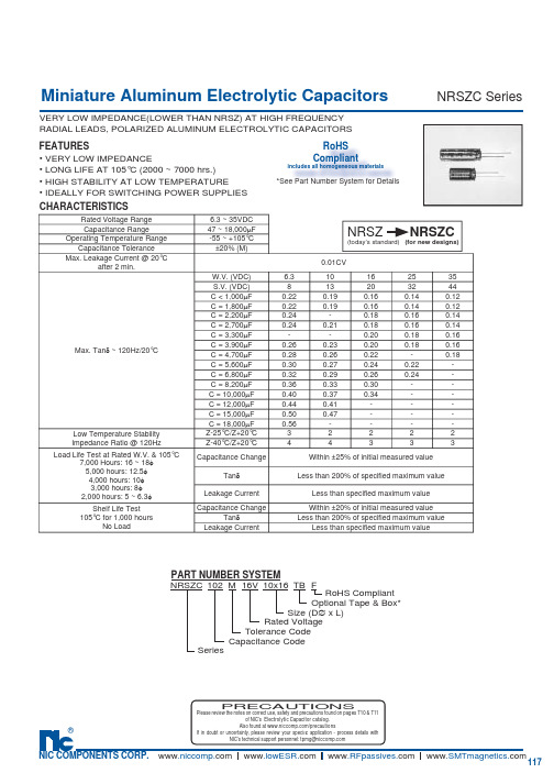
NRSZC391M6.3V5X11TBF中文资料
VERY LOW IMPEDANCE(LOWER THAN NRSZ) AT HIGH FREQUENCY • VERY LOW IMPEDANCE• LONG LIFE AT 105°C (2000 ~ 7000 hrs.)• HIGH STABILITY AT LOW TEMPERATURE• IDEALLY FOR SWITCHING POWER SUPPLIES FEATURESCHARACTERISTICSMiniature Aluminum Electrolytic Ca p ac i t orsNRSZC SeriesRADIAL LEADS, POLARIZED ALU M I N UM ELEC T RO L YT I C CAPACITORS PART NUMBER SYSTEMSize (D ∅ x L)NRSZC 102M 16V 10x16SeriesCapacitance CodeTolerance Code Rated Voltage RoHS Compliant FTB Optional Tape & Box*NRSZ NRSZC(today’s standard) (for new designs)PRECAUTIONSPlease review the notes on correct use, safety and precautions found on pages T10 & T11of NIC’s Electrolytic Capacitor catalog . Rated Voltage Range 6.3 ~ 35VDC Capacitance Range47 ~ 18,000µF Operating Temperature Range-55 ~ +105°C Capacitance Tolerance ±20% (M)Max. Leakage Current @ 20°Cafter 2 min.0.01CVMax. Tan δ ~ 120Hz/20°CW.V. (VDC) 6.310162535S.V. (VDC)813203244C < 1,000µF 0.220.190.160.140.12C = 1,800µF 0.220.190.160.140.12C = 2,200µF 0.24-0.180.160.14C = 2,700µF 0.240.210.180.160.14C = 3,300µF --0.200.180.16C = 3,900µF 0.260.230.200.180.16C = 4,700µF 0.280.260.22-0.18C = 5,600µF 0.300.270.240.22-C = 6,800µF 0.320.290.260.24-C = 8,200µF 0.360.330.30--C = 10,000µF 0.400.370.34--C = 12,000µF 0.440.41---C = 15,000µF 0.500.47---C = 18,000µF 0.56----Low Temperature Stability Impedance Ratio @ 120Hz Z-25°C/Z+20°C 32222Z-40°C/Z+20°C 44333Load Life Test at Rated W.V. & 105°C7,000 Hours: 16 ~ 18φ5,000 hours: 12.5φ4,000 hours: 10φ3,000 hours: 8φ2,000 hours: 5 ~ 6.3φCapacitance ChangeWithin ±25% of initial measured value Tan δLess than 200% of specifi ed maximum valueLeakage Current Less than specifi ed maximum value Shelf Life Test 105°C for 1,000 hoursNo LoadCapacitance ChangeWithin ±20% of initial measured value Tan δLess than 200% of specifi ed maximum valueLeakage CurrentLess than specifi ed maximum valueRoHS Compliantincludes all homogeneous materials*See Part Number System for DetailsMiniature Aluminum Electrolytic Ca p ac i t ors NRSZC SeriesMiniature Aluminum Electrolytic Ca p ac i t ors NRSZC SeriesMiniature Aluminum Electrolytic Ca p ac i t orsNRSZC SeriesF ± 0.5= L < 20mm = 1.5mm, L > 20mm = 2.0mm。
SOFNG 内存卡连接器(型号:SD-006M)说明书

過回焊爐前後對比 [coplanarity]
Result
OK OK OK OK OK OK OK OK OK OK
Sample NO. 11 # 12 # 13 # 14 # 15 # 16 # 17 # 18 # 19 # 20 #
實驗比例
Before
0.042 0.034 0.038 0.045 0.043 0.037 0.047 0.038 0.048 0.038
實驗結果
產品在錫爐浸泡 4.9 秒後,焊錫面積大於 95%。
試驗數:5 PCS
實驗比例 不良描述
無異常現象
不良數:0 PCS
PAGE:7.
4.焊錫熱反應實驗[數據 PAGE:6.]:
實驗目的
證實產品抵抗焊接高溫可靠性與參數相符
實驗設備
回焊爐、測量儀
實驗條件
回焊盧溫度:240±5℃ 最高溫區 200℃MIN. 60sec.MAX.
Description Card Detect/Date Line[Bit 3]
Command/Response Supply voltage ground
Supply voltage Clock
Supply voltage ground Date Line [Bit 0] Date Line [Bit 1] Date Line [Bit 2]
After
0.066 0.059 0.051 0.063 0.062 0.059 0.068 0.052 0.067 0.062
PAGE:5.
Pin8
6.25 7.3 7.26 6.46 7.61 6.39 7.54 6.75 6.96 10.47 6.22 7.36 7.24 6.48 7.56 6.43 7.59 6.95 7.91 10.45 6.38 7.23 7.45 6.96 7.48 6.68 8.26 7.59 6.18 10.11
VORTEX86SX中文资料
Vortex86SX 32-BIT x86 Embedded SoC Brief Datasheet (v1.001)Vortex86SX32-Bit x86 Embedded SoC CONTENTS1Overview (3)2Features (3)3Block Diagram (4)3.1System Block Diagram (4)3.2Functions Block Diagram (5)3.3PCI Device List (5)4PIN Function List (6)4.1BGA Ball Map (6)4.2Signal Description (7)5Rreference Design Schematic (22)6Package Information (31)Vortex86SX32-Bit x86 Embedded SoC1 OverviewVortex86SX is the x86 SoC (System on Chip) with 0.13 micron process and ultra low power consumption design (less than 1 watt). This comprehensive SoC has been integrated with rich features, such as various I/O (RS-232, Parallel, USB and GPIO), BIOS, WatchDog Timer, Power Management, MTBF counter, LoC (LAN on Chip),JTAG etc., into a 27x27 mm, 581-pin BGA packing single chip.The Vortex86SX is compatible with Win CE, Linux and DOS. It integrates 32KB write through direct map L1 cache, 16-bit ISA bus, PCI Rev. 2.1 32-bit bus interface at 33 MHz, SDRAM, DDR2, ROM controller, IPC (Internal Peripheral Controllers with DMA and interrupt timer/counter included), SPI (Serial Peripheral Interface), Fast Ethernet MAC, FIFO UART, USB2.0 Host and IDE controller into a System-on-Chip (SoC) design.Furthermore, this outstanding Vortex86SX SoC can not only meet the requirements of embedded applications, such as Electronics Billboard, Firewall Router, Industrial Single-Board-Computers, Receipt Printer Controller, Thin Client PC, Auto Vehicle Locator, Finger Print Identification, Web Camera Thin Server, RS232-to-TCP Transmitter. but also can meet the critical temperature demand, spanning from -40 to +85 ℃.2 Featuresx86 Processor Core – 6 stage pipe-lineEmbedded I/D Separated L1 Cache – 16K I-Cache, 16K D-CacheSDRAM/DDRII Control Interface – 16 bits data bus– Support DLL for clock phase auto-adjustion – SDRAM support up to 133MHz – SDRAM support up to 128Mbytes – DDRII support up to 166MHz – DDRII support up to 256Mbytes IDE Controller–Support 2 channels Ultra-DMA 100 (Disk x 4)LPC (Low Pin Count) Bus Interface– Support 2 programable registers to decode LPCaddressMAC Controller x 1 PCI Control Interface–Up to 3 sets PCI master device – 3.3V I/OISA Bus Interface– AT clock programmable– 8/16 Bit ISA device with Zero-Wait-State– Generate refresh signals to ISA interface duringDRAM refresh cycleDMA Controller Interrupt ControllerCounter/Timers– 2 sets of 8254 timer controller– Timer output is 5V tolerance I/O on 2nd Timer MTBF Counter Real Time Clock– Below 2uA power comsuption on Internal Mode(Estimation Value)FIFO UART Port x 5 (5 sets COM Port)– Compatible with 16C550/16C552 – Default internal pull-up– Supports the programmable baud rate generatorwith the data rate from 50 to 460.8K bps– The character options are programmable for 1 startbits; 1, 1.5 or 2 stop bits; even, odd or no parity; 5~8 data bits– Support TXD_En Signal on COM1/COM2–Port 80h output data could be sent to COM1 by software programming Parallel Port x 1– Support SPP/EPP/ECP modeGeneral Chip Selector– 2 sets extended Chip Selector– I/O-map or Memory-map could be configurable – I/O Addressing: From 2 byte to 64K byte –Memory Address: From 512 byte to 4G Byte General Programmable I/O– Supports 40 dedicated programmable I/O pins–Each GPIO pin can be individually configured to be an input/output pinUSB 2.0 Host Support– Supports HS, FS and LS – 4 portPS/2 Keyboard and Mouse Interface Support–Compatible with 8042 controllerRedundant System Support Speaker outEmbedded 256KB Flash– For BIOS storage–The Flash could be disable & use external Flash ROMJTAG Interface supported for S.W. debuggingInput clock – 14.318MHz – 32.768KHz Output clock – 24 MHz – 25 MHzOperating Voltage Range– Core voltage: 1.2 V ~ 1.4V–I/O voltage: 1.8V ± 5% , 3.3 V ± 10 %Operating temperature– -40℃ ~ 85℃Package Type–27x27mm, 581 ball BGAVortex86SX32-Bit x86 Embedded SoC3 Block Diagram3.1 System Block DiagramVortex86SX32-Bit x86 Embedded SoC3.2 Function Block Diagram (Internal)3.3 PCI Device ListDevice# 0 1 2 3 4 567 8 910 1112 13IDSEL AD11 AD12 AD13 AD14 AD15 AD18AD19AD21 AD22 AD23Function 0 NB PCI SLOT1 PCISLOT2 PCISLOT3PCI SLOT4SB MACUSB0 OHCI USB1OHCI IDE Function 1USB0 EHCIUSB1EHCIVortex86SX32-Bit x86 Embedded SoC4 PIN Function List4.1 BGA Ball Map元器件交易网Vortex86SX32-Bit x86 Embedded SoC4.2 Signal DescriptionThis chapter provides a detailed description of Vortex86SX signals. A signal with the symbol ”_n” at the end of itself indicates that this pin is low active. Otherwise, it is high active. The following notations are used to describe the signal types: I Input pin O Output pinOD Output pin with open-drain I/OBi-directional Input/Output pinz System (7 PINs)PIN No.SymbolTypeDescriptionAA26 PWRGOOD IPower-Good Input. This signal comes from Power Good of the power supplyto indicate that the power is available. The Vortex86SX uses this signal to generate reset sequence for the system. AB26 25MOUT O 25MHz Clock output. Y26 XOUT_14.318 O Crystal-out . Frequency output from the inverting amplifier (oscillator).Y25 XIN_14.318 ICrystal-in. 14.318MHz frequency input, within 100 ppm tolerance, to theamplifier (oscillator).AA25 MTBF MTBF Flag output. AB25 CLK24MOUT O 24MHz Clock outputY23 SPEAKER OSpeaker Output. This pin is used to control the Speaker Output and shouldbe connected to the Speakerz SDRAM /DDRII Interface (44 PINs)PIN No.SymbolTypeDescriptionB9 SDRAMCLK OClock output. This pin provides the fundamental timing for the SDRAM /DDRcontroller.A9 SDRAMCLKN OClock output. This pin provides the fundamental timing for the SDRAM /DDRcontroller.D13 RAS_ O Row Address Strobe. When asserted, this signal latches row address onpositive edge of the SDRAM/DDR clock. This signal also allows row accessand pre-charge.E12 CAS_ O Column Address Strobe. When asserted, this signal latches column addresson the positive edge of the SDRAM/DDR clock. This signal also allowscolumn access and pre-charge.C13 WE_ OMemory Write Enable. This pin is used as a write enable for the memorydata bus.B13, E13 CS_[1:0] O Chip Select CS[1:0]. These two pins activate the SDRAM devices. First Bank of SDRAM accepts any command when the CS0_n pin is active low. SecondBank of SDRAM accepts any command when the CS1_n pin is active low.For DDRII, only CS0_n activates the DDR device.B14, D17 DQM[1:0] OData Mask DQM[1:0]. These pins act as synchronized output enables duringread cycles and byte masks during write cycles.E16, D14 DQS[1:0] I/OData Strobe DQS[1:0 for DDR only. Output with write data, input with theread data for source synchronous operation.Vortex86SX32-Bit x86 Embedded SoCF12, D12 BA[1:0]/Strap[17:16] OBank Address BA[1:0]. These pins are connected to SDRAM/DDR as bank address pins.Strap[17:16]. Memory Select, Default pull high. Strap[17]Strap[16] DRAM Select 0 0 SDRAM 0 1 Reserved 1DDR1 1 DDRII (Default)C12 BA[2] OBank Address [2]. These pins are connected to SDRAM/DDR as bankaddress pins.D16, C17, C14, D15, C15, E14, C16, E15, B15, A13, A14, A17, A16, A15, B16,B17MD[15:0] I/OMemory Data MD[15:0]. These pins are connected to the SDRAM/DDR databus. A10 MA[0] O Memory Address MA[0]. Normally, these pins are used as the row andcolumn address for SDRAM/DDR.A11 MA[1]/Strap[1]O Memory Address MA[1]. Normally, these pins are used as the row and column address for SDRAM/DDR.Strap[1]. Pull it high to enable GPIO2. Default pull high. Pull it low to enable Address[31:24].C9 MA[2]O Memory Address MA[2]. Normally, these pins are used as the row andcolumn address for SDRAM/DDR.B10 MA[3] /Strap[3]O Memory Address MA[3]. Normally, these pins are used as the row and column address for SDRAM/DDR.Strap[3]. PLL_TEST_OUT_EN_, Default pull low.Pull it high to enable PLL_TEST_OUT_EN_. Pull it low to disable PLL_TEST_OUT_EN_.C10MA[4] /Strap[4]OMemory Address MA[4]. Normally, these pins are used as the row and column address for SDRAM/DDR.Strap[4]/[10]. SDRAM/DDR clock, Default pull high. Strap[10]Strap[4]SDRAM clock0 0 100MHz0 1 133MHz (Internal default) 1 0 166MHz1 1 200MHzC11,B12,B11 MA[7:5]/Strap[7:5]I/O Memory Address MA[7:5]. Normally, these pins are used as the row and column address for SDRAM/DDR. Strap[7:5] / CPU Clock 3b’000 / Bypass mode3b’001 / SYN_DISABLE_ (CPU clock same to SDRAM Clock) 3b’010 / 233MHz 3b’011 / 266MHz3b’100 / 300MHz (Internal default) 3b’101 / 333MHz 3b’110 / 366MHz 3b’111 / 400MHzF9 MA[8]/Strap[8] I/OMemory Address MA[8]. Normally, these pins are used as the row and column address for SDRAM/DDR. Strap[8]. Pull it high to enable Vortex86SX JTAG. Default internal pull-high.Vortex86SX32-Bit x86 Embedded SoCD11 MA[9]/Strap[9] I/O Memory Address MA[9].Normally, these pins are used as the row and column address for SDRAM/DDR.Strap[9]. Pulled low: 33 PINS is for IDE2.Pulled high: 33 PINS is for COM3/4 and Parallel Port. Default internal pull-high.A12 MA[10]/Strap[10] I/O Memory Address MA[10]. Normally, these pins are used as the row and column address for SDRAM/DDR.Strap[4]/[10]. SDRAM/DDR clock, Default pull low. Strap[10] Strap[4] Memory clock0 0 100MHz0 1 133MHz (Internal default) 1 0 166MHz1 1 200MHzE11 MA[11]/Strap[11] I/OMemory Address MA[11].Normally, these pins are used as the row and column address for SDRAM/DDR.Strap[11]. Pulled low is Internal RTC. Default internal pull-low.Pulled high is External RTCF11,F10 MA[13:12]/Strap[13:12]I/O Memory Address MA[13:12].Normally, these pins are used as the row and column address for SDRAM/DDR.Strap[13:12]. 00 : flash-8bits01 : flash-16bits 11 : Internal SPI. Default internal pull-high.z USB 0, 1, 2, 3 (10 PINs)PIN No. Symbol Type DescriptionN26N25 USB0_DP USB0_DM I/OUniversal Serial Bus Controller 0 Port 0. These are the serial data pair for USB Port 0. 15k Ωpull down resistors are connected to DP and DM internally.M26 M25 USB1_DP USB1_DM I/OUniversal Serial Bus Controller 0 Port 1. These are the serial data pair for USB Port 1. 15k Ωpull down resistors are connected to DP and DM internally.T26 T25 USB2_DP USB2_DM I/OUniversal Serial Bus Controller 1Port 0. These are the serial data pair for USB Port 2. 15k Ωpull down resistors are connected to DP and DM internally.R26 R25USB3_DP USB3_DMI/OUniversal Serial Bus Controller 1 Port 1. These are the serial data pair for USB Port 3. 15k Ω pull down resistors are connected to DP and DM internally.P26 REXT[0]: I Universal Serial Bus Controller 0 External Reference Resistance. 510Ω±10%U26 REXT[1]:I Universal Serial Bus Controller 1 External Reference Resistance. 510Ω±10%z PCI Bus Interface (56 PINs)PIN No. Symbol Type DescriptionB19, B18, C18PREQ_[2:0]IPCI Bus Request. These signals are the PCI bus request signals used as inputs by the internal PCI arbiter.D19, D18 ,C19 PGNT_[2:0] OPCI Bus Grant. These signals are the PCI bus grant output signals generatedby the internal PCI arbiter.D26 PCIRST_ OPCI Reset. This pin is used to reset PCI devices. When it is asserted low, allthe PCI devices will be reset.A19 A18 A20 PCICLK_0PCICLK_1 PCICLK_2O PCI Clock Output. This clock is used by all of the Vortex86SX logic that is inthe PCI clock domain.Vortex86SX32-Bit x86 Embedded SoCC20, B20, A21 A22, A23, A24, A25, B26, D20, E20, C21, B21, C22, B22, C23, B23, E24, E25, E26, H22, G23, F26, F25, H21, G25, J22, G26, H25, H26, J25, J26, H24 AD[31:0] I/OPCI Address and Data. The standard PCI address and data lines. The address is driven with PCI Frame assertion and data is driven or received in the following clocks.B25, B24, G22,F24CBE_[3:0] I/O Bus Command and Byte Enables. During the address phase, C/BE_n[3:0] define the Bus Command. During the data phase, C/BE[3:0]_n define the Byte Enables.C24 FRAME_ I/OPCI Frame . This pin is driven by a PCI master to indicate the beginning andduration of a PCI transaction.C25 IRDY_ I/OPCI Initiator Ready. This pin is asserted low by the master to indicate that it is able to transfer the current data transfer. A data was transferred if bothIRDY_n and TRDY_n are asserted low during the rising edge of the PCI clock.C26 TRDY_ I/OPCI Target Ready . This pin is asserted low by the target to indicate that it is able to receive the current data transfer. A data was transferred if bothIRDY_n and TRDY_n are asserted low during the rising edge of the PCI clock.D24 DEVSEL_ I/ODevice Select. This pin is driven by the devices which have decoded theaddresses belonging to them.D25 STOP_ I/OPCI Stop. This pin is asserted low by the target to indicate that it is unable toreceive the current data transfer.G24 PAR I/OPCI Parity . This pin is driven to even parity by PCI master over the AD[31:0] and C/BE_n[3:0] bus during address and write data phases. It should bepulled high through a weak external pull-up resistor. The target drives parity during data read.H23 INTA_ IPCI INTA_. PCI interrupt input A. It connects to PCI INTA_n when normalmodes of PCI Interrupts are supported.F19 INTB_ IPCI INTB_. PCI interrupt input B. It connects to PCI INTB_n when normalmodes of PCI Interrupts are supported.F20 INTC_ IPCI INTC_. PCI interrupt input C. It connects to PCI INTC_n when normalmodes of PCI Interrupts are supported.E19 INTD_ IPCI INTD_. PCI interrupt input D. It connects to PCI INTD_n when normalmodes of PCI Interrupts are supported.z EXTERNAL SPI/PORT[3-0] Interface (4 PINs)PIN No.SymbolTypeDescriptionW21 E_SPI_CS_/GPIO_P3[0] I/OExternal SPI Chip SelectGeneral-Purpose Input/Output P3[0] W22 E_SPI_CLK/GPIO_P3[1] I/OExternal SPI ClockGeneral-Purpose Input/Output P3[1] Y21 E_SPI_DO/GPIO_P3[2] I/OExternal SPI Data OuputGeneral-Purpose Input/Output P3[2] Y22 E_SPI_DI/GPIO_P3[3] I/OExternal SPI Data InputGeneral-Purpose Input/Output P3[3]z ISA Bus Interface ( 87 PINs)PIN No.SymbolType DescriptionAA13 IOCHCK_I I/O Channel Check . Provides the system board with parity (error) information about memory or devices on the I/O channel.AE16, AF16, AD10, AF15, AF14, AE11, AE10, AD12,Y6, AD14, Y4, AA14,SD[15:0]I/OISA high and low byte slot data bus . These are the system data lines.These signals read data and vectors into CPU during memory or I/O read cycles or interrupt acknowledge cycles and outputs data from CPU duringAA16, AC14, Y1,AA7 memory or I/O write cycles.AE8 IOCHRDY_ IISA system ready . This input signal is used to extend the ISA command width for the CPU and DMA cycles. AB8 AEN O ISA address enable . This active high output indicates that the systemaddress is enabled during the DMA refresh cycles.AA3, AA1, AB2, AD2,AA2, AD3, AB7, AE5, AC7, AD6, AC2, AE13, AB11, AA12, AB13 AF12, AC3 SA[16:0] O ISA slot address bus. These signals are high impedance during hold acknowledge.AA9, AD5, AB9 SA[19:17] O ISA slot address bus. ISA slot address bus for 62-pin slot.AC13 SBHE_ O ISA Bus high enable. In master cycle, it is an input polarity signal and isdriven by the master device.AC15, AD13, AE14,AA15, AD15, AB15,AE9 LA[23:17]O ISA latched address bus . These are input signal during ISA master cycle. AF9 MEMR_ O ISA memory read . This signal is an input during ISA master cycle.AE12 MEMW_ O ISA memory write . This signal is an input during ISA master cycle.RST_DRV ODriver Reset . This output signal is driven active during system power up. AF4, AF2,AC8, AF3, AE6, AB14, AE7, AC1, AD7, AD1, AE2IRQ[7:3],IRQ[12:9],IRQ[15:14]I Interrupt request signals . These are interrupt request input signals. AE15, AF11, AA11,Y5, AC9, AD4,AB12 DRQ[7:5], DRQ[3:0] IDMA device request . These are DMA request input signals. AD8 0WS_ IISA zero wait state . This is the ISA device zero-wait state indicator signal.This signal terminates the CPU ISA command immediately. AA10 SMEMR_ OISA system memory read . This signal indicates that the memory read cycle is for an address below 1M byte address. AA8 SMEMW_ OISA system memory write . This signal indicates that the memory write cycle is for an address below 1M byte address. Y2 IOW_ OISA I/O write . This signal is an input during ISA master cycle. AB16 IOR_ OISA I/O read . This signal is an input during ISA master cycle. AF7, AD11, AB10, Y3, AF13, AB3,AD9 DACK_[7:5], DACK_[3:0]O DMA device acknowledge signals . These are DMA acknowledgedemultiplex select signals. Input function is for hardware setting. AF6 REFRESH_ O Refresh cycle indicator . ISA master uses this signal to notify DRAM needsrefresh. During the memory controller's self-acting refresh cycle, M6117Ddrives this signal to the I/O channels.AF10 SYSCLK OSystem Clock Output . This signal clocks the ISA bus. AF5 TC O DMA end of process . This is the DMA channel terminal count indicating signal.AE4 BALE O Bus address latch enable . BALE indicates the presence of a valid address at I/O slots.AE1 MEMCS16_ I ISA 16-bit memory device select indicator signal.AE3 IOCS16_ I ISA 16-bit I/O device select indicator signal.AF8 OSC14M O 14.318MHz clock outz Chip Selection Interface (3 PINs)PIN No. Symbol Type DescriptionAC16 GPCS0_ OISA Bus Chip Select 0. This pin is the chip select for ISA bus. AD16 GPCS1_ OISA Bus Chip Select 1. This pin is the chip select for ISA bus. G21 ROMCS_/SPICS_ O ROM Chip Select. This pin is used as a ROM chip select. SPI Chip Select. This pin is used as SPI flash chip select.z Redundant (4 PIN) PIN No. Symbol Type DescriptionU21 EXTSYSFAILIN_ IExternal system fail input . This pin is the system fail in for redundant. U22 SYSFAILOUT_ OSystem fail output . This pin is the system fail out for redundant. V22 EXT_SWITCH_FAIL_ IExternal switch fail . This pin is the switch input for redundant. V21 EXT_GPCS_ IExternal GPCS input . This pin is the GPCS in for redundant.z KBD/MOUSE Interface (4 PINs) PIN No. Symbol Type DescriptionV13 KBCLK/KBRST I/O Keyboard Clock . This pin is keyboard clock when used internal 8042. Keyboard Reset . This pin is Keyboard reset when used external 8042.V16 KBDAT/A20GATE I/O Keyboard Data . This pin is keyboard data when used internal 8042. Address Bit 20 Mask . This pin is A20 mask when used external 8042.V14 MSCLK I/OMouse Clock . This pin is mouse clock when used internal 8042. V15MSDAT I/O Mouse Data . This pin is mouse data when used internal 8042.z RTC/PORT3[7-4] Interface (7 PINs) PIN No.Symbol Type Description N21 RTC_AS/GPIO_P3[7]I/O RTC Address Strobe. This pin is used as the RTC Address Strobe and should be connected to the RTC. General-Purpose Input/Output GPIO P3[7]. P22 RTC_RD_/GPIO_P3[6]I/O RTC Read Command. This pin is used as the RTC Read Command and should be connected to the RTC. General-Purpose Input/Output GPIO P3[6]. T21 RTC_WR_/GPIO_P3[5]I/O RTC Write Command. This pin is used as the RTC Write Command and should be connected to the RTC. General-Purpose Input/Output GPIO P3[5]. R22RTC_IRQ8_/GPIO_P3[4] I/O RTC Interrupt Input. This pin is used as the RTC Interrupt input.General-Purpose Input/Output GPIO P3[4]. T22RTC_PS I RTC Battery Power Sense. V25RTC_XOUT O Crystal-out . V26RTC_XIN ICrystal-in. z COM1/PORT4 Interface (9 PINs)PIN No. Symbol Type DescriptionAE21 SIN1/GPIO_P4[4] I/OReceive Data. FIFO UART receiver serial data input signal.General-Purpose Input/Output GPIO port4 [4].AE22 SOUT1/GPIO_P4[1] I/OTransmit Data. FIFO UART transmitter serial data output from the serial port.General-Purpose Input/Output GPIO port4 [1].AF22 RTS1/GPIO_P4[2] I/ORequest to Send. Active low Request to Send output for UART port.A handshake output signal notifies the modem that the UART is ready totransmit data. This signal can be programmed by writing to bit 1 of ModemControl Register (MCR). The hardware reset will clear the RTS_n signal to be inactive mode (high). It is forced to be inactive during the loop-modeoperation.General-Purpose Input/Output GPIO port4 [2].AE23 CTS1/GPIO_P4[7] I/O Clear to Send. This active low input for the primary and secondary serialports. A handshake signal notifies the UART that the modem is ready toreceive data. The CPU can monitor the status of the CTS_n signal by readingbit 4of Modem Status Register (MSR). A CTS_n signal states the changefrom low to high after the last MSR read sets bit 0 of the MSR to a “1”. If bit 3 of the Interrupt Enable Register is set, the interrupt is generated when CTS_nchanges the state. The CTS_n signal has no effect on the transmitter.Note: Bit 4 of the MSR is the complement of CTS_n.General-Purpose Input/Output GPIO port4 [7].AF23 DSR1/GPIO_P4[6] I/O Data Set Ready. This active low input is for the UART ports. A handshakesignal notifies the UART that the modem is ready to establish thecommunication link. The CPU can monitor the status of the DSR_n signal byreading bit5 of the Modem Status Register (MSR). A DSR_n signal states thechange from low to high after the last MSR read sets bit1 of the MSR to a “1”. If bit 3 of the Interrupt Enable Register is set, the interrupt is generated whenDSR_n changes state.Note: Bit 5 of the MSR is the complement of DSR_n.General-Purpose Input/Output GPIO port4 [6].AF24 DCD1/GPIO_P4[0] I/O Data Carrier Detect.This active low input is for the UART ports. A handshakesignal notifies the UART that the carrier signal is detected by the modem. TheCPU can monitor the status of the DCD_n signal by reading bit 7 of theModem Status Register (MSR). A DCD_n signal states the change from low tohigh after the last MSR read sets bit 3 of the MSR to a “1”. If bit 3 of the Interrupt Enable Register is set, the interrupt is generated when DCDJchanges state.Note: Bit 7 of the MSR is the complement of DCD_n.General-Purpose Input/Output GPIO port4 [0].AD22 RI1/GPIO_P4[3] I/O Ring Indicator.This active low input is for the UART ports. A handshakesignal notifies the UART that the telephone ring signal is detected by themodem. The CPU can monitor the status of the RI_n signal by reading bit 6 ofthe Modem Status Register (MSR). An RI_n signal states the change from lowto high after the last MSR read sets bit 2 of the MSR to a “1”. If bit 3 of the Interrupt Enable Register is set, the interrupt is generated when RI_n changesstate.Note: Bit 6 of the MSR is the complement of RI_n.General-Purpose Input/Output GPIO port4 [3].AD23 DTR1/GPIO_P4[5] I/OData Terminal Ready. This is an active low output for the UART port. Ahandshake output signal signifies the modem that the UART is ready toestablish data communication link. This signal can be programmed by writingto bit 0 of Modem Control Register (MCR). The hardware reset will clear the DTR_n signal to be inactive during the loop-mode operation.General-Purpose Input/Output GPIO port4 [5].AD21 TXD_EN1 I/O COM1 TX Status. This pin will be high when COM1 is trnamitting.z COM2/PWM Interface (9 PINs) PIN No. Symbol Type DescriptionAF25 SIN2/PWM2CLK I COM2 Receive Data. FIFO UART receiver serial data input signal.PWM Timer2 Clock. This pin is PWM timer2 external clock input when SBregister C0h bit2 is 1 (PINs for PWM).AE24 SOUT2/PWM0OUT O COM2 Transmit Data. FIFO UART transmitter serial data output from theserial port.PWM Timer0 Output. This pin is PWM timer0 output when SB register C0hbit2 is 1 (PINs for PWM).AD25 RTS2/PWM1OUT O Request to Send. Active low Request to Send output for UART port.A handshake output signal notifies the modem that the UART is ready totransmit data. This signal can be programmed by writing to bit 1 of ModemControl Register (MCR). The hardware reset will clear the RTS_n signal to beinactive mode (high). It is forced to be inactive during the loop-modeoperation.PWM Timer1 Output. This pin is PWM timer1 output when SB register C0hbit2 is 1 (PINs for PWM).AD26 CTS2/PWM1GATE IClear to Send. This active low input for the primary and secondary serialports. A handshake signal notifies the UART that the modem is ready toreceive data. The CPU can monitor the status of the CTS_n signal by readingbit 4 of Modem Status Register (MSR). A CTS_n signal states the changefrom low to high after the last MSR read sets bit 0 of the MSR to a “1”. If bit 3of the Interrupt Enable Register is set, the interrupt is generated when CTS_n changes the state. The CTS_n signal has no effect on the transmitter.Note: Bit 4 of the MSR is the complement of CTS_n.PWM Timer1 Gate. This pin is PWM timer1 gate mask when SB register C0hbit2 is 1 (PINs for PWM).AE26 DSR2/PWM0GATE IData Set Ready. This active low input is for the UART ports. A handshakesignal notifies the UART that the modem is ready to establish thecommunication link. The CPU can monitor the status of the DSR_n signal byreading bit5 of the Modem Status Register (MSR). A DSR_n signal states thechange from low to high after the last MSR read sets bit1 of the MSR to a “1”.If bit 3 of the Interrupt Enable Register is set, the interrupt is generated when DSR_n changes state.Note: Bit 5 of the MSR is the complement of DSR_n.PWM Timer0 Gate. This pin is PWM timer0 gate mask when SB register C0hbit2 is 1 (PINs for PWM).AC26 DCD2/PWM0CLK I Data Carrier Detect.This active low input is for the UART ports. A handshakesignal notifies the UART that the carrier signal is detected by the modem. TheCPU can monitor the status of the DCD_n signal by reading bit 7 of theModem Status Register (MSR). A DCD_n signal states the change from low tohigh after the last MSR read sets bit 3 of the MSR to a “1”. If bit 3 of theInterrupt Enable Register is set, the interrupt is generated when DCDJchanges state.Note: Bit 7 of the MSR is the complement of DCD_n.PWM Timer0 Clock. This pin is PWM timer0 external clock input when SBregister C0h bit2 is 1 (PINs for PWM).AD24 RI2/PWM1CLK IRing Indicator.This active low input is for the UART ports. A handshakesignal notifies the UART that the telephone ring signal is detected by themodem. The CPU can monitor the status of the RI_n signal by reading bit 6 ofthe Modem Status Register (MSR).An RI_n signal states the change from lowto high after the last MSR read sets bit 2 of the MSR to a “1”. If bit 3 of theInterrupt Enable Register is set, the interrupt is generated when RI_n changes state.Note: Bit 6 of the MSR is the complement of RI_n.PWM Timer1 Clock. This pin is PWM timer1 external clock input when SBregister C0h bit2 is 1 (PINs for PWM).AC25 DTR2/PWM2OUT O Data Terminal Ready. This is an active low output for the UART port. Ahandshake output signal signifies the modem that the UART is ready toestablish data communication link. This signal can be programmed by writingto bit 0 of Modem Control Register (MCR). The hardware reset will clear the DTR_n signal to be inactive during the loop-mode operation.PWM Timer1 Output. This pin is PWM timer1 output when SB register C0hbit2 is 1 (PINs for PWM).AE25 TXD_EN2/PWM2GATE I/O COM2 TX Status. This pin will be high when COM2 is trnamitting.PWM Timer2 Gate. This pin is PWM timer2 gate mask when SB register C0hbit2 is 1 (PINs for PWM).z COM3, 4, 9 (6 PIN) PIN No. Symbol Type DescriptionG3 SIN3 I COM3 Receive Data. FIFO UART receiver serial data input signal.G2 SOUT3 O COM3 Transmit Data. FIFO UART transmitter serial data output from the serial port.N6 SIN4 I COM4 Receive Data. FIFO UART receiver serial data input signal.M6 SOUT4 O COM4 Transmit Data. FIFO UART transmitter serial data output from the serial port.K6 SIN9 I COM9 Receive Data. FIFO UART receiver serial data input signal.J6 SOUT9 O COM9 Transmit Data. FIFO UART transmitter serial data output from the serial port.z IDE 0, 1/COM3,4,PRINT1 Interface (58 PINs)PIN No.Symbol Type Description K4, K5, L5,M4, K3, M2,L2, K2 PD[7:0]/SDD[7:0] I/O Parallel port data bus bit . Refer to the description of the parallel port for the definition of this pin in ECP and EPP mode.IDE Secondary Channel Data Bus.N5 SLCT/SDD8 I/O SLCT. An active high input on this pin indicates that the printer is selected.Refer to the description of the parallel port for definition of this pin in ECP andEPP mode.IDE Secondary Channel Data Bus.L6 PE/SDD9 I/O PE. An active high input on this pin indicates that the printer has detected theend of the paper. Refer to the description of the parallel port for the definitionof this pin in ECP and EPP mode.IDE Secondary Channel Data Bus.M5 BUSY/SDD10 I/O BUSY. An active high input indicates that the printer is not ready to receivedata. Refer to the description of the parallel port for definition of this pin inECP and EPP mode.IDE Secondary Channel Data Bus.。
Belden FiberExpress 12核 OM3 OFNR 纤维光缆说明书

Page 1 of 3
04-18-2017
Detailed Specifications & Technical Data
ENGLISH MEASUREMENT VERSION
B9C042T Fiber - Indoor/Outdoor Distribution Cable - Riser
24* LSZH In/ Outdoor B9B107 B9A107 B9C107
Detailed Specifications & Technical Data
ENGLISH MEASUREMENT VERSION
B9C042T Fiber - Indoor/Outdoor Distribution Cable - Riser
For more Information please call
Strength Member Material:
Black Aramidcteristics (Overall)
Storage Temperature Range: Installation Temperature Range: Operating Temperature Range: Bulk Cable Weight: Min. Bend Radius/Minor Axis: Min. Bend Radius for Long Term Application: Max. Load for Installation: Max. Load for Long Term Application:
B9B602 B9A602 B9C602 B9E602 .
24
Indoor / Outdoor B9B602T B9A602T B9C602T B9E602T .
2SC3423中文资料(toshiba)中文数据手册「EasyDatasheet - 矽搜」
本文所含信息仅显示为对我们产品应用指南.没有
承担因东芝专利或其它第三方权利任何侵犯其
可能导致其使用.没有获发牌照以暗示或以其他方式在任何专利或其他权利 东芝或第三方. 请有关RoHS指令兼容性本文档中触点您销售代表产品对产品详细信息.请本文档中遵守该规范包含或 使用受控物质所有适用法律和法规使用这些产品.东芝对损坏或发生如不遵守适用法律法规造成损失不承担任 何责任.
芯片中文手册,看全文,戳
音频放大器应用
硅NPN外延型(厘进程)
2SC3423
2SC3423
单位:mm
为补充2SA1360 小集电极输出电容:C 高转换频率:F
ob = 1.8 pF(典型值). T = 200 MHz(典型值).
绝对最大额定值
(Tc = 25°C)
特点
符号
等级
单元
集电极基极电压
2SC3423
4
2006-11-09
芯片中文手册,看全文,戳
2SC3423
限制产品用途
此处所包含信息如有更改,恕不另行通知. 东芝正在不断努力提高其产品质量和可靠性.然而,在一般情况可能发生故障或失效由于其固有电灵敏度和易 受物理应力半导体器件.它是利用东芝产品时,要遵守安全在制造安全设计为整个系统标准,以避免情况,其中, 例如东芝产品故障或失灵会引起人生命损失买方,负责,人身伤害或财产损失.
6
(W)
(1)
5
C
4
PC - 钽
(1) Tc = Ta Infinite heat sink (2) No heat sink
3
2 Collector pow(2e)r dissipation P
- 1、下载文档前请自行甄别文档内容的完整性,平台不提供额外的编辑、内容补充、找答案等附加服务。
- 2、"仅部分预览"的文档,不可在线预览部分如存在完整性等问题,可反馈申请退款(可完整预览的文档不适用该条件!)。
- 3、如文档侵犯您的权益,请联系客服反馈,我们会尽快为您处理(人工客服工作时间:9:00-18:30)。
VERY LOW IMPEDANCE(LOWER THAN NRSZ) AT HIGH FREQUENCY • VERY LOW IMPEDANCE
• LONG LIFE AT 105°C (2000 ~ 7000 hrs.)• HIGH STABILITY AT LOW TEMPERATURE
• IDEALLY FOR SWITCHING POWER SUPPLIES FEATURES
CHARACTERISTICS
Miniature Aluminum Electrolytic Ca p ac i t ors
NRSZC Series
RADIAL LEADS, POLARIZED ALU M I N UM ELEC T RO L YT I C CAPACITORS PART NUMBER SYSTEM
Size (D ∅ x L)NRSZC 102M 16V 10x16Series
Capacitance Code
Tolerance Code Rated Voltage RoHS Compliant F
TB Optional Tape & Box*NRSZ NRSZC
(today’s standard) (for new designs)
PRECAUTIONS
Please review the notes on correct use, safety and precautions found on pages T10 & T11
of NIC’s Electrolytic Capacitor catalog . Rated Voltage Range 6.3 ~ 35VDC Capacitance Range
47 ~ 18,000µF Operating Temperature Range
-55 ~ +105°C Capacitance Tolerance ±20% (M)
Max. Leakage Current @ 20°C
after 2 min.
0.01CV
Max. Tan δ ~ 120Hz/20°C
W.V. (VDC) 6.310162535S.V. (VDC)813203244C < 1,000µF 0.220.190.160.140.12C = 1,800µF 0.220.190.160.140.12C = 2,200µF 0.24-0.180.160.14C = 2,700µF 0.240.210.180.160.14C = 3,300µF --0.200.180.16C = 3,900µF 0.260.230.200.180.16C = 4,700µF 0.280.260.22-0.18C = 5,600µF 0.300.270.240.22-C = 6,800µF 0.320.290.260.24-C = 8,200µF 0.360.330.30--C = 10,000µF 0.400.370.34--C = 12,000µF 0.440.41---C = 15,000µF 0.500.47---C = 18,000µF 0.56----Low Temperature Stability Impedance Ratio @ 120Hz Z-25°C/Z+20°C 32222Z-40°C/Z+20°C 4
4
3
3
3
Load Life Test at Rated W.V. & 105°C
7,000 Hours: 16 ~ 18φ5,000 hours: 12.5φ4,000 hours: 10φ3,000 hours: 8φ2,000 hours: 5 ~ 6.3φ
Capacitance Change
Within ±25% of initial measured value Tan δLess than 200% of specifi ed maximum value
Leakage Current Less than specifi ed maximum value Shelf Life Test 105°C for 1,000 hours
No Load
Capacitance Change
Within ±20% of initial measured value Tan δ
Less than 200% of specifi ed maximum value
Leakage Current
Less than specifi ed maximum value
RoHS Compliant
includes all homogeneous materials
*See Part Number System for Details
Miniature Aluminum Electrolytic Ca p ac i t ors NRSZC Series
Miniature Aluminum Electrolytic Ca p ac i t ors NRSZC Series
Miniature Aluminum Electrolytic Ca p ac i t ors
NRSZC Series
F ± 0.5
= L < 20mm = 1.5mm, L > 20mm = 2.0mm。
