N74F259N中文资料
BF259中文资料

BF257BF258-BF259October 1988HIGH VOLTAGE VIDEO AMPLIFIERSDESCRIPTIONThe BF257,BF258and BF259are silicon planar epitaxial NPN transistors in Jedec TO-39metal case.They are particularly designed for videooutput stages in CTV and MTV sets,class A audio output stages and drivers for horizontal deflection circuits.ABSOLUTE MAXIMUM RATINGSValueSymbol ParameterBF 257BF258BF259Unit V CBO Collector-base Voltage (I E =0)160250300V V CEO Collector-emitter Voltage (I B =0)160250300V V E BO Emitter-base Voltage (I C =0)5V I C Collector Current 100mA I CM Collector Peak Current200mA P t o t Total Power Dissipation at T amb ≤50°C 5W T s t g Storage Temperature –55to 200°C T jJunction Temperature200°C INTERNAL SCHEMATIC DIAGRAMTO-391/5ELECTRICAL CHARACTERISTICS (T amb =25°C unless otherwise specified)Symbol ParameterTest Conditions Min.Typ.Max.Unit I CB OCollector Cutoff Current (I E =0)for BF257for BF258for BF259V CB =100V V CB =200V V CB =250V 505050nA nA nA V (BR)CB OCollector-baseBreakdown Voltage (I E =0)I C =100µAfor BF257for BF258for BF259160250300V V V V (BR)CEO *Collector-emitter Breakdown Voltage (I B =0)I C =10mAfor BF257for BF258for BF259160250300V V V V (BR)EB OEmittter-baseBreakdown Voltage (I C =0)I E =100µA 5V V CE (s at )*Collector-emitter Saturation Voltage I C =30mA I B =6mA 1Vh FE *DC Current Gain I C =30mA V CE =10V 25f T Transition Frequency I C =15mA V CE =10V 90MHz C r eReverse CapacitanceI C =0f =1MHzV CE =30V3pF*Pulsed :pulse duration =300µs,duty cycle =1%.DC Current Gain.THERMAL DATAR t h j-cas e R t h j-ambThermal Resistance Junction-case Thermal Resistance Junction-ambientMax Max30175°C/W °C/WBF257-BF258-BF2592/5BF257-BF258-BF259 Collector Cutoff Current.Collector-base Capacitance.Transition Frequency.Power Rating Chart.Safe Operating Area.3/5DIM.mminch MIN.TYP.MAX.MIN.TYP.MAX.A 12.70.500B 0.490.019D 6.60.260E 8.50.334F 9.40.370G 5.080.200H 1.20.047I 0.90.035L45o (typ.)LGI DAFE BHTO39MECHANICAL DATAP008BBF257-BF258-BF2594/5BF257-BF258-BF259 Information furnished is believed to be accurate and reliable.However,SGS-THOMSON Microelectronics assumes no responsability for the consequences of use of such information nor for any infringement of patents or other rights of third parties which may results from its use.No license is granted by implication or otherwise under any patent or patent rights of SGS-THOMSON Microelectronics.Specificationsmentioned in this publication are subject to change without notice.This publication supersedes and replaces all information previously supplied.SGS-THOMSON Microelectronics products are not authorized for use as critical components in life support devices or systems without express written approval of SGS-THOMSON Microelectonics.©1994SGS-THOMSON Microelectronics-All Rights ReservedSGS-THOMSON Microelectronics GROUP OF COMPANIESAustralia-Brazil-France-Germany-Hong Kong-Italy-Japan-Korea-Malaysia-Malta-Morocco-The Netherlands-Singapore-Spain-Sweden-Switzerland-Taiwan-Thailand-United Kingdom-U.S.A5/5。
74F74中文资料

TL F 946954F 74F74 Dual D-Type Positive Edge-Triggered Flip-FlopDecember1994 54F 74F74Dual D-Type Positive Edge-Triggered Flip-FlopGeneral DescriptionThe’F74is a dual D-type flip-flop with Direct Clear and Setinputs and complementary(Q Q)outputs Information at theinput is transferred to the outputs on the positive edge ofthe clock pulse Clock triggering occurs at a voltage level ofthe clock pulse and is not directly related to the transitiontime of the positive-going pulse After the Clock Pulse inputthreshold voltage has been passed the Data input is lockedout and information present will not be transferred to theoutputs until the next rising edge of the Clock Pulse inputAsynchronous InputsLOW input to S D sets Q to HIGH levelLOW input to C D sets Q to LOW levelClear and Set are independent of clockSimultaneous LOW on C D and S Dmakes both Q and Q HIGHFeaturesY Guaranteed4000V minimum ESD protection Commercial MilitaryPackagePackage DescriptionNumber74F74PC N14A14-Lead(0 300 Wide)Molded Dual-In-Line54F74DM(Note2)J14A14-Lead Ceramic Dual-In-Line74F74SC(Note1)M14A14-Lead(0 150 Wide)Molded Small Outline JEDEC74F74SJ(Note1)M14D14-Lead(0 300 Wide)Molded Small Outline EIAJ54F74FM(Note2)W14B14-Lead Cerpack54F74LM(Note2)E20A20-Lead Ceramic Leadless Chip Carrier Type C Note1 Devices also available in13 reel Use Suffix e SCXNote2 Military grade device with environmental and burn-in processing Use suffix e DMQB FMQB and LMQBLogic SymbolsTL F 9469–3TL F 9469–4IEEE IECTL F 9469–6TRI-STATE is a registered trademark of National Semiconductor CorporationC1995National Semiconductor Corporation RRD-B30M75 Printed in U S AConnection DiagramsPin Assignmentfor DIP SOIC and FlatpakTL F 9469–1Pin Assignmentfor LCCTL F 9469–2 Unit Loading Fan Out54F 74FPin Names Description U L Input IIH I ILHIGH LOW Output I OH I OLD1 D2Data Inputs1 0 1 020m A b0 6mACP1 CP2Clock Pulse Inputs(Active Rising Edge)1 0 1 020m A b0 6mAC D1 C D2Direct Clear Inputs(Active LOW)1 0 3 020m A b1 8mAS D1 S D2Direct Set Inputs(Active LOW)1 0 3 020m A b1 8mAQ1 Q1 Q2 Q2Outputs50 33 3b1mA 20mATruth TableInputs OutputsS D C D CP D Q QL H X X H LH L X X L HL L X X H HH H L h H LH H L l L HH H L X Q0Q0H(h)e HIGH Voltage LevelL(l)e LOW Voltage LevelX e ImmaterialQ0e Previous Q(Q)before LOW-to-HIGH Clock TransitionLower case letters indicate the state of the referenced input or output onesetup time prior to the LOW-to-HIGH clock transitionLogic DiagramTL F 9469–5 Please note that this diagram is provided only for the understanding of logic operations and should not be used to estimate propagation delays2Absolute Maximum Ratings(Note1)If Military Aerospace specified devices are required please contact the National Semiconductor Sales Office Distributors for availability and specifications Storage Temperature b65 C to a150 CAmbient Temperature under Bias b55 C to a125 CJunction Temperature under Bias b55 C to a175 C Plastic b55 C to a150 CV CC Pin Potential toGround Pin b0 5V to a7 0V Input Voltage(Note2)b0 5V to a7 0V Input Current(Note2)b30mA to a5 0mA Voltage Applied to Outputin HIGH State(with V CC e0V)Standard Output b0 5V to V CC TRI-STATE Output b0 5V to a5 5V Current Applied to Outputin LOW State(Max)twice the rated I OL(mA) ESD Last Passing Voltage(Min)4000V Note1 Absolute maximum ratings are values beyond which the device may be damaged or have its useful life impaired Functional operation under these conditions is not impliedNote2 Either voltage limit or current limit is sufficient to protect inputs Recommended Operating ConditionsFree Air Ambient TemperatureMilitary b55 C to a125 C Commercial0 C to a70 C Supply VoltageMilitary a4 5V to a5 5V Commercial a4 5V to a5 5VDC Electrical CharacteristicsSymbol Parameter54F 74FUnits V CC Conditions Min Typ MaxV IH Input HIGH Voltage2 0V Recognized as a HIGH Signal V IL Input LOW Voltage0 8V Recognized as a LOW Signal V CD Input Clamp Diode Voltage b1 2V Min I IN e b18mAV OH Output HIGH54F10%V CC2 5I OH e b1mA Voltage74F10%V CC2 5V Min I OH e b1mA74F5%V CC2 7I OH e b1mAV OL Output LOW54F10%V CC0 5V Min I OL e20mAVoltage74F10%V CC0 5I OL e20mAI IH Input HIGH54F20 0m A Max V IN e2 7V Current74F5 0I BVI Input HIGH Current54F100m A Max V IN e7 0V Breakdown Test74F7 0I CEX Output HIGH54F250m A Max V OUT e V CC Leakage Current74F50V ID Input Leakage74F4 75V0 0I ID e1 9m ATest All Other Pins GroundedI OD Output Leakage74F3 75m A0 0V IOD e150mVCircuit Current All Other Pins GroundedI IL Input LOW Current b0 6mA Max V IN e0 5V(D CP)b1 8V IN e0 5V(C D S D) I OS Output Short-Circuit Current b60b150mA Max V OUT e0VI CC Power Supply Current10 516 0mA Max3AC Electrical Characteristics74F54F74FT A e a25 CT A V CC e Mil T A V CC e Com Symbol Parameter V CC e a5 0VC L e50pF C L e50pF UnitsC L e50pFMin Typ Max Min Max Min Maxf max Maximum Clock Frequency10012580100MHzt PLH Propagation Delay3 85 36 83 88 53 87 8ns t PHL CP n to Q n or Q n4 46 28 04 410 54 49 2t PLH Propagation Delay3 24 66 13 28 03 27 1ns t PHL C Dn or S Dn to Q n or Q n3 57 09 03 511 53 510 5AC Operating Requirements74F54F74FSymbol ParameterT A e a25 CT A V CC e Mil T A V CC e Com Units V CC e a5 0VMin Max Min Max Min Maxt s(H)Setup Time HIGH or LOW2 03 02 0t s(L)D n to CP n3 04 03 0ns t h(H)Hold Time HIGH or LOW1 02 01 0t h(L)D n to CP n1 02 01 0t w(H)CP n Pulse Width4 04 04 0ns t w(L)HIGH or LOW5 06 05 0t w(L)C Dn or S Dn Pulse Width4 04 04 0nsLOWt rec Recovery Time2 03 02 0nsC Dn or S Dn to CP4Ordering InformationThe device number is used to form part of a simplified purchasing code where the package type and temperature range are defined as follows74F74S C XTemperature Range Family Special Variations74F e Commercial QB e Military grade device with54F e Military environmental and burn-inprocessingDevice Type X e Devices shipped in13 reelPackage Code Temperature RangeP e Plastic DIP C e Commercial(0 C to a70 C)D e Ceramic DIP M e Military(b55 C to a125 C)F e FlatpakL e Leadless Chip Carrier(LCC)S e Small Outline SOIC JEDECSJ e Small Outline SOIC EIAJPhysical Dimensions inches(millimeters)20-Lead Ceramic Leadless Chip Carrier(L)NS Package Number E20A5Physical Dimensions inches(millimeters)(Continued)14-Lead Ceramic Dual-In-Line Package(D)NS Package Number J14A14-Lead(0 150 Wide)Molded Small Outline JEDEC(S)NS Package Number M14A6Physical Dimensions inches(millimeters)(Continued)14-Lead(0 300 Wide)Molded Small Outline EIAJ(SJ)NS Package Number M14D14-Lead(0 300 Wide)Molded Dual-In-Line Package(P)NS Package Number N14A754F 74F 74D u a l D -T y p e P o s i t i v e E d g e -T r i g g e r e d F l i p -F l o pPhysical Dimensions inches (millimeters)(Continued)14-Lead Ceramic Flatpak (F)NS Package Number W14BLIFE SUPPORT POLICYNATIONAL’S PRODUCTS ARE NOT AUTHORIZED FOR USE AS CRITICAL COMPONENTS IN LIFE SUPPORT DEVICES OR SYSTEMS WITHOUT THE EXPRESS WRITTEN APPROVAL OF THE PRESIDENT OF NATIONAL SEMICONDUCTOR CORPORATION As used herein 1 Life support devices or systems are devices or 2 A critical component is any component of a life systems which (a)are intended for surgical implant support device or system whose failure to perform can into the body or (b)support or sustain life and whose be reasonably expected to cause the failure of the life failure to perform when properly used in accordance support device or system or to affect its safety or with instructions for use provided in the labeling can effectivenessbe reasonably expected to result in a significant injury to the userNational Semiconductor National Semiconductor National Semiconductor National Semiconductor National Semiconductores National Semiconductor CorporationGmbHJapan LtdHong Kong LtdDo Brazil Ltda(Australia)Pty Ltd 2900Semiconductor DriveLivry-Gargan-Str 10Sumitomo Chemical13th Floor Straight Block Rue Deputado Lacorda Franco Building 16。
CD74HC259中文资料

[ /Title (CD74 HC259 , CD74 HCT25 9) /Subject (High Speed CMOS Logic 8-Bit Addres sable Latch)
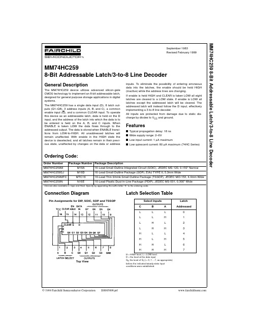
Features
Description
• Buffered Inputs and Outputs
• Four Operating Modes
•
Typical Propagation Delay CL = 15pF, TA = 25oC
of
15ns
at
VCC
=
5V,
• Fanout (Over Temperature Range)
- Standard Outputs . . . . . . . . . . . . . . . 10 LSTTL Loads
The Harris CD74HC259 and CD74HCT259 Addressable Latch features the low-power consumption associated with CMOS circuitry and has speeds comparable to low-power Schottky.
115
Maximum Junction Temperature . . . . . . . . . . . . . . . . . . . . . . . 150oC
Maximum Storage Temperature Range . . . . . . . . . .-65oC to 150oC
2. Wafer or die for this part number is available which meets all electrical specifications. Please contact your local sales office or Harris customer service for ordering information.
SN54LS259中文资料

8-BIT ADDRESSABLE LATCH
LOW POWER SCHOTTKY
• • • • • •
Serial-to-Parallel Conversion Eight Bits of Storage With Output of Each Bit Available Random (Addressable) Data Entry Active High Demultiplexing or Decoding Capability Easily Expandable Common Clear CONNECTION DIAGRAM DIP (TOP VIEW)
• • • • • QN–1 QN–1 L H
H H
H H
QN–1 QN–1
FAST AND LS TTL DATA 5-434
元器件交易网
SN54/74LS259
DC CHARACTERISTICS OVER OPERATING TEMPERATURE RANGE (unless otherwise specified)
N74456D资料
元器件交易网DefinitionsShort-form specification — The data in a short-form specification is extracted from a full data sheet with the same type number and title. For detailed information see the relevant data sheet or data handbook.Limiting values definition — Limiting values given are in accordance with the Absolute Maximum Rating System (IEC 134). Stress above one or more of the limiting values may cause permanent damage to the device. These are stress ratings only and operation of the device at these or at any other conditions above those given in the Characteristics sections of the specification is not implied. Exposure to limiting values for extended periods may affect device reliability.Application information — Applications that are described herein for any of these products are for illustrative purposes only. Philips Semiconductors make no representation or warranty that such applications will be suitable for the specified use without further testing or modification.DisclaimersLife support — These products are not designed for use in life support appliances, devices or systems where malfunction of these products can reasonably be expected to result in personal injury. Philips Semiconductors customers using or selling these products for use in such applications do so at their own risk and agree to fully indemnify Philips Semiconductors for any damages resulting from such application.Right to make changes — Philips Semiconductors reserves the right to make changes, without notice, in the products, including circuits, standard cells, and/or software, described or contained herein in order to improve design and/or performance. Philips Semiconductors assumes no responsibility or liability for the use of any of these products, conveys no license or title under any patent, copyright, or mask work right to these products, and makes no representations or warranties that these products are free from patent, copyright, or mask work right infringement, unless otherwise specified.Philips Semiconductors811 East Arques AvenueP.O. Box 3409Sunnyvale, California 94088–3409Telephone 800-234-7381© Copyright Philips Electronics North America Corporation 1998All rights reserved. Printed in U.S.A.print code Date of release: 10-98。
74HC595芯片资料
74HC595芯片资料8位串行输入/输出或者并行输出移位寄存器,具有高阻关断状态。
三态。
特点8位串行输入8位串行或并行输出存储状态寄存器,三种状态输出寄存器可以直接清除100MHz的移位频率输出能力并行输出,总线驱动串行输出;标准中等规模集成电路应用串行到并行的数据转换Remote control holding register.描述595是告诉的硅结构的CMOS器件,兼容低电压TTL电路,遵守JEDEC标准。
595是具有8位移位寄存器和一个存储器,三态输出功能。
移位寄存器和存储器是分别的时钟。
数据在SCHcp的上升沿输入,在STcp的上升沿进入的存储寄存器中去。
如果两个时钟连在一起,则移位寄存器总是比存储寄存器早一个脉冲。
移位寄存器有一个串行移位输入(Ds),和一个串行输出(Q7’),和一个异步的低电平复位,存储寄存器有一个并行8位的,具备三态的总线输出,当使能OE时(为低电平),存储寄存器的数据输出到总线。
参考数据CPD决定动态的能耗,PD=CPD×VCC×f1+∑(CL×VCC2×f0)F1=输入频率,CL=输出电容f0=输出频率(MHz)Vcc=电源电压功能表H=高电平状态L=低电平状态↑=上升沿↓=下降沿Z=高阻NC=无变化×=无效当MR为高电平,OE为低电平时,数据在SHCP上升沿进入移位寄存器,在STCP上升沿输出到并行端口。
/***************************************************************************************/ 给个74HC595的"慢动作"void WriteSIOByte(unsigned char val){unsigned char i;ACC = val;for (i = 8; i > 0; i --) {SRCLK = 0;//拉低74HC595时钟_rrca_();//右移一位数据SER = CY;//发送74HC595一位串行数据SRCLK = 1;//拉高74HC595时钟_nop_();//延时}SER = 1;//释放数据总线//以下3条指令若在多字节时,应该移入多字节全发送完后在执行此3条指令RCLK = 0;_nop_();//延时RCLK = 1;//打入并行数据}74ls595"速射"hotpowerfor(i = 0; i < buffsize; i ++){SBUF = siobuff[i];while(TI == 0);TI = 0;}RCLK = 0;_nop_();//延时RCLK = 1;//打入并行数据/************************************************************************/摘要:本文介绍了应用移位寄存器芯片74HC595实现LED动、静态显示的基本原理。
74芯片系列功能
功能表74170、74 LS1704×4寄存器阵(OC)读/写寻址分开,可同时进行读和写;存放时间典型值20ns组成4位4字;可扩展到n位1024字;集电极开路输出;74 LS670与本电路相似,只是为三态输出。
写功能表74172多口寄存器阵(三态)独立的读写地址可同时进行读写;每个都采用2位8字结构;三态输出。
74173、74LS173、74HC173、74C1734位D型寄存器(三态)功能表74174、74LS174、74F174、74ALS174、74S174、74HC174、74C174六D型触发器(带清除端)功能表74175、74LS175、74F175、74ALS175、74S175、74HC175、74C175 四D型触发器(带清除端)功能表74176可预置十进制计数器功能表十进制(BCD)二—五混合进制74178、741794位并行存取移位寄存器178、179功能表74180、74 HC1809位奇偶数发生器/校验器功能表74181、74LS181、74S181、74F181、74 HC181算术逻辑单元/功能发生器能实现两个4位字的16种二进制算术运算及16种逻辑运算(见表a和表b);当与74182、74S182或74HC182超前进位电路共同使用时,可完成高速算术运算;若该电路引脚名称如引脚表所示,则可兼容有效高或有效低数据;该电路也可用作比较器,A=B输出是集电极开路。
功能表引脚表74182、74 S182、74F182、74 HC182超前进位发生器74 H183、74LS183、74 HC183双进位保存全加器功能表(每个加法器)74184BCD二进制转换器BCD—二进制转换器; 可编程产生BCD9的补码或BCD10的补码。
BCD二进制转换器功能表BCD9或10的补码转换器功能表74185A二进制—BCD转换器引脚图与74184相同。
功能表74190、74LS190、74F190、74 A LS190、74 HC190可预置BCD十进制同步可逆计数器(带方式控制)功能表74191、74LS191、74F191、74 A LS191、74 HC191可预置二进制同步可逆计数器(带方式控制)引脚图与74190相同。
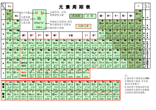
化学元素周期表 中文+拼音(高清)
26.98 28.09 30.97 32.07 35.45 39.95 K 2
19 K 20 Ca 21 Sc 22 Ti 23 V 24 Cr 25 Mn 26 Fe 27 Co 28 Ni 29 Cu 30 Zn 31 Ga 32 Ge 33 As 34 Se 35 Br 36 Kr
4 钾jiǎ 钙gài 钪kà 钛tài 钒fán 铬gè
氙xiā
N M
5s25p4 5s25p5 5s25p6 L
18 18 8
85.47 87.62 88.91 91.22 92.91 95.94 [99] 101.1 102.9 106.4 107.9 112.4 114.8 118.7 121.8 127.6 126.9 131.3 K 2
55 Cs 56 Ba 57-71 72 Hf 73 Ta 74 W 75 Re 76 Os 77 Ir 78 Pt 79 Au 80 Hg 81 Tl 82 Pb 83 Bi 84 Po 85 At 86 Rn P 8
锰mě
铁tiě
钴gǔ
镍niè
铜tó
锌xīn 镓jiā 锗zhě 砷shě
硒xī 溴xiù
氪kè
N8 M 18
4s1
4s2 3d14s2 3d24s2 3d34s2 3d54s1 3d54s2 3d64s2 3d74s2 3d84s2 3d104s1 3d104s2 4s24p1 4s24p2 4s24p3 4s24p4 4s24p5 4s24p6 L 8
5
铷rú
5s1
锶sī
5s2
钇yǐ 锆gào
4d15s2 4d25s2
铌ní
4d 5s1
钼mù
4d55s1
ICN2595_datasheet_CN_2015_V0.2

(16路恒流输出LED驱动芯片)(替代2颗74HC595)概述ICN2595是一款专为单双色LED 显示模块和显示器设计的驱动IC,具有16路恒定的电流输出驱动能力。
一颗ICN2595=2颗74HC595ICN2595采用了“Noise Free TM”技术,具有极佳的抗干扰特性,恒流及低灰效果不受PCB 板的影响。
并可选用不同的外接电阻对输出级电流大小进行任意调节,精确控制LED 的发光亮度。
ICN2595内部设计了16位移位寄存器和锁存器, 可以将串行输入数据转化为并行输出数据格式,通过外部使能信号控制LED 的关断。
同时内部采用了电流精确控制技术,可使片间误差低于±2.5%,通道间误差低于±1.5%。
特性✧ 16路等电流输出通道 ✧ 一颗ICN2595=2颗74HC595 ✧ 输出电流设定范围:0.5~65mA×16@V DD =5V 路恒定电流输出 0.5~35mA×16@V DD =3.3V 路恒定电流输出 ✧ 电流精度通道间的电流精度:±0.7%(一般值)±1.3%(最大值)芯片间的电流精度:±1%(一般值)±2.5%(最大值)✧ 快速输出电流响应(最小值):40ns@V DD =5V ✧ I/O 施密特触发器触发输入 ✧ 数据传输频率:f MAX =35MHz(最大) ✧ ESD HBM PASS 8KV ✧ 供电电压:V DD =3.3~6V ✧ 工作温度范围:T opr =-40~85℃ ✧ 具有极佳的抗干扰能力和低灰度效果ICN2595引脚说明ICN2595框图I/O 等效电路1. CLK, SIN2. OE3. LE4.SOUTDD时序图Note 1:当LE 引脚设定为L,锁存电路保持数据;当LE 引脚设定为H,则锁存电路不保持数据,数据直接输出。
当OE 引脚为L 时, OUT0到OUT15输出引脚将变为ON 和OFF 以响应数据;设定OE 引脚为H,不论数据如何,所有输出引脚将为OFF。
SN74HC259PW中文资料

元器件交易网IMPORTANT NOTICETexas Instruments and its subsidiaries (TI) reserve the right to make changes to their products or to discontinueany product or service without notice, and advise customers to obtain the latest version of relevant informationto verify, before placing orders, that information being relied on is current and complete. All products are soldsubject to the terms and conditions of sale supplied at the time of order acknowledgement, including thosepertaining to warranty, patent infringement, and limitation of liability.TI warrants performance of its semiconductor products to the specifications applicable at the time of sale inaccordance with TI’s standard warranty. Testing and other quality control techniques are utilized to the extentTI deems necessary to support this warranty. Specific testing of all parameters of each device is not necessarilyperformed, except those mandated by government requirements.CERTAIN APPLICATIONS USING SEMICONDUCTOR PRODUCTS MAY INVOLVE POTENTIAL RISKS OFDEATH, PERSONAL INJURY, OR SEVERE PROPERTY OR ENVIRONMENTAL DAMAGE (“CRITICALAPPLICATIONS”). TI SEMICONDUCTOR PRODUCTS ARE NOT DESIGNED, AUTHORIZED, ORWARRANTED TO BE SUITABLE FOR USE IN LIFE-SUPPORT DEVICES OR SYSTEMS OR OTHERCRITICAL APPLICATIONS. INCLUSION OF TI PRODUCTS IN SUCH APPLICATIONS IS UNDERSTOOD TOBE FULLY AT THE CUSTOMER’S RISK.In order to minimize risks associated with the customer’s applications, adequate design and operatingsafeguards must be provided by the customer to minimize inherent or procedural hazards.TI assumes no liability for applications assistance or customer product design. TI does not warrant or representthat any license, either express or implied, is granted under any patent right, copyright, mask work right, or otherintellectual property right of TI covering or relating to any combination, machine, or process in which suchsemiconductor products or services might be or are used. TI’s publication of information regarding any thirdparty’s products or services does not constitute TI’s approval, warranty or endorsement thereof.Copyright © 1998, Texas Instruments Incorporated。
lm2594芯片使用说明(lm2594中文资料)

lm2594芯⽚使⽤说明(lm2594中⽂资料)[导读] lm2594芯⽚使⽤说明(lm2594中⽂资料) LM2594提供所有活动功能的单⽚集成电路降压(巴克)开关式稳压器,能够驾驶0.5负载线和负载调节的。
这些器件可在3.3V、5V、12Vlm2594芯⽚使⽤说明(lm2594中⽂资料)LM2594提供所有活动功能的单⽚集成电路降压(巴克)开关式稳压器,能够驾驶0.5负载线和负载调节的。
这些器件可在3.3V、5V、12V的固定输出电压和可调输出版本中使⽤,并且封装在⼀个8导通DIP和⼀个8导通表⾯安装包中。
这些调节器需要最少数量的外部元件,使⽤简单,具有内部频率补偿、固定频率振荡器和改进的线路和负载调节规范。
LM2594以150kHz的开关频率运⾏,因此⽐低频率开关调节器所需的更⼩的滤波器组件。
由于它的⾼效率,印刷电路板上的铜-per痕迹通常是唯⼀需要的散热。
⼀个标准系列的电感(包括通孔和表⾯安装类型)可从⼏个不同的⼿动-facturers优化使⽤与LM2594。
该特性⼤⼤简化了开关电源的设计。
其他的特性还包括保证±4%的公差在所有条件下输出电压输⼊电压和输出负载条件下,振荡频率和±15%。
包括Ex-ternal关闭,通常是85µa待机电流。
⾃保护特性包括输出开关的两级减少电流限制和故障条件下完全保护的过温关机。
最⼤供电电压:LM259445 VLM2594HV 60V开/关引脚输⼊电压0.3±V±25V反馈引脚电压0.3±V±25V输出电压对地(稳态)-1V内部功耗限制储存温度范围为65℃~150℃静电放电敏感性⼈体模型(注释2)2千伏铅温度M8封装⽓相(60秒)+ 215℃红外(15秒)+ 220℃N封装(焊接,10秒)+ 260℃最⼤结温+150℃操作条件温度范围为40℃C=TJ+125℃注意事项:注1:绝对最⼤额定值表明超过该设备损坏可能发⽣的限制。
74ls259逻辑表达式 -回复
74ls259逻辑表达式-回复74LS259是一种8位地址锁存器芯片,常用于数字逻辑电路和存储器控制电路。
在本篇文章中,我们将深入探讨74LS259的逻辑表达式以及其在电路设计中的应用。
首先,我们需要了解逻辑表达式的概念。
逻辑表达式是通过逻辑运算符(如与、或、非)将多个逻辑变量进行组合,并用布尔代数的形式表示的数学表达式。
逻辑表达式用于描述数字电路的行为和功能。
对于74LS259来说,它具有8个输入引脚(D0-D7)和8个输出引脚(Q0-Q7)。
此外,它还有三个控制引脚(G, MR, CE),分别用于使能(控制数据输入)、复位和时序控制。
那么,74LS259的逻辑表达式是什么呢?我们可以通过分析其功能和应用场景来确定其逻辑表达式。
74LS259是一个数据锁存器,用于将输入数据存储在内部存储器中,并在时钟脉冲到来时将存储的值传送到输出引脚。
它有两种工作模式:“存储模式”和“传输模式”。
在存储模式下,当G引脚为低电平(使能)时,输入数据将被存储在内部存储器中,此时数据锁存器处于保持状态。
当G引脚为高电平(禁止)时,输入数据不会被存储,并且数据锁存器处于保持状态。
在传输模式下,当G引脚为低电平(使能)时,存储的数据将从内部存储器传输到输出引脚,此时数据锁存器处于透明状态,输入数据可以通过输出引脚读取。
当G引脚为高电平(禁止)时,数据锁存器处于保持状态,不会有数据传输。
根据上述功能描述,我们可以得出74LS259的逻辑表达式如下:存储模式:Q0= D0*G + Q0*G',Q1= D1*G + Q1*G', ... ,Q7= D7*G + Q7*G'传输模式:Q0= D0*G', Q1= D1*G', ... Q7= D7*G'其中,G'表示G引脚的反相值。
通过上述逻辑表达式,我们可以进行电路设计,并将74LS259芯片应用于各种数字逻辑和存储器控制电路中。
74系列芯片功能大全
74157 TTL 74158 TTL74 系列芯片功能大全7400 TTL 2 输入端四与非门7401 TTL 集电极开路 2 输入端四与非门 7402 TTL 2 输入端四或非门7403 TTL74132 TTL 2 输入端四与非施密特触发器 74133 TTL 13 输入端与非门 74136 TTL 四异或门 74138 TTL 3-8 线译码器 /复工器 74139 TTL 双 2-4 线译码器 / 复工器 7414 TTL 六反相施密特触发器 74145 TTL BCD —十进制译码 /驱动器 7415 TTL 开路输出 3 输入端三与门 74150 TTL 16 选 1 数据选择 / 多路开关74151 TTL 8 选 1 数据选择器 74153 TTL 双 4 选 1 数据选择器74154 TTL 4 线— 16 线译码器 图腾柱输出译码器 /分配器 开路输出译码器 /分配器可预置 BCD 同步清除计数器 可予制四位二进制同步清除计数器7416 TTL 74160 TTL 74161 TTL 同相输出四 2 选 1 数据选择器反相输出四 2 选 1 数据选择器 开路输出六反相缓冲 / 驱动器 可预置 BCD 异步清除计数器 可予制四位二进制异步清除计数器7404 TTL 7405 TTL 7406 TTL 7407 TTL 六反相器 集电极开路六反相器 集电极开路六反相高压驱动器 集电极开路六正相高压驱动器 7408 TTL 2 输入端四与门7409 TTL 集电极开路 2 输入端四与门 7410 TTL 3 74107 TTL 74109 TTL 7411 TTL 3 输入端 3 与非门带清除主从双 J-K 触发器 带预置清除正触发双 J-K 触发器 输入端3 与门74112 TTL 带预置清除负触发双 J-K 触发器 7412 TTL 开路输出 3 输入端三与非门 单稳态多谐振荡器 可再触发单稳态多谐振荡器 双可再触发单稳态多谐振荡器 三态输出高有效四总线缓冲门 三态输出低有效四总线缓冲门 输入端双与非施密特触发器 74121 TTL 74122 TTL 74123 TTL 74125 TTL 74126 TTL 7413 TTL 4 集电极开路2 输入端四与非门 74155 TTL 74156 TTL 74162 TTL 74163 TTL74259 TTL 7426 TTL 2八位可寻址锁存器 /3-8 线译码器 输入端高压接口四与非门 74260 TTL 5 输入端双或非门 74266 TTL 2 输入端四异或非门7427 TTL 3 输入端三或非门 74273 TTL 带公共时钟复位八 D 触发器74279 TTL 四图腾柱输出 S-R 锁存器74164 TTL 74165 TTL 74166 TTL 八位串行入 /并行输出移位寄存器 八位并行入 /串行输出移位寄存器 八位并入 /串出移位寄存器 74169 TTL 7417 TTL二进制四位加 /减同步计数器 开路输出六同相缓冲 /驱动器74170 TTL 74173 TTL 74174 TTL 74175 TTL 开路输岀4X 4寄存器堆 三态输出四位 D 型寄存器 带公共时钟和复位六 D 触发器 带公共时钟和复位四 D 触发器74180 TTL 9 位奇数 /偶数发生器 /校验器 74181 TTL 算术逻辑单元 /函数发生器 74185 TTL 二进制— BCD 代码转换器 74190 TTL BCD 同步加 / 减计数器74191 TTL 74192 TTL 二进制同步可逆计数器 可预置 BCD 双时钟可逆计数器 74193 TTL 74194 TTL 74195 TTL 74196 TTL 74197 TTL 可预置四位二进制双时钟可逆计数器 四位双向通用移位寄存器 四位并行通道移位寄存器 十进制 /二 -十进制可预置计数锁存器 二进制可预置锁存器 /计数器 7420 TTL 4 7421 TTL 4 7422 TTL 74221 TTL 74240 TTL 输入端双与非门 输入端双与门开路输出 4 输入端双与非门 双/单稳态多谐振荡器 八反相三态缓冲器 /线驱动器74241 TTL 74243 TTL 74244 TTL 74245 TTL八同相三态缓冲器 /线驱动器 四同相三态总线收发器 八同相三态缓冲器 /线驱动器 八同相三态总线收发器 74247 TTL BCD —7 段 15V 输岀译码 /驱动器 74248 TTL BCD —7 段译码 /升压输岀驱动器 74249 TTL BCD —7 段译码 /开路输岀驱动器 三态输岀 8 选 1 数据选择器 /复工器 74251 TTL 74253 TTL 74256 TTL 74257 TTL 74258 TTL 三态输出双 4 选 1 数据选择器 双四位可寻址锁存器 三态原码四 2选 1 数据选择器 三态反码四 2选 1 数据选择器/复工器 /复工器 /复工器7428 TTL 2 输入端四或非门缓冲器 74283 TTL 4 位二进制全加器7440 TTL 4 输入端双与非缓冲器 74366 TTL 74367 TTL4/2 线使能输入三态六同相线驱动器 74368 TTL 4/2 线使能输入三态六反相线驱动器 7437 TTL 开路输出 2 输入端四与非缓冲器 74373 TTL 三态同相八 D 锁存器 74374 TTL 三态反相八 D 锁存器 74375 TTL 4 位双稳态锁存器74290 TTL 二/五分频十进制计数器 74293 TTL 74295 TTL 二/八分频四位二进制计数器 四位双向通用移位寄存器 74298 TTL 74299 TTL 7430 TTL 8 7432 TTL 2 74322 TTL四 2 输入多路带存贮开关 三态输出八位通用移位寄存器 输入端与非门 输入端四或门 带符号扩展端八位移位寄存器 三态输出八位双向移位 /存贮寄存器 74323 TTL 7433 TTL 开路输出 2 输入端四或非缓冲器 74347 TTL BCD —7 段译码器 /驱动器74352 TTL 74353 TTL 双 4 选 1 数据选择器 / 复工器 三态输出双 4 选 1 数据选择器 /复工器 门使能输入三态输出六同相线驱动器 门使能输入三态输出六同相线驱动器 门使能输入三态输出六反相线驱动器 74367 TTL 4/2 线使能输入三态六同相线驱动器 74368 TTL 4/2 线使能输入三态六反相线驱动器74365 TTL74365 TTL74366 TTL7437 TTL 开路输出 2 输入端四与非缓冲器 74373 TTL 三态同相八 D 锁存器 74374 TTL 三态反相八 D 锁存器74375 TTL 4 位双稳态锁存器 74377 TTL74378 TTL 74379 TTL7438 TTL 74380 TTL 7439 TTL 74390 TTL 74393 TTL 单边输出公共使能八单边输出公共使能六 双边输出公共使能四 开路输出 2 输入端四与非缓冲器多功能八进制寄存器开路输出 2 输入端四与非缓冲器 双十进制计数器 双四位二进制计数器D 锁存器D 锁存器D 锁存器7442 TTL BCD —十进制代码转换器双 4 选 1 数据选择器 / 复工器 三态输出双 4 选 1 数据选择器 /复工器 门使能输入三态输出六同相线驱动器 74352 TTL 74353 TTL 74365 TTL 门使能输入三态输出六反相线驱动器74564 TTL 74573 TTL7442 TTL BCD —十进制代码转换器 74447 TTL BCD —7 段译码器 /驱动器 7445 TTL BCD —十进制代码转换 /驱动器74450 TTL 16:1 多路转接复用器多工器 74451 TTL 双 8:1 多路转接复用器多工器74453 TTL 四 4:1 多路转接复用器多工器 74490 TTL 双十进制计数器 74491 TTL 十位计数器 74498 TTL 八进制移位寄存器 7450 TTL 2-3/2-2 输入端双与或非门 74502 TTL 八位逐次逼近寄存器 74503 TTL 八位逐次逼近寄存器 7451 TTL 2-3/2-2 输入端双与或非门 74533 TTL 三态反相八 D 锁存器74534 TTL 三态反相八 D 锁存器 7454 TTL 四路输入与或非门74540 TTL 7455 TTL 4 74563 TTL 八位三态反相输出总线缓冲器 输入端二路输入与或非门 八位三态反相输出触发器74574 TTL 74645 TTL 74670 TTL 7473 TTL 7474 TTL74377 TTL 74378 TTL 74379 TTL 单边输出公共使能八 单边输出公共使能六 双边输出公共使能四 D 锁存器 D 锁存器 D 锁存器7438 TTL 74380 TTL 开路输出 2 输入端四与非缓冲器多功能八进制寄存器开路输岀 2 输入端四与非缓冲器 双十进制计数器 双四位二进制计数器 7440 TTL 4 输入端双与非缓冲器 7439 TTL 74390 TTL74393 TTL7446 TTL BCD —7 段低有效译码 /驱动器 十位比较器 八进制计数器 三态同相 三态反相 74460 TTL 74461 TTL 74465 TTL 74466 TTL2 与使能端八总线缓冲器 2 与使能八总线缓冲器三态同相 三态反相 八位双向计数器 7447 TTL BCD —7 段高有效译码 /驱动器 7448 TTL BCD —7 段译码器 /内部上拉输岀驱动 74467 TTL 74468 TTL 74469 TTL 2 使能端八总线缓冲器 2 使能端八总线缓冲器74564 TTL 74573 TTL八位三态反相输出 D 触发器八位三态输出触发器八位三态输出D 触发器三态输出八同相总线传送接收器三态输岀4X4寄存器堆带清除负触发双 J-K 触发器带置位复位正触发双 D 触发器323340 7476 TTL 带预置清除双 J-K 触发器 7483 TTL 四位二进制快速进位全加器 7485 TTL 四位数字比较器 7486 TTL 2 输入端四异或门7490 TTL 可二 /五分频十进制计数器 7493 TTL 可二 /八分频二进制计数器 7495 TTL 四位并行输入 输出移位寄存器 7497 TTL 6 位同步二进制乘法器常用 74 系列标准数字电路的中文名称资料 器件代号 器件名称 74 74LS 74HC42 4 线-10 线译码器 (BCD 43 4 线-10线译码器 (余 3码输入 ) V00 01 四 2 输入端与非门四 2 输入端与非门 02 03 四 2 输入端或非门 四 2 输入端与非门 04 (OC) V VVVV(OC) V V V05 06 07 08 六反相器 V V 六反相器 (OC) V V 六高压输出反相器 (OC,30V) V V 六高压输出缓冲2 输入端与门 ,驱动器 (OC,30V) V V VVVV09 10 112 输入端与门3 输入端与非门 3 输入端与门(OC) V V VVVVVV 12 133 输入端与非门 双4 输入端与非门(OC) V V V VVV14 15 16 17 20 21 22 25六反相器 V V 三 3 输入端与门 六高压输出反相器 六高压输出缓冲 ,驱动器 (OC,15V) 双 4 输入端与非门 双 4 输入端与门 双 4 输入端与非门 双 4 输入端或非门 (OC) V V (OC,15V) V VVV 26 VVV(OC) V V (有选通端 ) V四 2 输入端高压输出与非缓冲器 VVVVV三 3 输入端或非门 V V V四 2 输入端或非缓冲器 V V V 30 8 输入端与非门 V V V27 28 37 2 输入端或门 V V V 2 输入端或非缓冲器 2 输入端与非缓冲器 (OC) V V VV 38 2 输入端与非缓冲器 双 4 输入端与非缓冲器(OC) V VVVV输入 ) V V126 128 13244 4线-10线译码器 (余 3葛莱码输入 ) V 48 4 线-7段译码器 V49 4 线-7段译码器 V 50 双 2 路 2-2 输入与或非门 51 2 52 4 53 4 54 4 VVV 路 3-3 输入 ,2 路 2-2 输入与或非门 V V V 路 2-3-2-2 输入与或门 V 路 2-2-2-2 输入与或非门 路 2-3-3-2 输入与或非门 路 4-4 输入与或非门 V V VV 55 2 60 双 4 输入与扩展器 V V 61 三 3 输入与扩展器 V 62 4 路 2-3-3-2 输入与或扩展器 64 4 路 4-2-3-2 输入与或非门 65 4 路 4-2-3-2 输入与或非门 (OC) V 70 71 72 74 78 85 与门输入 J-K 触发器 V 与或门输入 J-K 触发器 V 与门输入 J-K 触发器 V 双上升沿 D 型触发器 V V 双 D 型触发器 V V 四位数值比较器 V 四 2 输入端异或门 V V V 86 87 4 位二进制原码 /反码 V 95 4 位移位寄存器 V 与或门输入 J-K 触发器 V 与门输入 J-K 触发器 V 双主 -从 J-K 触发器 双主-从J-K 触发器 双主 -从 J-K 触发器101 102 107 108 109 110 111 112 113 114 与门输入 J-K 触发器 V 双主 -从 J-K 触发器 V V 双下降沿 双下降沿 双下降沿J-K 触发器 J-K 触发器 J-K 触发器116 120 121 122 123 125 双 4 位锁存器 V 双脉冲同步驱动器 V 单稳态触发器 V V 可重触发单稳态触发器 可重触发双稳态触发器 四总线缓冲器 V V 四总线缓冲器 V VVVVV V四2 输入端或非线驱动器 V V V 四2输入端与非门 V V VSN74HC4078 3输入端三或门4000 CD4043 四或非R/S锁存器CD4044 四与非R/S锁存器CD4046 锁相环CD4047 单非稳态多谐振荡器CD4048 可扩充八输入门CD4049 六反相缓冲/转换器CD4050 六正相缓冲/转换器CD4051 单8通道多路转换/分配CD4052 双4通道多路转换/分配CD4053 三2通道多路转换/分配CD4056 7段液晶显示译码/驱动CD4060 二进制计数/分频/振荡CD4063 四位数值比较器CD4066 四双相模拟开管CD406716选1模拟开关CD4068 8输入端与非/与门CD4069 六反相器CD4070 四异或门CD4071 四2输入或门CD4072 双四输入或门CD4073 三3输入与门CD4075 三3输入与门CD4076 4位D型寄存器CD4077 四异或非门CD4078 八输入或/或非门CD4081 四输入与门CD4082 双4输入与门CD4085 双2组2输入与或非门CD4086 可扩展2输入与或非门CD4093 四与非斯密特触发器CD4094 8位移位/贮存总线寄存CD4096 3输入J-K触发器CD4098 双单稳态触发器CD4099 8位可寻址锁存器CD40103 同步可预置减法器CD40106 六斯密特触发器四时钟D型锁存器CD40424500双2输入与非缓冲/驱动SN74HC4511 7段锁存/译码驱动器CD4502 可选通六反相缓冲器CD4503 六同相缓冲器CD4504 六电平转换器CD4508 双4位锁存器CD4510 BCD可预置可逆计数器CD4511CD4512BCD7段锁存/译码/驱动4 - 16线译码器4 - 16线译码器双BCD加法计数器双二进制加法计数器24位分频器可预置BCD1/N计数可预置二进制 1/N计数BCD系数乘发器双单稳态触发器12位奇偶校验电路8位优先编码器双精密单稳态触发器双四路输据选择器可编程振荡/计时器7段锁存/译码/驱动3位BCD计数器双4选1译码器双4选1译码器1-64位可变长度寄存器CD4558CD4560CD4561CD4566CD4569CD4583BCD7段锁存/译码/驱动8通道数据选择器BCD-7段译码器BCD码加法器BCD转换成9的补码输岀工业定时基准发生器双4位可编程 1/NBCD双斯密特触发器4斯密特触发器CD40110。
sn74hc595中文版
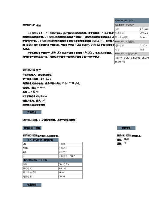
SN74HC595 概述74HC595包含一个8位串行输入,并行输出的移位寄存器,该寄存器向一个8位D型存储寄存器提供数据。
74HC595的存储寄存器具备三态输出。
移位寄存器和存储寄存器分别有独立的时钟。
74HC595的移位寄存器带有最高优先级的直接清零端(SRCLR)、串行输入端(SER)和用于级联的串行输出端。
当输出使能端(OE)为高时,74HC595的输出将处于高阻态。
不管是移位寄存器时钟(SRCLK)还是存储寄存器时钟(RCLK),都是上升沿触发。
如果两个时钟绑定在一起,则移位寄存器将一直领先存储寄存器一个时钟脉冲。
SN74HC595 参数74HC595 主要参数电压 2.0~6.0 驱动电流-6/6 mA 最大传输延迟34 ns 74HC595 其他特性逻辑电平CMOS 清零异步74HC595 封装与引脚PDIP16, SOIC16, SOP16, SSOP1 TSSOP16SN74HC595 特性8位串行输入,并行输出移位宽工作电压范围:2.0~6.0 V高强度电流三态输出,最多可驱动高达15个LSTTL负载低功耗,最大I CC80μA典型t pd = 13 ns5 V下驱动电流为±6 mA低输入电流,最大1μA移位寄存器可直接清零产品简介SN74HC595N,8 位移位寄存器,具有三态输出锁存型号标识/ 参数SN74HC595N型号标识及主要参数:封装类型SN74HC595N封装信息:类型:PDIP引脚:16包装规格SN74HC595N包装规格:类型:Tube(管装)每管:25 pcs产品简介SN74HC595D,8 位移位寄存器,具有三态输出锁存型号标识/ 参数SN74HC595D型号标识及主要参数:。
F6N0.25BK100,F6N0.75BK50,F6N0.38BK75,F6N1.25BK25,F6N0.50BK75,F6N1.50BK25, 规格书,Datasheet 资料
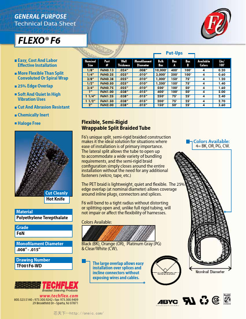
FLEXO® F6Flexible, Semi-RigidWrappable Split Braided TubeF6’s unique split, semi-rigid braided constructionmakes it the ideal solution for situations whereease of installation is of primary importance.The lateral split allows the tube to open upto accommodate a wide variety of bundlingrequirements, and the semi-rigid braidconfiguration simply closes around the entireinstallation without the need for any additionalfasteners (velcro, tape, etc.)edge overlap (at nominal diameter) allows coveragearound inline plugs, connectors and splices.F6 will bend to a tight radius without distortingor splitting open and, unlike full rigid tubing, willnot impair or affect the flexibility of harnesses.Colors Available:Black (BK), Orange (OR), Platinum Gray (PG)& Clear/White (CW).E asy, Cost And LaborEffective InstallationM ore Flexible Than SplitConvoluted Or Spiral Wrap25% Edge OverlapS oft And Quiet In HighVibration UsesC ut And Abrasion ResistantC hemically InertH aloge FreePolyethylene TerepthalateMaterialF6NGrade.008” - .015”Monofilament DiameterTF001F6-WDDrawing NumberHot KnifeCut Cleanly800.323.5140 • 973.300.9242 • fax: 973.300.940929 Brookfield Dr • Sparta, NJ 07871Braided Sleeving ProductsColors Available:4= BK, OR, PG, CW.Nominal DiameterThe large overlap allows easyinstallation over splices andincline connectors withoutexposing wires and cables.NominalSizePart#WallThicknessMonofilamentDiameterBulkBoxBoxABoxBAvailableColorsLbs/100’1/8”F6N0.13.024”.008”10,000’400’100’40.201/4”F6N0.25.025”.010”3,000’200’100’40.603/8”F6N0.38.025”.010”1,000’150’75’4 1.201/2”F6N0.50.025”.010”1,200’150’75’4 1.403/4”F6N0.75.025”.010”500’100’50’4 1.601”F6N1.00.038”.015”400’100’50’4 2.001 1/4”F6N1.25.038”.015”250’75’25’4 2.401 1/2”F6N1.50.038”.015”200’75’25’4 2.702”F6N2.00.038”.015”150’50’25’4 3.60Put-Ups芯天下--/FLEXO® F6Abrasion ResistanceMediumAbrasion Test MachineTaber 5150Abrasion Test WheelCalibrase H-18Abrasion Test Load 500gRoom Temperature 80°FHumidity74%Some Scuffing Visible500 Test CyclesSignificant Wear Is Visible With Several Braid Filaments Broken1,200 Test CyclesMaterial Destroyed 1,950 Test CyclesPre-Test Weight5,365.1 mgPost-Test Weight 4,850 mgTest End Loss Of Mass Point Of Destruction515.1 mg1=No Effect 4=More Affected 2=Little Effect 5=Severely Affected 3=AffectedAromatic Solvents ______________2Aliphatic Solvents ______________1Chlorinated Solvents ____________3Weak Bases __________________1Salts _________________________1Strong Bases___________________2Salt Water 0-S-1926 ____________1Hydraulic Fluid MIL-H-5606 _______1Lube Oil MIL-L-7808 ____________1De-Icing Fluid MIL-A-8243 ________1Strong Acids __________________3Strong Oxidants ________________2Esters/Keytones _______________1UV Light ______________________1Petroleum ____________________1Fungus ASTM G-21 _____________1Halogen Free ________________Yes RoHS ______________________Yes SVHC _____________________NoneRating ___________UL94VOMonofilament Diameter__.008-.015 ASTM D-204Flammability Rating________UL94Recommended Cutting___Hot Knife Colors______________________4 Wall Thickness_________.024-.038Tensile Strength (Yarn)_______6-10ASTM D-2256 LbsSpecific Gravity ASTM D-792__1.38Moisture Absorption_________.1-.2 % ASTM D-570Hard Vacuum Data ASTM E-595TML_______________________19CVCM_____________________.00WVR______________________.16Smoke D-Max _______________56 ASTM E-662Outgassing________________Med Oxygen Index________________21ASTM D-2863© 2011 Techflex, Inc. - Any unauthorized reproduction, in whole or part, in any medium whatsoever, without the express written permission of Techflex, Inc. is strictly forbidden.T echflex product names and logos are registered trademarks of T echflex, Inc., unless otherwise attributed. The contents and illustrations contained herein are believed to be reliable. T echflex makes no warranties as to their accuracy or completeness and disclaims any liability in connection with their use. T echflex’s only obligations are those in standard terms ofsale for these products and T echflex will not be liable for any consequential or other damages arising due to misuse of these products or typographical errors or omissions.Users should make their own evaluation to determine the suitability of these products for their unique and specific applications.09-11Melt Point ASTM D-2117482°F (250°C)Maximum ContinuousMil-I-23053257°F (125°C)Minimum Continuous-94°F (-70°C)芯天下--/。
集成电路大全

SN74LS259
8位可寻址锁存器
SN74LS275
七位树型乘法器
SN74LS261
2x4位二进制乘发器
SN74LS279
四R-S触发器
SN74LS273
八进制D型触发器
SN74LS283
4位二进制全加器
SN74LS276
四J-K触发器
SN74LS293
4位二进制计数器
SN74LS280
四3态总线缓冲器
SN74LS133
13输入与非门
SN74LS132
二输入与非触发器
SN74LS137
地址锁存3-8线译码器
SN74LS136
四异或门
SN74LS139
双2-4线译码-转换器
SN74LS138
3-8线译码/转换器
SN74LS147
10-4线优先编码器
SN74LS145
BCD十进制译码/驱动器
双J-K负沿触发器
SN74LS112
双J-K负沿触发器
SN74LS121
单稳态多谐振荡器
SN74LS114
双J-K负沿触发器
SN74LS123
双稳态多谐振荡器
SN74LS122
单稳态多谐振荡器
SN74LS125
三态缓冲器
SN74LS124
双压控振荡器
SN74LS131
3-8线译码器
SN74LS126
四输入端与非缓冲器
SN74LS38
双2输入与非缓冲器
SN74LS40
四输入端与非缓冲器
SN74LS42
BCD-十进制译码器
SN74LS47
BCD-七段译码驱动器
SN74LS48
MM74HC259中文资料
MM74HC259N
N16E
16-Lead Plastic Dual-In-Line Package (PDIP), JEDEC MS-001, 0.300” Wide
Devices also available in Tape and Reel. Specify by appending the suffix letter “X” to the ordering code.
Output Voltage
|IOUT| ≤ 20 µA
4.5V
4.2
3.98
3.84
6.0V
5.7
5.48
5.34
2.0V
0
0.1
0.1
4.5V
0
0.1
0.1
3.7
V
5.2
V
0.1
V
0.1
V
6.0V
0
0.1
0.1
0.1
V
VIN = VIH or VIL
|IOUT| ≤ 4.0 mA
4.5V
0.2
0.26
Logic Diagram
2
MM74HC259
元器件交易网
Absolute Maximum Ratings(Note 1)
(Note 2)
Recommended Operating Conditions
Supply Voltage (VCC) DC Input Voltage (VIN) DC Output Voltage (VOUT) Clamp Diode Current (IIK, IOK) DC Output Current, per pin (IOUT) DC VCC or GND Current, per pin (ICC) Storage Temperature Range (TSTG) Power Dissipation (PD)
N74F27D资料
元器件交易网DIP14:plastic dual in-line package; 14 leads (300 mil)SOT27-1SO14:plastic small outline package; 14 leads; body width 3.9 mm SOT108-1DefinitionsShort-form specification — The data in a short-form specification is extracted from a full data sheet with the same type number and title. For detailed information see the relevant data sheet or data handbook.Limiting values definition — Limiting values given are in accordance with the Absolute Maximum Rating System (IEC 134). Stress above one or more of the limiting values may cause permanent damage to the device. These are stress ratings only and operation of the device at these or at any other conditions above those given in the Characteristics sections of the specification is not implied. Exposure to limiting values for extended periods may affect device reliability.Application information — Applications that are described herein for any of these products are for illustrative purposes only. Philips Semiconductors make no representation or warranty that such applications will be suitable for the specified use without further testing or modification.DisclaimersLife support — These products are not designed for use in life support appliances, devices or systems where malfunction of these products can reasonably be expected to result in personal injury. Philips Semiconductors customers using or selling these products for use in such applications do so at their own risk and agree to fully indemnify Philips Semiconductors for any damages resulting from such application.Right to make changes — Philips Semiconductors reserves the right to make changes, without notice, in the products, including circuits, standard cells, and/or software, described or contained herein in order to improve design and/or performance. Philips Semiconductors assumes no responsibility or liability for the use of any of these products, conveys no license or title under any patent, copyright, or mask work right to these products, and makes no representations or warranties that these products are free from patent, copyright, or mask work right infringement, unless otherwise specified.Philips Semiconductors811 East Arques AvenueP.O. Box 3409Sunnyvale, California 94088–3409Telephone 800-234-7381© Copyright Philips Electronics North America Corporation 1998All rights reserved. Printed in U.S.A.print code Date of release: 10-98。
74AC259资料

MC74AC259, MC74ACT2598−Bit Addressable LatchThe MC74AC259/74ACT259 is a high−speed 8−bit addressable latch designed for general purpose storage applications in digital systems. It is a multifunctional device capable of storing single line data in eight addressable latches, and also a 1−of−8 decoder and demultiplexer with active HIGH outputs. The device also incorporates an active LOW Common Clear for resetting all latches, as well as an active LOW Enable. It is functionally identical to the ALS259 8−bit addressable latch.•Serial−to−Parallel Conversion•Eight Bits of Storage with Output of Each Bit Available •Random (Addressable) Data Entry•Active High Demultiplexing or Decoding Capability •Easily Expandable •Common Clear•Pb−Free Packages are Available151614131211102134567V CC 98MR E D Q 7Q 6Q 5Q 4A 0A 1A 2Q 0Q 1Q 2Q 3GNDFigure 1. Pinout: 16−Lead Packages Conductors(Top View)Figure 2. Logic SymbolMODE SELECT TABLEE MR ModeL H Addressable Latch H H MemoryL L Active HIGH 8−Channel Demultiplexer HLClearH = HIGH Voltage Level L = LOW Voltage LevelORDERING INFORMATIONSee detailed ordering and shipping information in the package dimensions section on page 9 of this data sheet.MODE SELECT−FUNCTION TABLEOperating ModeInputs OutputsMR E D A0A1A2Q0Q1Q2Q3Q4Q5Q6Q7Master Reset L H X X X X L L L L L L L LDemultiplex (Active HIGH Decoder when D = H)L L d L L L Q = d L L L L L L L L L d H L L L Q = d L L L L L L L L d L H L L L Q=d L L L L L ••••••••••••••••••••••••••••••••••••••••••L L d H H H L L L L L L L Q=dStore(Do Nothing)H H X X X X q0q1q2q3q4q5q6q7Addressable Latch H L d L L L Q = d q1q2q3q4q5q6q7 H L d H L L q0Q = d q2q3q4q5q6q7 H L d L H L q0q1Q = d q3q4q5q6q7••••••••••••••••••••••••••••••••••••••••••H L d H H H q0q1q2q3q4q5q6Q = dH = HIGH Voltage LevelL = LOW Voltage LevelX = Immateriald = HIGH or LOW Data one setup time prior to the LOW−to−HIGH Enable transitionq = Lower case letters indicate the state of the referenced output established during the last cycle in which it was addressed or cleared.FUNCTIONAL DESCRIPTIONThe MC74AC259/74ACT259 has four modes of operation as shown in the Mode Selection Table. In the addressable latch mode, data on the Data line (D) is written into the addressed latch. The addressed latch will follow the data input with all non−addressed latches remaining in their previous states in the memory mode. All latches remain in their previous state and are unaffected by the Data or Address inputs.In the one−of−eight decoding or demultiplexing mode, the addressed output will follow the state of the D input with all other outputs in the LOW state. In the clear mode all outputs are LOW and unaffected by the address and data inputs. When operating the MC74AC/ACT259 as an addressable latch, changing more than one bit of the address could impose a transient wrong address. Therefore, this should only be done while in the memory mode. The Mode Select Function Table summarizes the operations of the MC74AC/ACT259.Q6Q5Q4Q3Q2Q1Q0NOTE:This diagram is provided only for the understanding of logicoperations and should not be used to estimate propagation delays.Figure 3. Logic DiagramMAXIMUM RATINGSSymbol Parameter Value UnitV CC DC Supply Voltage (Referenced to GND)−0.5 to +7.0VV IN DC Input Voltage (Referenced to GND)−0.5 to V CC +0.5VV OUT DC Output Voltage (Referenced to GND)−0.5 to V CC +0.5VI IN DC Input Current, per Pin±20mAI OUT DC Output Sink/Source Current, per Pin±50mAI CC DC V CC or GND Current per Output Pin±50mAT stg Storage Temperature−65 to +150°C Maximum ratings are those values beyond which device damage can occur. Maximum ratings applied to the device are individual stress limit values (not normal operating conditions) and are not valid simultaneously. If these limits are exceeded, device functional operation is not implied, damage may occur and reliability may be affected.RECOMMENDED OPERATING CONDITIONSSymbol Parameter Min Typ Max UnitV CC Supply Voltage ′AC 2.0 5.0 6.0V ′ACT 4.5 5.0 5.5V IN, V OUT DC Input Voltage, Output Voltage (Ref. to GND)0−V CC Vt r, t f Input Rise and Fall Time (Note 1)′AC Devices except Schmitt InputsV CC @ 3.0 V−150−V CC @ 4.5 V−40−ns/VV CC @ 5.5 V−25−t r, t f Input Rise and Fall Time (Note 2)′ACT Devices except Schmitt InputsV CC @ 4.5 V−10−ns/VV CC @ 5.5 V−8.0−T J Junction Temperature (PDIP)−−140°C T A Operating Ambient Temperature Range−402585°C I OH Output Current − High−−−24mAI OL Output Current − Low−−24mA1.V IN from 30% to 70% V CC; see individual Data Sheets for devices that differ from the typical input rise and fall times.2.V IN from 0.8 V to 2.0 V; see individual Data Sheets for devices that differ from the typical input rise and fall times.DC CHARACTERISTICSSymbol Parameter V CC(V)74AC74ACUnit Conditions T A = +25°C T A =−40°C to +85°CTyp Guaranteed LimitsV IH Minimum High LevelInput Voltage 3.0 1.5 2.1 2.1V OUT = 0.1 V4.5 2.25 3.15 3.15V or V CC − 0.1 V5.5 2.75 3.85 3.85V IL Maximum Low LevelInput Voltage 3.0 1.50.90.9V OUT = 0.1 V4.5 2.25 1.35 1.35V or V CC − 0.1 V5.5 2.75 1.65 1.65V OH Minimum High LevelOutput Voltage 3.0 2.99 2.9 2.9I OUT = −50 μA4.5 4.49 4.4 4.4V5.5 5.49 5.4 5.4V*V IN = V IL or V IH3.0− 2.56 2.46−12 mA4.5− 3.86 3.76I OH−24 mA5.5− 4.86 4.76−24 mAV OL Maximum Low LevelOutput Voltage 3.00.0020.10.1I OUT = 50 μA4.50.0010.10.1V5.50.0010.10.1V*V IN = V IL or V IH3.0−0.360.4412 mA4.5−0.360.44I OL24 mA5.5−0.360.4424 mAI IN Maximum InputLeakage Current 5.5−±0.1±1.0μA V I = V CC, GNDI OLD†Minimum DynamicOutput Current 5.5−−75mA V OLD = 1.65 V MaxI OHD 5.5−−−75mA V OHD = 3.85 V Min I CC Maximum QuiescentSupply Current 5.5−8.080μA V IN = V CC or GND *All outputs loaded; thresholds on input associated with output under test.†Maximum test duration 2.0 ms, one output loaded at a time.NOTE:I IN and I CC @ 3.0 V are guaranteed to be less than or equal to the respective limit @ 5.5 V V CC.AC CHARACTERISTICS(For Figures and Waveforms − See Section 3 of the ON Semiconductor FACT Data Book, DL138/D)Symbol Parameter V CC*(V)74AC74ACUnitFig.No.T A = +25°CC L = 50 pFT A = −40°Cto +85°CC L = 50 pFMin Typ Max Min Maxt PLH Propagation Delay 3.3 2.09.014.5 1.517.0ns3−5 D n to Q n 5.0 2.0 6.510.0 1.511.5t PHL Propagation Delay 3.3 2.09.013.5 1.516.0ns3−5 D n to Q n 5.0 2.0 6.09.5 1.511.0t PLH Propagation Delay 3.3 2.010.515.0 1.517.5ns3−6 E to Q n 5.0 2.07.010.5 1.512.5t PHL Propagation Delay 3.3 2.08.012.5 1.515.0ns3−6 E to Q n 5.0 2.07.59.0 1.511.0t PLH Propagation Delay 3.3 2.012.019.0 1.522.5ns3−6 Address to Q n 5.0 2.08.013.0 1.515.5t PHL Propagation Delay 3.3 2.010.016.0 1.519.0ns3−6 Address to Q n 5.0 2.07.011.0 1.513.0t PHL Propagation Delay 3.3 2.08.012.0 1.513.5ns3−7 MR to Q 5.0 2.0 6.09.0 1.510.0*Voltage Range 3.3 V is 3.3 V ±0.3 V.*Voltage Range 5.0 V is 5.0 V ±0.5 V.AC OPERATING REQUIREMENTSSymbol Parameter V CC*(V)74AC74ACUnitFig.No.T A = +25°CC L = 50 pFT A = −40°C to +85°CC L = 50 pFTyp Guaranteed Minimumt s Setup Time, HIGH or LOW 3.3− 3.5 4.5ns3−9 D n to E 5.0− 2.5 3.5t h Hold Time, HIGH or LOW 3.3− 2.5 2.5ns3−9 D n to E 5.0− 2.0 2.0t s Setup Time 3.3−7.09.0ns3−6 Address to E 5.0− 4.0 6.0t h Hold Time 3.3− 2.0 2.0ns3−6 Address to E 5.0− 2.0 2.0t w Minimum Pulse 3.3− 6.0 6.5ns3−6 Width MR 5.0− 5.5 6.0t w Minimum Pulse 3.3− 6.57.0ns3−6 Width E 5.0− 5.5 6.0*Voltage Range 3.3 V is 3.3 V ±0.3 V. *Voltage Range 5.0 V is 5.0 V ±0.5 V.DC CHARACTERISTICSSymbol Parameter V CC(V)74ACT74ACTUnit Conditions T A = +25°C T A = −40°C to +85°CTyp Guaranteed LimitsV IH Minimum High LevelInput Voltage 4.5 1.5 2.0 2.0VV OUT = 0.1 V 5.5 1.5 2.0 2.0or V CC − 0.1 VV IL Maximum Low LevelInput Voltage 4.5 1.50.80.8VV OUT = 0.1 V 5.5 1.50.80.8or V CC − 0.1 VV OH Minimum High LevelOutput Voltage 4.5 4.49 4.4 4.4VI OUT = −50 μA5.5 5.49 5.4 5.4*V IN = V IL or V IH4.5− 3.86 3.76VI OH−24 mA 5.5− 4.86 4.76−24 mAV OL Maximum Low LevelOutput Voltage 4.50.0010.10.1VI OUT = 50 μA5.50.0010.10.1*V IN = V IL or V IH4.5−0.360.44VI OL24 mA 5.5−0.360.4424 mAI IN Maximum InputLeakage Current 5.5−±0.1±1.0μA V I = V CC, GND ΔI CCT Additional Max. I CC/Input 5.50.6− 1.5mA V I = V CC −2.1 VI OLD†Minimum DynamicOutput Current 5.5−−75mA V OLD = 1.65 V MaxI OHD 5.5−−−75mA V OHD = 3.85 V Min I CC Maximum QuiescentSupply Current 5.5−8.080μA V IN = V CC or GND *All outputs loaded; thresholds on input associated with output under test.†Maximum test duration 2.0 ms, one output loaded at a time.AC CHARACTERISTICS(For Figures and Waveforms − See Section 3 of the ON Semiconductor FACT Data Book, DL138/D)Symbol Parameter V CC*(V)74ACT74ACTUnitFig.No.T A = +25°CC L = 50 pFT A = −40°C to +85°CC L = 50 pFMin Typ Max Min Maxt PLH Propagation DelayD n to Q n5.0 2.06.511.0 1.512.5ns3−5t PHL Propagation DelayD n or Q n5.0 2.07.010.5 1.512.0ns3−5t PLH Propagation DelayE to Q n5.0 2.010.514.0 1.516.5ns3−6t PHL Propagation DelayE or Q n5.0 2.09.012.0 1.514.0ns3−6t PLH Propagation DelayAddress to Q n5.0 2.08.011.5 1.513.5ns3−6t PHL Propagation DelayAddress to Q n5.0 2.06.010.0 1.512.0ns3−6t PHL Propagation DelayMR to Q5.0 2.010.0 1.511.0ns3−7*Voltage Range 5.0 V is 5.0 V ±0.5 V.AC OPERATING REQUIREMENTSSymbol Parameter V CC*(V)74ACT74ACTUnitFig.No.T A = +25°CC L = 50 pFT A = −40°C to +85°CC L = 50 pFTyp Guaranteed Minimumt s Setup Time, HIGH or LOWD n to E5.0− 3.0 4.0ns3−9t h Hold Time, HIGH or LOWD n to E5.0− 2.5 2.5ns3−9t s Setup TimeAddress to E5.0− 4.56.5ns3−6t h Hold TimeAddress to E5.0− 2.5 2.5ns3−6t w Minimum Pulse5.0−7.07.5ns3−6 Width MRt w Minimum Pulse5.0−7.07.5ns3−6 Width E*Voltage Range 5.0 V is 5.0 V ±0.5 V. CAPACITANCESymbol Parameter ValueTypUnit Test ConditionsC IN Input Capacitance 4.5pF V CC = 5.0 V C PD Power Dissipation Capacitance50.0pF V CC = 5.0 VMARKING DIAGRAMSA = Assembly Location WL, L = Wafer Lot YY , Y = YearWW, W = Work WeekG = Pb−Free DeviceAC259G AWLYWWMC74AC259N AWLYYWWGACT259G AWLYWWMC74ACT259N AWLYYWWG DIP−16SO−16EIAJ−1674AC259ALYWGORDERING INFORMATIONPart NumberPackage Shipping †MC74AC259N PDIP−1625 Units/Rail MC74AC259NG PDIP−16(Pb−Free)25 Units/Rail MC74AC259D SOIC−1648 Units/Rail MC74AC259DG SOIC−16(Pb−Free)48 Units/Rail MC74AC259DR2SOIC−162500 Tape & Reel MC74AC259DR2G SOIC−16(Pb−Free)2500 Tape & Reel MC74AC259M SOEIAJ−1650 Units/Rail MC74AC259MG SOEIAJ−16(Pb−Free)50 Units/Rail MC74AC259MEL SOEIAJ−162000 Tape & Reel MC74AC259MELG SOEIAJ−16(Pb−Free)2000 Tape & Reel MC74ACT259N PDIP−1625 Units/Rail MC74ACT259NG PDIP−16(Pb−Free)25 Units/Rail MC74ACT259D SOIC−1648 Units/Rail MC74ACT259DG SOIC−16(Pb−Free)48 Units/Rail MC74ACT259DR2SOIC−162500 Tape & Reel MC74ACT259DR2GSOIC−16(Pb−Free)2500 Tape & Reel†For information on tape and reel specifications, including part orientation and tape sizes, please refer to our Tape and Reel Packaging Specifications Brochure, BRD8011/D.PACKAGE DIMENSIONSPDIP−16N SUFFIX CASE 648−08ISSUE TNOTES:1.DIMENSIONING AND TOLERANCING PERANSI Y14.5M, 1982.2.CONTROLLING DIMENSION: INCH.3.DIMENSION L TO CENTER OF LEADSWHEN FORMED PARALLEL.4.DIMENSION B DOES NOT INCLUDEMOLD FLASH.5.ROUNDED CORNERS OPTIONAL.MDIM MIN MAX MIN MAX MILLIMETERS INCHES A 0.7400.77018.8019.55B 0.2500.270 6.35 6.85C 0.1450.175 3.69 4.44D 0.0150.0210.390.53F 0.0400.70 1.02 1.77G 0.100 BSC 2.54 BSC H 0.050 BSC 1.27 BSC J 0.0080.0150.210.38K 0.1100.130 2.80 3.30L 0.2950.3057.507.74M 0 10 0 10 S0.0200.0400.51 1.01____NOTES:1.DIMENSIONING AND TOLERANCING PER ANSI Y14.5M, 1982.2.CONTROLLING DIMENSION: MILLIMETER.3.DIMENSIONS A AND B DO NOT INCLUDE MOLD PROTRUSION.4.MAXIMUM MOLD PROTRUSION 0.15 (0.006)PER SIDE.5.DIMENSION D DOES NOT INCLUDE DAMBAR PROTRUSION. ALLOWABLE DAMBARPROTRUSION SHALL BE 0.127 (0.005) TOTAL IN EXCESS OF THE D DIMENSION ATMAXIMUM MATERIAL CONDITION.SBM0.25 (0.010)AST DIM MIN MAX MIN MAX INCHESMILLIMETERS A 9.8010.000.3860.393B 3.80 4.000.1500.157C 1.35 1.750.0540.068D 0.350.490.0140.019F 0.40 1.250.0160.049G 1.27 BSC 0.050 BSC J 0.190.250.0080.009K 0.100.250.0040.009M 0 7 0 7 P 5.80 6.200.2290.244R0.250.500.0100.019____SOIC−16D SUFFIX CASE 751B−05ISSUE JMC74AC259, MC74ACT259PACKAGE DIMENSIONSSOEIAJ−16M SUFFIX CASE966−01ISSUE ANOTES:1.DIMENSIONING AND TOLERANCING PER ANSI Y14.5M, 1982.ON Semiconductor and are registered trademarks of Semiconductor Components Industries, LLC (SCILLC). SCILLC reserves the right to make changes without further noticeto any products herein. SCILLC makes no warranty, representation or guarantee regarding the suitability of its products for any particular purpose, nor does SCILLC assume any liability arising out of the application or use of any product or circuit, and specifically disclaims any and all liability, including without limitation special, consequential or incidental damages.“Typical” parameters which may be provided in SCILLC data sheets and/or specifications can and do vary in different applications and actual performance may vary over time. All operating parameters, including “Typicals” must be validated for each customer application by customer’s technical experts. SCILLC does not convey any license under its patent rights nor the rights of others. SCILLC products are not designed, intended, or authorized for use as components in systems intended for surgical implant into the body, or other applications intended to support or sustain life, or for any other application in which the failure of the SCILLC product could create a situation where personal injury or death may occur. Should Buyer purchase or use SCILLC products for any such unintended or unauthorized application, Buyer shall indemnify and hold SCILLC and its officers, employees, subsidiaries, affiliates,and distributors harmless against all claims, costs, damages, and expenses, and reasonable attorney fees arising out of, directly or indirectly, any claim of personal injury or death associated with such unintended or unauthorized use, even if such claim alleges that SCILLC was negligent regarding the design or manufacture of the part. SCILLC is an Equal Opportunity/Affirmative Action Employer. This literature is subject to all applicable copyright laws and is not for resale in any manner.PUBLICATION ORDERING INFORMATION元器件交易网。
- 1、下载文档前请自行甄别文档内容的完整性,平台不提供额外的编辑、内容补充、找答案等附加服务。
- 2、"仅部分预览"的文档,不可在线预览部分如存在完整性等问题,可反馈申请退款(可完整预览的文档不适用该条件!)。
- 3、如文档侵犯您的权益,请联系客服反馈,我们会尽快为您处理(人工客服工作时间:9:00-18:30)。
元器件交易网
DIP16:plastic dual in-line package; 16 leads (300 mil)SOT38-4
SO16:plastic small outline package; 16 leads; body width 3.9 mm SOT109-1
NOTES 1989 Apr 1111
Definitions
Short-form specification — The data in a short-form specification is extracted from a full data sheet with the same type number and title. For detailed information see the relevant data sheet or data handbook.
Limiting values definition — Limiting values given are in accordance with the Absolute Maximum Rating System (IEC 134). Stress above one or more of the limiting values may cause permanent damage to the device. These are stress ratings only and operation of the device at these or at any other conditions above those given in the Characteristics sections of the specification is not implied. Exposure to limiting values for extended periods may affect device reliability.
Application information — Applications that are described herein for any of these products are for illustrative purposes only. Philips Semiconductors make no representation or warranty that such applications will be suitable for the specified use without further testing or modification.
Disclaimers
Life support — These products are not designed for use in life support appliances, devices or systems where malfunction of these products can reasonably be expected to result in personal injury. Philips Semiconductors customers using or selling these products for use in such applications do so at their own risk and agree to fully indemnify Philips Semiconductors for any damages resulting from such application.
Right to make changes — Philips Semiconductors reserves the right to make changes, without notice, in the products, including circuits, standard cells, and/or software, described or contained herein in order to improve design and/or performance. Philips Semiconductors assumes no responsibility or liability for the use of any of these products, conveys no license or title under any patent, copyright, or mask work right to these products, and makes no representations or warranties that these products are free from patent, copyright, or mask work right infringement, unless otherwise specified.
Philips Semiconductors
811 East Arques Avenue
P.O. Box 3409
Sunnyvale, California 94088–3409
Telephone 800-234-7381
© Copyright Philips Electronics North America Corporation 1998
All rights reserved. Printed in U.S.A.
print code Date of release: 10-98。
