E2E-C05S01-WC-B2中文资料
OMRON E2E型接近传感器使用说明书
䆶⬉䆱
400-820-4535
᳔ᮄֵᙃ
1
E2E(-Z)
会提示线圈断线等故障及检测不稳定状态的自诊断功能输出型品种齐全
• 有助于实现预防性维护,防止生产线停转。
简化配线过程,降低资源使用,有效减小功耗,助力环保事业
• 配线作业时间及铜线使用量仅为3线式的三分之二。 • 电流消耗量大幅降低至10%以下。 (直流2线式与直流3线式相比)
2mm
导线引出型 (2m)
PVC (耐油) - - PUR (耐油强化) PVC (耐油) PUR (耐油强化)
M12 接插件型 M8 接插件型 M12 SmartClick 接插件中继型 (0.3m)
导线引出型 (2m) M12
3mm
M12 接插件型
PVC (耐油) -
M12 标准接插件中继 型 (0.3m)
3㒓ᓣ
产品系列中包含小口径型号 (3、 4、 5.4、 M5)
• 所有小口径型号均采用屏蔽结构。即使将传感器安装在狭小区域或嵌入金属中,仍然具有较高的工作稳定性。 • 配有明亮醒目的指示灯,轻松查看安装环境。
宽广的使用环境温度 -40~+85C (M8~M30型)
• 小口径型号同样具备宽广的使用温度范围:-25C~+70C • 适用于光电传感器难以胜任的低温和高温应用场合。
ϡᯧফ਼ೈ䞥ሲⱘᕅડ
ሣ㬑ൟ
㓈ᡸֱݏᗻ
ޣᇥᑧᄬ
NPNǃ PNP݅⫼
Ⳉ⌕2㒓ᓣ E2E-XƶDƶ ѸⳈ⌕ϸ⫼2㒓ᓣ E2E-XƶT1 ᦦӊЁ㒻SmartClickൟ E2E-XƶDƶ-M1TGJ-(U) ᦦӊЁ㒻ൟ E2E-XƶD1-M1(G)J-(T) ᦦӊൟ E2E-XƶDƶ-M1(G) E2E-XƶEƶ-M1 E2E-XƶYƶ-M1
欧姆龙E2B传感器

非屏蔽式:检测线圈的侧面未被金属覆盖,磁通广泛 发生在传感器的前部。
屏蔽式相对于非屏蔽式检测距离短,不易受周属 影响。
屏蔽式
非屏蔽式
直流二线式与直流三线式的区别
直流二线式:输出NPN或PNP都可以接,有残 压。
直流三线式:输出分NPN或PNP,无残压。
北京创杰恒远自动化
电容式传感器的工作原理
电容传感器由绝缘电极和装有测量介质的圆柱形 金属容器组成。当料位上升时,因非导电物料的 介电常数明显小于空气的介电常数,所以电容量 随着物料高度的变化而变化。
电感式传感器的工作原理
电感式传感器是利用电磁感应把被测的物理量如 位移,压力,流量,振动等转换成线圈的自感系 数和互感系数的变化,再由电路转换为电压或电 流的变化量输出,实现非电量到电量的转换。
北京创杰恒远自动化
检测距离:检测物体表面到传感器探头表面的 距离。
设定距离:检测物体表面到传感器探头表面 可以稳定检测的距离。大约是检测距离的 70%~80%.
欧姆龙E2B系列
E2E系列命名
E2B-□□□□□-□-□□ □
12 345 6 78 9
1.外壳形状及材料
M:圆柱型、公制螺纹、黄铜 S:圆柱型、公制螺纹、不锈钢
北京创杰恒远自动化
光纤式传感器的工作原理
光纤传感器是利用光纤对环境变化的敏感性,将输入物理 量变换为调制的光信号。其工作原理基于光纤的光调制效 应,即光纤在外界环境因素,如温度、压力、电场、磁场 等等改变时,其传光特性,如相位与光强,会发生变化的 现象。因此,如果能测出通过光纤的光相位、光强变化, 就可以知道被测物理量的变化。
360°可视
omron E2E通用接近开关 说明书
10mm 8mm
E2E-X10D1S-M1
D
——
—
E2E-X8MD1S-M1
D
——
—
M18
14mm
E2E-X14MD1S-M1
D
——
—
M30
20mm
E2E-X20MD1S-M1
D
——
—
M8
2mm
M12
ሣ㬑
M12 3mm
E2E-X2D1-M1G
A E2E-X2D2-M1G
D
E2E-X3D1-M1G *1
㾦ൟ
ᬒ఼ߚ行 Ё㒻ൟ
M30
10mm
无
M8
4mm
䴲ሣ㬑
M12
8mm
M18
14mm
E2E-X10D1-N E2E-X4MD1 E2E-X8MD1 E2E-X14MD1
*1*2*3 *2*3 *1*2*3 *1*2*3
E2E-X10D2-N E2E-X4MD2 E2E-X8MD2 E2E-X14MD2
ሣ㬑
1.5mm
E2E-X1R5E1-M3
M8 䴲ሣ㬑
M8 2mm
E2E-X2ME1-M3
输出形态PNP NO E2E-CR8B1 E2E-X1B1 E2E-C1B1 E2E-X1R5F1 E2E-X2F1 E2E-X5F1 E2E-X10F1 E2E-X2MF1 E2E-X5MF1 E2E-X10MF1 E2E-X18MF1
Ⳉ⌕2㒓ᓣ
ƻ ƻ
Ⳉ⌕3㒓ᓣ M18 Ѹ⌕2㒓ᓣ
Ⳉ⌕2㒓ᓣ
ƻ ƻ
Ⳉ⌕3㒓ᓣ M30 Ѹ⌕2㒓ᓣ
Ⳉ⌕2㒓ᓣ
ƻ ƻ
744
E2E
⬉⑤䕧ߎ Փ⫼⦃๗
E2E微型靠近传感器产品参数说明书

1E2E High performance in small sizes•pre-wired and M8 connector models •3mm, 4mm, 5.4mm and M5 sizes •response frequency up to 3kHzOrdering InformationSizeSensing Distance Connection Housing Material OutputOperation mode NO Operation mode NC dia 3mm shielded0.6mm pre-wired stainless steelPNP E2E-CR6B1E2E-CR6B2NPN E2E-CR6C1E2E-CR6C2dia 4mm0.8mmpre-wired PNP E2E-CR8B1E2E-CR8B2NPN E2E-CR8C1E2E-CR8C2M8 connectorPNP E2E-CR8B1-M5E2E-CR8B2-M5NPN E2E-CR8C1-M5E2E-CR8C2-M5M51mmpre-wired brassPNP E2E-X1B1E2E-X1B2NPN E2E-X1C1E2E-X1C2M8 connectorPNP E2E-X1B1-M5E2E-X1B2-M5NPN E2E-X1C1-M5E2E-X1C2-M5dia 5.4mmpre-wiredPNP E2E-C1B1E2E-C1B2NPNE2E-C1C1E2E-C1C22Inductive SensorsSpecificationsE2E-C @C @/B @, E2E-X1C @/B @ DC 3-wire ModelsNote:The response speed is an average value. Measurement conditions are as follows: standard sensing object, a distance of twice the standardsensing object, and a set distance of half the sensing distance.Size 3 dia.4 dia.M55.4 dia.TypeShieldedItemE2E-CR6C @/B @E2E-CR8C @/B @E2E-X1C @/B @E2E-C1C @/B @Sensing distance 0.6mm ±15%0.8 mm ±15% 1 mm ±15%Set distance 0 to 0.4mm0 to 0.5 mm0 to 0.7 mmDifferential travel 15% max. of sensing distanceSensing objectFerrous metal (The sensing distance decreases with non-ferrous metal, refer to Engineering Data .)Standard sensing object Iron: 3x3x1 mm Iron: 5x5x1mm Response speed (See note.)2kHz3kHzPower supply voltage (operating voltage range)12 to 24 VDC (10 to 30 VDC), ripple (p-p): 10% max.Current consumption 10mA max.17 mA max.Control output Load currentOpen-collector output, 80mA max.(at 30VDC max.)Open-collector output 100 mA max. (at 30 VDC max.)Residual voltage1 VDC max.(Load current: 80mA, Cable length: 2m)2 VDC max. (Load current: 100 mA , Cable length: 2 m)IndicatorOperation indicator (red LED)Operation mode (with sensing object approaching)C1/-B1 Models:NO C2/-B2 Models:NCFor details, refer to Timing Charts .Protection circuits Power supply reverse polarity protection, surge suppressor Ambient temperature Operating/Storage: –25°C to 70°C (with no icing or condensation)Ambient humidity Operating/Storage: 35% to 95%Temperature influence ±15% max. of sensing distance at 23︒C in the temperature range of –25°C to 70°C Voltage influence ±5% max. of sensing distance in the rated voltage range ±10%±2.5% max. of sensing distance in the rated voltage range ±15%Insulation resistance 50 M Ω min. (at 500 VDC) between current-carrying parts and case Dielectric strength 500 VAC at 50/60 Hz for 1 min between current-carrying parts and case Vibration resistance 10 to 55 Hz, 1.5-mm double amplitude for 2 hours each in X, Y, and Z directions Shock resistance 500 m/s 2 10 times each in X, Y, and Z directions Degree of protection IEC 60529: IP66IEC 60529 IP67 (Pre-wired models: JEM standard IP67g (waterproof, oil-proof))Connection method Pre-wired models (standard length 2 m), connector models Weight(packed state)Pre-wired models Approx. 60 g Connector models —Approx. 12 gApprox. 15 g —MaterialCaseStainless steel (SUS303)Brass-nickel platedSensing surface Heat-resistant ABS Clamping nuts Brass-nickel plated Toothed washerIron-zinc plated AccessoriesInstruction manual3E2E Output Circuits and Timing ChartsOutput CircuitsDC 3-wire ModelsTiming ChartsPin ArrangementE2E-CR8C @/CR8B @/X1C@/X1B@-M5 DC 3-wire ModelsIronCopperS t a inle ss s teel(S U S304) Br ass Al u min u m t = 1 mmIron S t a inle ss s teel (S U S304)Br assAl u min u mt = 1 mmS e n s i n g d i s t a n c e (m m )S ide length of s en s ing o b ject d (mm)S ide length of s en s ing o b ject d (mm)NPN Open-collector OutputBlue 3LoadBlack 4Brown 10 V100 ΩBlue 3LoadBlack 4Brown 10 VOutput100 ΩProximity sensor main circuitProximity sensor main circuit* Pin 4 is an NO contact, and pin 2 is an NC contact.* Pin 4 is an NO contact, and pin 2 is an NC contact.E2E-C/X @C @/B @NPN/PNP Open-collector OutputSensing object Control outputY es NoON OFF Operation indicator (red)ON OFF4Inductive SensorsPrecautionsMountingDo not tighten the nut with excessive force. A washer must be used with the nut.Note:The table below shows the tightening torques for part A andpart B nuts. In the previous examples, the nut is on the sensor head side (part B) and hence the tightening torque for part B applies. If this nut is in part A, the tightening torque for part A applies instead.Refer to the following to mount the E2E-CR8 and E2E-C1non-screw models.Tighten the screw to a torque of 0.2 N·m maximum to secure the E2E-CR8 and a torque of 0.4 N·m maximum to secure the E2E-C1.Effects of Surrounding MetalWhen mounting the E2E within a metal panel, ensure that the clearances given in the following table are maintained. Failure to maintain these distances may cause deterioration in the performance of the sensor.Mutual InterferenceWhen installing two or more Sensors face to face or side by side, ensure that the minimum distances given in the following table are maintained.Note:Values in parentheses apply to Sensors operating at different frequen-cies.ModelPart APart B LengthTorqueTorqueM51 N·mModel Item 3 dia. 4 dia.M5 5.4 dia.E2E-X @C @E2E-X @B @E2E-C @C @E2E-C @B @DC 3-wireShielded l 0 mm 0 mm 0 mm 0 mm d 3 mm 4 mm 5 mm 5.4 mm D 0 mm 0 mm 0 mm 0 mm m2 mm 2.4 mm3 mm3 mm n6 mm6 mm8 mm8 mmShielded Model Unshielded Model Part B Part APart B Part A8 to 21 mmM3 holeNo screw is provided with the E2E-CR8 or E2E-C1.d dia.Model Item 3 dia. 4 dia.M5 5.4 dia.E2E-X @B @E2E-X @C @E2E-C @B @E2E-C @C @DC 3-wireShielded A 20 mmB 15 mm5E2E Precautions for Safe UseThe colors in parentheses are previous wire colors.Precautions for Correct UseInstallation Power Reset TimeThe Proximity Sensor is ready to operate within 100 ms after power is supplied. If power supplies are connected to the Proximity Sensor and load respectively, be sure to supply power to the Proximity Sensor be-fore supplying power to the load.Power OFFThe Proximity Sensor may output a pulse signal when it is turned OFF. Therefore, it is recommended to turn OFF the load before turn-ing OFF the Proximity Sensor.Power Supply TransformerWhen using a DC power supply, make sure that the DC power supply has an insulated transformer. Do not use a DC power supply with an auto-transformer.Sensing ObjectMetal Coating:The sensing distances of the Proximity Sensor vary with the metal coating on sensing objects.WiringHigh-tension LinesWiring through Metal ConduitIf there is a power or high-tension line near the cable of the Proximity Sensor, wire the cable through an independent metal conduit to pre-vent against Proximity Sensor damage or malfunctioning.Cable Tractive ForceDo not pull on cables with tractive forces exceeding the following.MountingThe Proximity Sensor must not be subjected to excessive shock with a hammer when it is installed, otherwise the Proximity Sensor may be damaged or lose its water-resistivity.Environment Water ResistivityDo not use the Proximity Sensor underwater, outdoors, or in the rain.DC 3-wire ModelsSensorBrownBlackBlueLoadIncorrectDC 3-wire Models (NPN output)SensorBrownBlackBlueLoad(Load short- circuit)DC 3-wire Models (NPN output)SensorBrownBlueLoadBlackSensorBrownBlackLoadBlueIncorrectDC 3-wire ModelsSensorBrownBlueLoadIncorrectDiameterTractive force4 dia. max.30 N max.4 dia. min.50 N max.6Inductive SensorsOperating EnvironmentBe sure to use the Proximity Sensor within its operating ambient tem-perature range and do not use the Proximity Sensor outdoors so that its reliability and life expectancy can be maintained. Although the Proximity Sensor is water resistive, a cover to protect the ProximitySensor from water or water soluble machining oil is recommended so that its reliability and life expectancy can be maintained.Do not use the Proximity Sensor in an environment with chemical gas (e.g., strong alkaline or acid gasses including nitric, chromic, and con-centrated sulfuric acid gases).Connection to a PLC Required ConditionsConnection to a PLC is possible if the specifications of the PLC and the Proximity Sensor satisfy the following conditions. (The meanings of the symbols are given below.)1.The ON voltage of the PLC and the residual voltage of the Prox-imity Sensor must satisfy the following.V ON ≤ V CC – V R2.The OFF current of the PLC and the leakage current of the Prox-imity Sensor must satisfy the following.I OFF ≥ I leak(If the OFF current is not listed in the specifications, take it to be 1.3 mA.)3.The ON current of the PLC and the control output (I OUT ) of the Proximity Sensor must satisfy the following.I OUT(min) ≤ I ON ≤ I OUT(max)The ON current of the PLC will vary, however, with the power sup-ply voltage and the input impedance used as shown in the follow-ing equation.I ON = (V CC – V R – )/R INExampleIn this example, the above conditions are checked for when the PLC model is the C200H-ID212, the Proximity Sensor model is the E2E-X7D1-N, and the power supply voltage is 24 V .1.V ON (14.4 V) ≤ V CC (20.4 V) – V R (3 V) = 17.4 V: OK 2.I OFF (1.3 mA) ≥ I leak (0.8 mA): OK3.I ON = [V CC (20.4 V) – V R (3 V) – ≈4.5 mA Therefore,I OUT(min) (3 mA) ≤ I ON (4.5 mA): OKV ON : ON voltage of PLC (14.4 V)I ON : ON current of PLC (typ. 7 mA)I OFF : OFF current of PLC (1.3 mA)R IN : Input impedance of PLC (3 k Ω)V R : Output residual voltage of Proximity Sensor (3 V)I leak : Leakage current of Proximity Sensor (0.8 mA)I OUT : Control output of Proximity Sensor (3 to 100 mA)V CC : Power supply voltage (PLC: 20.4 to 26.4 V)Values in parentheses are for the following PLC model and Proximity Sensor model.PLC: C200H-ID212Proximity Sensor: E2E-X7D1-NNote:please refer to complete E2E/E2E2 datasheet for details on E2E-X7D1-NV PC V PC (4 V)]/R IN (3 k Ω)V PC : Internal residual voltage of PLC (4 V)Model Connection type Method DescriptionDC 3-wireAND (serial connection)The Sensors connected together must satisfy the following conditions.i L + (N –1) x i ≤ Upper-limit of control output of each SensorV S – N x V R ≥ Load operating voltage N: No. of SensorsV R : Residual voltage of each Sensor V S : Supply voltagei: Current consumption of the Sensor i L : Load currentIf the MY Relay, which operates at 24 VDC, is used as a load for example, a maximum of two Proximity Sensors can be connected to the load.LoadCorrect7E2E DimensionsNote:All units are in millimeters unless otherwise indicated.Pre-wired Models (Shielded)Dimensions 3 dia.4 dia.M55.4 dia.F (mm)3.3 dia.4.2 dia.5.5 dia.5.7 dia.+0.30+0.50+0.50+0.50ALL DIMENSIONS SHOWN ARE IN MILLIMETERS.To convert millimeters into inches, multiply by 0.03937. T o convert grams into ounces, multiply by 0.03527.Terms and Conditions of SaleCertain Precautions on Specifications and UseOMRON CANADA, INC. • HEAD OFFICEToronto, ON, Canada • 416.286.6465 • 866.986.6766 • OMRON ELECTRONICS DE MEXICO • HEAD OFFICEMéxico DF • 52.55.59.01.43.00 • 001.800.556.6766 •************** OMRON ELECTRONICS DE MEXICO • SALES OFFICEApodaca, N.L. • 52.81.11.56.99.20 • 001.800.556.6766 •************** OMRON ELETRÔNICA DO BRASIL LTDA • HEAD OFFICESão Paulo, SP, Brasil • 55.11.2101.6300 • .br OMRON ARGENTINA • SALES OFFICE Cono Sur • 54.11.4783.5300 OMRON CHILE • SALES OFFICE Santiago • 56.9.9917.3920 OTHER OMRON LATIN AMERICA SALES 54.11.4783.5300OMRON INDUSTRIAL AUTOMATION • THE AMERICAS HEADQUARTERSSchaumburg, IL USA • 847.843.7900 • 800.556.6766 • OMRON EUROpE B.V. • Wegalaan 67-69, NL-2132 JD, Hoofddorp, The Netherlands. •Tel: +31 (0) 23 568 13 00Fax: +31 (0) 23 568 13 88 •www.industrial.omron.euCat. No. D11E-EN-02A01/12 Note: Specifications are subject to change. © 2012 Omron Electronics LLC Printed in U.S.A.。
罗格朗美驭、美爵系列开关插座目录
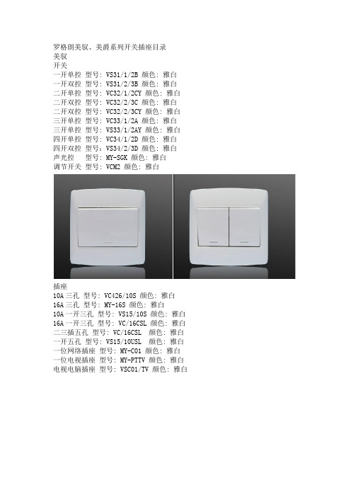
罗格朗美驭、美爵系列开关插座目录美驭开关一开单控型号: VS31/1/2B 颜色: 雅白一开双控型号: VS31/2/3B 颜色: 雅白二开单控型号: VC32/1/2CY 颜色: 雅白二开双控型号: VC32/2/3C 颜色: 雅白二开双控型号: VC32/2/3CY 颜色: 雅白三开单控型号: VC33/1/2A 颜色: 雅白三开单控型号: VS33/1/2AY 颜色: 雅白四开单控型号: VC34/1/2D 颜色: 雅白四开双控型号:VS34/2/3D 颜色: 雅白声光控型号: MY-SGK 颜色: 雅白调节开关型号: VCM2 颜色: 雅白插座10A三孔型号: VC426/10S 颜色: 雅白16A三孔型号: MY-16S 颜色: 雅白10A一开三孔型号: VS15/10S 颜色: 雅白16A一开三孔型号: VC/16CSL 颜色: 雅白二三插五孔型号: VC/16CSL 颜色: 雅白一开五孔型号: VS15/10USL 颜色: 雅白一位网络插座型号: MY-C01 颜色: 雅白一位电视插座型号: MY-PTTV 颜色: 雅白电视电脑插座型号: VSC01/TV 颜色: 雅白美爵开关一开单控型号: 280200 颜色: 银色型号: 280010 颜色: 象牙白带荧光一开双控型号: 280001 颜色: 雅白型号: 280011 颜色: 雅白带荧光二开单控型号: 280202 颜色: 银色型号: 280012 颜色: 雅白带荧光二开双控型号: 280003 颜色: 雅白型号: 280013 颜色: 雅白带荧光三开单控型号: 280204 颜色: 银色型号: 280014 颜色: 象牙白带荧光三开双控型号: 280005 颜色: 雅白型号: 280015 颜色: 雅白带荧光四开单控型号: 280206 颜色: 银色型号: 280016 颜色: 象牙白带荧光四开双控型号: 280007 颜色: 雅白型号: 280017 颜色: 雅白带荧光插座10A三孔型号: 280100 颜色: 雅白16A三孔型号: 280102 颜色: 银色10A一开三孔型号: 280101 颜色: 象牙白型号: 280300 颜色: 银色16A一开三孔型号: 280103 颜色: 象牙白型号: 769852 颜色: 银色二三插五孔型号: 280108-WK 颜色: 象牙白一开插五孔型号: 280113 颜色: 象牙白二二插四孔型号: 280112 颜色: 象牙白电话插座型号: 280170 颜色: 雅白电脑插座型号: 280171 颜色: 雅白电视电话插座型号: MJ-TV/T01 颜色: 象牙白电视电脑插座型号: 280169 颜色: 象牙白。
E2E-X10MF1 接近开关型号参数

接近传感器直流型
E2E-X10MF1 接近开关型号参数
使用专业集成电路,性能更稳定
浪涌,过载,逆极性和短路保护
外壳材质: 黄铜镀镍
防护等级:IP67 (IEC)
使用电压:10-36VDC
安装方式非埋入式/埋入式
检测距离[mm]1mm/2mm
外形尺寸[mm]M8*55
螺纹管尺寸[mm]M8*1*50
电源电压10-36VDC
输出方式NPN NO/PNP NO/NPN NC/PNP NC 响应频率1000Hz
迟滞范围3…20﹪
温度漂移≤±10%
重复精度≤3%
负荷电流≤200mA
消耗电流≤10mA
压降≤2.5V
保护回路浪涌,过载,逆极性和短路保护
输出指示灯黄色LED
环境温度-25…70℃
环境湿度35…95%
防护等级IP67
外壳材质黄铜镀镍
接线方式2米电缆
E2E-X10MF1 接近开关型号参数Dimension drawing。
接近开关E2B 产品样本
E2B-S08KS01-WP-B2 2M E2B-S08KS01-WP-C2 2M E2B-S08LS01-WP-B2 2M E2B-S08LS01-WP-C2 2M E2B-S08KS01-MC-B2 E2B-S08KS01-MC-C2 E2B-S08LS01-MC-B2 E2B-S08LS01-MC-C2 E2B-S08KN02-WP-B2 2M E2B-S08KN02-WP-C2 2M E2B-S08LN02-WP-B2 2M E2B-S08LN02-WP-C2 2M E2B-S08KN02-MC-B2 E2B-S08KN02-MC-C2 E2B-S08LN02-MC-B2 E2B-S08LN02-MC-C2 E2B-S08KS02-WP-B2 2M E2B-S08KS02-WP-C2 2M E2B-S08LS02-WP-B2 2M E2B-S08LS02-WP-C2 2M E2B-S08KS02-MC-B2 E2B-S08KS02-MC-C2 E2B-S08LS02-MC-B2 E2B-S08LS02-MC-C2 E2B-S08KN04-WP-B2 2M E2B-S08KN04-WP-C2 2M E2B-S08LN04-WP-B2 2M E2B-S08LN04-WP-C2 2M E2B-S08KN04-MC-B2 E2B-S08KN04-MC-C2 E2B-S08LN04-MC-B2 E2B-S08LN04-MC-C2
耐油性/防水性 IP规格 环境温度 其他
典型应用
新标准
E2B 良好 IP67 -25~70qC
DC 3线型
3
恶劣环境
E2E
优秀
IP69K -40 ~ 85qC (DC 3线型) -DC 3线型 -DC 2线型 -AC 2线型 -AC/DC 2线型 -直径为3mm的型号
EE-2002中文资料

EE-2001/2002NPN to PNP Conversion Connector for Amplified Photomicrosensors H Converts NPN output to PNP output byeasy connection to amplified photomicrosensorsH Easy solution to achieve PNP output as required in the U.S.andEuropeOrdering InformationApplicable amplified photomicrosensor models Part number EE-SPX301EE-SPX401EE-SPY301EE-SPY401EE-SPY302EE-SPY402EE-SPZ301-A EE-SPZ401-A EE-SPZ301Y-01EE-SPZ401Y-01EE-SPZ301W-01EE-SPZ401W-01EE-SPZ301W-02EE-SPZ401W-02EE-SPZ301EE-SPZ401EE-2001EE-SX670/-A EE-SX671/-A EE-SX672/-A EE-SX673/-AEE-SX470EE-SX471EE-SX472EE-SX473EE-SPY311EE-SPY312EE-SPY411EE-SPY412EE-SY671EE-SY672EE-SPX303/403EE-SPX311/411EE-SB5V/-E EE-SB5VC EE-SB5M EE-SB5MCEE-2002SpecificationsNote:T A =25°C (77°F),65%RH ItemValueSupply voltage*5V to 24VDC ±10%,ripple (p-p):5%max.Consumption current 5mA max.under the following conditions:Connector side:¨=open,short circuit between IN and ©Cord side:¨=26.4V,OUT=open,©=0V Control output 100mA max.(Residual voltage =0.8V max.)Ambient temperature Operating -10°C to 55°C (14°F to 131°F)p Storage -25°C to 65°C (-13°F to 149°F)Ambient humidity Operating 5to 85%RH yStorage5to 95%RH*Use the indicated supply voltages for the specified products below:Supply voltagePart number12to 24VDC ±10%,ripple (p-p):5%max.EE-SPX303,EE-SPX4035to 15VDC ±10%,ripple (p-p):5%max.EE-SB5V/-E,EE-SB5VC 5to 12VDC ±10%,ripple (p-p):5%max.EE-SB5M,EE-SB5MCEE-2001/2002EE-2001/20022OperationJ WIRING DIAGRAM5VDC to 24VDC0VDimensionsUnit:mm (inch)J EE-200112316.2(0.64)20±1040(1.57)200±30∅4.0∅812(0.47)200±30811.8(0.46)5.3(0.21)EE-2001/2002EE-2001/20023J EE-2002812320±1040(1.57)200±30∅4.0∅812(0.47)200±30Note:Insulator material of cable is vinyl chloride.12.5(0.49)4.9(0.19)10.7(0.42)Terminal ArrangementConnector side (sensor side)Cord side (power supply side)Circuit no.(cable color)Function Cable color Function 1(Brown)V CC (+)Brown V CC (+)2(Black)Input (Sensor/output)Black Output 3(Blue)G (0)BlueG (0)EE-2001/2002EE-2001/20024Cat. No. GC A P MS-1 09/02 Specifications subj e ct to c h ange without notice. Printed i n U.S.A.OMRON ELECTRONICS LLCOne East Commerce Drive Schaumburg,IL 60173NOTE:DIMENSIONS SHOWN ARE IN MILLIMETERS.To convert millimeters to inches divide by 25.4.1-800-55-OMRONOMRON CANADA,INC.885Milner Avenue416-286-6465ROMRON ON--LINEGlobal -- USA --/oei Canada --/ociToronto,Ontario M1B 5V82Switching Power Supply S8jjS82KDIN-Rail Mount Power Supply with a Wide Power Range of 3to 240W H Universal voltage range H All models are UL 508listedH Class 2approved on all models below 240-W,except dual-output types H Undervoltage indicators on all.90-W,100-W and 240-W “T”-models have indicator and outputH PFC models meet EN61000-3-2(limits for harmonic current emissions)H Parallel operation capability (100-W and 240-W)H Finger-safe terminal block with cover according to VDE0106/P100H Approvals:UL,CSA,VDE,and CE H3-yearwarrantyu ROrdering InformationRated input lt Power ratings Output voltage Output t Function configuration Part numberp voltage gp gpcurrent Output Undervoltagealarm PFC 100to 240VAC3W 5V 0.6A Single t tIndicator only NoS82K-0030512V 0.25A goutput yS82K-0031215V 0.2A S82K-0031524V0.13A S82K-003247.5W 5V 1.5A S82K-0070512V 0.6A S82K-0071215V 0.5A S82K-0071524V 0.3A S82K-00724+12V/--12V 0.3A/0.2A Dual output S82K-00727+15V/--15V0.2A/0.2A p S82K-0072815W 5V 2.5A Single t tS82K-0150512V 1.2A goutput S82K-0151224V0.6A S82K-0152430W 5V 5.0A S82K-0300512V 2.5A S82K-0301224V1.3A S82K-0302450W 24V2.1AS82K-05024(This table continues on the next page.)S8jjS8jj3Rated input lt Power ratings Output voltage Output t Function configuration Part numberp voltage gp gpcurrent Output Undervoltagealarm PFC 120/240VAC l t bl90W 24V 3.75A Single t tIndicator and t tNo S82K-P09024/selectable goutput output Yes S82K-09024100W24V4.2A No S82K-P10024YesS82K-10024120/230VACl t bl 240W24V10ANoS82K-24024T /selectable NoneS82K-24024100to 230VACYesS82K-P24024S8jjS8jj4S82JDIN-Rail Mounting Industrial Power Supplies with Capacity Up to 600W H Models range from 10to 600W H UL 508approvalH Class 2approval available for models below 100WH Universal input or selectable input H Wide range of output voltages:5V,12V,15V,or 24VHUL,CSA,VDE,andCEApprovalsH3-Year warrantyOrdering InformationJ OPEN-FRAME TYPE POWER SUPPLIESRated input voltage PoweriOutput Part number p gratings Voltage Current Front-mounting bracket DIN-rail mounting bracket 5V2A S 82J-01005A S 82J-01005AD 12V 1A S 82J-01012A S 82J-01012AD 10W15V 0.7A S 82J-01015A S 82J-01015AD 24V 0.5A S 82J-01024A S 82J-01024AD 5V5A S 82J-02505A S 82J-02505AD 100to 240VAC12V 2.1A S 82J-02512A S 82J-02512AD 25W15V 1.7A S 82J-02515A S 82J-02515AD 24V 1.1A S 82J-02524A S 82J-02524AD 5V10A S 82J-05005A S 82J-05005AD 50W12V 4.2A S 82J-05012A S 82J-05012AD 24V 2.1A S 82J-05024A S 82J-05024AD 120or 240VAC(t ti ll l t d)5V 20A S 82J-10005A S 82J-10005AD (automatically selected)12V 8.5A S 82J-10012A S 82J-10012AD 100W15V 7A S 82J-10015A S 82J-10015AD 100to 240VAC 24V 4.5A S 82J-10024A S 82J-10024AD 120or 240VAC(automatically selected)150W24V6.5AS 82J-15024AS 82J-15024ADS8jjS8jj5J COVERED-FRAME TYPE POWER SUPPLIESRated input voltage PoweriOutput Part number p gratings Voltage Current Front-mounting bracket DIN-rail mounting bracket 5V2A S 82J-01005D S 82J-01005DD 12V 1A S 82J-01012D S 82J-01012DD 10W15V 0.7A S 82J-01015D S 82J-01015DD 24V 0.5A S 82J-01024D S 82J-01024DD 5V5A S 82J-02505D S 82J-02505DD 100to 240VAC12V 2.1A S 82J-02512D S 82J-02512DD 25W15V 1.7A S 82J-02515D S 82J-02515DD 24V 1.1A S 82J-02524D S 82J-02524DD 5V10A S 82J-05005D S 82J-05005DD 50W12V 4.2A S 82J-05012D S 82J-05012DD 24V 2.1A S 82J-05024D S 82J-05024DD 120or 240VAC(t ti ll l t d)5V 20A S 82J-10005D S 82J-10005DD (automatically selected)12V 8.5A S 82J-10012D S 82J-10012DD 100W15V 7A S 82J-10015D S 82J-10015DD 100to 240VAC 24V 4.5A S 82J-10024D S 82J-10024DD 120or 240VAC(automatically selected)150W24V6.5AS 82J-15024DS 82J-15024DDJ ENCLOSED-FRAME TYPE POWER SUPPLIESInput voltage Power rating Output Part numberp gg Voltage Current 120or 230VAC (selectable)300W 24V 14.0A S82J-30024()600W24V27.0AS82J-60024Note:1.A mounting bracket is included with each power supply.2.To order without a mounting bracket (normally included with the 300W or 600W),add an “N”at the end of the part number.3.For other accessories,refer to the Accessories section that follows.S8jjS8jj6S8VSSmall Sized,DIN-Rail Mount Power Supply With LED DisplayH Ultra-compact size 40W x 95H (60W model)H3-digit,7-segment LED display showsstatus at a glance for output voltage,output current,peak current,lifetime years,and run time hoursH Incorporates a maintenance forecast monitor that displays the remaining life of the power supply,displayed in yearsH Run-Time monitor model displays how long the output has been on,displayed in thousands of hoursH90W model has two outputs;one for undervoltage output and the other is for either the lifetime monitor or run time monitorH Approved by UL,cUL,UL508Listed,Class2output(60Wonly)H CEmarkedHThree-year warrantyOrdering InformationPower ratings Type Output voltage Output current Part number 60WStandard24V2.5AS8VS-06024With maintenance forecast monitor S8VS-06024A With total runtime monitorS8VS-06024B 90WStandard3.75AS8VS-09024With maintenance forecast monitor S8VS-09024A With total runtime monitorS8VS-09024BS8jjS8jj7S8TSBlock-type Power Supply EasilyConnects With Multiple Units and Offers Many Output Combinations H AC/DC Bus SystemH Up to four blocks can be connected to increase power from 60to 240WH N+1redundant capability to highly reliable systemH Flexible connection for mult-output power supply (5V,12V,24V outputs)H Size consistency minimizes stock types H UL 508listed,Class 2output and Class 1Div.2approvedHComplieswith EN6100-3-2(limits for harmonic current)H3-year warrantyOrdering InformationJ BASIC BLOCKDescription Part numberOutput voltage Output current With line bus connectors Without line bus connector 24V 2.5AS8TS-06024F-E1S8TS-06024F 12V S8TS-03012F-E1S8TS-03012F 5V5A—S8TS-02505FJ BUS LINE CONNECTORTypePart number AC line +DC line bus (for parallel operation)S8T-BUS01AC line bus (for series operation or isolated operation)S8T-BUS02J ACCESSORIESType Length WidthPart number DIN rail0.5m (1.64ft.)7.3mm (0.29in)PFP-50N 1m (3.28ft.)7.3mm (0.29in)PFP-100N 1m (3.28ft.)16mm (0.63in)PFP-100N2End platePFP-MS8jjS8jj 8Cat.No.GC APMS-109/02Specifications subject to change without notice.Printed in U.S.A.OMRON ELECTRONICS LLCOne East Commerce Drive Schaumburg,IL 60173NOTE:DIMENSIONS SHOWN ARE IN MILLIMETERS.To convert millimeters to inches divide by 25.4.1-800-55-OMRONOMRON CANADA,INC.885Milner Avenue 416-286-6465ROMRON ON--LINE Global -- USA --/oei Canada --/oci Toronto,Ontario M1B 5V8元器件交易网。
E2B-S08KS01-WP-C2接近开关

E2B 接近传感器 O5TT世界新标准经济型接近传感器,完美使用各种场合,全机种·高品质·低价格 E2B 种类:信息更新: 2017年11月18日尺寸 检测 距离 连接方式 (见“注1”) 螺纹 长度 输出类型动作模式NO动作模式NCM8(不锈钢)(见 “注2”) 单倍距离型屏蔽型 1.5mm 导线引出型标准 型 PNP E2B-S08KS01-WP-B1 2M E2B-S08KS01-WP-B2 2M NPN E2B-S08KS01-WP-C1 2M E2B-S08KS01-WP-C2 2M 长螺 纹型 PNP E2B-S08LS01-WP-B1 2M E2B-S08LS01-WP-B2 2M NPN E2B-S08LS01-WP-C1 2M E2B-S08LS01-WP-C2 2MM8接插件型(3针) 标准 型 PNP E2B-S08KS01-MC-B1E2B-S08KS01-MC-B2 NPN E2B-S08KS01-MC-C1E2B-S08KS01-MC-C2 长螺 纹型 PNP E2B-S08LS01-MC-B1E2B-S08LS01-MC-B2 NPN E2B-S08LS01-MC-C1E2B-S08LS01-MC-C2 非屏蔽型 2mm 导线引出型标准 型 PNP E2B-S08KN02-WP-B1 2ME2B-S08KN02-WP-B2 2M NPN E2B-S08KN02-WP-C1 2ME2B-S08KN02-WP-C2 2M 长螺 纹型 PNP E2B-S08LN02-WP-B1 2M E2B-S08LN02-WP-B2 2M NPN E2B-S08LN02-WP-C1 2M E2B-S08LN02-WP-C2 2M M8接插件型(3针)标准 型 PNP E2B-S08KN02-MC-B1E2B-S08KN02-MC-B2 NPN E2B-S08KN02-MC-C1E2B-S08KN02-MC-C2 长螺 纹型 PNP E2B-S08LN02-MC-B1 E2B-S08LN02-MC-B2 NPN E2B-S08LN02-MC-C1 E2B-S08LN02-MC-C2 两倍距离型屏蔽型 2mm 导线引出型标准 型 PNP E2B-S08KS02-WP-B1 2M E2B-S08KS02-WP-B2 2M NPN E2B-S08KS02-WP-C1 2ME2B-S08KS02-WP-C2 2M 长螺 纹型 PNP E2B-S08LS02-WP-B1 2M E2B-S08LS02-WP-B2 2M NPN E2B-S08LS02-WP-C1 2M E2B-S08LS02-WP-C2 2M M8接插件型(3针) 标准 型 PNP E2B-S08KS02-MC-B1E2B-S08KS02-MC-B2 NPN E2B-S08KS02-MC-C1E2B-S08KS02-MC-C2 长螺 纹型 PNP E2B-S08LS02-MC-B1E2B-S08LS02-MC-B2 NPN E2B-S08LS02-MC-C1E2B-S08LS02-MC-C2 非屏蔽型 4mm 导线引出型标准 型 PNP E2B-S08KN04-WP-B1 2ME2B-S08KN04-WP-B2 2M NPN E2B-S08KN04-WP-C1 2ME2B-S08KN04-WP-C2 2M 长螺 纹型 PNP E2B-S08LN04-WP-B1 2M E2B-S08LN04-WP-B2 2M NPN E2B-S08LN04-WP-C1 2M E2B-S08LN04-WP-C2 2M M8接插件型(3针)标准 型 PNP E2B-S08KN04-MC-B1E2B-S08KN04-MC-B2 NPN E2B-S08KN04-MC-C1E2B-S08KN04-MC-C2 长螺 纹型 PNP E2B-S08LN04-MC-B1E2B-S08LN04-MC-B2 NPN E2B-S08LN04-MC-C1E2B-S08LN04-MC-C2注:1. 导线引出型的电缆长度有2m和5m两种。
ES2E中文资料(MIC GROUP)中文数据手册「EasyDatasheet - 矽搜」
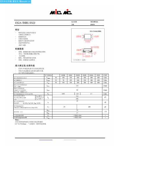
NOTES : 1.Rise Time=7ns max. Input Impedance= 1 magohm. 22pF
2.Rise time=10ns max. Source Impedance= 50 ohms
芯片中文手册,看全文,戳
ES2A THRU ES2J
特征
塑料包装已承防护实验室
可燃性分类94V-0
玻璃钝化结 内置应变消除 超级开关速度快高效率 高温焊接防护证:
250℃/10秒
机械数据
案例:JEDED DO-214AA转移模压塑料 码头:焊接镀,每MIL-STD-750, 方法2026
trr
典型Junstion电容
(Measured at 1.0MHz and applied reverse voltage of4.0V)
CJ
典型热阻(注1)
RθJA RθJL
工作结温范围
TJ
存储Tempetature穰
T STG
笔记:
自结1到环境热阻结点到铅安装在PCB同 0.3”×0.3”(8.0mm × 8.0毫米)铜焊焊盘领域.
FIG.1-TYPICAL FORWARD CURRENT DERATING CURVE
FIG.2-MAXIMUM NON-REPETITIVE PEAK FORWARD SURGE CURRENT
(A) AVERAGE FORWARD CURRENT,
AMBIENT TEMPERATURE, (° C) FIG.3-TYPICAL INSTANTANEOUS FORWARD CHARACTERISTICS
E202E资料
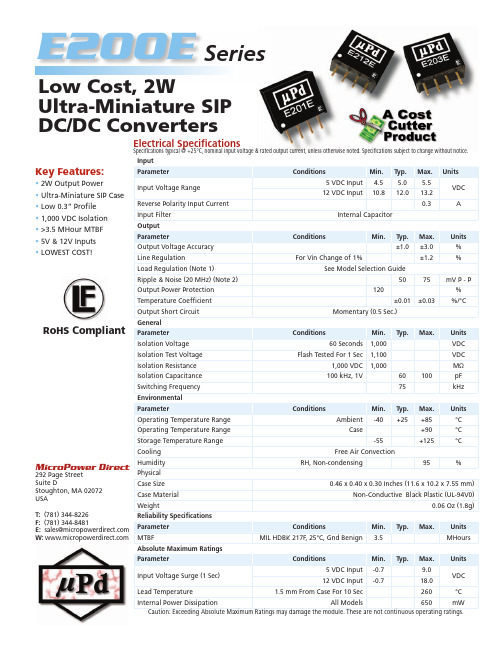
MicroPower Direct292 Page Street Suite DStoughton, MA 02072USAT: (781) 344-8226F: (781) 344-8481E: sales@ W: Key Features:• 2W Output Power • Ultra-Miniature SIP Case • Low 0.3” Profi le • 1,000 VDC Isolation • >3.5 MHour MTBF • 5V & 12V Inputs • LOWEST COST!E200E Low Cost, 2WUltra-Miniature SIP DC/DC Con v ert e rsInputParameterConditionsMin.Typ.Max.Units Input Voltage Range5 VDC Input 4.5 5.0 5.5VDC 12 VDC Input10.812.013.2Reverse Polarity Input Current 0.3AInput Filter Internal CapacitorOutputParameterConditionsMin.Typ.Max.Units Output Voltage Accuracy ±1.0±3.0%Line RegulationFor Vin Change of 1%±1.2%Load Regulation (Note 1)See Model Selection GuideRipple & Noise (20 MHz) (Note 2)5075mV P - P Output Power Protection 120%Temperature Coeffi cient ±0.01±0.03%/°COutput Short Circuit Momentary (0.5 Sec.)General Parameter ConditionsMin.Typ.Max.Units Isolation Voltage 60 Seconds1,000VDC Isolation Test Voltage Flash Tested For 1 Sec1,100VDC Isolation Resistance 1,000 VDC 1,000M ΩIsolation Capacitance 100 kHz, 1V60100pF Switching Frequency 75kHz Environmental ParameterConditionsMin.Typ.Max.Units Operating Temperature Range Ambient-40+25+85°C Operating Temperature Range Case+90°C Storage Temperature Range -55+125°CCooling Free Air ConvectionHumidity RH, Non-condensing95%Physical Case Size 0.46 x 0.40 x 0.30 Inches (11.6 x 10.2 x 7.55 mm)Case Material Non-Conductive Black Plastic (UL-94V0)Weight0.06 Oz (1.8g)Reliability Specifi cations Parameter ConditionsMin.Typ.Max.Units MTBFMIL HDBK 217F , 25°C, Gnd Benign3.5MHours Absolute Maximum Ratings ParameterConditionsMin.Typ.Max.Units Input Voltage Surge (1 Sec) 5 VDC Input -0.79.0VDC 12 VDC Input-0.718.0Lead Temperature 1.5 mm From Case For 10 Sec260°C Internal Power DissipationAll Models650mWCaution: Exceeding Absolute Maximum Ratings may damage the module. These are not continuous operating ratings.Electrical Specifi cationsSpecifi cations typical @ +25°C, nominal input voltage & rated output current, unless otherwise noted. Specifi cations subject to change without notice.SeriesRoHS CompliantNotes:1. Output load regulation is specifi ed for a load change of 10% to 100%.2. When measuring output ripple, it is recommended that an external 0.33 µF ceramic capacitor be placed from the +Vout pin to the -Vout pin.3. T hese units should not be operated with a load under 10% of full load. Operation at no-load may cause damage to the unit.4. These converters are specifi ed for operation without external components. However, in some applications the addition of input/ouput capacitors will enhance stability and reduce output ripple. Recommended capacitor values are:Vin Input Capacitor Vout Output Capacitor 5 VDC 4.7 µF 5 VDC 10.0 µF 12 VDC2.2 µF12 VDC 2.2 µF 15 VDC1.0 µFFor applications requiring very low output noise levels, a simple LC fi lter should be effective.5. It is recommended that a fuse be used on the input of a power supply for protection. See the Model Selection table above for the correct rating.Model Selection GuideNotes:• All dimensions are typical in inches (mm)• Tolerance x.xx = ±0.01 (±0.25)• Pin 1 is marked by a “dot” or indentation on the side of the unitModel Number InputOutput LoadRegulation(% Max)Effi ciency(%, Typ)Fuse Rating Slow-Blow (mA)Voltage (VDC)Current (mA)Voltage (VDC)Current (mA, Max)Current (mA, Min)Nominal RangeFull-Load No-LoadE201E 5 4.5 - 5.551338 5.0400.040.015781,000E202E 5 4.5 - 5.55063812.0167.017.015791,000E203E 5 4.5 - 5.55063815.0133.014.015791,000E211E 1210.8 - 13.221420 5.0400.040.01578500E212E 1210.8 - 13.22082012.0167.017.01580500E213E1210.8 - 13.22062015.0133.014.01581500Mechanical DimensionsPin Description1-Vin 2+Vin 3-Vout 4+VoutPin ConnectionsDerating CurveMicroPower Direct292 Page Street Ste D Stoughton, MA 02072 • TEL: (781) 344-8226 • FAX: (781) 344-8481 • E-Mail: sales@。
E2EL-X10F12M中文资料(omron)中文数据手册「EasyDatasheet - 矽搜」
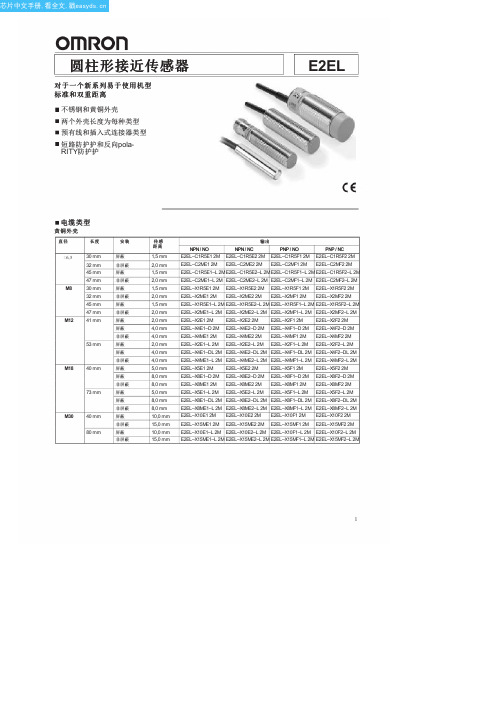
E2EL–X4E1–DL 2M E2EL–X4E2–DL 2M E2EL–X4F1–DL 2M E2EL–X4F2–DL 2M
E2EL–X4ME1–L 2M E2EL–X4ME2–L 2M E2EL–X4MF1–L 2M E2EL–X4MF2–L 2M
Байду номын сангаас
E2EL–X5E1 2M E2EL–X5E2 2M E2EL–X5F1 2M E2EL–X5F2 2M
E2EL–X4E1–D 2M E2EL–X4E2–D 2M E2EL–X4F1–D 2M E2EL–X4F2–D 2M
E2EL–X4ME1 2M E2EL–X4ME2 2M E2EL–X4MF1 2M E2EL–X4MF2 2M
E2EL–X2E1–L 2M E2EL–X2E2–L 2M E2EL–X2F1–L 2M E2EL–X2F2–L 2M
1
芯片中文手册,看全文,戳
E2EL
不锈钢外壳
直径
长度
6,5 30 mm 45 mm
M8 30 mm 45 mm
M12 41 mm 53 mm
M18 40 mm 73 mm
插头类型
黄铜外壳
直径 /
触点
长度
6,5 / 插头 M8
M8 / 插头 M8
M8 / 插头 M12
M12 / 插头 M12
45 mm 47 mm 54 mm 56 mm 45 mm 47 mm 54 mm 56 mm 44 mm 46 mm 60 mm 62 mm 49 mm
60 mm
M18 / 53 mm 插头 M12
80 mm
M30 / 插头 M12
55 mm 80 mm
不锈钢外壳
直径 /
5E-01中文资料
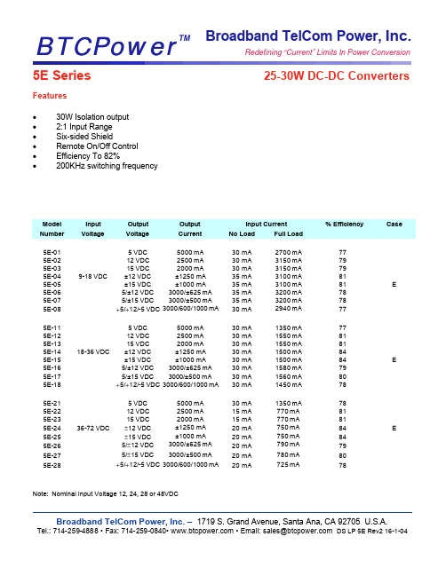
Broadband TelCom Power, Inc. BTCPower TM Redefining “Current” Limits In Power Conversion BTCPower5E Series 25-30W DC-DC Converters Features• 30W Isolation output• 2:1 Input Range• Six-sided Shield• Remote On/Off Control• Efficiency To 82%• 200KHz switching frequencyModel Input Output Output Input Current % Efficiency Case Number Voltage Voltage Current No Load Full Load5E-01 5 VDC5000 mA30 mA 2700 mA775E-02 12 VDC2500 mA30 mA 3150 mA795E-03 15 VDC2000 mA30 mA 3150 mA795E-04 9-18 VDC ±12 VDC±1250 mA35 mA 3100 mA815E-05 ±15 VDC±1000 mA35 mA 3100 mA81 E 5E-06 5/±12 VDC3000/±625 mA35 mA 3200 mA785E-07 5/±15 VDC3000/±500 mA35 mA 3200 mA785E-08 +5/+12/-5 VDC3000/600/1000 mA30 mA 2940 mA775E-11 5 VDC5000 mA30 mA 1350 mA775E-12 12 VDC2500 mA30 mA 1550 mA815E-13 15 VDC2000 mA30 mA 1550 mA815E-14 18-36 VDC ±12 VDC±1250 mA30 mA 1500 mA845E-15 ±15 VDC±1000 mA30 mA 1500 mA84 E 5E-16 5/±12 VDC3000/±625 mA30 mA 1580 mA795E-17 5/±15 VDC3000/±500 mA30 mA 1560 mA805E-18 +5/+12/-5 VDC3000/600/1000 mA30 mA 1450 mA785E-21 5 VDC5000 mA30 mA 1350 mA785E-22 12 VDC 2500 mA15 mA 770 mA 815E-23 15 VDC 2000 mA15 mA 770 mA815E-24 36-72 VDC ±12 VDC ±1250 mA20 mA 750 mA84 E 5E-25 ±15 VDC±1000 mA20 mA 750 mA845E-26 5/±12 VDC3000/±625 mA20 mA 790 mA795E-27 5/±15 VDC3000/±500 mA20 mA 780 mA805E-28 +5/+12/-5 VDC 3000/600/1000 mA20 mA 725 mA78Note: Nominal Input Voltage 12, 24, 28 or 48VDCBroadband TelCom Power, Inc. –1719 S. Grand Avenue, Santa Ana, CA 92705 U.S.A. Tel.: 714-259-4888 • Fax: 714-259-0840• • Email: sales@ DS LP 5E Rev2 16-1-045E Series 25-30W DC-DC ConvertersBTCPower BTCPowerT MBroadband TelCom Power, Inc. – 1719 S. Grand Avenue, Santa Ana, CA 92705 U.S.A.Tel.: 714-259-4888 • Fax: 714-259-0840• • Email: sales@ DS LP 5E Rev2 16-1-04SpecificationsInput Specifications:Input Voltage Range…………….……12V……...………………..9-18V 24V……………………..18-36V 48V…………………......36-72V Input Filter………………………………………………………..Pi Type Output Specifications: Voltage AccuracySingle output………………………..…………………….+/- 1.0 % max. Daul output………………………………………………..+/- 3.0 % max. Triple, 5V………………………………………………….+/- 1.0 % max. 12V/15V/ -5V……………………………………..………+/- 3.0 % max. Voltage Balance ( Dual )………………………………...+/- 1.0 % max. External trim Adj. Range……………………………..…………+/- 10% Ripple & Noise, 20 MHz BW……………………….… 75 mV p-p max. Temperature Coeffcient………………………… +/- 0.02 % / ºC max. Short Circuit Protection………………………………..……Continuous Line Regulation ¹ Single / Dual Output………….……..+/- 0.2 % max. Triple………………………….………..+/- 1.0% max. Load Regulation ² Single / Dual Output…………….….+/- 1.0 % max. Triple………………………..…………+/- 5.0 % max. General Specifications :Efficiency………………………………………………..……..see table Isolation Resistance…………………………………………..100Mohm Switching Frequency……………………………………..200 KHz, min.Operating Temperature Range…………………………-25ºC ~ +71ºC Case Temperature………………………………………….100 ºC max. Cooling……………………………………………….Free air convection Storage Temperature Range……………………..…..-55 ºC ~ +105ºC Isolation Voltage………………………….………………..500VDC min. EMI/RFI…………………………………….....Six-sided continus shield Dimensions…………………2.65” x3” x 0.83 “(65 x 76.2 x 21.1 mm) Case Material……..Black Coated Copper with Non-conducted baseTriple output loading tableOuput Voltage Amperes (pin no.)(V) Min. (2) Nom. 6 +5 0.25 1.5 3 & 5 +12 or -12 0.1 0.31 3 & 5 +15 or -15 0.1 0.25 3 & 5+12 or -50.1/0.1 0.31/0.5Note: 1. measured from high lin to low line2. measured from full load to ¼ load3. maximum total power from all outputs is limited to 25/30W but no output should be allowed to exceed its maximum current4. minmum current on each output is required to maintain specified regulationOutline Information and Pin-outPin ConnectionPin Single Dual Triple 1 +Input +Input +Input 2 -Input -Input -Input 3 No pin +Output+Output 4 Trim Common Common 5 No pin -Output -Output 6 +Output No pin +5V output 7 -OutputNo pin No pin 8 Remote On/Off ControlRemote On/Off ControlLogic compatibility CMOS or Open collector TTL E c-0n >5.5 Vdc or open circuit E c-Off <1.8 Vdc Shutdown Idle current 10mA Input resistance 100K ohms (Ein 0Vdc to 9Vdc) Control common referenced to Input minus External Output TrimmingOutput may optionally be externally trimmed (+/-10%) with a fixed resistor or an external trimpot as shown.。
松下-E2C型小型头接近开关(放大器分离型)-说明书
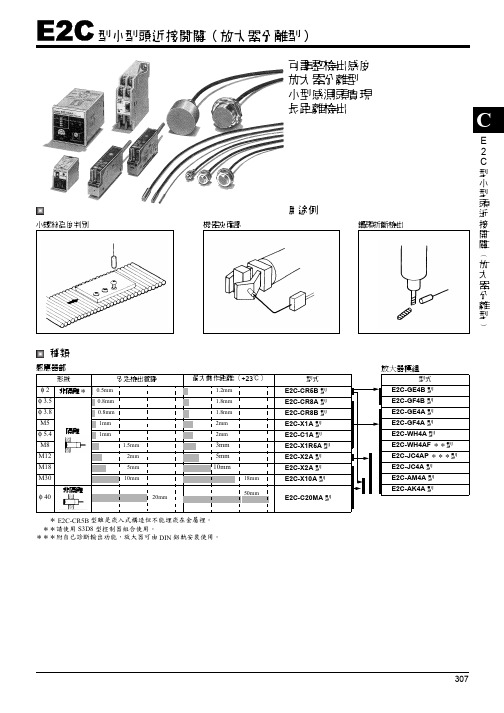
307E 2C 型小型頭近接開關︵放大器分離型︶C可調整檢出感度放大器分離型小型感測頭實現長距離檢出用途例小螺絲高度判別 機器夾確認 鑽頭折斷檢出種類感應器部* E2C-CR5B 型雖是崁入式構造但不能埋崁在金屬裡。
**請使用S3D8型控制器組合使用。
***附自己診斷輸出功能,放大器可由DIN 鋁軌安裝使用。
形狀安定檢出範圍最大動作距離(+23℃)型式φ 2非隔離* 0.5mm1.2mm E2C-CR5B 型φ 3.5隔離0.8mm1.8mm E2C-CR8A 型φ 3.8 0.8mm1.8mm E2C-CR8B 型M5 1mm 2mm E2C-X1A 型φ 5.4 1mm2mm E2C-C1A 型M8 1.5mm3mm E2C-X1R5A 型M12 2mm5mmE2C-X2A 型M18 5mm 10mmE2C-X2A 型M30 10mm18mm E2C-X10A 型φ 40非隔離20mm50mmE2C-C20MA 型放大器模組型式E2C-GE4B 型E2C-GF4B 型E2C-GE4A 型E2C-GF4A 型E2C-WH4A 型E2C-WH4AF **型E2C-JC4AP ***型E2C-JC4A 型E2C-AM4A 型E2C-AK4A 型E2C 型小型頭近接開關(放大器分離型)E2C308E 2C額定/性能感應器部*使用放大器模組無接點控制輸出時之最低值,測定條件是使用標準檢出物,檢出物體的間隔是標準檢出物體的2倍,設定距離是最大檢出距離 的1/2。
**放大器與感測頭組合時,纜線長度請參照下表。
高周波同軸纜線阻抗特是50Ω。
<感測頭與放大器組合使用時纜線長度一覽表>註:標準纜線長度3m 是標準品,5m 、10m 接受定製生產。
*放大器之纜線長切換操作,請參考放大器模組織操作。
形式項目E2C-CR5B 型E2C-CR8A 型E2C-CR8B 型E2C-X1A 型E2C-C1A 型E2C-X1R5A型E2C-X2A 型E2C-X5A 型E2C-X10A 型E2C-C20MA型檢出物體磁性金屬(非磁性金屬特性請參照特性圖)標準檢出物體鐵5×5×1mm 鐵5×5×1mm 鐵5×5×1mm 鐵8×8×1mm 鐵12×12×1mm 鐵18×18×1mm 鐵30×30×1mm 鐵50×50×1mm 安定檢出範圍(額定的全溫度範圍)0~0.5mm 0~0.8mm 0~1mm 0~1.5mm 0~2mm 0~5mm 0~10mm 0~20mm 安全檢出圍(0~+40℃)0~0.7mm 0~1.2mm 0~1.5mm 0~2mm 0~2.5mm 0~7mm 0~15mm 0~28mm 最大動作距離(+23℃一定) 1.2mm1.8mm 2mm3mm5mm10mm 18mm 50mm 應答周波數*1kHz800Hz350Hz100Hz50Hz使用周圍溫度-10~±55℃-25℃~+70℃(但不能結冰)使用周圍濕度35~95%RH溫度的影響-10~±55℃溫度範圍+23℃時檢出距離±25%以下-25±~+70℃的溫度範圍,在+23℃的檢出距離±15%以下振動耐久:10~55Hz 複振幅1.5mm X 、Y 各方向 2h衝擊耐久:500m/s 2(50G) X 、Y 各方向3次保護構造IEC 規格IP64[JEM 規格IP64(防沬形)]IEC 規格IP67 [JEM 規格IP67g (耐浸形、耐油形)]連接纜線長度**被覆纜線3mm高週波同軸纜線遠(標準長),最大 5m高週波同軸纜線3M (標準長),最大10m 重量(3m cable)約10g約40g約45g約50g約60g約140g約270g約300g材質外殼不銹鋼黃銅檢出面ABS 樹脂纜線聚乙烯檢出頭放大器E2C-CR5B 型E2C-CR8A 型E2C-CR8B 型E2C-X1A 型E2C-C1A 型E2C-X1R5A 型E2C-X2A 型E2C-X5A 型E2C-X10A 型E2C-C20MA 型E2C-GE4B 型3m 限定—————————E2C-GF4B 型—————————E2C-GE4A 型—3m 限定————E2C-GF4A 型—————E2C-WH4A 型—3m 或5m 纜線長度切換開關依各設位置*————E2C-WH4AF 型—————E2C-JC4AP 型—1~3m :纜線長切換端子短路*3~5m :纜線長切換端子開放*———E2C-JC4A 型—3m 限定———E2C-AM4A 型3m 或5m 限定(開關全部在左邊)0~5m 纜線長度切換開關依各設位置0~10m 纜線長度切換開關依各設位置*E2C-AK4A 型E2C309E 2C放大器部*1. 可以使用 DC24V ±10%(平均值)之全波整流電源。
E2K-C25ME1资料

Indicators
Detection indicator (red)
Operation indicator (red)
Operation mode (with sensing object approaching)
E1/Y1 Models: NO E2/Y2 Models: NC
Refer to the timing charts under I/O Circuit Diagrams on page 5 for details.
Differential travel 15% max. of sensing distance (when adjusted to 20 mm r10% with standard sensing object)
Response frequency *2
40 Hz
AC power: 25 Hz, DC power: 40 Hz
/
(c)Copyright OMRON Corporation 2007 All Rights Reserved.
2
元器件交易网
E2K-C
Noise-resistant Models
Item
Model
E2K-C20MC1
E2K-C20MC2
E2K-C20MT1
E2K-C20MT2
Sensing distance *1
20 mm
Sensing area
3 to 20 mm
Detectable object Conductors and dielectrics
Standard sensing object
Grounded metal plate: 50 u 50 u 1 mm
FE2.1中文资料

FE2.1高速七端口USB2.0集线器控制芯片一引言FE2.1芯片是高度集成,高品质,高性能,低能耗,总体花费低的高速七端口USB2.0集线器解决方案。
FE2.1适应多样任务译码器(MMT)风格,借此达到最大的数据输出。
六个(而不是两个)非周期数据处理缓冲器被用来将潜在的传输干扰降至最低。
整个设计基于状态机控制原理,降低了相应延迟时间。
该芯片中没有使用微控制器。
为了保证高品质,整个芯片覆盖测试扫描链—包括高速模块(频率480MHz),所以在运行前可以检测所有逻辑组件。
芯片拥有特殊的自检建立模式,可以在封装和测试阶段测试高速、全速和低速模拟前端结束(AFE)元件。
通过使用0.18微米制造工艺和全面电源/时钟控制机制实现低功耗。
若无必要,芯片的大部分不会被锁住。
特点:■低功耗:□七个下行端口全部在高速模式工作时电流为155mA,□一个下行端口工作在高速模式下电流为66mA,■完全符合通用串行总线规范修订版2.0(USB2.0):□上传端口支持高速度(480MHz信)和全速(12MHZ)模式;□7下行端口支持高速(480MHz信),全速(12MHz)和低速(1.5MHz)模式;。
■集成USB2.0收发器;■集成上传1.5KΩ上拉电阻、下行1.5KΩ下拉电阻和串行电阻;■集成5V转3.3V和1.8V的电压调节器;■集成上电复位电路■集成12MHz的振荡器与反馈电阻和晶体负载电容;■集成12MHz转480MHz锁相回路;■多种任务译码器□一个任务译码器负责一个下行端口;□单任务译码器采用备用接口0,多任务译码器用备用接口1;□每个任务译码器可以处理64个开始分散任务、32个完全分散任务和6个无周期任务;■只支持自供电模式■主板配置选项——□成组或单独的电源控制模式选项;□全局、多模块或单模块过流保护选项;□配置可拆卸或不可拆卸下行设备;□选择下行端口数目;■电可擦可编程只读存储器配置选项——□供应商ID、产品ID和设备发行数量;□可拆卸或不可拆卸下行设备配置;□编号;□下行端口数目:■综合状态指标支持□标准下行端口状态指示灯(每个下行端口有绿色和琥珀色LED控制指示灯);□集线器工作/暂停状态LED指示灯;■支持微软Windows98SE/ME,2000,XP和Vista操作系统;■支持Mac OS 8.6及以上操作系统;■支持Linux 内核2.4.20及以上系统;封装:■64针脚LQFP(大小:10×10mm)■48针脚LQFP (大小: 7×7mm )框图(面积大小:10×10mm)64针脚封装引脚分配图48针脚封装引脚分配图引脚说明表格备注:1.OVCJ[7:2]针脚配有可选择的内部上拉电阻。
ewb中元件介绍

信号源库(Source)图4.2.1基本元器件图标如图4.2.1所示,具体参数如表4.2.1所示。
表4.2.14.3 二极管库(Diode)二极管库的元器件图标如图4.3.1所示,具体参数如表4.3.1所示。
图4.3.1表4.3.14.4 三极管库(Transistors)三极管库元器件图标如图4.4.1所示,具体参数如表4.4.1所示。
表4.4.14.5 模拟集成元器件库(Analog ICs)模拟集成电路库元器件图标如图4.5.1所示,具体参数如表4.5.1所示图4.5.1表4.5.14.6 混合集成元器件库(M ixed ICs)混合集成元器件库元器件图标如图4.6.1所示,具体参数如表4.6.1所示。
图4.6.1表4.6.14.7 数字集成元器件库(Didital ICs)数字集成元器件库图标如图4.7.1所示,具体参数如表4.7.1所示。
表4.7.1元器件名称缺省设置值设置、选择范围74xx理想7400~7493 741xx理想74107~74199 742xx理想74238~74298 743xx理想74350~74395 744xx理想74445~74466 4xxx理想4000~455674xx系列集成电路741xx系列集成电路742xx系列集成电路743xx系列集成电路744xx系列集成电路4xxx系列集成电路4.8 逻辑门元器件库(Logic Gates)图4.8.1逻辑门电路库元器件图标如图4.8.1所示,具体参数如表图图4.8.1所示。
表4.8.14.9 数字元器件库(Digital)数字元器件库图标如图4.9.1所示,具体参数如表4.9.1所示。
图4.9.1表4.9.14.10 指示元器件库(Indicators)指示元器件库元器件如图4.10.1所示,具体参数如表4.10.1所示。
图4.10.1 表 4.10.1二表将显示在辑表达式将显示在显示区的逻辑表达式对应的真值表将显示在路工作区。
C2592资料
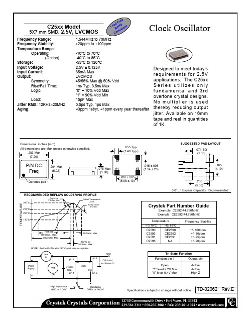
Ramp-Up 3°C/Sec Max. Critical Temperature Zone Ramp-Down 6°C/Sec.
Crystek Part Number Guide
Example: C2592-44.736MHZ Example: CE2592-44.736MHZ Temperature
Vdd OUT
C2590 C2592 C2591 C2598
CE2590 CE2592 CE2591 NA
Tri-State Function Function pin 1 Open "1" level 2.2V Min "0" level 0.4V Max Output pin Active Oscillator
1.544MHz to 70MHz ±20ppm to ±100ppm -10°C to 70°C -40°C to 85°C -55°C to 120°C 2.5V ± 0.125V 35mA Max LVCMOS 45/55% Max @ 50% Vdd 1ns Typ, 3.5ns Max "0" = 10% Vdd Max "1" = 90% Vdd Min 15pF Max 0.5ps Typ, 1ps Max <3ppm 1st/yr, <1ppm every year thereafter
pin 3 OSC.
GND
PWR Supply
O/P Load incl Probe Cl
VM
Bypass Cap. pin 1
pin 2
High Impedance GND or "LOW"
欧姆龙E2E通用接近开关详解
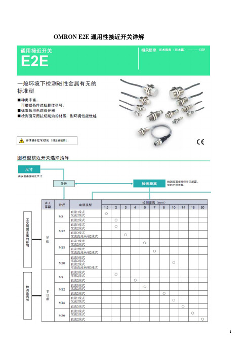
OMRON E2E通用性接近开关详解
现购有:E2E-X10E2 NPN NC型,E2E-X10F1 PNP NO型。
屏蔽型M30螺纹。
现购有:E2E-X10E2 NPN NC型,E2E-X10F1 PNP NO型。
NPN有两种形式:E1为NPN NO型,E2为NPN NC型。
PNP有一种形式:F1为PNP NO型。
E2E-X10E2 NPN NC E2E-X10E1 NPN NO E2E-X10F1 PNP NO
所谓NO、NC均对接近开关在无动作时-即常态时的开关管的状态而言,例如:对于NPN NC无动作时,②端对③端呈闭合状态即NC,此时①端、②端得电。
对于NPN NO无动作时,④端对③端呈开路状态即NO,此时④端、①端失电。
对于PNP NO无动作时,褐色端对黑色端呈开路状态即NO,此时黑色端、蓝色端失电。
对于常开或常闭,可以将开关管的发射极和集电极等效为一个开关。
依据传统的限位开关具有二对触点,一对为常开、而另一对为常闭。
因此、可以选用4芯接插件形式,通过不同的接线方式
例如:E2E-X10E1-M1或E2E-X10E1-M3,完成NPN NO、NPN NC 兼容的功能。
而对于集电极开路传感器的的接法见下图:
E2E-C/X_C_ NPN NC/NO E2E-C/X_B_ PNP NO。
