PSX600说明书
SilverStone Strider Plus ST60F-PS 600W 单相电源说明书

SPECIFICATIONSilverStone Strider PlusST60F-PSATX12V / EPS 12V Switching Power SupplyWith Active PFC 80Plus SilverPS/2011.1 ScopeThis specification defines the performance characteristics of a single phase 600watts, 5 output power supply. This specification also defines worldwide safety andelectromagnetic compatibility requirements for the power supply which is intended for use in computer products.1.General2.1 Input VoltageNominal Voltage Voltage Variation Range 100-240 Vrms 90 - 264 Vrms 2.Input Characteristics2.2 Input FrequencyNominal Frequency Frequency Variation Range 50-60 Hz 47 Hz to 63 Hz* The power supply must operate at above frequency with 90-264 VACrms input voltage range.022.3 Max. Input AC CurrentMax. Input Current Measuring Range 8A 90 - 264 Vrms2.4 Inrush CurrentThe power supply must meet inrush requirements for any rated AC voltage, during turn on at any phase of AC voltage, during a single cycle AC dropout condition, during repetitive ON/OFF cycling of AC, and over the specified temperature range.The peak inrush current shall be less than the ratings of its critical components (including input fuse, bulk rectifiers, and surge limiting device).2.5 EfficiencySST-ST60F-PS provides an efficiency of 85% minimum when measured at full load under 115V/60Hz condition.3.1 Normal Operation Output3.Output characteristicsMaximum continuous total DC output power should not exceed 600W.Maximum continuous combined load on +3.3VDC and +5VDC outputs shall not exceed 130W.Maximum combined load on +12V outputs shall not exceed 588W.NOTE:Noise test should be measured with 20 MHz bandwidth frequency oscilloscope. The output terminal shall add a tantalum capacitor of 10uF in parallel with a ceramic capacitor of 0.1uF.033.2 Remote On/Off Controlled modeThe PSON# signal is required to remotely turn on/off the power supply,PSON# is an active low signal that turns on the output power rails. When this is not pulled low by the system, or left open, the outputs (except the +5VSB) turn off. This signal is pulled to a standby voltage by a pull-up resistor internal to the power supply.TTL level "H" 2.0 V - 5.25 V "L" 0.0 V – 1.0 V3.3 RegulationThe cross regulation defined as follows, the output regulation should be within the specified range.3.4 Rise TimeDC output rise time is less than 20 mS at nominal line and full load.3.5 Hold-up TimeDC +5V output maintains at least 12mS after power off which hold within para 3.1 under 230V/50Hz condition.3.6 5VSB5VSB is requierd for the implementation of PS-ON described above. 5VSB is a standby voltage that may be used to power circuits that require power input during the powered-down state of all power rails. The 5 VSB pin should deliver 5V ± 5% at a minimum of 3.0 A for PC board circuits to operate. Conversely,PC board should draw no more than 3.0A maximum form this pin. This power may be used to operate circuits such as soft power control.043.7 PG-OKPG-OK is a power good signal and should be asserted high by power supply to indicate that the +5 VDC and +3.3 VDC outputs are above the under-voltage thresholds of the power supply. When this signal is asserted high, there should be sufficient mains energy stored by the converter to guarantee continuous power operation within specification. Conversely, when either the +5VDC or the +3.3VDC output voltage falls below the under-voltage threshold, or when mains power has been removed for a time sufficiently long so that power supplyoperation is no longer guaranteed, PG-OK should be deasserted to a low state.See Figure 1 for a representation of the timing characteristics of the PG-OK,PS-ON, and germane power rail signals.3.8 3.3V SenseA default 3.3V sense line should be implemented pin 13 of the connector.3.9 Capacitive LoadThe power supply should be able to power up and operate normally with the following capacitances simultaneously present on the DC outputs.4.1 Input ProtectionIn primary circuit of the power supply , a protected fuse is inserted. Only internal fault of the power supply will cause the fuse blown. Any overload or short circuit at DC output will keep from fuse brown or fire hazard.4.Protection054.2 Output Protection4.2.1 Under voltage protection 4.2.1 Under voltage protectionThe +5V/+12V/+3.3V DC output are protected against the under voltage condition . range value can't be exceed 3.3~3.7V at 5V terminal and 8.5~9.5V at 12V, 2.0~2.4V at 3.3V.4.2.2 Over Voltage ProtectionThe +12V/ DC output are protected against the over voltage condition . Maximum value can't be over 15.5V at 12V.4.2.3 Over Power ProtectionThe power supply can be used electronic circuit to limit the output current against exceeding 60% of surge output power or protected against excessive power delivery since short circuit of any output or over total power at high line.4.2.4 Short Circuit ProtectionShort circuit placed on +5V,+12V,+3.3V,-12V will latch off. +5VSB will auto-recovery.4.2.5 Over-Current ProtectionCurrent protection should be designed to limit the current to operate within safe operating conditions. Over current protection schemes where only the voltage output that experiences the over current event is shut off may be adequate to maintain safe operation of the power supply and the system; however, damage to the motherboard or other system components may occur. The recommended over current protection scheme is for the power supply to latch into the shutdown state. The setting of over current protection for each output rail is as following.4.2.6 Over-Temperature ProtectionThis power supply includes an over-temperature protection sensor, which can trip and shut down the power supply at 110℃065.1 No Load StartWhen power is applied to SST-ST60F-PS with no load connected or under minimum load connected, neither damage to power supply nor hazards to users will occur.5.2 Cold StartThe power supply shall operate properly when first applied at normal input voltage and or so maximum load after 4 hours storage in 0℃ environment.5.Start Stability6.1 Temperature and Humidity6.2 AltitudeThe power supply can operate normally at any altitude between 0 to 10000 feet.6.3 Vibration and ShockSweep and resonance search for each of X,Y,Z, axis at the sweep.RATE of 1/OCTAVE/Min.6.Environments7. Conducted EMI6.1.1 Operating Temperature 0 to 40 ℃ Relative Humidity 20 to 90 %6.1.2 StorageTemperature -40 to 70 ℃Relative Humidity 20 to 95 % noncondensing078.1 Safety Requirement8.2 Leakage CurrentThe AC leakage current is less than 3.5mA when the power supply connect to 264Vac/50Hz .8.3 Insulation ResistanceThe insulation resistance should be not less than 30M ohm after applying of 500VDC for 1 minute.8.4 Dielectric Voltage WithstandThe power supply shall withstand for 1 minute without breakdown the application of a V AC voltage applied between both input line and chassis(20mA DC cut-off current). Main transformer shall similarly withstand 3000Vacapplied between both primary and secondary windings for a minimum of one minute.8. Product SafetyA TTL compatible signal for the purpose of initiating an orderly start-up procedure under normal input operating conditions. During power up, this signal is asserted ( low ) until +5V is under regulation and AC reaches min. line specification range. After all voltage are going appropriate level, the system may have a turn on delay of 100mS, but no greater than 500mS. During power off the signal should go to low level before +5V is out of regulation. The low level is 0 to 0.8V and high level is 4.75 to 5.25V. The " Power Good "signal can drive up to 6 standard TTL loads.9. Power Good Signal08* T1 : Turn on time ( 2 sec. Max.) * T2 : Rise time ( ≦ 20mS Max.)* T3 : Power good turn on delay time ( 100 < T3 < 500 mS )* T4 : Switch on time (0.5 sec. Max.)* T5 : Power good turn off delay time ( 1.0 mS Min.) PS-ON/OFF * T6 : Power hold-on time ( 12 mS Min.)* Power on-off cycle :When the power supply is turned off for a minimum of 2.0 sec. and turn on again, the power good signal will be asserted.The MTBF of the power should be 100,000 hours min.10. MTBF11.1 Input VoltageApplying 220Vac for 230V model.11.2 Test ConditionApplying 75% loads for the power supply in 45 (+/-5) oC chamber for 4 hours.11. Burn-InTime Diagram Figure 1AC+5Vs PS-ON/OFF+5V O/PPower Good0914.1 Physical Dimension150 mm (W) × 86 mm (H) × 140mm (D)14.2 Connectors14. Mechanical RequirementsM/B 24PIN connectorThe product shall meet requirement for EN61000-3-2 & EN61000-3-3 :1995 standard of class D, test at 230Vac 50Hz.12. HarmonicsThe power supply with active power factor correction, and meet the EN61000-3-2 standards, The power factor is greater than 0.9 at 230V/50Hz, Max. load.13.Power Factor104PIN peripheral connector (HDD) 4PIN floppy connector (FDD)ATX 12V 4PIN (4+4PIN EPS 12V in split mode)EPS 12V 8PIN connectorSATA connector116PIN PCI Express connector8PIN PCI Express connector12Warranty InformationThis product has a limited 3 year warranty in North America, Europe, and Australia.For information on warranty periods in other regions, please contact your reseller or SilverStone authorized distributor.Additional info & contactsFor North America (*****************************)SilverStone T echnology in North America may repair or replace defective product with refurbished product that is not new but has been functionally tested. Replacement product will be warranted for remainder of the warranty period or thirty days, whichever is longer. All power supplies should be sent back to the place of purchase if it is within 30 days of purchase, after 30 days, customers need to initiate RMA procedure with SilverStone T echnology in USA by first downloading the “USA RMA form for end-users” form from the below link and follow its instructions./contactus.phpFor Australia only (**************************)Our goods come with guarantees that cannot be excluded under the Australian Consumer Law.You are entitled to a replacement or refund for a major failure and for compensation for any other reasonably foreseeable loss or damage.Y ou are also entitled to have the goods repaired or replaced if the goods fail to be of acceptable quality and the failure does not amount to a major failure. Please refer to above “Warranty terms & conditions” for further warranty details.SilverStone T echnology Co., Ltd. 12F No. 168 Jiankang Rd., Zhonghe Dist., New T aipei City 235 T aiwan R.O.C. + 886-2-8228-1238 (standard international call charges apply)ForEurope(****************************)Forallotherregions(**************************)。
国电南自远动服务器作业指导书1介绍
PSX600,PSX610,PSX600U远动通信服务器作业指导书电网分公司2009.1工作流程及内容:1.掌握PSXVIEW下参数的工具软件(详见后PSXVIEW使用说明附件三)。
对通信服务器有基本了解(包括串口的数法及连接,MODEM的使用,GPS的接法,事故音响板的配置等)。
2.对于已投运的站,现场服务时请务必提醒用户将运行开关的KK把手设定为就地位置。
3.去现场前,请事先将同地区同电压等级的最新的其它站的配置文件带着,用于参照。
4.去现场如要改PSX600程序需配备一个BDM及装好环境的笔记本或事先带程序片,如升级PSX610和PSX610u程序可通过PSXVIEW工具直接用网络升,但文件名必须是*.elf,nzgui也可以用PSXVIEW升级。
PSX610u的参数都是可以从装置上读出来的。
5.PSX600CPU不可下610或600u参数,610CPU或600uCPU不可下600参数。
请看清装置上的CPU,特别是PSX600换了PSX600u的CPU板后。
6.与用户沟通1)确定通讯规约,必要时可参见该工程的技术协议,有特殊需求可与技术支持部尽早联系。
2)确定远传信息表,可提出自己的合理建议。
也可由自己确定让用户认可。
3)询问并催促用户通道进展。
7.初步检查站内的通信服务器有无异常(上电下个其它站的参数),有异常尽快与服务部或支持部联系。
8.新站应检查程序版本,如果版本不对应及时升级(一般以SAC_CHINA@邮箱中“600&610&U”文件夹里的为最新,平日上网时请注意及时下载更新)。
9.做站内模板时,要将模板里的名称写清楚,特别是测控装置和规约转换接入的装置。
10.做事故总时一般要做手工合并事故总,不要将保护启动信号做在事故总里。
11.不管是GPS对时还是远方通道对时,要做一下全站对时核对。
12.将站内模板及远传库做好,通道好时与远方信息一一核对,特别是遥控。
通道不好时,尽量自己根据四遥数据来核对,并把MODEM板设好,这样远方通道好后,就不一定去人了。
PSX+600U使用说明书V1[1].10
![PSX+600U使用说明书V1[1].10](https://img.taocdn.com/s3/m/6faf880103d8ce2f0066232f.png)
PSX 600U 通信服务器使用说明书 4 测试验收
本装置及其所组屏柜都在厂内经严格调试,出厂时装置及其屏柜都是完好的,接线是正确的。故本装 置的调试仅检查运输安装时是否有损坏和屏柜向外的接线是否正确。考虑到本装置具有完善的软硬件自检 功能,可以将故障部位准确定位到插件甚至芯片,输入输出通信接口部分。以下的调试步骤虽然是针对装 置,但最好以屏柜为对象进行,即检测时包括屏内接线。 4.1 装置通电前检查
版本信息
图 3.4 PSX 600U MMI 菜单列项
PSX 600U 在按照要求接线完成后,打开背板电源开关,装置会自动启动,在自检完成后即进入 PSX 600U 人机界面程序初始开机画面,图 3.4 为 PSX 600U MMI 菜单说明,共分为三级目录,可通过前面板的软键 盘进行操作。
第一级目录: 遥测数据:用于显示装置遥测数据信息 遥信显示:用于显示装置遥信数据信息 脉冲计数:用于显示装置脉冲计数信息 遥调设置:用于进行遥调操作 遥控操作:用于进行遥控操作 事件记录:用于显示装置的事件信息 运行管理:对装置运行信息进行管理,进入第二级菜单 系统维护:对装置运行系统维护操作,进入第二级菜单
PSX 600U 通信服务器
国电南自 Q/GDNZ.JB221-2006 标准备案号:051-2007
使用说明书
国电南京自动化股份有限公司 GUODIAN NANJING AUTOMATION CO.,LTD
PSX 600U 通信服务器 使用说明书
V 1.10
国电南京自动化股份有限公司 2008 年 04 月
安全声明
警告:处理不当易导致装置损坏或人身伤害,非专业人士勿碰。 注意:请按照本装置背面电源指示正确接线。 危险:装置内部电源接口端子可以带有非安全电压,切勿徒手触摸。
600系列报警主机说明书
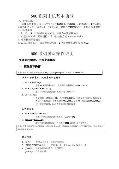
600系列主机基本功能一、型号说明:600系列主机有以下几个型号:TTX6084、TTX6164、TTX6224、TTX6324,分别为8进4出、16进4出、24进4出,键盘为TTX600VJ (一主机可带4键盘)二、功能说明1、8、16、24、32路视频输入可选,标准为4路视频输出2、C 型控制方式(同轴视控)或D 型控制方式(RS485方式)3、带有视频环通输出4、128路报警输入,带报警联动功能,1个报警继电器输出(50V A )600系列键盘操作说明变速摇杆键盘,支持变速操作一 .键盘基本操作选择一个摄象机、视频序列和监视器1. nn + [CAMERA]:选择nn 号摄象机在当前监视器上进行操作(nn=1—32);2. nn + [SEQUENCE RECALL];选择一个预先编程好的视频序列(nn=1—4);3. 选择监视器:扭动钥匙,键盘显示PR ,再按[CAMERA],可改变监视器号,根据需要选择几号监视器;(或者是按住[CAMERA]保持5S ,然后再按[CAMERA],可改变监视器号,根据需要选择几号监视器)选择预置位4. nn + [PRESET RECALL]:调用一个预先编程好的预置位;(nn=1—16)5. [PRESET RECALL]:瞬时功能6. 操作杆: 控制云台水平、垂直方向功能;7.[LENS FUNCTIONS ]: 光圈开、关,聚焦远、近,视角大、小;8.[HOME]: 使云台回到初始点,即预置位1;[WASH]: 开启喷水器,[AUX2]:使用直流云台时,会使其速度加倍。
开关控制功能键[LENS SLOW]、[AUTO IRIS]、[LAMPS]、[CAMARA ON/OFF]、[WIPE]、[AUX1]分别为镜头慢速,自动光圈,灯光,摄象机开关,雨刮器,辅助功能键(以上各功能要求设备具有相应的功能才能实现)。
[ALL ON]、[ALL OFF]全开和全关功能,例如:[ALL ON] [WIPE]就是将所有的雨刷器都打开。
PS6000数字化变电站自动化系统说明书V301D
国电南自PS6000+数字化变电站自动化系统产品简介3.01D版国电南京自动化股份有限公司GUODIAN NANJING AUTOMATION CO.,LTDPS6000+数字化变电站自动化系统产品简介3.01D版国电南京自动化股份有限公司2008年12月版本声明●本说明书适用于PS6000+数字化变电站系统整体介绍说明。
●本说明书包含数字化技术内容介绍、推荐方案介绍与数字化产品介绍。
●本说明书适用于PS6000+数字化变电站系统整体介绍与数字化变电站配置方案介绍。
产品说明书版本修改记录表* 技术支持电话:(025)83537220传真:(025)83537201* 本说明书可能会被修改,请注意核对实际产品与说明书是否相符* 国电南自技术部监制目录版本声明1 数字化变电站概述 (1)1.1背景 (1)1.2数字化变电站定义 (1)1.3数字化变电站特点 (1)1.4数字化变电站的优势 (2)2 PS 6000+数字化变电站自动化系统简介 (4)2.1系统特点 (4)2.2系统架构 (4)2.3PS6000+典型系统方案 (6)2.4设备简介 (11)2.5系统演示 (12)2.6PS6000+系统典型应用方案 (14)2.7PS6000+主要设备型号列表 (21)3 产品说明 (22)3.1PS6000+自动化系统(监控) (22)3.2PSX600U通信服务器 (25)3.3VSCL61850配置工具 (27)3.4PSL600U系列线路保护装置 (27)3.5PSL621U系列高压线路保护测控装置 (34)3.6PSL630U断路器保护装置 (38)3.7PSB681U母线保护装置 (42)3.8PST671U变压器保护装置 (46)3.9PSC641U电容器保护测控装置 (50)3.10PSL641U线路保护测控装置 (54)3.11PSL642U线路保护测控装置 (58)3.12PSP641U备用电源自投装置 (62)3.13PST642U变压器保护测控装置 (66)3.14PSR660U系列综合测控装置 (70)3.15PSIU600系列智能终端 (74)3.16PSW618智能工业以太网交换机 (78)1 数字化变电站概述1.1背景随着嵌入式系统及通信技术的飞速发展,目前基于32位微处理器和以太网通信的变电站自动化系统已被普遍采用。
技嘉600说明书
t600版權聲明手冊內所涵蓋的所有集嘉手機產品,包括手機本體、配件、軟體、文字、音樂與圖片,其所有權皆歸集嘉所有或由集嘉取得合法授權,並受著作權法、商標法、專利法等相關法律之保護。
未經集嘉同意之下,不得做任何翻拷或仿製。
若發生因上述行為而造成侵害集嘉權益之情事,行為人應負擔相應之法律責任。
技嘉集團 集嘉通訊股份有限公司t600歡迎使用擁有二百萬畫素的照相功能。
多元的PDA應用功能讓您在行動時,一手掌握資訊的動脈。
便利的Windows Direct Push讓您在外洽公也能以Wi-Fi 或GPRS 接收公司內部的電子郵件、查詢通訊錄,行動辦公不受限制。
您可以隨時隨地收看數位電視,走在資訊的尖端。
黑名單和背景混音保護您的重要機密和隱私,讓通話空間安全無虞。
個人化的來電插撥鈴聲、電話答錄功能提昇您的效率。
隨手機將配有原廠配件,包括應用程式安裝光碟、電池、耳機、旅充、觸控筆及USB資料傳輸線。
t600使用須知在您開始使用您的前,請詳讀下列重要訊息,若未詳讀下列訊息,可能會導致危險及觸犯法律問題。
--- 在您開始使用 之前,請先將電池完全充電。
--- 在充電過程中,請勿將電池從行動裝置中取出。
--- 插入SIM卡之前,請先確定您的行動裝置已關閉電源。
--- 請勿擅自拆裝您的行動裝置,若未經由授權人員自行拆裝,將有可能失去保固。
--- 在公共場所時,請遵守指示及規定使用您的行動裝置。
--- 在某些國家,當您要使用通話錄音功能時,您必須先告知對方,若未先告知對方,可能會觸犯當地法令。
注意:經型式認證合格之低功率射頻電機,非經許可,公司,商號或使用者均不得擅自變更頻率、加大功率或變更原設計之特性及功能。
低功率射頻電機之使用不得影嚮飛航安全及干擾合法通信;經發現有干擾現象時,應立即停用,並改善至無干擾時方得繼續使用。
前項合法通信,指依電信法規定作業之無線電通信。
低功率射頻電機須忍受合法通信或工業、科學及醫療用電波輻射性電機設備之干擾。
600系列说明书

600系列三相电力仪表(版本号:4.00)使用说明书(使用前请详细阅读此说明书)目录1、简述 (1)1.1 600的功能 (1)1.2 600功能描述 (1)1.3 600的特点 (1)2、安装、接线与配置 (2)2.1 尺寸与安装 (2)2.2 接线与配置 (3)3、界面显示说明 (5)3.1 显示模式下按键功能示意图 (5)3.2 编程模式下参数查询及修改按键功能示意图 (5)3.3 显示模式下功能显示灯指示说明 (6)4、操作说明 (6)4.1 循环显示说明 (6)4.2 键盘编程说明 (6)4.3 功能设置 (6)5、运输与贮藏 (7)6、保修期限及订货说明 (7)附表:常见故障排除 (8)1、简述1.1 600系列的功能600系列三相电力仪表是用于低压电力系统的智能化装置,该系列产品包括电流表、电压表、有功功率表、无功功率表、功率因数表、电度表等适合用户不同应用需求的仪表产品,该系列仪表可以完全替各种代指针式电力仪表,且精确度更好、性能更加稳定。
600系列三相电力仪表具有选配4路开关量输入、2路脉冲输出、RS485通讯接口,通讯协议为MODBUS通讯协议或其它指定通讯协议。
1.2 600系列功能描述1.2.2 通讯功能(扩展功能)600系列产品均可选配RS485通讯接口,通讯协议为MODBUS通讯协议或其它指定通讯协议。
可通过通讯口,可查询全部的测量监控信息。
面板带有带有LED指示灯,用于通讯收/发指示。
1.2.3 1~4路开关量输入功能(扩展功能)600系列产品均可选配1~4路开关量输入,为无源节点输入。
可在测量显示区查看开关量的状态。
1.2.4 模拟量输出功能(扩展功能)600系列部分产品可选配1~2路DC4~20mA,通过编程设置可将模拟量(DC 4-20mA)输出设置为与某一被测参数(定货时需指定)成比例的输出。
模拟量输出的最大负载为300Ω,可选择项为三相电流表的IA、IB、IC,三相电压表的UA、UB、UC。
IXYS CORPORATION XPTM 600V IGBT 产品说明书
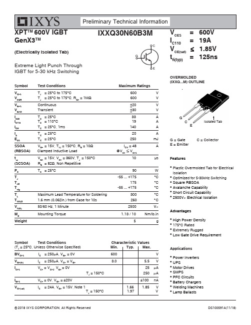
XPT TM 600V IGBT GenX3TMCES I C110= 19A V CE(sat) ≤ 1.85V t fi(typ)= 125nsExtreme Light Punch Through IGBT for 5-30 kHz SwitchingFeatures●Plastic Overmolded Tab for Electrical Isolation●Optimized for 5-30kHz Switching ●Square RBSOA●Avalanche Capability ●Short Circuit Capability ●2500V~ Electrical IsolationAdvantages●High Power Density ●175°C Rated●Extremely Rugged●Low Gate Drive RequirementApplications●Power Inverters ●UPS●Motor Drives ●SMPS●PFC Circuits ●Battery Chargers ●Welding Machines ●Lamp BallastsSymbol Test ConditionsMaximum Ratings V CES T J = 25°C to 175°C600V V CGR T J = 25°C to 175°C, R GE = 1M Ω 600V V GES Continuous ±20V V GEM Transient±30V I C25T C = 25°C 33A I C110T C = 110°C 19A I CM T C = 25°C, 1ms 140AI A T C = 25°C 20 A E AST C = 25°C 250 mJSSOA V GE = 15V, T VJ = 150°C, R G = 10Ω I CM = 48A(RBSOA) Clamped Inductive Load @V CE ≤ V CES t scV GE = 15V, V CE = 360V, T J = 150°C 10 μs (SCSOA)R G = 82Ω, Non Repetitive P C T C = 25°C90W T J -55 ... +175°C T JM 175°C T stg -55 ... +175°C T LMaximum Lead Temperature for Soldering 300°C T SOLD 1.6 mm (0.062in.) from Case for 10s 260°CV ISOL 50/60 Hz, 1 Minute 2500 V ~M d Mounting Torque1.13 / 10 Nm/lb.inWeight5g(Electrically Isolated Tab)OVERMOLDED(IXXQ...M) OUTLINEG = Gate C = CollectorE = EmitterG CESymbol Test Conditions Characteristic Values (T J = 25︒C, Unless Otherwise Specified) Min. Typ. Max.BV CES I C = 250μA, V GE = 0V 600 VV GE(th)I C = 250μA, V CE = V GE3.05.5VI CES V CE = V CES , V GE = 0V25μA T J = 150︒C 250 μA I GES V CE = 0V, V GE = ±20V±100 nAV CE(sat)I C = 24A, V GE = 15V, Note 11.66 1.85 V T J = 150︒C1.97 VIXYS Reserves the Right to Change Limits, Test Conditions, and Dimensions.Notes:1. Pulse test, t ≤ 300μs, duty cycle, d ≤ 2%.2. Switching times & energy losses may increase for higher V CE (clamp), T J or R G .Symbol Test Conditions (T J = 25°C Unless Otherwise Specified)fs I C = 24A, V CE = 10V, Note 1 8 14C ie sC oes V CE = 25V, V GE C resQ g(on)Q ge I C = 24A, V GE = 15V, V Q gc d(on)OVERMOLDED OUTLINE1 = Gate2 = Collector3 = EmitterPRELIMINARY TECHNICAL INFORMATIONThe product presented herein is under development. The Technical Specifications offered are derived from a subjective evaluation of the design, based upon prior knowledge and experi-ence, and constitute a "considered reflection" of the anticipated result. IXYS reserves the right to change limits, test conditions, and dimensions without notice.Fig. 1. Output Characteristics @ T 1520253035404550I C - A m p e r e sFig. 7. Transconductance810121416182022g f s - S i e m e n sFig. 13. Inductive Switching Energy Loss vs.Gate Resistance1.01.21.41.61.82.0E o f f - M i l l i J o u l e sE off E on T J = 150oC , V GE = 15V V CE = 400VIXYS Reserves the Right to Change Limits, Test Conditions, and Dimensions.Fig. 19. Inductive Turn-on Switching Times vs.Gate Resistance6080100120140160 r i - N a n o s e c o n d st r i t d(on)T J = 150oC, V GE = 15V V CE = 400VI C = 48A。
科力德 SPS6000X 系列宽范围可编程直流开关电源 数据手册说明书
数据手册CN_01A产品综述SPS6225X是一款可提供宽范围单路输出,限定功率的可编程直流开关电源。
该机型具备200V额定输出电压,25A电流,1500W的最大输出功率。
用户可并联同型号电源5台来扩展输出功率,满足更大电流需求的应用场景。
SPS6000X系列可编程直流开关电源配备了3.12英寸高亮度OLED显示屏,拥有友好的人机交互界面和优异的性能指标,设置最小分辨率为10mV/10mA。
输出电压,电流上升速度可调,具有恒压,恒流两种输出模式,也支持List序列编程模式,同时具备过压,过流,过功率,过温全方位保护,可靠性高等特点。
标配LAN/USB通讯接口,模拟控制接口,产品可通过Web网页进行远程控制。
可广泛应用于多种要求苛刻的测试场所,例如电源行业,实验室通用测试,LED照明行业,汽车电子等多种领域。
特性与优点额定电压:200V;额定电流:25A;额定输出功率:1500W定功率输出,满足电压,电流宽范围输出,高效率开关型电源CV,CC优先模式选择,更好的保护待测物快速输出响应时间<2.5ms电压,电流上升/下降速率可调设置,回读分辨率10 mV,10mA自带泄放电路,关机后可将输出电容中的电量泄放置安全电压以下支持远端电压补偿Sense功能支持本地List功能50步编辑,USB导入List序列文件外部模拟量电压控制,电压,电流监控输出过电压、过电流、限功率、过温保护,安全可靠3.12英寸OLED高亮度显示屏,可拥有170度宽广的观察视角配置USB,LAN标准通信接口,选配USB-GPIB模块拥有44mm高度(1U)标准机架尺寸的外形内嵌了Web Server,无需安装驱动软件和上位机软件,通过浏览器即可对仪器进行远程控制1 SPS6000X系列宽范围可编程直流开关电源数据手册SPS6000X 系列宽范围可编程直流开关电源数据手册 2设计特色宽范围输出在限定输出功率条件下,电压电流量程自动切换,在一台电源上实现多种电压和电流的组合输出。
PHILIPS CTX600BL手机 说明书

PhilipsXeniumX600CTX600BLK恆久經典的魅力快速的生活節奏,有時會令人感到疲累,您需要一部充滿動景、活力澎湃的手機來讓您的生活重新振作起來。
飛利浦 Xenium X600 擁有超長電池壽命及多媒體應用程式,讓您充滿自信地迎接每天的挑戰。
保持開啟和連線狀態•長達 1 個月的待機時間•最多 8.5 小時的通話時間盡情享受多媒體體驗•享受藍牙立體聲音樂•以 MPEG4 與 H263 格式擷取與播放影像•MicroSD 記憶卡插槽可增加記憶體或資料的儲存容量•2 百萬像素相機為您留住美好一刻保持連線•增強的數據速率帶來 GSM 革命*精于心 ?于形產品特點長達 1 個月的待機時間單次充電可使用的連續待機時間高達 1 個月最多 8.5 小時的通話時間本手機單次充電即可通話達 8.5 小時。
藍牙立體聲音樂您的 Philips 手機支援 A2DP 藍牙設定檔。
它可讓您無線享受喜愛的音調,而且還可以透過藍牙耳筒,聆聽高質量的立體聲音樂。
邊沿EDGE 的數據容量是 GPRS 的 3 倍,讓您可以享受高速的互聯網及 WAP 存取、內容下載、收發電郵以及快速發送/接收 MMS 訊息。
向網絡運營商簽用 GPRS 服務,以及在啟用了 EDGE 手機上設定 GPRS 設定檔。
2 百萬像素相機用 2 百萬像素的相機將您生活中美好一刻拍攝成清晰的相片,讓您在往後的日子細意回味。
只需輕按快門,即可拍攝出逼真、色彩豐富的相片。
MMS出版日期 2009-11-17版本: 1.0.212 NC: 8670 000 49726 EAN: 87 12581 46517 9© 2009 Koninklijke Philips Electronics N.V.版權所有。
規格若有變更恕不另行通知。
商標為 Koninklijke Philips Electronics N.V. 或其個別所有者的財產。
規格尺寸•天線: 整合式•款式: 摺機•手機色彩: 幻影黑•手機尺寸: 96.8 x 52 x 16.5mm•手機重量: 110g圖像/顯示•主熒幕色彩: 262K•主熒幕解像度: 176x220 像素•多行文字: 6•主熒幕技術: TFT•次熒幕色彩: B/W•次熒幕解像度: 64x64 像素•次熒幕技術: OLED•熒幕對角尺寸: 2.2 吋靜態圖像擷取•相機: 整合式•圖像感應器類型: CMOS•預覽畫面速率: 25 格/秒•圖像檔案格式: JPEG•圖像模式: 自動計時模式, 連續, 多重拍攝, 夜間模式•圖像解像度: VGA (640x480), 176x220,768x1024, SXGA (1280x1024), 2M (1600x1200)•敏感度: 最少 1 明亮度•特殊效果預覽模式: 褐色, 藍光效應, 黑白•畫面質素: 普通, 細緻, 超細緻靜態畫面播放•圖像壓縮格式: BMP, JPEG, WBMP•幻燈片展示: 是音效•鈴聲: MP3 鈴聲, 64 和弦鈴聲, 語音記事鈴聲聲音擷取•語音錄音: 是, AMR播放聲音•音效支援模式: AMR, Midi, MP3, AAC, WAV, AAC+, WMA錄音•錄製你自己的聲音: 是影像擷取•畫面速率: 15 fps•圖像感應器解像度: 2M 像素•圖像感應器類型: CMOS•影像格式: H.263, MPEG4•影像解像度: QCIF影像播放•壓縮格式: MPEG4, H.263•解像度 (pxl): 176x144影片錄製•壓縮格式: H.263, MPEG4儲存媒體•內置記憶體容量: 256 Mb Flash + 64 Mb RAM •記憶卡類型: Micro Secure Digital (SD)•記憶體管理: 記憶體狀態, 動態記憶分佈•使用者記憶體: 10 MB•最大記憶卡容量: 2 GB網絡功能•GPRS (Rx+Tx): Class 10 (4+2), Class B•GSM 頻: 900, 1800, 1900 MHz•訊息: 長串 SMS (長 SMS ), 電子郵件, MMS (多媒體訊息服務), SMS CB (手機廣播), SMS (短訊服務), SMS 多人接收, 預定 SMS, WAP OTA配置•服務: OTA 配置 (WAP,MMS), SIM 工作套件 /Release 99, WAP 2.0•語音 Codec: FR/EFR/AMR/HR•邊沿: 是便利•按鈕與控制器: 4 向導航鍵並輸入, 軟鍵•來電管理: 來電轉接, 來電插撥, 通話時間, 來電等候, 來電顯示, 會議電話, 緊急呼叫, 咪高風靜音, 未接來電, 多方通話, 已接來電, 防火墻•時鐘/版本: 數碼, 國際時鐘•輕鬆導覽: 自動彈蓋•方便易用: 免提模式, 熱鍵, 飛行模式, 快捷鍵,震動警示•遊戲與應用程式: 鬧鈴, 計算機, 日曆, 歐元換算器, Java MIDP 2.0, 農曆, 秒錶, 倒數計時器,中國節日提示, 國際貨幣轉換器, 女仕日曆, 價格比較表, 我的卡片, 折扣管理程式, MSN,Sudoku 遊戲•可用語言:T9 輸入: 簡體中文, 繁體中文, 英文, 法文, 俄文, 土耳其文, T9 阿拉伯文•可用語言:UI: 簡體中文, 繁體中文, 英文, 印尼文, 泰文, 越南文•個人資料管理: 日光節約, 時區, 智慧電話簿,Vcard 交換, 國際時鐘•個人化/自訂化: 可下載圖像, 可下載鈴聲, 來電彩色影像顯示, 牆紙, 鈴聲, 可下載動畫 GIF,可下載 Java 應用程式•內置遊戲: 3•語言辨識: 通話錄音, 長語音記事, 語音記事•計時器: 是•振動器: 是•音量控制: 是連接•耳筒: 經由迷你 USB 連接器•Modem能力: CSD (語音,數據), GPRS, SMS•同步化 PC 日誌管理: Lotus Notes, MS Outlook•無線連接: 藍芽•藍芽: 是•藍芽規格: A2DP, 免提, 耳筒, Object Push 設定檔配件•標準套件內含: 電池, CD-Rom (手機工具), 充電器, 手機, 全球保修, 立體耳筒, 用戶手冊,USB 數據線功率•電池容量: 1100 mAh•省電控制: 自動開/關•電池類型: 鋰離子•充電時間: 約 2.5 hr•待機時間: 最久達 1 個月•通話時間: 長達 8.5 小時綠色環保規格•無鉛焊接?品: 是。
Philips 600 Series 无线键鼠组合说明书

Philips 600 SeriesWireless keyboard-mouse combo3 buttonsWirelessCompact DesignSPT6602BDesigned for what you doDesigned for your productive life, the 600 series keyboard-mouse combo offers a well-designed ergonomic keyboard and mouse for reliable all-day use. The plug it and forget it wireless, cleans up your desktop for your best work.Wireless simplicity•Strong 2.4GHz plug it and forget it wireless for simplicity Keyboard designed for ultimate productivity •Familiar layout for easy typing•Low-profile keys for comfortable quiet typing •Thin profile design looks great on your desk Comfortable accurate control•High definition optical tracking for smooth control •Comfortable ergonomic mouse design feels great •Ambidextrous shape feels good in right or left hand Philips reliability•Keys last millions of keystrokes for durability•Water resistant design for cleaning and occasional spillsHighlightsWireless connectionStrong 2.4GHz plug it and forget it wireless for simplicityFamiliar keyboard layout Familiar layout for easy typingQuiet-typingLow-profile keys for comfortable quiet typingThin profile design Thin profile design looks great on your deskSmooth optical trackingHigh definition optical tracking for smooth controlComfortable ergonomic designComfortable ergonomic mouse design feels greatAmbidextrous mouse designAmbidextrous shape feels good in right or left handKeystrokes for durabilityKeys last millions of keystrokes for durabilityWater resistant keysLife can be messy. With this water resistant keyboard, the occasional spill or spray off is noproblem. These keyboards are built to last.Issue date 2021-12-09 Version: 1.0.112 NC: 8670 001 57129 EAN: 87 12581 75507 2© 2021 Koninklijke Philips N.V.All Rights reserved.Specifications are subject to change without notice. Trademarks are the property of Koninklijke Philips N.V. or their respective owners.SpecificationsTechnical specifications•Product Type: Wireless keyboard-mouse combo •Connectivity: 2.4GHz Wireless Connection, 10 Meters effective wireless connection distance •Front Panel Material-Keyboard: Plastics front-panel •Keys: 104 Keys•Optical Sensor Precision-Mouse: 1000 dpi mouse •Handed Type: Left and right-handed mouse Physical Dimensions•Dimensions (LxWxH): Mouse: 112.92 x 60.63 x 37.4 (mm), Keyboard: 432.7 x 124.8 x 26.24 (mm)•Weight: Mouse: 97 ± 5 (g), Keyboard: 450 ± 5 (g) OS/System Requirements•System Requirements: Microsoft Windows 2000, ME, XP, Vista and above, Linux, IOS。
Omega PX600 和 PX610 系列压力传感器说明书
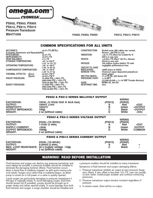
PX602,PX603,PX605PX612,PX613,PX615Pressure Transducer M947/1009PX602,PX603,PX605PX612,PX613,PX615COMMON SPECIFICATIONS FOR ALL UNITSACCURACY:±0.4%FS (BFSL)(Linearity,Hysteresis and Repeatability)HYSTERESIS:±0.2%FS REPEATABILITY:±0.07%FS ZERO BALANCE:±1%FS STORAGE TEMPERATURE:–65°to 250°F(–53°to 121°C)OPERATING TEMPERATURE:–20°to 180°F(–28°to 82°C)COMPENSATED TEMPERATURE:–20°to 160°F(–28°to 71°C)THERMAL EFFECTS:(Zero)±0.04%FS/°F(Span)±0.04%FS/°FPROOF PRESSURE:15-2000PSI =200%FS;3000-5000PSI =150%FS 7500-20,000PSI =120%FSBURST PRESSURE:15-2000PSI =800%FS;3000-5000PSI =300%FS 7500-20,000PSI =150%FSCONSTRUCTION:Sealed units (All cables are vented.Sensor >300PSI is not)VIBRATION:<±0.1%FS effect for 0-2000Hz @20G’s in any axisSHOCK:<±0.05%FS effect 100G’s,20msec shock in any axisFATIGUE:100million cycles 20/80%FS with negligible performance lossCIRCUIT TO CASE INSULATION:100M ohms at 50VdcSENSOR TYPE:Chemical vapor deposited polysilicon strain gagesWETTED PARTS:17-4PH SS,300Series SS PRESSURE PORT:1⁄4-18NPT(15,000-20,000=9⁄16-18UNF Female Aminco)CASE:NEMA 4X,304SS RESPONSE TIME:5msPX602&PX612SERIES MILLIVOLT OUTPUTWIRING EXCITATION:10Vdc,(5-10Vdc limit @6mA max)(PX612)(PX602)OUTPUT:100mV ±1mV A Red +EXC SENSITIVITY:10mV/V B Green +OUTPUT OUTPUT IMPEDANCE:100ΩC Black –OUTPUT WEIGHT:2 oz (without cable)DWhite –EXCPX603& PX613 SERIES VOLTAGE OUTPUTWIRING EXCITATION:24Vdc, (10-36Vdc)(PX613)(PX603)OUTPUT:1-5Vdc (3 wire)A Red +EXC SUPPLY CURRENT:<3mA B Green OUTPUT OUTPUT IMPEDANCE:1000ΩDWhiteCOMMONWEIGHT:2 oz (without cable)PX605& PX615 SERIES CURRENT OUTPUTWIRING EXCITATION:24Vdc, (10-36Vdc)(PX615)(PX605)OUTPUT:4-20mA (2 wire)A Red +MAX. LOOP RESISTANCE:50 x (supply voltage –10)ΩCBlack–WEIGHT:2 oz (without cable)WARNING! Fluid hammer and surges can destroy any pressure transducer and must always be avoided. A pressure snubber should be installed to eliminate the damaging hammer effects. Fluid hammer occurs when a liquid flow is suddenly stopped, as with quick closing sole-noid valves. Surges occur when flow is suddenly begun, as when pump is turned on to full power or a valve is quickly opened.Liquid surges are particularly damaging to pressure transducers if the pipe is originally empty. T o avoid damaging surges, fluid lines should remain full (if possible), pumps should be brought up topower slowly and valves opened slowly. To avoid damage from both fluid hammer and surges, a surge chamber should be installed anda pressure snubber should be installed on every transducer.Symptoms of fluid hammer and surge’s damaging effects:1.Pressure transducer exhibits an output at zero pressure (large zero offset). If zero offset is less than 10% FS, user can usually re-zero meter, install proper snubber and continue monitoring pressures.2. Pressure transducer output remains constant regardless of pressure.3. In severe cases, there will be no output.HANDLINGThis instrument is susceptible to damage when exposed to static elec-trical charges. T o avoid damage to the sensor observe the following:• Ground the transducer body before making any electrical c onnections.• When disconnecting, remove ground connection last.Note:If supplied, the braided shield in the cable is not connected tothe transducer’s body and is not a suitable ground.MOUNTINGAlthough the units can withstand some vibration, it is always good practice to mount the sensor where there is minimum vibration. Use T eflon ®tape on NPT threads and install the wrench on hex flats. DO NOT tighten by using a pipe wrench on the housing.(T eflon is a registered trademark of E. I. Dupont de Nemours)CALIBRATIONAll models are tested to meet or exceed the published specifica-tions. The calibration and testing was performed using instrumenta-tion and standards that are traceable to the U.S. National Institute of Standards and T echnology (NIST). We further certify that our cali-bration systems complies with MIL-STD-45662.Each sensor comes calibrated and does not require recalibration.The zero and span pots are accessible through the top of the case.Loosen the four screws and separate the top carefully. The zero pot is marked with a white dot. Some models have the span pot on the side of the pull out board. Be careful of static charges when touching the board (span pot will be on the opposite side from the zero pot).WARRANTYOMEGA warrants this unit to be free of defects in materials and workmanship and to give satisfactory service for a period of 13 months from date of purchase. OMEGA’s Warranty adds an additional one (1)month grace period to the normal one (1) year product warranty to cover handling and shipping time. This ensures that our customers receive maximum coverage on each product. If the unit malfunctions, it must be returned to the factory for evaluation. Our Customer Service Department will issue an Authorized Return (AR) number immediately upon phone or written request. Upon examination by OMEGA, if the unit is found to be defective, it will be repaired or replaced at no charge. However, this WARRANTY is VOID if the unit shows evidence of having been tampered with or shows evidence of being damaged as a result of excessive corrosion; or current, heat, moisture or vibration; improper specification;misapplication; misuse or other operating conditions outside of OMEGA’s control. Components which wear or are damaged by misuse are not warranted. T hese include contact points, fuses, and triacs.We are glad to offer suggestions on the use of our various products. Nevertheless, OMEGA warrants only that the parts manufactured by it will be as specified and free of defects.OMEGA MAKES NO OTHER WARRANTIES OR REPRESENT A TIONS OF ANY KIND WHA TSOEVER,EXPRESS OR IMPLIED, EXCEPT THA T OF TITLE, AND ALL IMPLIED WARRANTIES INCLUDING ANY WARRANTY OF MERCHANT ABILITY AND FITNESS FOR A PARTICULAR PURPOSE ARE HEREBYD ISCLAIMED. LIMIT A TION OF LIABILITY : The remedies of buyer set forth herein are exclusive, and the total liabili-ty of OMEGA with respect to this order, whether based on contract, warranty, negligence, indem-nification, strict liability or otherwise, shall not exceed the purchase price of the component upon which liability is based. In no event shall OMEGA be liable for consequential, incidental or special damages.Every precaution for accuracy has been taken in the preparation of this manual, however, OMEGA ENGINEERING, INC. neither assumes responsibility for any omissions or errors that may appear nor assume liability for any damages that result from the use of the products in accordance with the information contained in the manual.OMEGA’s policy is to make running changes, not model changes, whenever an improvement is possible.This affords our customers the latest in technology and engineering.OMEGA is a registered trademark of OMEGA ENGINEERING, INC.© Copyright 1992 OMEGA ENGINEERING, INC. All rights reserved including illustrations. Nothing in this manual may be reproduced in any manner, either wholly or in part for any purpose whatsoever without written permission from OMEGA ENGINEERING, INC. 2M807Servicing USA and Canada: Call OMEGA Toll FreeOMEGA Engineering, Inc.One Omega Drive, Box 4047Stamford, CT 06907-0047 U.S.A.Headquarters: (203) 359-1660Sales: 1-800-826-6342 / 1800-TC-OMEGACustomer Service: 1-800-622-2378 / 1-800-622-BEST Engineering: 1-800-872-9436 / 1-800-USA-WHENFAX: (203) 359-7700 TELEX: 996404 EASYLINK: 62968934 CABLE: OMEGAServicing Europe: United Kingdom Sales and Distribution centerOMEGA Technologies Ltd.P .O. Box 1, Broughton Astley, Leicestershire LE9 6XR, EnglandTelephone: (0455) 285520 FAX: (0455) 283912RETURN REQUESTS /INQUIRIESDirect all warranty and repair requests/inquiries to OMEGA’s Customer Service Department. Call toll free in the U.S. and Canada: 1-800-622-2378, Fax: 203-359-7811;International: 203-359-1660; Fax: 203-359-7807.BEFORE RETURNING ANY PRODUCT(S) TO OMEGA, YOU MUST OBTAIN AN AUTHOR-IZED RETURN (AR)NUMBER FROM OUR CUSTOMER SERVICE DEPARTMENT (IN ORDER TO AVOID PROCESSING DELAYS). The assigned AR number should then be marked on the outside of the return package and on any correspondence.Please have the following information available BEFORE contacting OMEGA:1. P .O. number under which the product was purchased.2. Model and serial number of the product, and3. Repair instructions and/or specific problems you are having with the product.PX602, PX603, PX605PX612, PX613, PX615DIMENSIONSWIRINGPX602, PX612PX603, PX613PX605, PX615+––+POWER SUPPLY(–EXC)(+EXC)(+SIG)(–SIG)METERTRANSDUCER (PX602, PX612)RED WHITEBLACK GREEN DA BC++––POWER SUPPLY(COMMON)(+ EXC)(+ OUTPUT)METERTRANSDUCER (PX603, PX613)WHITE RED GREEN A DBPOWER SUPPLY。
Poly CCX 600 商业媒体电话说明书

POLY CCX 600A larger screen can make all the difference. The Poly CCX 600 Business Media Phone boasts a 7” screen — perfect for managers and executives, and anybody who needs more room to do their thing. Count on legendary audio quality, Poly HD Voice, and Poly Acoustic Clarity. Poly Acoustic Fence technologywipes out distracting background noise. So noisy places like open offices don’t get in the way of meaningful and productive discussions. Conversations stay on track thanks to full duplex speakerphone operation with world-class echo cancellation.The interface is simple and intuitive to use with one-touch-access to yourcontacts and meetings. And the phone is fast and responsive, designed with the latest powerful chipsets. Robust provisioning and management enable efficient telephony deployment and support. And it’s easy to install anywhere — Wi-Fi is included. Now let’s talk options. Productivity starts here.• Model choices supporting Open SIP or native Microsoft T eams.• Color touchscreen operation with 7” multi-touch LCD display.• Hear every nuance with Poly HD Voice and Poly Acoustic Clarity.• Eliminate distracting background noise with Poly Acoustic Fence technology.• Full duplex speakerphone operation with world-class echo cancellation and Poly NoiseBlockAI technology. • Powerful chipsets to support next-generation features.• Easy to install anywhere with integrated Wi-Fi.• Headset options to suit any style (Bluetooth ®, USB, RJ9).• Make video calls with optional EagleEye Mini USB camera (Open SIP CCX 600 only).SIMPLE.INTUITIVE.POWERFUL.BENEFITS• Conversations stay on track. Hear every nuance with industry-leading sound quality featuring Poly HD Voice.• Eliminate distracting background noise at the source with Poly Acoustic Fence and NoiseBlockAI technologies.• Contacts and meetings are easily accessible, one tap away on a color touchscreen.• Easy for IT to manage with robust provisioning and management of telephony deployment and support.• Multiple headset options are available to suit any working style — in additionto the traditional handset.DATA SHEETSPECIFICATIONSUSER INTERFACE FEATURES• Gesture-based, multitouch-capable touchscreen• 7” color LCD (1024 x 600 pixel)• 16:9 aspect ratio Screensaver• On-screen virtual keyboard• Voicemail support• Adjustable base height• One USB type-A port (2.0 compliant) for media and storage applications• One USB Type-C port (2.0 compliant) for media and storage applications• Integrated Bluetooth 4.2• Integrated Wi-Fi• Unicode UTF-8 character support• Adjustable font size selection (regular, medium, large)• Normal and dark mode• Multilingual user interface including Chinese, Danish, Dutch, English (Canada/ US/UK), French, German, Italian, Japanese, Korean, Norwegian, Polish, Portuguese, Russian, Slovenian, Spanish, and SwedishAUDIO FEATURES• Poly HD Voice technology delivers lifelike voice quality for eachaudio path: handset, hands-free speakerphone, and optional headset • Poly Acoustic Clarity technology providing full duplex conversations, acoustic echo cancellation, and background noise suppression• Poly Acoustic Fence eliminates background noise when using a handset or wired headset• Poly NoiseBlockAI technology removes most background noise when using the speakerphone even while you are talking • TIA-920 wideband audio, type 1compliant (IEEE 1329 full duplex)• Frequency response—100 Hz–20 kHzfor handset, optional headset, andhandsfree speakerphone modes• Codecs: G.711 (A-law and μ-law),G.729AB, G.722 (HD Voice), G.722.1iLBC• Individual volume settings with visualfeedback for each audio path• Voice activity detection• Comfort noise generation• DTMF tone generation (RFC 2833and in-band)• Low-delay audio packet transmission• Adaptive jitter buffers• Packet loss concealment• OPUS supportHEADSET AND HANDSET COMPATIBILITY• Dedicated RJ-9 headset port• Hearing aid compatibility to ITU-T P.370and TIA 504A standards• Compliant with ADA Section 508Subpart B 1194.23 (all)• Hearing aid compatible (HAC) handsetfor magnetic coupling to hearing aids• Compatible with commercially-availableTTY adapter equipment• USB headset support• Bluetooth headset supportNETWORK AND PROVISIONING• SIP protocol support• SDP• IETF SIP (RFC 3261 and companionRFCs)• Two-port gigabit Ethernet switch10/100/1000 Base-TX across LANand PC ports• Wi-Fi network connectivity–2.4-2.4835GHz (802.11b, 802.11g, 802.11n HT-20)-5.15-5.825 GHz (802.11a, 802.11n,HT-20, 802.11n HT-40)• Conforms to IEEE802.3-2005 (Clause 40)for physical media attachment• Conforms to IEEE802.3-2002 (Clause 28)for link partner auto-negotiation• Manual or dynamic host configurationprotocol (DHCP) network setup• Time and date synchronization usingSNTP• FTP/TFTP/HTTP/HTTPS server-based central provisioning for massdeployments• Provisioning and call server redundancysupported1• QoS Support—IEEE 802.1p/Q tagging(VLAN), Layer 3 TOS, and DHCP• VLAN—CDP, DHCP VLAN discovery,LLDP-MED for VLAN discovery -Network address translation support forstatic configuration and “keep-alive”• SIP signaling• RTCP and RTP support• Event logging• Syslog• Hardware diagnostics• Status and statistics reporting• IPv4 and IPv6• TCP• UDP• DNS-SRVSECURITY• 802.1X authentication and EAPOL• SRTP media encryption using AES-256• Encrypted configuration files• Digest authentication• Password loginDATA SHEETDATA SHEET©2023 Poly. All trademarks are the property of their respective owners. The Bluetooth trademark is owned by Bluetooth SIG, Inc. and any use of the mark by Poly is under license. 3.23 615324LEARN MOREFor more information on CCX 600 visit /ccx• Support for URL syntax with password for boot server address • HTTPS secure provisioning• Support for signed software executables • Wi-Fi encryption: WEP, WPA-Personal, WPA2-Personal, WPA2-Enterprise with 802.1X (EAP-TLS, PEAP-MSCHAPv2)POWER• Built-in auto sensing IEEE 802.3at Power over Ethernet (Class 4) 25 W (Max)• External universal AC/DC adapter (optional),***********(25W)REGULATORY APPROVALS • Argentina ENACOM • Australia RCM • Brazil ANATEL• Canada ICES and NRTLC • China SRRC • China RoHS 2.0• EEA CE Mark• Eurasian Customs Union EAC • India WPC • Indonesia SDPPI • Israel MOC • Japan MIC & VCCI • Malaysia SIRIM• Mexico IFETEL and NYCE • NZ T elepermit • Saudi Arabia CITC • Singapore IMDA • South Africa ICASA • South Korea KC • Taiwan NCC • UAE TRA• USA FCC and NRTLRADIO• USA–FCC Part 15.247 & FCC Part 15.407• Canada–RSS 247 Issue 2• EU–ETSI EN 300 328 & ETSI EN 301 893• Japan–Article 2.1 Item 19-2 and 19-3• Australia–AS/NZ4268SAFETY • UL 62368-1• CAN/CSA C22.2 No. 62368-1-14 • EN 62368-1• IEC 60950-1 and IEC 62368-1• AS/NZS 62368-1EMC• FCC Part 15 Class B • ICES-003 Class B • EN 55032 Class B • EN 55024• EN 301 489-1 and EN 301 489-3 and EN 301 489-17• CISPR32 Class B • VCCI Class BOPERATING CONDITIONS• T emperature: 0 to 40 °C (+32 to 104 °F)• Relative humidity: 5% to 95%, noncondensing STORAGE TEMPERATURE • -40 to +70 °C (-40 to +160 °F)POLY CCX 600 BUSINESS MEDIA PHONE COMES WITH • Console• Handset with handset cord • Network (LAN) cable—CAT-5E • Desk stand • Setup sheetPART NUMBERS• 2200-49780-025 CCX 600 Business Media Phone. Open SIP. PoE. Ships without power supply • 2200-49780-019 CCX 600 Business Media Phone. Microsoft T eams. PoE. Ships without power supply • 2200-49743-001 CCX 600 wall mount kit • 7200-49734-001 EagleEye Mini Camera with mounting kit for CCX 600 (Open SIP)SIZE• 26.3 cm x 21.7 cm x 6.0 cm WxHxD (10.4 in x 8.5 in x 2.4 in WxHxD)WEIGHT• 1.97 kg (4.34 lbs) MASTER CARTON QUANTITY • Five (5) WARRANTY • One (1) year1 Planned localization 2Planned compliance。
PS6000远动装置培训手册
PS6000远动装置运行及维护手册概述:国电南自PS6000系统远动服务器有3个型号,PSX600、PSX610、PSX600U 分别为三个时期的产品,主要完成变电站与远方调度主站的数据通讯,PSX 600通信服务器2000年随PS 6000系统一起推出,成熟稳定。
PSX 610通信服务器2004年鉴定,PSX 600的升级换代产品。
PSX600U通信服务器2007年鉴定,PSX 610的升级换代产品。
以上3种装置最多支持与10个主站通讯,即10独立远传区,支持RS232/RS4845/RS422通道,模拟通道,以太网通道。
除CPU和电源插件外,装置中其他插件通用。
通用插件只在PSX600装置中介绍。
PSX600U-CPU插件可以直接替换PSX600-CPU插件。
下面分别对3种远动服务器装置及通道切换装置进行介绍。
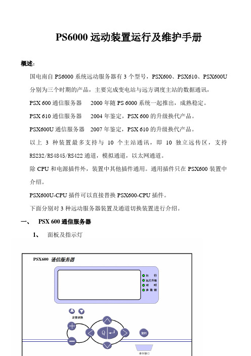
一、PSX 600通信服务器1、面板及指示灯PSX6001) 运行:正常以大约每秒一次的频率交替明灭,如果长亮或者长灭都说明程序没有正确运行,有可能是存储器等关键部件有了故障,建议更换CPU插件。
2) 远方升级:正常运行时不亮,当装置背后的CPU模式开关打到远方升级模式时此灯亮。
此指示灯亮表明屏蔽了所有正常功能,进入了特殊的程序升级工作状态。
程序升级完成后需要将模式开关拨回,此灯灭掉又回到正常工作状态。
3) 对时:当装置向站内网进行时钟校对时此灯短时间亮一下。
4) 参数错:正常运行时不亮,如果装置的装置发生可自检的程序错误或者检测到已下载的参数校验和出错时,该灯亮。
程序错与参数错所不同的是前者运行灯不亮,而参数出错时运行灯依然正常闪烁。
2、PSX600装置CPU工作模式设置在CPU插件上有一个注明“模式设置”的 4位DIP小开关,通过它可以设置装置的基本工作模式。
自上而下各位的功能如下:第1位:串行口程序升级模式选择。
打在“OFF”是正常工作模式,如果需要通过面板上的串行口进行程序升级,需要先将此开关打向“ON”,此时可以见到远方升级灯亮、运行灯正常闪烁,便可以在远方(通过拨号Modem)或者当地(直接用RS-232直通串口线与面板串行口连接)的PC机上运行PSView for PSX软件,进行程序的在线升级。
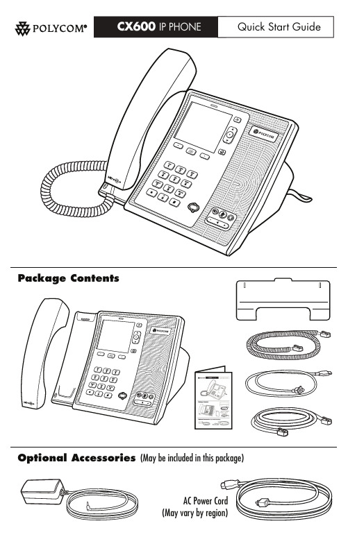
CX600 IP电话说明书
Package ContentsOptional Accessories (May be included in this package)Quick Start GuideAC Power Cord(May vary by region)FeaturesSoft key Volume Up/DownKeypad Speakerphone key LCD Display Menu keyUC Presence Indicator Microphone HookswitchReversible tab (For wallmount installation)Back keySoft key Home key Navigation keys(Up, Down, Select)Headset keyMute keySpeaker Security LockHandset cord jackLeft Side ViewSetupConnect the Ethernet cable as shown above. Connect the AC power supply as shown above, if not powered via the Ethernet cable. Follow the instructions provided on the LCD display to sign in, configure and use the phone.For more information, go to /support/cx600, or contact your system administrator.System RequirementsThe following are the minimum software and hardware requirements:• Ethernet connection• Access to AC power or Power Over Ethernet (PoE)• Network access to Microsoft® Lync™ Server 2010 or greaterIf a "Better Together" USB connection to a PC will be used, the PC must be equipped with Microsoft Lync 2010 or greater, and have a spare USB port.Connect Cables and StandUSB Cable (If used with a PC)Passthrough Ethernet connection to PC (Optional) (Extra cable not included)AC Power connection (Optional)Use if Power over Ethernet (PoE) is unavailablefully inserted into one of the slots on the NOTE: To ensure adequate support, the stand back of the phone.Type A USB Port (For future use)Polycom, Inc. 6001America Center Dr, San Jose, CA 95164 USAEnd User License, Warranty, and Safety Notices1725-15993-001 Rev. EThe software included in this Product (including, without limitation, firmware and all updated thereto, including any software that may be downloaded electronically via the internet or otherwise (the “Software”) is licensed, not sold. Customer shall not reverse compile, disassemble, or otherwise reverse engineer, embed with any other software product, or modify in any manner with respect thereto, the software in whole or in part.LIMITED WARRANTY. Polycom warrants to the end user (“Customer”) that this product will be free from defects in workmanship and materials, under normal use and service, Polycom’s sole obligation under this express warranty shall be, at Polycom’s option and expense, to repair the defective product or part, deliver to Customer an equivalent product or part to replace the defective item, or if neither of the two foregoing options are reasonably available, Polycom may, in its sole discretion, refund to Customer the purchase price paid for the defective product. All products that are replaced will become the property of Polycom. Replacement products or parts may be new or reconditioned. Polycom warrants any replaced or repaired product or part for ninety (90) days from Products returned to Polycom must be sent prepaid and packaged appropriately for safe shipment, and it is recommended that they be insured or sent by a method that provides for tracking of the package. Responsibility for loss or damage does not transfer to Polycom until the returned item is received by Polycom. The repaired or replaced item will be shipped to Customer, at Polycom’s expense, not later than thirty (30) days after Polycom receives the defective product, and Polycom will retain risk of loss or damage EXCLUSIONS. Polycom will not be liable under this limited warranty if its testing and examination disclose that the alleged defect or malfunction in the product does not exist • Unauthorized use of common carrier communication services accessed through the • Abuse, misuse, negligent acts or omissions of Customer and persons under Customer’s • Acts of third parties, acts of God, accident, fire, lightning, power surges or outages, or WARRANTY EXCLUSIVE. IF A POLYCOM PRODUCT DOES NOT OPERATE AS WARRANTED ABOVE, CUSTOMER’S SOLE REMEDY FOR BREACH OF THAT WARRANTY SHALL BE REPAIR, REPLACEMENT, OR REFUND OF THE PURCHASE PRICE PAID, AT POLYCOM’S OPTION. TO THE FULL EXTENT ALLOWED BY LAW, THE FOREGOING WARRANTIES AND REMEDIES ARE EXCLUSIVE AND ARE IN LIEU OF ALL OTHER WARRANTIES, TERMS, OR CONDITIONS, EXPRESS OR IMPLIED, EITHER IN FACT OR BY OPERATION OF LAW, STATUTORY OR OTHERWISE, INCLUDING WARRANTIES, TERMS, OR CONDITIONS OF MERCHANTABILITY, FITNESS FOR A PARTICULAR PURPOSE, SATISFACTORY QUALITY, CORRESPONDENCE WITH DESCRIPTION, AND NON-INFRINGEMENT, ALL OF WHICH ARE EXPRESSLY DISCLAIMED. POLYCOM NEITHER ASSUMES NOR AUTHORIZES ANY OTHER PERSON TO ASSUME FOR IT ANY OTHER LIABILITY IN CONNECTION WITH THE SALE, INSTALLATION, MAINTENANCE OR SERVICE AGREEMENTS. Please contact your Polycom Authorized Reseller for information about service agreements applicable to your product.SOFTWARE SUPPORT. Polycom will provide support for software running on the Product if all of the following conditions are satisfied:• The product is under warranty or is covered by a Polycom service contract;• The product is operating on a Polycom-approved partner platform; and• The product software is the current major version or the next preceding major version (software revisions are labeled as “x.y.z,” with the first two digits designating major versions).Requests for software support should be made through the Polycom Reseller from whom the product was purchased.LIMITATION OF LIABILITY. TO THE FULL EXTENT ALLOWED BY LAW, POLYCOM EXCLUDES FOR ITSELF AND ITS SUPPLIERS ANY LIABILITY, WHETHER BASED IN CONTRACT OR TORT (INCLUDING NEGLIGENCE), FOR INCIDENTAL, CONSEQUENTIAL, INDIRECT, SPECIAL, OR PUNITIVE DAMAGES OF ANY KIND, OR FOR LOSS OF REVENUE OR PROFITS, LOSS OF BUSINESS, LOSS OF INFORMATION OR DATA, OR OTHER FINANCIAL LOSS ARISING OUT OF OR IN CONNECTION WITH THE SALE, INSTALLATION, MAINTENANCE, USE, PERFORMANCE, FAILURE, OR INTERRUPTION OF ITS PRODUCTS, EVEN IF POLYCOM OR ITS AUTHORIZED RESELLER HAS BEEN ADVISED OF THE POSSIBILITY OF SUCH DAMAGES, AND LIMITS ITS LIABILITY TO REPAIR, REPLACEMENT, OR REFUND OF THE PURCHASE PRICE PAID, AT POLYCOM’S OPTION. THIS DISCLAIMER OF LIABILITY FOR DAMAGES WILL NOT BE AFFECTED IF ANY REMEDY PROVIDED HEREIN SHALL FAIL OF ITS ESSENTIAL PURPOSE.DISCLAIMER. Some countries, states, or provinces do not allow the exclusion or limitation of implied warranties or the limitation of incidental or consequential damages for certain products supplied to consumers, or the limitation of liability for personal injury, so the above limitations and exclusions may be limited in their application to the customer. When the implied warranties are not allowed to be excluded in their entirety, they will be limited to the duration of the applicable written warranty. This warranty gives the customer specific legal rights which may vary depending on local law.GOVERNING LAW. This Limited Warranty and Limitation of Liability shall be governed by the laws of the State of California, U.S.A., and by the laws of the United States, excluding their conflicts of laws principles. The United Nations Convention on Contracts for the International Sale of Goods is hereby excluded in its entirety from application to this Limited Warranty and Limitation of Liability. COPYRIGHT. All rights reserved under International and pan-American Copyright Conventions. No part of the contents of this manual may be copied, reproduced, or transmitted in any form or by any means, or translated into another language or format, in whole or part, without written consent of Polycom, Inc.Polycom® and the logo design are registered trademarks of Polycom, Inc. in the United States, and various countries.Do not remove (or allow any third party to remove) any product identification, copyright or other notices.The software contained within this product is protected by United States copyright laws and international treaty provisions. Polycom, Inc., retains title and ownership of all property rights with respect to the software within this product.SAFETY AND REGULATORY INFORMATION. This device complies with Part 15 of the FCC (1) This device may not cause harmful interference, and (2) This device must accept any Note: This equipment has been tested and found to comply with the limits for a Class B digital device, pursuant to part 15 of the FCC Rules. These limits are designed to provide reasonable protection against harmful interference in a residential installation. This equipment generates, uses and can radiate radio frequency energy and, if not installed and used in accordance with the instructions, may cause harmful interference to radio no guarantee that interference will not occur in a particular installation. If this equipment does cause harmful interference to radio or television reception, which can be determined by turning the equipment off and on, the user is encouraged to try to correct the • Connect the equipment into an outlet on a circuit different from that to which the This Polycom CX600 has been marked with the CE mark. This mark indicates compliance with EEC directories 2006/95/EC and 2004/108/EC. A full copy of the Declaration of Conformity can be obtained from Polycom Ltd., 270 Bath Road, Slough, Berkshire, SL1 In accordance with Part 15 of the FCC Rules, the user is cautioned that any changes or modifications not expressly approved by Polycom, Inc. could void the user’s authority to operate the equipment.Installation must be performed in accordance with all relevant national wiring rules. Installation doit être exécutée conformément à tous les règlements nationaux applicable au filage électrique.The outlet to which this apparatus is connected must be installed near the equipment and must always be readily accessible.La prise électrique à laquelle l’appareil est branché doit être installée près de l’équipement et doit toujours être facilement accessible.This Class [B] digital apparatus complies with Canadian ICES-003.Cet appareil numérique de la classe [B] sera conforme à la norme NMB-003 du Canada.Contact Information:Please contact your Polycom Authorized Reseller for assistance.for one year from the date of purchase from Polycom or its authorized reseller.shipment, or the remainder of the initial warranty period, whichever is longer.until the item is delivered to Customer.or results from:• Failure to follow Polycom’s installation, operation, or maintenance instructions.• Unauthorized product repair, modification or alteration.product.control; orother hazards.USE OF ITS PRODUCTS.Rules. Operation is subject to the following two conditions:interferences received, including interference that may cause undesired operation.communications. However, there isinterference by one or more of the following measures:• Reorient or relocate the receiving antenna.• Increase the separation between the equipment and receiver.receiver is connected.• Consult the dealer or an experienced radio/TV technician for help.4DX, UK.。
PSXView使用说明书
PSXViewPSX 600变电站网关配置软件使用说明书国电南京自动化股份有限公司PSXViewPSX 600变电站网关配置软件使用说明书2001年2月*本公司保留修改的权力目录1.软件介绍 (4)2.软件许可协议 (4)3.安装与卸载 (5)4.PSX600VIEW使用说明 (5)5.注意事项 (12)1.软件介绍PSX 600变电站网关配置软件(以下简称PSXView软件)是为配合我公司出品的PSX600系列变电站网关编写的专用配置软件。
通过该软件,可以使繁琐复杂的网关配置变得简单、直观、友好且方便快捷。
PSXView软件兼容Windows95/Windows98/Windows2000操作系统。
2.软件许可协议请您仔细阅读下面的使用许可协议,如果您不同意其中任何一点,请您立即停止使用此软件。
1.国电南自授予您对此版本的最终用户使用许可权。
2.您不能对此软件做任何的软件反向工程,如反汇编、跟踪等。
3.您可以分发此软件,但不能收取任何费用或用于商业目的,如销售、捆绑、集成等。
同时,必须保证所分发的软件包含全部文件,并未作任何修改。
4.此软件不包含任何使用保证,不能保证适用或不出故障。
由于此软件是跟随售出的变电站网关提供,并且在进一步的完善中,如果出现问题,请与厂方联系升级和更改版本事宜。
3.安装与卸载请将标记有PSX600VIEW安装盘的disk1插入软驱,并用鼠标双击SETUP图标,在按照指示将PSX600VIEW软件安装在你所指定的路径下(其中的serial号码为1234),就完成了安装。
卸载可以使用“我的电脑/控制面板/添加删除程序”选中PSX600VIEW来完成。
4.PSX600VIEW使用说明安装完成后,在你所指定的安装路径下,有一个名为“参数文件模板.PSX”的文件,请复制并另命名如:“通州石西变”,不用加后坠名,以后就可以在“通州石西变.PSX”上展开工作。
A. 打开文件:请在安装路径下,用鼠标双击PSX600VIEW.exe图标,这时将出现文件打开对话框,请找到你想要打开的参数文件的路径并选中该文件,比如上面所指定的“通州石西变.PSX”,再单击“确定”键,接下来会出现串行口选择对话框,请选择你使用的计算机和PSX600装置相连的串行口号,并再单击“确定”键。
国电南自远动服务器作业指导书1讲解
PSX600,PSX610,PSX600U远动通信服务器作业指导书电网分公司2009.1工作流程及内容:1.掌握PSXVIEW下参数的工具软件(详见后PSXVIEW使用说明附件三)。
对通信服务器有基本了解(包括串口的数法及连接,MODEM的使用,GPS的接法,事故音响板的配置等)。
2.对于已投运的站,现场服务时请务必提醒用户将运行开关的KK把手设定为就地位置。
3.去现场前,请事先将同地区同电压等级的最新的其它站的配置文件带着,用于参照。
4.去现场如要改PSX600程序需配备一个BDM及装好环境的笔记本或事先带程序片,如升级PSX610和PSX610u程序可通过PSXVIEW工具直接用网络升,但文件名必须是*.elf,nzgui也可以用PSXVIEW升级。
PSX610u的参数都是可以从装置上读出来的。
5.PSX600CPU不可下610或600u参数,610CPU或600uCPU不可下600参数。
请看清装置上的CPU,特别是PSX600换了PSX600u的CPU板后。
6.与用户沟通1)确定通讯规约,必要时可参见该工程的技术协议,有特殊需求可与技术支持部尽早联系。
2)确定远传信息表,可提出自己的合理建议。
也可由自己确定让用户认可。
3)询问并催促用户通道进展。
7.初步检查站内的通信服务器有无异常(上电下个其它站的参数),有异常尽快与服务部或支持部联系。
8.新站应检查程序版本,如果版本不对应及时升级(一般以SAC_CHINA@邮箱中“600&610&U”文件夹里的为最新,平日上网时请注意及时下载更新)。
9.做站内模板时,要将模板里的名称写清楚,特别是测控装置和规约转换接入的装置。
10.做事故总时一般要做手工合并事故总,不要将保护启动信号做在事故总里。
11.不管是GPS对时还是远方通道对时,要做一下全站对时核对。
12.将站内模板及远传库做好,通道好时与远方信息一一核对,特别是遥控。
通道不好时,尽量自己根据四遥数据来核对,并把MODEM板设好,这样远方通道好后,就不一定去人了。
XPower 空气扇说明书

PROFESSIONAL AIR MOVEROWNER ’S MANUALXPOWER MANUFACTURE, INC. 220 Clary AvenueSan Gabriel, CA 91776, USATel: 626-285-3301, Fax: 626-285-3302 www.xpower.wsPLEASE READ AND SAVE THESE INSTRUCTIONSX-600/ X-600A/ X-630 P-600/ P-630 (115V/230V)X-600 / X-600A / X-630P-600 / P-630IndexIntroduction (2)Operation / Instructions (3)Safety Instructions (4)Maintenance Instructions / Troubleshooting (5)Specifications (6)Warranty / Service (7)Parts List (8)Daisy Chain Specifications / Accessories (9)Warranty Registration Form (10)IntroductionXPOWER Air Movers are ETL/CETL/CE/GS certified and multifunctional Air Mover with the most efficient engineering design. All XPOWER AirFeatures:•Low power draw with a velocity over 2400 CFM when switch on High.•Super quiet and super light weight.•Optional Easy clean filter system.•Easy carrying and storage stackable.•Easily disassembled for thorough cleaning and service.•“Power cord” lengths are 20’/25’ in US and 10’ for Canada•Easy cord wrap on handle•Safety screens on open vents.• 3 speed switch.• 4 air flow positions (0°, 20°, 45°, 90°).0° 20° 45° 90°• Durable and rugged housing with 5 Years Warranty.Operation / InstructionsXPOWER Air Movers are intended to move air and to dry floors, walls, furniture, etc. Durable and easy to operate withan effective balance of static pressure and airflow, the units are suitable for a variety of applications.1. XPOWER Air Movers are shipped ready to be put into service.Prior to plugging the unit into the power source,inspect completely for any shipping damage.2. Plug the electrical cord into the power outlet.3. Carefully place the Air Mover unit on a stable, flat dry surface.4. The unit has four air flow positions, capable to aim airflowacross flat surfaces or angled upward.5. Turn the switch to desired speed and make sure it isoperating correctly.6. All Air Movers in operation must be supervised at all times.AIR MOVER STORAGE:Air Movers can be stacked (up to 4) on their sides for storage.NOTICE:1.Stacking feature is not secure for transportation.2.Remove the filters before stacking.Safety Instructions1. To prevent electric shock, do not operate the unit in standing water. Never plug in or unplugthe unit with wet hands or while standing in water.2. To avoid risk of injury, do not direct air flow at face or body.3. To reduce the risk of fire or electric shock, do not use the Air Mover with any solid-state speedcontrol device.4. Use only with GFCI protected receptacles. Please contact a qualified electrician for verificationand / or installation of a GFCI receptacle if necessary.5. Do not operate any Air Mover with a damaged cord or plug. Discard the unit or return it to anauthorized service facility for examination and/or repair.6. Unplug the Air Mover from the power supply before servicing or cleaning.7. Do not run the power cord under carpeting. Do not cover the power cord with throw rugs,runners, or similar coverings. Place the power cord away from traffic area to prevent tripping.8. Do not allow children to play with or around an Air Mover at any time.9. Do not move or carry an Air Mover while unit is operating.10.All Air Movers in operation must be supervised at all times.Maintenance Instructions1. To keep the Air Mover clean, use a damp cloth to wipe the surface of the housing.2. Never clean the Air Mover with water.3.When not in use, unplug and store the Air Mover in a dry indoor place out of reach of children.4. Always disconnect the Air Mover from its power source before performing any maintenance or cleaning.5. Clean the filters (optional item) as often as necessary to avoid loss of airflow.TroubleshootingFor any problems not listed below, call your local distributor or contact our Service Department.SpecificationsXPOWER LIMITED WARRANTYXPOWER Warranty covers the unit from defects in materials and craftsmanship. The Warranty covers normal use for a term of one year from the original date of purchase including parts, labor and one way shipping. The XPOWER Air Mover Housing is covered for a term of fiveyears from the date of original purchase.Important !Warranty does not cover signs of misuse including, but not limited to, a unit that has been dropped, subjected to water damage, tampered with, improper voltage use and unauthorized maintenance and repairs. The POWER CORD and FILTERS are not covered by the warranty.ServiceIn order to receive service or replacement parts under warranty, you must:A. Must Call for a Return Merchandise Authorization (RMA) number through Service Department andobtain ship back instructions.B. Must have original proof of purchase.C. Must use original none damaged packaging or Industrial certified packaging method.The end user will be responsible to ship the unit (with the RMA number showing on the shipping label) to the XPOWER Service Department. Upon inspection, we will advise you of the repairs needed and the cost (if applicable). XPOWER will provide repair or replacement parts depending on warranty.- 7 -600 Series Parts List- 8 -Daisy Chain Specifications (applicable for model X-600A)XPOWER Air Mover Model X-600A is daisy chainable with a low 3.8 amp draw. The 12-amp on-board circuit breaker will allow two (2) additional X-600A units to run on one circuit at the same time.Filters (optional)Note:Air Mover has an on-board circuit breaker. If the auxiliary outlet overloads, the circuit breaker will trip. If the breaker trips, unplug the units and press the circuit breaker reset button.Plug the units back into the power source and turn on the switch.AccessoriesA set of filters is available for the XPOWER Air Mover which will help prevent small debris and dust from entering the Air Mover. To clean the filters: remove filters from the unit and wash with warm soapy water, rinse with clean water and let dry thoroughly before reinstalling.the blower.- 9 -WARRANTY REGISTRA TIONPlease complete and mail or fax for your product warranty. F or a multiple units, please list serial numbers on a separate sheet of paper. Address: XPOWER MANUFACTURE, INC. 220 Clary Avenue San Gabriel, CA 91776, USATel: (626) 285-3301; Fax: (626) 285-3302From:TO:XPOWER MANUFACTURE, INC.220 Clary AvenueSan Gabriel, CA 91776, USATel: (626) 285-3301; Fax: (626) 285-3302。
- 1、下载文档前请自行甄别文档内容的完整性,平台不提供额外的编辑、内容补充、找答案等附加服务。
- 2、"仅部分预览"的文档,不可在线预览部分如存在完整性等问题,可反馈申请退款(可完整预览的文档不适用该条件!)。
- 3、如文档侵犯您的权益,请联系客服反馈,我们会尽快为您处理(人工客服工作时间:9:00-18:30)。
1
技术参数
4
装置硬件
3 装置硬件
本装置在总体设计及各模块设计上均充分考虑了可靠性的要求 在程序执行 通信等方 面均给予了详尽的考虑
由于本装置在抗干扰能力上有充分的考虑 故本装置组屏或安装于开关柜上时 不需安 装另外的交 直流输入抗干扰模件
本装置的管理主模块实际上有两个由 MCU 组成的系统 它们之间通过 SPI 总线通信 一 个是由摩托罗拉 32 位单片机形成的主模件 以下简称 CPU 模件 它的总线不出本板 与其 它子模块一样它是从装置背后插拔 另一个是由摩托罗拉 8 位单片机形成的键盘显示系统 以 下简称 MMI 它作为一个外设装于前面板内侧
按 GB/T 15153.1-1998 表 12 中规定的严酷等级为 3 级 对装置施加快速瞬变脉冲群干扰 电压为 2.0 kV(p) 装置应能正常工作 但在试验期间允许出现指示器给出的暂时错误信息 2.4 机械性能 2.4.1 振动
装置应能承受 IEC 60255-21-1 1988 中的严酷等级为 I 级的振动耐久能力试验和振动响 应能力试验 2.4.2 冲击
4.3 扩充配置典型配置方案
11
4.4 模块增减配置说明
11
声明
声明
恭喜您购买了国电南京自动化股份有限公司的数字式保护及自动化产品 保护及自动 化技术的国内领先者
所有国电南京自动化股份有限公司的 PS 数字式保护及自动化产品符合严格的技术规范 和 ISO9001 产品质量标准 经得起恶劣的现场工作环境的考验 拥有丰富的数字式保护及自 动化设备的开发经验 对用户常年 24 小时的技术支持 您尽可以信赖国电南京自动化股份有 限公司的产品
电阻均应大于 1.5M
2.2.2 介质强度
在正常试验大气条件下 装置应能承受频率为 50Hz 历时 1min 的工频耐压试验而无击
穿和闪络现象 试验过程中 任一被试回路施加电压时 其余回路等电位互联接地 试验电
压值按表 1 进行选择
表1
被试电路
绝缘电压等级 Ui V
试验电压(V)
直流电源回路 外壳
>60 250
5
装置硬件
板安装插座 位于机箱的前部 底板为整印制板 各插座间的连线在底板上 机箱外形尺寸 及开孔尺寸参见说明书后的附图六
装置采用整面板形式 面板上包括汉化液晶显示器 工作指示灯 运行灯绿灯 故障灯 红灯 操作键盘等 安装本装置时 无需其它任何配件 大大简化组屏及现场施工 3.2 管理主模块 CPU MMI
装置应能承受 GB/T 13729-1992 中 4.7 规定的湿热试验 试验温度+40 ± 2 相对湿 度 90 95 试验时间为 48h 在试验过程的最后 1h 2h 按 4.7.1 b 的规定 用相应 电压等级的兆欧表测量绝缘电阻 测量所有输入电源线 所有输入 输出信号端子对机箱外 壳的绝缘电阻 应不小于 1.5 M 测量时间不小于 5s 2.3 抗电磁干扰性能 2.3.1 高频干扰
PS 产品采用完全汉化的显示技术 人机界面友好 使您免除查找说明书操作的烦恼 每 款产品均配置了基于 PC 机调试界面的接口 结合本公司提供的 Psview 调试软件包 大大改 善了现场调试手段
PSX 600 通信服务器是 PS 6000 变电站综合自动化系统的重要组成部分 主要用于各电 压等级变电站 开闭所等的综合自动化系统与远方调度等的通信连接 完全适应较为恶劣的 现场运行条件 机箱面板采用先进的工业美学设计 使用方便 倍感亲切 通过尽心的研究和设计 PSX 600 通信服务器具有如下特点
装置的所有其它子模件都是不带 CPU 的插件或者由总线不出芯片的系统组成,并且由于 特别的电气和机械结构设计 具有可靠性高 抗干扰能力强的特点
图 3-1 是装置内部关系示意图
... ... 保护测
控单元
保护测 控单元
保护测 控单元
远方 远方 远方
计算 计算 计算
音响输出 远
功
机
机
机
程
能
维
扩
护
展
对时脉冲输出 模拟信道
装置应能承受 GB/T 15153.1-1998 表 13 中规定的严酷等级为III级 即接触放电试验电 压为 6kV 的静电放电电压 在正常工作条件下 在操作人员可接触到的外壳和操作点上 施 加静电放电电压 正负极性放电各 10 次 每次放电间隔不小于 1s 装置应能正常工作 但 在试验期间允许出现指示器给出的暂时错误信息 2.3.3 快速瞬变干扰
按 GB/T 13729-1992 中 3.8 的规定 在正常试验大气条件下 装置处于正常工作状态时 在交流电源回路 施加输入频率为 1MHz 0.1MHz 的干扰信号 信号为衰减振荡波 包络线在 3 6 周期后衰减到峰值的 50 干扰信号的重复率 400 次 s 取共模 2.5kV 串模 1kV 装置应能正常工作 2.3.2 静电放电干扰
2 技术参数
2.1 额定参数
2.1.1 以太网 屏蔽双绞线
通信距离 100m 单段 可通过适当手段进行延长
通信速率 10Mbit/s
2.1.2 串行通信口
十个串行通信口
通信速率 300 bit/s 64000bit/s 可调
完成与主站通信或站内其它串行设备通信
2.1.3 功率损耗
在额定负载下 装置所消耗的功率 交流应不大于 30VA 直流应不大于 30W
装置应能承受 GB/T 14537 1993 中的严酷等级为 I 级的冲击耐久试验和冲击响应试验
3
技术参数
2.4.3 碰撞 装置应能承受 GB/T 14537-1993 中 4.3 规定的严酷等级为 I 级的碰撞试验
2.5 环境条件 a) 环境温度 工作 -5 +40 24h 内平均温度不超过 35 贮存 -25 +70 ,在极限值下不施加激励量,装置不出现不可逆的变 化 温度恢复后,装置应能正常工作 b) 相对湿度 最湿月的月平均最大相对湿度为 90%,同时该月的月平均最低温度为 25 且表面无凝露 最高温度为+40 时,平均最大相对湿度不超过 50% c) 大气压力 80 kPa 110kPa 相对海拔高度 2km 以下
继电器及继电保护装置基本试验方法
GB 9361 1988
计算站场地安全要求
GB 11920 1989
电站电气部分集中控制装置通用技术条件
GB 13729 1992
远动终端通用技术条件
GB/T 15153 1994 远动设备及系统工作条件 环境条件和电源
GB/T 15153.1 1998 远动设备及系统 第 2 部分 工作条件
数字信道
CAN
MODEM MODEM
GPS
双以太网
模 块
CPU 模块
数
字
接
模…模
口 模
块
块
块
事
远
故
程
音
维
接
响
护
口
模
模
模
块
块
块
SPI
键盘显示
配置计算 机接口
内部总线
本装置内容
图 3-1 PSX 600 模件关系示意图 3.1 机箱结构
本装置外形为 19 英寸 4U 标准机箱 采用背插式结构 即插件从装置的背后插拔 整底
强 具有灵活的在线 离线调试手段 可靠的程序升级 下载参数及数据查询功能 满足日
新月异的网络信息时代要求 与保护和测控单元接口采用单或双以太网络通信 对外最多可有十个异步通信口 并支
持同步通信方式 支持 IEC 870-5-101/103 DL 451-1991(国标 CDT) N4F-POLLING 等各种 标准通信规约 并可根据用户要求单独进行特殊规约的开发
2.2 绝缘性能
2.2.1 绝缘电阻
a) 在正常试验大气条件下 用 500V 兆欧表测量所有输入电源线对机箱外壳及所有信号
输入输出端子对机箱外壳的绝缘电阻均应大于 20M
b) 在湿热条件 温度 +40 ± 2 相对湿度 90% 95% 大气压力 86kPa 106kPa 下 用 500V 兆欧表测量所有输入电源线对机箱外壳及所有信号输入输出端子对机箱外壳的绝缘
通信服务器提供站内时钟同步的功能 装置内设有温度补偿高精度晶体震荡器和内置的 GPS 天文时钟插件 具有 12V--220VDC 和差分电平同步脉冲输出 使整个变电站内的站内绝 对时钟偏差不大于一毫秒
根据不同的应用 通信服务器可有不同的配置 见第四章典型配置方案 采用 19 英寸 4U 标准机箱 机箱内都有一个电源模块和 CPU 模块 它们在机箱内的位置是固定的 都占用 约 60mm 的宽度 其它模件的宽度都是 30mm 宽 同时允许它们在机箱内不同插槽上具有可互 换性 其位置和配置相对灵活 本装置的插箱同时兼容 PSR 650 系列测控装置的智能 I/O 模 块 在特殊的情况下 也可以通过插入 PSR 650 系列装置的模块来扩展本装置的 I/O 功能
高性能 高可靠 模块化设计 主模块采用摩托罗拉 32 位高性能单片机和商用实时多任务操作系统 使产品的稳定性
和运算速度得到可靠保证 高精度的温度补偿晶体震荡器 和内置的 GPS 硬件对时插件用于全系统时钟同步 并具
有 220VDC 和差分电平同步脉冲输出 使整个变电站内的站内绝对时钟偏差不大于一毫秒 具有高速可靠的 CAN 网通信接口用于系统扩展 使得装置的扩展性和配置灵活性大大增
2000
通信接口回路 外壳
60
500
