IRL1004S中文资料
IRL1004中文资料

IRL1004中文资料IRL1004HEXFET ? Power MOSFETPD - 91702BParameterTyp.Max.UnitsR θJC Junction-to-Case–––0.75R θCS Case-to-Sink, Flat, Greased Surface 0.50–––°C/WR q JAJunction-to-Ambient–––62Thermal ResistancelLogic-Level Gate Drivel Advanced Process Technology l Ultra Low On-Resistance l Dynamic dv/dt Ratingl 175°C Operating Temperature l Fast Switchingl Fully Avalanche Rated Fifth Generation HEXFET ? power MOSFETs from International Rectifier utilize advanced processing techniques to achieve the lowest possible on-resistance per silicon area. This benefit, combined with the fast switching speed and ruggedized device design that HEXFET power MOSFETs are well known for, provides the designer with an extremely efficient and reliable device for use in a wide variety of applications.The TO-220 package is universally preferred for all commercial-industrial applications at power dissipation levels to approximately 50 watts. The low thermal resistance and low package cost of the TO-220 contribute to its wide acceptance throughout the industry.Description11/29/99ParameterMax.UnitsI D @ T C = 25°C Continuous Drain Current, V GS @ 10V 130 I D @ T C = 100°C Continuous Drain Current, V GS @ 10V 92 A I DMPulsed Drain Current 520P D @T C = 25°C Power Dissipation 200W Linear Derating Factor 1.3W/°C V GS Gate-to-Source Voltage± 16V E AS Single Pulse Avalanche Energy 700mJ I AR Avalanche Current78A E AR Repetitive Avalanche Energy 20mJ dv/dt Peak Diode Recovery dv/dt 5.0V/ns T J Operating Junction and-55 to + 175T STGStorage Temperature RangeSoldering Temperature, for 10 seconds 300 (1.6mm from case)°CMounting torque, 6-32 or M3 srew10 lbf?in (1.1N?m)Absolute Maximum Ratings 1TO-220ABIRL1004IRL1004IRL1004IRL1004IRL1004IRL1004IRL1004。
英斯特朗电子万能材料试验机
安全
关系到安全的关键功能由控制器直接实现,而不是通过计算机 软件间接实现。这样能对紧急情况和限位开关做出最快的反应, 一旦有这些情况发生,控制器会检测到试验过程中传感器断开, 停下横梁。如果计算机关机或者软件出现错误,机器会自动切 换到等待模式。力传感器达到满载荷的 105% 时会有自动过载 保护。另外,用户可以在软件里设置软极限。
数据完整性和可靠性
传感器自动识别,校准和平衡大大加快了测试速度,保证了测 试数据的一致和精确。使用优化的零部件,板式安装接头和可 靠性高的零部件,减少了维护时间和费用,提高了可靠性。 先进的数字控制系统使所有通道的数据采集同步达到 500Hz。 即使在材料屈服阶段或者剥离,撕裂等应用中快速发生变化的 状况,也能保证数据的真实可靠。每次测试的数据都会自动保 存在计算机的硬盘中,即使突然断电,数据结果也不会丢失。
我们的使命是成为公认的力学性能试验设备世界领导者。我们的 目标是通过不断地技术创新提供高品质的产品、专业的技术支持 和世界水平的服务从而使得我们的用户获得拥有英斯特朗产品的 最佳体验。
关于英斯特朗 致承™系列
致承系列产品是美国英斯特朗公司于 2013 年推出的针对质量控 制领域新的解决方案。 在过去超过四十多年的时间里,美国英斯特朗公司在中国为众多 领域的客户提供了各类测试要求高且极为复杂的材料测试解决方 案。随着近年来中国制造业水平的飞速提升,国内更多的用户希 望英斯特朗能够在继承原有技术的基础上开发出快捷实用,高性 价比的解决方案。基于中国市场的需求,英斯特朗于 2013 年推 出了全新产品系列——“致承”。该系列传承了英斯特朗在材料测 试领域的最新技术和丰富经验,以“精准”、“卓越”为特点,旨在 为更多客户的不同需求提供丰富的解决方案以及快速响应的专业 服务,更好地满足客户对测试系统的需求。 目前,致承产品系列下有 2 大类产品:电子万能试验机和液压万 能试验机。
LT1004ILP-1.2中文资料

元器件交易网IMPORTANT NOTICETexas Instruments and its subsidiaries (TI) reserve the right to make changes to their products or to discontinueany product or service without notice, and advise customers to obtain the latest version of relevant informationto verify, before placing orders, that information being relied on is current and complete. All products are soldsubject to the terms and conditions of sale supplied at the time of order acknowledgement, including thosepertaining to warranty, patent infringement, and limitation of liability.TI warrants performance of its semiconductor products to the specifications applicable at the time of sale inaccordance with TI’s standard warranty. Testing and other quality control techniques are utilized to the extentTI deems necessary to support this warranty. Specific testing of all parameters of each device is not necessarilyperformed, except those mandated by government requirements.CERTAIN APPLICATIONS USING SEMICONDUCTOR PRODUCTS MAY INVOLVE POTENTIAL RISKS OFDEATH, PERSONAL INJURY, OR SEVERE PROPERTY OR ENVIRONMENTAL DAMAGE (“CRITICALAPPLICATIONS”). TI SEMICONDUCTOR PRODUCTS ARE NOT DESIGNED, AUTHORIZED, ORWARRANTED TO BE SUITABLE FOR USE IN LIFE-SUPPORT DEVICES OR SYSTEMS OR OTHERCRITICAL APPLICATIONS. INCLUSION OF TI PRODUCTS IN SUCH APPLICATIONS IS UNDERSTOOD TOBE FULLY AT THE CUSTOMER’S RISK.In order to minimize risks associated with the customer’s applications, adequate design and operatingsafeguards must be provided by the customer to minimize inherent or procedural hazards.TI assumes no liability for applications assistance or customer product design. TI does not warrant or representthat any license, either express or implied, is granted under any patent right, copyright, mask work right, or otherintellectual property right of TI covering or relating to any combination, machine, or process in which suchsemiconductor products or services might be or are used. TI’s publication of information regarding any thirdparty’s products or services does not constitute TI’s approval, warranty or endorsement thereof.Copyright © 1999, Texas Instruments Incorporated。
LC1004动态应变仪用户手册-朗斯测试技术

AC 电源和机箱之间 AC1000V 1 分钟
20.工作温度 10 50
21.工作湿度 85% 无冷凝
22.过荷 10VP 23.电源 AC220V 10% 或 AC220V/DC12V 两用
24.外形尺寸 长 430mm 深 353mm 高 144mm 深度含把手
三 使用方法
1 测量系统方框图
HTTP : //
6
Lance
D A
B
C
VO
LC1004
DCΒιβλιοθήκη GNDBA
(e)
图 3 应变片与桥盒的五种接线法
其中 (a)图为一应变片方式 2 线系统 (b)图为一应变片方式 3 线系统 (c)图为二应变片方式 2 线系统 (d)图为二应变片方式 3 线系统 (e)图为 四应变片方式
在连接成(a) (b) (d)三种接线方式时 必须使用 120 的应变测量片 为 防止电磁干扰 特别是 50Hz 干扰 桥盒与应变片之间的连线要用屏蔽线 并且屏 蔽网要做好接地处理
1
Lance
LC1004
一 概述
LC1004 动态应变仪 为八通道 采用电子自动平衡技术 美国最新高精度 低漂移 低噪声仪表放大器 优化电路设计 优选元器件 其主要技术指标处于 国际领先水平 配接不同类型的应变片及应变式传感器 除了测量结构和材料的 应变外 还可以测量力 压力 扭矩 温度 加速度 速度 位移等多种物理量 其主要特点如下
HTTP : //
2
Lance
LC1004
15.频响 DC 耦合 DC 50kHz( 0.5dB)
DC
100kHz(
+0.5 -3
dB)
AC 耦合 5 50kHz( 0.5dB)
REF1004中文资料

IR = 100µA IR = 100µA
0.2
0.6
0.2
0.6
Ω µV ppm/KHr
60 IR = 100µA 20
120 20
NOTES: (1) This specification applies over the full operating temperature range of 0°C ≤ TA ≤ 70°C. (2) This specification applies over the full operating temperature range of 40°C ≤ TA ≤ +85°C. (3) Denotes the specifications which apply over the full operating temperature range.
1992 Burr-Brown Corporation
Байду номын сангаас
PDS-1172
Printed in U.S.A. October, 1993
元器件交易网
SPECIFICATIONS
ELECTRICAL
TA = +25°C unless otherwise noted. REF1004-1.2 PARAMETER REFERENCE VOLTAGE REF1004C(1) REF1004I(2) AVERAGE TEMPERATURE COEFFICIENT MINIMUM OPERATION CURRENT(3) REVERSE BREAKDOWN VOLTAGE CHANGE WITH CURRENT IMIN ≤ IR ≤ 1mA 1mA ≤ IR ≤ 20mA CONDITIONS IR = 100µA MIN 1.231 1.229 1.225 TYP 1.235 1.235 1.235 20 MAX 1.239 1.239 1.239 MIN 2.490 2.487 2.480 REF1004-2.5 TYP 2.500 2.500 2.500 20 MAX 2.511 2.511 2.511 UNITS V
UL1004电动机标准中文版
UL1004电动机标准中文版总则1 范围1.1 本标准所列要求适用于符合其各自要求的装置和设备中所使用的电动机。
1.2 本标准适用于额定功率为5马力(3.7千瓦)及以下、电压为250及以下的交、直流串励、并励、复励和永磁式换向器电动机。
1.3 除了在1.2节中规定的额定为7200伏或以下的电动机要求以外,只包括推斥式换向器电动机。
1.3节于2001年2月7日修订1.4 本标准适用于开启式和封闭式电动机。
1.5 本标准适用于电动机的零件以及由这些零件组成的部件。
1.6 本标准不适用于:a)阻抗保护电动机的热保护器和阻抗要求,应由UL 2111-电动机过热保护标准来评定。
b)其它符合安装在电动机的最终使用设备要求的电动机的保护器;或c)应由UL 984-气密制冷电动机-压缩机标准评定的密封(气密型)电动机-压缩机零件。
1.6节于1997年12月26日修订1.7 本标准不包括于根据NFPA 70国家电气法规规定于危险场所的电动机。
1.8 本标准不包括与最终使用设备应用有关的性能要求,诸如额定电流、在正常或不正常运行时的温升、电动机的保护、内部接线以及绝缘等,这些均在最终使用设备中给以评定。
1.8节于1997年12月26日修订1.9 一产品含有新的或有别于本标准要求的特点、性能、元件、材料或系统,并涉及电振动或人身伤害,就要评估所使用的专用元件,从而使最终产品需要保持的安全程度达到本标准原预期的目的。
一产品的特点、性能、元件、材料或系统与规定的要求或标准的条件相抵触,不能参加判定是否符合该标准。
根据要求,可提出修订要求申请,建议采纳与使用一致的方法,来发展、修订、补充学具标准。
1.9节于2001年2月7日修订2 参考2.1 出现在标准要求中的任何未标明日期的参考应参考最新版本的代号或标准。
2.1节于2001年2月7日修订2A 术语2A.1 本标准的用途,以下解释适用。
2A.1于1999年11月24日增加2A.1.1 芳族聚酰纸—芳族聚酰胺(如尼龙)。
ER1004CT中文资料(Won-Top Electronics)中文数据手册「EasyDatasheet - 矽搜」
1.4
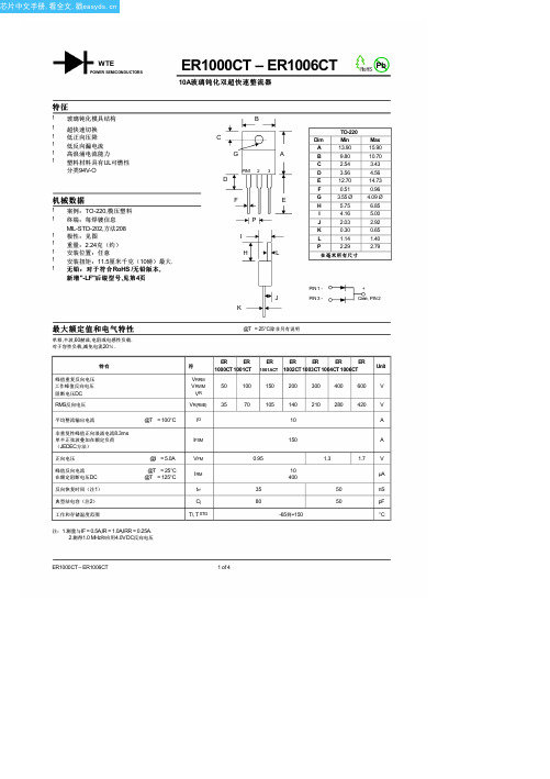
V ,正向电压(V) 图. 2典型正向特性
400
100
C,电容(pF)
10
0.1
1.0
10
100
V ,反向电压(V) 图. 4典型结电容
ER1000CT – ER1006CT
2 of 4
芯片中文手册,看全文,戳
标识信息
WTE ER100xCT
WTE ER100xCT x
极性
=制造商标志 =设备号 = 0,1,1A,2,3,4或6个 =对人体标示
封装信息
BULK
管尺寸
长×宽×高(mm)
525 x 31 x 6
数量
(PCS)
50
内箱尺寸
长×宽×高(mm)
555 x 145 x 95
数量
(PCS)
2,000
Note: 1. Anti-static tube, water clear color.
封装类型
TO-220 TO-220 TO-220 TO-220 TO-220 TO-220 TO-220
出货数量
50单位/管 50单位/管 50单位/管 50单位/管 50单位/管 50单位/管 50单位/管
1. Shipping quantity given isfor minimum packing quantity only. For minimum order quantity, please consult the SalesDepartment.
PIN 1 -
J
PIN 3 -
K
+ Case, PIN 2
最大额定值和电气特性
单相,半波,60赫兹,电阻或电感性负载. 对于容性负载,减免电流20%.
UL1004 浅译版
引言1 范围1.1 这些要求覆盖了设备中的马达和器材所要达到的要求。
本要求覆盖了串联、分流、混联或永久磁场类型的换向器马达,额定功率为5马力(3.7kW)或更小,可以是直流的也可以是交流的。
1.3 除了1.2中的马达外,本要求还涉及额定电压为7200V或比这个数值小的电动马达,单指那种排斥的换向器马达。
(与2001年7月改版)1.4 本要求适用于敞开和完全封闭的马达。
1.5 这些要求还可用于马达的配件和这些配件的连接件。
1.6 本要求不包括:a)阻抗保护马达的热保护和阻抗要求;阻抗保护马达用UL2111马达过热保护标准来判断。
b)其它取决于安装马达的终端器材的要求的马达保护c)密封的马达压缩机部件,是由UL984密封制冷的马达压缩机标准来衡量。
1.7 本要求不包括如《NFPA70国家电动代码》中所定义的用于危险境地的马达。
1.8 这些要求不包括终端使用器材的使用要求。
额定电流、正常和非正常使用时的温升、马达保护、内部漆包线和绝缘等特性,及类似特性由终端使用来衡量。
1.9 在特色、特征、组成物、材料、系统上有别于本标准,而其中牵涉到火灾、触电或伤害人身的危险的产品,需要以适当的附加组成物和试品设备作评定,对此类产品的用户持有的安全程度,以达到本标准的原本预期的意图。
特色、特征、组成物、材料、系统上与本标准的要求和规定冲突的产品不符合本标准。
建议采用修订的要求,使用方法一致,对于本标准所作的发展、修改、补充。
2 参考2.1 任何未注明日期的本标准的参考文献的代码和标准应被理解为最近的版本。
2A 术语表应本标准的目的,需使用以下定义:2A.1.13零件3.1 本标准涉及的产品的零件要符合关于本零件的要求,并且要在被认可的额定值和极限值范围内使用。
3.24测量单位4.1 不带括号的测试值是所需的,括号中的值为补充或约数。
5电流/马力的关系5.1由于本标准的意图,除另有规定,马达的尺寸为马达的直径即硅钢片平面上测得的定子框架(包括接线处片,散热片,外盒,及类似的只用于安装、冷却、组装或连接的配件)的外接直径。
ul 1004-1标准

ul 1004-1标准UL1004-1标准是美国电气制造商协会(UnderwritersLaboratories,简称UL)制定的一系列安全标准之一,主要用于规范电子产品的安全性能和认证流程。
本篇文章将详细介绍UL1004-1标准的主要内容、实施方式以及认证流程,以帮助相关企业和人员更好地了解和遵循该标准。
UL1004-1标准涵盖了电子产品的安全要求和测试方法,主要包括以下几个方面:1.电源和电池的安全性:标准要求对电源和电池进行过载、短路、过压等保护措施,以确保使用安全。
2.电气连接器:标准要求电气连接器必须具备良好的绝缘性能和机械稳定性,以防止意外脱落或损坏。
3.温度控制:标准要求电子设备必须具备合理的散热设计和过热保护措施,以防止设备过热引发安全隐患。
4.机械冲击和振动:标准要求电子设备在受到冲击和振动时,应能够保持稳定性和安全性。
5.防火和防电击保护:标准要求电子设备必须符合相关防火和防电击保护标准,确保使用者的安全。
二、实施方式为确保企业按照UL1004-1标准进行生产和认证,我们可以采取以下措施:1.加强宣传教育:通过举办培训班、研讨会等形式,提高企业和相关人员的安全意识,使其了解UL1004-1标准的重要性和要求。
2.建立质量管理体系:企业应建立完善的质量管理体系,确保生产过程符合UL1004-1标准的要求。
3.第三方认证:对于需要出口到美国市场的电子产品,企业应申请UL认证,确保产品符合UL1004-1标准的要求。
三、认证流程1.申请阶段:企业向UL认证机构提交申请,并准备相关文件和样品。
2.审核阶段:认证机构对申请进行审核,并对样品进行测试。
3.认证发证:如果产品符合UL1004-1标准的要求,认证机构将颁发UL认证证书,并允许在产品上使用UL标志。
认证流程的具体步骤和时间可能会因产品类型和测试要求而有所不同,企业应与认证机构进行详细沟通。
总之,UL1004-1标准是电子产品的安全标准之一,企业应按照该标准进行生产和认证。
Lorex LW2100 Series 色彩数字无线监控系统及室内 室外色彩相机(带音频)说明书
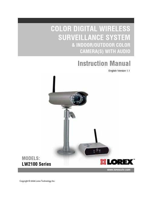
Instruction ManualEnglish Version 1.1 MODELS:LW2100 Series Copyright © 2008 Lorex Technology Inc.2Important Safeguards3ENGImportant SafeguardsIn addition to the careful attention devoted to quality standards in the manufacture process of your video product, safety is a major factor in the design of every instrument. However, safety is your responsibility too. This sheet lists important information that will help to assure your enjoyment and proper use of the video product and accessory equipment. Please read them carefully before operating and using your video product. 1. Read and Follow Instructions - All thesafety and operating instructions should be read before the video product is operated. Follow all operating instructions.2. Retain Instructions - The safety andoperating instructions should be retained for future reference.3. Heed Warnings - Comply with all warningson the video product and in the operating instructions.4. Polarization - Do not defeat the safetypurpose of the polarized or grounding-type plug.5. Power S ources - This video product shouldbe operated only from the type of power source indicated on the marking label. If you are not sure of the type of power supply to your location, consult your video dealer or local power company. For video products intended to operate from battery power, or other sources, refer to the operating instructions.6. Overloading - Do not overload wall outlets ofextension cords as this can result in the risk of fire or electric shock. Overloaded AC outlets, extension cords, frayed power cords, damaged or cracked wire insulation, and broken plugs are dangerous. They may result in a shock or fire hazard. Periodically examine the cord, and if its appearance indicates damage or deteriorated insulation, have it replaced by your service technician.7. Power-Cord Protection - Power supplycords should be routed so that they are not likely to be walked on or pinched by items placed upon or against them, paying particular attention to cords at plugs, convenience receptacles, and the point where they exit from the video product.8. Ventilation - Slots and openings in the caseare provided for ventilation to ensure reliable operation of the video product and to protect it from overheating. These openings must not be blocked or covered. The openings should never be blocked by placing the video equipment on a bed, sofa, rug, or other similar surface. This video product should never be placed near or over a radiator or heat register. This video product should not be placed in a built-in installation such as a bookcase or rack unless proper ventilation is provided or the video product manufacturer’s instructions have been followed.9. Attachments - Do not use attachmentsunless recommended by the video product manufacturer as they may cause a hazard.10. Water and Moisture - Do not use this videoproduct near water. For example, near a bath tub, wash bowl, kitchen sink or laundry tub, in a wet basement, near a swimming pool and the like.Caution: Maintain electrical safety. Power line operated equipment or accessories connected to this unit should bear the UL listing mark of CSA certification mark on the accessory itself and should not be modified so as to defeat the safety features. This will help avoid any potential hazard from electrical shock or fire. If in doubt, contact qualified service personnel.11. Accessories - Do not place this videoequipment on an unstable cart, stand, tripod, or table.The video equipment may fall, causing serious damage to the video product. Use this video product only with a cart, stand, tripod, bracket, or table recommended by the manufacturer or sold with the video product.Any mounting of the product should follow the manufacturer’s instructions and use a mounting accessory recommended by the manufacturer.Installationo A polarized plug has two blades with one wider than the other.o A grounding type plug has two blades and a third grounding prong. o The wide blade or the third prong is provided for your safety.o If the provided plug does not fit into your outlet, consult an electrician for replacement of the obsolete outletImporta t Safeguards4Service13. Servicing - Do not attempt to service thisvideo equipment yourself as opening or removing covers may expose you to dangerous voltage or other hazards. Refer all servicing to qualified service personnel.14. Conditions Requiring Service - Unplug thisvideo product from the wall outlet and refer servicing to qualified service personnel under the following conditions.A. When the power supply cord or plug isdamaged.B. If liquid has been spilled or objects havefallen into the video product.C. If the video product has been exposed torain or water.D. If the video product does not operatenormally by following the operating instructions. Adjust only those controls that are covered by the operating instructions. Improper adjustment of other controls may result in damage and will often require extensive work by a qualified technician to restore the video product to its normal operation.E. If the video product has been dropped orthe cabinet has been damaged.F. When the video product exhibits adistinct change in performance. This indicates a need for service.15. Replacement Parts - When replacementparts are required, have the service technician verify that the replacements used have the same safety characteristics as the original parts. Use of replacements specified by the video product manufacturer can prevent fire, electric shock or other hazards.16. S afety Check - Upon completion of anyservice or repairs to this video product, ask the service technician to perform safety checks recommended by the manufacturer to determine that the video product is in safe operating condition.17. Wall or Ceiling Mounting - The camerasprovided with this system should be mounted to a wall or ceiling only as instructed in this guide, using the provided mounting brackets.18. Heat - The product should be situated awayfrom heat sources such as radiators, heat registers, stoves, or other products (including amplifiers) that produce heat.Use19. Cleaning - Unplug the video product from thewall outlet before cleaning. Do not use liquid cleaners or aerosol cleaners. Use a damp cloth for cleaning.20. Product and Cart Combination - Video andcart combination should be moved with care. Quick stops, excessive force, and uneven surfaces may cause the video product and car combination to overturn21. Object and Liquid Entry - Never pushobjects for any kind into this video product through openings as they may touch dangerous voltage points or “short-out” parts that could result in a fire or electric shock. Never spill liquid of any kind on the video product22. Lightning - For added protection for thisvideo product during a lightning storm, or when it is left unattended and unused for long periods of time, unplug it from the wall outlet and disconnect the antenna or cable system. This will prevent damage to the video product due to lightning and power line surges. The manufacturer’s instructions and use a mounting accessory recommended by the manufacturer.General Precautions5ENGGeneral Precautions1. All warnings and instructions of this manual should be followed2. Remove the plug from the outlet before cleaning. Do not use liquid aerosol detergents. Use a water dampened cloth for cleaning3. Do not use this unit in humid or wet places4. Keep enough space around the unit for ventilation. Slots and openings in the storage cabinet should not be blocked5. During lightning storms, or when the unit is not used for a long time, disconnect the power supply, antenna, and cables to protect the unit from electrical surgeNote:This equipment has been tested and found to comply with the limits for a Class B digital device, pursuant to Part 15 of the FCC Rules. These limits are designed to provide reasonable protection against harmful interference in a residential installation. This equipment generates, uses, and can radiate radio frequency energy and, if not in-stalled and used in accordance with the instruction, may cause harmful interference to radio communications.However, there is no guarantee that interference will not occur in a particular installation. If this equipment does cause harmful interference to radio or television reception (which can be determined by turning the equipment on and off), the user is encouraged to try to correct the interference by one or more of the following measures:o Reorient or relocate the receiving antennao Increase the separation between the equipment and receivero Connect the equipment into an outlet on a circuit different from that to which the receiver is connectedo Consult the dealer or an experienced radio or television technician for assistanceThis equipment has been certified and found to comply with the limits regulated by FCC, EMC, and LVD. Therefore, it is designated to provide reasonable protection against interference and will not cause interference with other appliance usage.However, it is imperative that the user follows this manual' guidelines to avoid improper usage which may result in damage to the unit, electrical shock and fire hazard injuryIn order to improve the feature functions and quality of this product, the specifications are subject to change without notice from time to time.Features6Getting Started7ENGGetting StartedThe System comes with the following components:1 x WIRELESS RECEIVER1 x POWER ADAPTOR (FOR RECEIVER)1 x WIRELESS CAMERA(S)*1 x POWER ADAPTOR(S) (FORCAMERA) ** 1 of each provided with each Camera. Please see your System Package for the number of cameras included with your System.Wireless Receiver8 4231 2 35 6 7411Wireless Receiver Installation9ENGWireless Receiver Installation1.Connect the Antenna to the receiver.2.Connect the AV Cable to the back of the receiver. Connect the other end of the Cable to theVideo IN (Yellow) and Audio IN (White) ports on the TV, VCR or other viewing monitor.3.Plug the Receiver power cable into the 9V POWER input. Plug the power cable into a wall outletor surge protector.4.Place the receiver in a place that will have clear reception to your camera(s).Camera InstallationBefore you install the camera, carefully plan where and how it will be positioned, and where you will route the cable that connects the camera to the power adaptor or battery adaptor.Installation Warnings:•Aim the Cameras to best optimize the viewing area: Select a location for the camera that providesa clear view of the area you want to monitor, which is free from dust, and is not in line-of-sight toa strong light source or direct sunlight.•Avoid installing the cameras where there are thick walls, obstructions, or interference (i.e.transformers, microwave ovens or other electrical equipment) between the Cameras and theReceiver.•Select a location for the camera that has an ambient temperature between 14°F~113°F (-10°C~45°C)•Before starting permanent installation, have another person hold the camera for you while you verify its performance by observing the image on a monitor.Night VisionThis camera includes IR LEDs, which provide the camera with the ability to view images in low light conditions. It is important to use the provided power adaptor (and not the 9V DC Battery Adaptor) when using the camera for prolonged periods in low light conditions, as the LEDs will drain the battery more quickly than regular daytime use.10 Power Adaptor: Connect the Power Adaptor to the Female Barrel PowerWireless Connection LED IndicatorENGBATTERY PACK:1. Slide the cover off the Battery Pack.2. Insert 4 x AA Batteries (not included) into the Battery Pack. Make sure to correctly line up the Positive (+) and Negative (-) terminals of the batteries.Slide the Battery Pack cover back on.3. Connect the Battery Pack to the Camera. Toturn the Camera ON of OFF, simply connect theBatteryPack.NOTE: It is recommended to remove the batterypack from the camera when not in use.Wireless Connection LED IndicatorWhen the Receiver and Camera are connected:•The Camera will have IR LEDs indicating that there is a connection •The Wireless receiver Wiresless Indicator LED will be lit Battery: Connect the Camera Battery Adaptor cable to the Female Barrel Power termination on the camera. Connect a battery to the cable.CAMERA RECEIVERViewi g Mode Data Rate VGA Frames QVGA Frames 1062~1280 Kbps5~10 FPS 15~30 FPS 725~1062 Kbps 3~5 FPS 12~20 FPS 543~725 Kbps2~4 FPS 8~15 FPS 1234ZOOMAdvanced Menu ModeENGWhile in ZOOM MODE, you can Pan and Tilt the Camera image using the Arrow keys on the receiver.4. STATUS INDICATOR – The Status indicator message “No Connection” will appear when a camera cannot be found.Advanced Menu ModePress the MENU Button on the Receiver to enter MENU Mode. Use the ▲▼◄► Buttons to navigate UP, Down, Left or Right in the menu.1. AUDIO VOLUME – Use the Left and Right arrows to change the Audio Volume from 0 (off) to 20 (high).2. SCAN TIME – Sets the Auto Sequence to OFF (you must press the CAM Button on the receiver to see other channels), or 5 Second, 10 Second or 15 Second Auto scanning.NOTE: Before turning on the Auto Sequence, make sure all cameras are paired to the System.Use the ▲▼◄► arrows to navigate to each camera. Turn each camera to ON or OFF for Auto Detection.NOTE: There may be temporary signal losses for less than 1 second, due to the handshake process between the Camera and Receiver (when switching between channels).Camera Pairi n gCamera PairingThe System comes with camera(s) that have already been paired. The Pairing Function assigns each Camera to a different channel on the Wireless Receiver (up to 4 Cameras), and is necessary for configuring additional cameras.NOTE: It is highly recommended to pair the Cameras to the Receiver before permanently mounting the Cameras.1. Power on the Camera by connecting the Power Adaptor or Battery Pack. The transmit lights on the front of the Camera should be ON.2. Navigate to the PAIR CAM Menu option, by pressing the MENUButton on the Receiver, and using the ▲▼◄► keys to navigate. Selectthe desired Pairing channel.3. The screen will display the following message:Please Press Pair Key on Sensor SideThe number indicates the countdown of time left for the pairing process.4. Press the Pairing Button on the back ofthe Camera.Once the Pairing has been successfully completed:•The Camera Transmit indicatorLEDs will be illuminated•The Receiver Status IndicatorLED will be illuminated•The Camera Information (channel,transmission strength, etc.) willappear onscreen.TroubleshootingENGTroubleshootingIf you have problems with your System, there is often a quick and simple solution. Please try thefollowing:ProblemS olutionThere is no picture from a Camera. •Check all connections to the Camera. Make sure the adaptor is plugged in.•Make sure that the Cameras and Receiver are both ON.•Make sure that the camera is in range of the Receiver.•If using the battery adaptor, try replacing the BatteriesThere is Interference with the Camera Picture. •Make sure that each camera is within range, and that there are no large obstructions or interference •Try repositioning the camera, receiver or both to improve the reception.There are problems with the Audio. •Ensure that the volume on the TV is ON•Make sure that the sound is occurring within range of the Camera Microphone•If the unit emits a loud screeching noise (feedback), move the camera or receiver farther apart.Appendix #1 - Receiver SpecificationsENGAppendix #3 – Digital Wireless Technology Appendix #3 – Digital Wireless TechnologyThe Digital Wireless signal transmission type used by the Lorex LW2100 series is also known as FHSS –Frequency Hopping Spread Spectrum. This type of signal is highly resistant to deliberate jamming as itgenerates a channel hopping sequence using an algorithm generated by the receiver system.The 2.4GHz (2.400-2.483Ghz) band is being divided into sections or paths of 2MHz per section, and eachsecond the transmission signal hops hundreds of times in a specified sequence within this frequencyrange. The overall bandwidth required for frequency hopping is much wider then 2MHz however because transmission occurs only on a small section of this bandwidth at any given time, the signal beingtransmitted does not suffer from greatly reduced signal degradation and also avoids blocked paths otherdevices who act as sources of competing signals. The strength of the signal being transmitted is set to befrom 13.5-16dBm, which is much higher then the analog transmission signal allowed by authoritiesaround the Globe (see next 2 slides for a comparison).When an image is captured by the camera it is instantly converted from an analog to digital signal andpackaged into small packets. With each successful transmission via the 2Mhz paths discussed above, thepackets of information containing images are delivered to the receiver and decoded into analoginformation. The information can then be displayed on devices that are connected to the wireless receiver(RX).A device pairing process is required to synchronize the transmitter (TX, Camera) and the receiver (RX).This allows the transmitter and receiver to be on the same frequency and use the same algorithm forfrequency hopping. This ensures that only the paired transmitter and receiver can maintaincommunication signal by hopping to the same frequency paths at the exact same time. As a result, thechance that other devices within the same frequency range are on the same frequency, at the same timeand in the same order is extremely unlikely. Note that the pairing process is already done at the factoryfor products that ship within the same packaging. Only when add-on devices are purchased is a pairingprocess required.。
用于显微镜的控制器、相应的方法和显微镜系统[发明专利]
![用于显微镜的控制器、相应的方法和显微镜系统[发明专利]](https://img.taocdn.com/s3/m/d340d3ab690203d8ce2f0066f5335a8102d26698.png)
专利名称:用于显微镜的控制器、相应的方法和显微镜系统专利类型:发明专利
发明人:乔治·塞梅利斯,托比亚斯·威尔肯
申请号:CN202010085347.6
申请日:20200210
公开号:CN111552068B
公开日:
20220610
专利内容由知识产权出版社提供
摘要:用于显微镜的控制器被配置为接收表示伤口的图像数据,并且使用图像数据确定到伤口的视线。
控制器还被配置为输出用于显微镜的控制信号,所述控制信号指示显微镜将其光轴与视线对准。
申请人:徕卡仪器(新加坡)有限公司
地址:新加坡新加坡城
国籍:SG
代理机构:北京清亦华知识产权代理事务所(普通合伙)
代理人:宋融冰
更多信息请下载全文后查看。
自助图书杀菌机参数
工作温度:摄氏-10~50度。
环境湿度:10%~90%
产品外观可根据用户方要求定制(*)
机器具备杀菌作业进度指示灯,可提示杀菌作业的进度。
操作界面具备警示器设计,操作完成或发生错误时可自动发出声响提醒使用者;
机器具有紫外线指示灯,可提示紫外线灯管的工作状态。同时,在需要更换紫外线灯管时显示屏会有提示。(*)
机器能自动统计使用时间与使用次数。
柜体可灵活拆装,若柜体有碰撞或刮花,可以灵活更换柜体外壳部件。(*)
提供气旋式逐翻动书页之功能,达到同时提供书封与内页杀菌效果;
使用静电薄膜过滤器,能收集细微灰尘、细菌、病毒、环境中过敏元素;
有高效能集尘过滤器,拦截微小分子,不衍生臭氧或二氧化碳等有害物质;
机台上须设有抗UV材质透视窗,提供读者随时观看杀菌作业进度;
人性化操作介面设计(如:one touch),方便使用者操作;
每次操作于30秒内完成杀菌作业。
可调节杀菌时间,通过显示屏以图像及数字传达杀菌时间及杀菌状态并提示更换耗材等。
工作人员使用的按键,必须隐藏在上柜体内部,防止读者随意更改消毒时间(*)。
杀菌作业不会对书籍封面或内页留下刮痕或任何损害痕迹。
防止在杀菌过程中使用者打开杀菌室门,必须设有安全保护装置立即暂停运转。
设备
指标
福诺品牌自助图书杀菌机技术参数要求
自助图书杀菌机
功能要求
机器满足使用者自行操作图书杀菌作业的功能要求。
采用紫外线杀菌技术,配备8组(含)以上紫外线灯,并搭配天然香精强化杀菌效果;(*)
采用对人体无害植物杀菌素,增强杀菌效果,同时可去除图书中的致癌物质二甲苯,氨等异味。
美国传力传感器
美国传力传感器广州南创李工美国传力电子集团于1981年在美国芝加哥成立,是一家专业生产传感器及各种电子衡器等产品的知名企业集团,产品行销全美洲、欧洲、东南亚及澳洲等地区。
基于全球化的经营战略,传力在全球都具有多个分支机构。
在亚洲地区,主要分支机构有台北全立、南京传力、上海全立、常州传力、天津传力等。
传力电子衡器有限公司成立于1997年底,为集团在中国的生产基地,主要生产各类称重传感器、称重仪表、电子衡器以及自动控制检测设备等数十个系列、数百个品种,涵盖各种精度、量程。
在多个国家设立了分支机构或办事处,生产基地遍布美洲、东欧、中国等地;并在中国设立了广州南创传感器事业部,可为用户的实验和生产提供最佳的服务与解决方案。
南京传力拥有完备的科研开发机构、先进的机械制造设备、完善的检测实验手段。
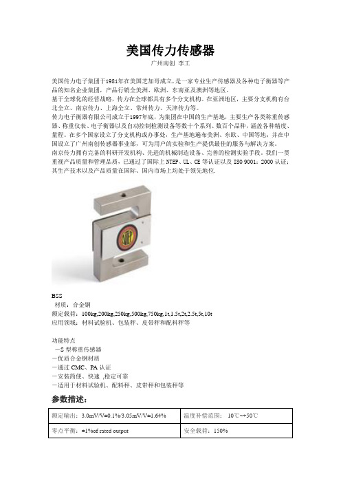
我们一贯重视产品质量和管理品质,已通过了国际上NTEP、UL、CE等认证以及ISO 9001:2000认证;其生产技术以及产品质量在国际、国内市场上均处于领先地位.BSS材质:合金钢额定载荷:100kg,200kg,250kg,500kg,750kg,1t,1.5t,2t,2.5t,5t,10t应用领域:材料试验机、包装秤、皮带秤和配料秤等功能特点-S型称重传感器-优质合金钢材质-通过CMC、PA认证-安装简便、快速,稳定可靠-适用于材料试验机、配料秤、皮带秤和包装秤等参数描述:额定输出:3.0mV/V±0.1%/3.05mV/V±1.64% 温度补偿范围:-10℃~+50℃零点平衡:±1%of rated output 安全载荷:150%蠕变:±0.03% of rated output 输入阻抗:387Ω±5Ω非线性:±0.03% of rated output 输出阻抗:350Ω±3Ω滞后:±0.03% of rated output 绝缘阻抗:≥5000MΩ(50V DC)重复性:±0.03% of rated output 推荐激励电压:10V DC/AC灵敏度温漂:≤0.002%of applied output/℃最大激励电压:15V DC/AC零点温漂:≤0.002% of rated output/℃导线长度:6m可用温度范围:-10℃~+70℃导线颜色:红(+E)黑(-E)绿(+S)白(-S)以上内容技术参数以《OIML60号国际建议》92年版为基础,最新具体变化可查看《JJG669—12transcell广州南创传感器事业部检定规程》美国传力传感器拉压S型称重传感器BSS-100kg, BSS-200kg, BSS-250kg, BSS-500kg, BSS-750kg, BSS-1t, BSS-1.5t, BSS-2t, BSS-2.5t, BSS-5t, BSS-10t BAB-5kg, BAB-7.5kg, BAB-10kg, BAB-15kg, BAB-20kg, BAB-30kg, BAB-50kg, BAB-75kg, BSS-100kg BSSD-15t, BSSD-20t BAC-5kg, BAC-7.5kg, BAC-10kg, BAC-20kg, BAC-30kg, BAC-50kg, BAC-100kg BS-750kg, BS-1000kg, BS-1500kg, BS-2000kg BSA-25kg, BSA-50kg, BSA-100kg, BSA-150kg, BSA-200kg, BSA-250kg BSE-500kg, BSE-1000kg, BSE-1500kg, BSE-2000kg BSS-ESH-1000kg, BSS-ESH -1500kg, BSS-ESH--2000kg, BSS-ESH-2500kg, BSS-ESH 5000kg 悬臂梁式称重传感器SBS-250lb, SBS-250kg, SBS-500kg, SBS-1000kg, SBS-1500kg, SBS-2000kg, SBS-2500kg, SBS-5000kg, SBS-7500kg, SBS-10000kg SB-5t, SB-10t, SB-15t, SB-20t SBSA-1500kg SBSK-25kg, SBSK- 50kg SBST-200kg, SBST-500kg, SBST-1000kg, SBST-2000kg SBT- 0.5t, SBT-1t, SBT-2t, SBT-3t广州南创电子科技有限公司仅供传感器事业部内部使用。
nirs 产品介绍
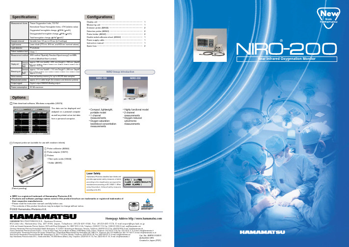
NIRO-100NIRO-300ISO 9001/ISO 13485EN 46001Certificate: 09 105 79045RheinlandHamamatsu Photonics K.K. has a Quality System according to MDD 93/42/EEC Annex ll.SpecificationsConfigurationsOptionsMeasurement itemsSample interval Light source Light detector Patient irradiation levelMeasurement method Data memory Measurement probes Output signal Power consumptionThe data can be displayed and analyzed on a personal computer as well as printed out as text data from a personal computer.NIRO lineup introduction1 Probe calibrator (A9344)2 Probe adapter (C9210)3 Probes• Fiber optic cords (C9343) • Holder (A9365)Display unit Measuring unit(Patent pending)Dimensions Weight Dimensions Weight123Emission probe (A8942) ·························································· 2Probe holder (A9340) ······························································· 2Display unit ·············································································· 1Measuring unit ········································································· 1Detection probe (A8943) ························································· 2Double-sided adhesive sheet (A9342) ····································· 1Power supply cable ·································································· 1Instruction manual ··································································· 1Spare fuse ···············································································2• Compact, lightweight, portable model • 1-channel measurements • Oxygen saturationlevel/blood concentration measurements• Highly functional model • 2-channel measurements • Oxygen-reduced cytochrome measurementsNear Infrared Oxygenation MonitorHomepage Address HAMAMATSU PHOTONICS K.K., Systems Division812 Joko-cho, Hamamatsu City, 431-3196, Japan, Telephone: (81)53-431-0124, Fax: (81)53-435-1574, E-mail:export@sys.hpk.co.jpU.S.A. and Canada: Hamamatsu Photonic Systems: 360 Foothill Road, Bridgewater, N.J. 08807-0910, U.S.A., Telephone: (1)908-231-1116, Fax: (1)908-231-0852, E-mail: usa@ Germany: Hamamatsu Photonics Deutschland GmbH: Arzbergerstr. 10, D-82211 Herrsching am Ammersee, Germany, Telephone: (49)8152-375-0, Fax: (49)8152-2658, E-mail: info@hamamatsu.de ,France:Hamamatsu Photonics France S.A.R.L.: 8, Rue du Saule Trapu, Parc du Moulin de Massy, 91882 Massy Cedex, France, Telephone: (33)1 69 53 71 00, Fax: (33)1 69 53 71 10, E-mail: infos@hamamatsu.fr United Kingdom:Hamamatsu Photonics UK Limited: 2 Howard Court, 10 T ewin Road, W elwyn Garden City, Hertfordshire, AL7 1BW, U.K., Telephone: (44) 1707-294888, Fax: (44) 1707-325777, E-mail: info@ North Europe: Hamamatsu Photonics Norden AB: Smidesv ägen 12, SE-171-41 Solna, Sweden, Telephone: (46)8-509-031-00, Fax: (46)8-509-031-01, E-mail: info@hamamatsu.se -Italy: Hamamatsu Photonics Italia S.R.L.: Strada della Mois, 1/E 20020 Arese (Milano), Italy, Telephone: (39)02-935 81 733, Fax: (39)02-935 81 741, E-mail: info@hamamatsu.itCat. No. SMPS1012E01AUG/2003 HPKCreated in Japan (PDF)Tissue Oxygenation Index, TOI (%)Normalized Tissue Hemoglobin Index, nTHI (relative value )Oxygenated hemoglobin change, O 2Hb ( mol/L )Deoxygenated hemoglobin change, HHb ( mol/L )Total hemoglobin change, cHb ( mol/L )Variable from 1/6 sec to 60 sec (in 9 settings )Laser diode (775 nm, 810 nm, and 850 nm: nominal values )Photodiode Class 1SRS method (Spatially Resolved Spectroscopy ) and MBLmethod (Modified Beer-Lambert )approx. 385 mm (width ) × 265 mm (height ) × 332 mm (depth )approx. 15.5 kg approx. 110 mm (width ) × 110 mm (height ) × 200 mm (depth )approx. 2.3 kgInternal backup memory for up to 48,000 data samples approx. 2.5 m cable length (for emission and detection probes )Digital output RS232C/Analog output 90 VA maximumCompact probe set (suitable for use with newborn infants)Data download software, Windows compatible (U9374)♦ NIRO is a registered trademark of Hamamatsu Photonics K.K.♦ Products and software package names noted in this product brochure are trademarks or registered trademarks of their respective manufacturers.• Please read the instruction manual carefully before use.• The contents of this product brochure may be subject to change without notice.Laser SafetyHamamatsu Photonics classifies laser diodes and provides appropriate safety measures or labels according to the classification as required for manufacturers according to IEC 60825-1. When using this product, follow all safety measures according to the IEC.©2003 Hamamatsu Photonics K.K.A highly functional tissue oxygenation monitor to meet a variety of needsThe NIRO-200 is a tissue oxygenation monitor that uses near infrared spectroscopy.The unit uses safe, faint light to measure the Tissue Oxygenation Index (TOI ) that shows the oxygensaturation level and the Normalized Tissue Hemoglobin Index (nTHI ) that shows the blood concentration as well as the concentration change in the oxygenated hemoglobin (∆O 2Hb ),deoxygenated hemoglobin (∆HHb ), and total hemoglobin (∆cHb ) in real time.Detection probeEmission probeBrain tissueNear infrared light with a wavelength of approxim ately 700–950 nm passes through body tissue comparatively well and the absorption of this light varies according to the oxygenation condition of the hemoglobin. Taking advantage of this, the m ethod called near infrared spectroscopy is used to non-invasively m easure the oxygenation levels of deep tissue in the brain, etc., and the oxygen concentration levels in blood.The NIRO-200 uses two very practical m ethods of near infrared spectroscopy.[ SRS method (Spatially Resolved Spectroscopy ) ]The Tissue Oxygenation Index (TOI ) and Normalized Tissue Hem oglobin Index (nTHI ) are calculated based on the change in the amount of light attenuation.[ MBL method (Modified Beer-Lambert ) ]The concentration change in the oxygenated hem oglobin (∆O 2Hb ), deoxygenated hem oglobin (∆HHb ), and total hemoglobin (∆cHb ) are calculated based on the tim e change of the light attenuation at the measurement location.• Monitoring brain oxygenation during heart surgery, etc.• Patient monitoring in ICUs, CCUs, and NICUs• Various clinical studies related to the responsiveness of oxygenation and blood metabolism in the brain• Study of muscle tissueoxygenation for sports medicine, rehabilitation, etc.Near InfraredOxygenation MonitorEasy-attachable probesThe probe holder is very small and can be in-stalled to small areas. In addition, the emission probe and detection probe can be removed from the holder and used without the holder.Equipped with a floppy disk driveContinuous, non-invasive measurement of tissue oxygenation using faint light.Easy operation by simply attaching the probes and pressing the start button.Useful in a wide variety of applications from management of brain oxygenation in operating rooms to clinical studies related to brain function,brain metabolism, muscle function, etc.Simultaneous measuring at two locations (two channels installed)It is possible to attach two sets of probes that do not interfere with each other.Measure concentration change in oxygenated hemoglobin, deoxygenated hemoglobin, and total hemoglobinMeasure the concentration change in the oxygenated hemoglobin (∆O 2Hb ), deoxygenated hemoglobin (∆HHb ), and total hemoglobin (∆cHb ) using the MBL method in addition to measuring oxygen saturation level and blood concentration.Easy operation by simply pressing the start button After pressing the start button, the unit automatically sets the optimum detection sensitivity and intensity of light irradiation in a short time and then begins monitoring. (Calibrations are unnecessary.)Transfer numerical value data to a personal computerIt is possible to transfer data to a personal computer using a floppy disk.Using the optional software, data can be rechecked easily.Safety and high reliabilityThe laser diode and photo detectors used weredeveloped by Hamamatsu Photonics for highly precise measurements. The intensity of light irradiation subjected to patients is kept at the safest Class 1 levels.ApplicationsMeasurement principles。
R-1004说明书 2.0
目录第1章:产品介绍 (2)1.1 概述 (2)1.2 DVR特性 (2)第2章:安装说明 (2)2.1 安全警告 (2)2.2 安装环境 (2)第3章:操作必读 (3)3.1 面板操作 (3)3.1.1 指示灯介绍 (3)3.1.2 功能键介绍 (3)3.2 背板连接 (3)3.3 摇控操作 (4)3.4 鼠标操作 (5)第4章:菜单设置 (5)4.1 系统设置 (5)4.2 录像设置 (7)4.3 摄像头设置 (8)4.4 运动侦测 (8)4.5 视频检索 (9)4.6 音频设置 (9)4.7 显示设置 (9)4.8 退出 (10)第5章:基本操作 (10)5.1 开机 (10)5.2 软件升级 (10)5.3 PTZ控制 (11)5.4 移动侦测 (11)5.5 搜索回放 (12)5.5.1 时间检索 (12)5.5.2 日历检索 (12)5.5.3 事件检索 (13)5.6 备份 (13)5.7 画质选择及硬盘可录像时间 (13)5.8 PC 客户端软件的使用 (14)5.8.1 登陆 (14)5.8.2 操作 (14)5.8.3 功能键介绍 (14)5.8.4 IE端说明 (16)5.8.5 IE浏览 (16)5.9 关机 (17)第6章:附录 (17)6.1 技术指标 (17)6.2 常见故障解答 (17)第一章产品介绍1.1概述本设备是专为安防行业设计的嵌入式硬盘录像机,它采用了嵌入式处理器和嵌入式操作系统,结合了计算机行业的最新技术,如视频/音频压缩和解压,TCP/IP网络远程控制,大容量硬盘存储等技术,使得系统具有高智能化及高稳定性。
本设备支持以太网、Internet等多种网络实现远程视频监看,操作简便。
可应用于小区、超市、工厂、公司、停车场及仓库等领域的安全防范。
本说明书适用于1004N(V)和1004(V)两个系列的产品。
本手册以R-1004N(V)产品为例进行详细说明,采用图片均以R-1004N(V)主机为准。
IR100红外气体分析仪操作手册

功耗:≦37VA 环境温度: -5° - +45℃ 环境湿度:90%RH以下 外壳:钢铁,室内使用 储存条件:
温度:-20 - 60℃ 湿度: 100%以下(避免凝结)
6.维护.…………………………………………………………………………………………6-1 6.1测量室清洁…………………………………………………………………………..……..6-2 6.1.1如何拆开和组装测量室……….…………………………..……………………………..6-2 6.1.2如何清洁测量室…...…………………………………..…………………………………6-7
(
)
流量: 大约1 L/min 压力: ≧500Pa 温度: 0-50℃ 粉尘: 1μm以下100μg/Nm3微粒 雾: 无
湿度: 避免过大
腐蚀性气体:
NOX <1000 ppm SO2 <1000 ppm HCL <1 ppm 其它 无
鼓风炉: CO 0-40%,CO2 0-30%,0-40% 0-50%
2-1
单位:mm
483 465
443
40
380
28
7
124.5
57.2
133
7
126+-20
电源开关
操作界面 前面
机架面板
面板剪切部 分(对安装 面板模式)
436
+2 -0
外部连接端子
第一Байду номын сангаас气体 (CO2)
第二种气体 (CO)
自动校验
侧板
样气出口 (RC1/4或NPT1/4)
希玛照度计参数
希玛照度计参数
希玛照度计是一种测量光照强度的仪器,常用于室内照明设计和照明效果评估。
其主要参数包括测量范围、分辨率、准确度、响应时间等。
测量范围一般为0-200,000勒克斯,可适用于不同场合的测量需求。
分辨率一般为1勒克斯,也有些高精度的希玛照度计可以达到0.1勒克斯的分辨率。
准确度是指希玛照度计测量结果与实际光照强度之间的偏差,通常为±(3%+2勒克斯)。
响应时间是指希玛照度计从暗到亮或由亮到暗的响应速度,一般为0.4秒左右。
除此之外,希玛照度计还有显示屏幕、数据记录、自动关机等功能,方便用户使用和数据处理。
- 1 -。
- 1、下载文档前请自行甄别文档内容的完整性,平台不提供额外的编辑、内容补充、找答案等附加服务。
- 2、"仅部分预览"的文档,不可在线预览部分如存在完整性等问题,可反馈申请退款(可完整预览的文档不适用该条件!)。
- 3、如文档侵犯您的权益,请联系客服反馈,我们会尽快为您处理(人工客服工作时间:9:00-18:30)。
HEXFET ® Power MOSFET
Fifth Generation HEXFET ® power MOSFETs from International Rectifier utilize advanced processing techniques to achieve extremely low on-resistance per silicon area. This benefit, combined with the fast switching speed and ruggedized device design that HEXFET power MOSFETs are well known for, provides the designer with an extremely efficient and reliable device for use in a wide variety of applications.
The D 2Pak is a surface mount power package capable of accommodating die sizes up to HEX-4. It provides the highest power capability and the lowest possible on-resistance in any existing surface mount package. The D 2Pak is suitable for high current applications because of its low internal connection resistance and can dissipate up to 2.0W in a typical surface mount application.
The through-hole version (IRL1004L) is available for low-
profile application.
l Advanced Process Technology l Ultra Low On-Resistance l Dynamic dv/dt Rating
l 175°C Operating Temperature l Fast Switching
l Fully Avalanche Rated Description
12/29/99
1
IRL1004S IRL1004L
D 2Pak IRL1004S TO-262IRL1004L
Parameter
Typ.
Max.
Units
R θJC Junction-to-Case
–––0.75R θJA
Junction-to-Ambient ( PCB Mounted,steady-state)*
–––
40
°C/W
Parameter
Max.
Units
I D @ T C = 25°C Continuous Drain Current, V GS @ 10V 130 I D @ T C = 100°C Continuous Drain Current, V GS @ 10V 92 A I DM
Pulsed Drain Current 520P D @T A = 25°C Power Dissipation 3.8W P D @T C = 25°C Power Dissipation 200W Linear Derating Factor 1.3W/°C V GS Gate-to-Source Voltage
± 16V E AS Single Pulse Avalanche Energy 700mJ I AR Avalanche Current
78A E AR Repetitive Avalanche Energy 20mJ dv/dt Peak Diode Recovery dv/dt 5.0
V/ns T J Operating Junction and
-55 to + 175T STG
Storage Temperature Range
Soldering Temperature, for 10 seconds
300 (1.6mm from case)
°C
Absolute Maximum Ratings
l
Logic-Level Gate Drive
PD - 91644A
IRL1004S/1004L
IRL1004S/1004L
IRL1004S/1004L
IRL1004S/1004L
IRL1004S/1004L
IRL1004S/1004L
IRL1004S/1004L
IRL1004S/1004L
IRL1004S/1004L。
