ASM焊线机资料
最新ASM焊线机操作指导书.pdf
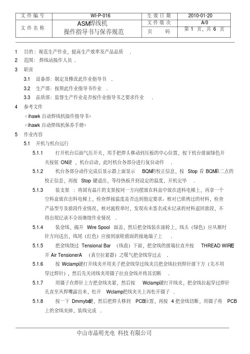
文件编号WI-P-016 生效日期2010-01-20文件名称ASM焊线机操作指导书与保养规范文件版次A/0页码第 1 页,共 6 页1目的:规范生产作业,提高生产效率及产品品质.2范围:焊线站操作人员.3职责3.1设备部:制定及修改此作业指导书.3.2生产部:按照此作业指导书作业.3.3品质部:监督生产作业是否按作业指导书之要求作业.4参考文件《ihawk自动焊线机操作指导书》《ihawk自动焊线机保养手册》5作业内容5.1开机与机台运行5.1.1打开机台后面气压开关,用手把焊头移动到压板的中心位置,按下机台前面绿色开关按钮ON键,机台启动,此时机台各部分进行复位动作.5.1.2机台各部分动作完成后显示器上面显示BQM的校正信息,按Stop看BQM第二点的校正信息,再按Stop键退出,等待热板升到设定的温度,开机完毕.5.1.3装支架:将固有晶片的支架按同一方向摆放在料盒中放在进料电梯上,再拿一个空料盒放在出料电梯上,检查焊接温度是否达到指定要求。
核对已烘烤过的材料,检查产品型号及前段作业情况,核对流程单时,发现有未签名或未记录的材料退回前段,不得出现记录不全而继续作业情况.5.1.4装金线,揭开Wire Spool面盖,然后把金线装在滚轮上,线头(绿色)应从顺时针方向送出,线尾(红色)应接到滚轮前面的接地端子上.5.1.5把金线绕过Tensional Bar(线盘)下面,把金线的前端拉直并按THREAD WIRE打开Air TensionerA(真空拉紧器)之吸气把金线穿过去.5.1.6按Wclamp键打开线夹并用夹子把金线穿过线夹且把金线拉到焊针前下方(先不用穿过焊针),然后先关闭线夹用镊子拉直金线并将其切断.5.1.7用镊子在焊针上方把金线夹紧,然后按Wclamp键打开线夹,把金线拉起穿过焊针孔直至从焊嘴露出来,松开Wclamp把线夹关上再松开镊子.5.1.8按一下Dmmybd键,然后把焊头移到PCB位置,再按4把金线切断,用镊子将PCB上的金线夹掉,装线完成.5.1.9测量焊针高度:按Inx键出现Sure to index LF?再按A键将材料送到焊线区,进入主菜单parameter再进入Reference Parameter测量PCB(Lead)和晶片(Die)和高度.5.1.10在Auto菜单中选择 1 start single bond 按Enter搜索PR,等搜索完PR停下来时按1焊一根线看是否正常,按0开始自动焊线作业.5.2型号更换与编程5.2.1调程序5.2.1.1选择菜单1MAIN→9 Disk utilities→0Hurd Disk program→1 load Bondprogram 选择相应的程序,出现sure to load program?按A确定,出现sure toload WH date ?后按B确定,出现Change Top plate W-Clamp,,stop to about后换上相对应的底板与压板后按Enter.5.2.1.2删除原有程序:进入菜单Teach→Delete Pragram把原来的程序删除掉.5.2.2编写程序5.2.2.1进入Teach→Teach Program教读一个新程序1)教读手动对点:在TeachAligmment菜单输入2(只有 1 Die 时)并按Enter编写手动对点Lead(支架)和Die(晶片)两个点;先对支架:把光标移到右起第一行最上面一个点确定,再移至该行最下面一个点确定。
ASM焊线机 ab339培训教材(光台电子)
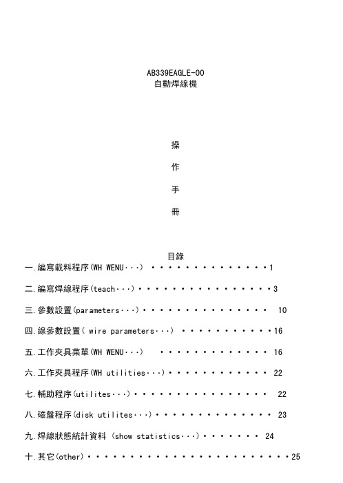
AB339EAGLE-00自動焊線機操作手冊目錄一.編寫載料程序(WH WENU•••) (1)二.編寫焊線程序(teach•••) (3)三.參數設置(parameters•••) (10)四.線參數設置( wire parameters•••) (16)五.工作夾具菜單(WH WENU•••) (16)六.工作夾具程序(WH utilities•••) (22)七.輔助程序(utilites•••) (22)八.磁盤程序(disk utilites•••) (23)九.焊線狀態統計資料 (show statistics•••) (24)十.其它(other) (25)十一.程序服務(process sercice) (25)十二.設置菜單(setup•••) (29)十三.自動菜單(auto•••) (30)十四.鍵盤功能 (32)十五.Bond TIP offset的調法 (34)十六.鋼咀的更換 (35)十七.壓板和熱板的更換 (35)一.編寫載料程序(WH WENU•••)以KP-3216SG為例0 device name 輸入程序名: KP-3216G1.Device scale Mum 選擇單位類型,這裡選Mum作為長度單位2.Number of units 輸入拉料單元個數:43.Device width 輸入支架寬度:50004.Device pitch 輸入兩個單元之間的距離:40875.Rad of index hole 輸入孔的半徑:486.Hole to LF head 輸入第一個孔至支架頭端的距離:207.Device length 輸入支架長度:16300•••8.More 下一頁0 cnter index hole 設置是否中心對准標志孔,這裡選NO1. orient dist 設置定向位置,容許晶片位置範圍,我們可不用,這裡更多的是適用于IC2.Rail edge to index hole 200 設置軌道邊緣到對應邊支架孔的距離,這裡我只需要適當增大一些支架邊緣到相對應一邊的距離.3.off ctr Bondpt -100 晶片中心進入點到孔距中心的距離4.Variable pitch 設置每兩個單元之間的距離•••,因為每兩個單元之間的距離有可能不同.1 setup Magazine•••0 scale 設置長度單位類型,這裡我們選擇Mum作為長度單位.1 length 設置料盒長度:166002.width 設置料盒寬度:57003.level 設置料盒格數:251/364. learn base-pitch-top 教學電梯高度5.Base 教學(設置)料盒底端至最近一格的距離:13006.pitch 每兩個槽之間的距離:4007.Top 教學料盒頂部至最近一格的距離:6502 learn LF parameter 這個過程是初始化教學拉料動作3 Fine Adjust••• 這個過程是對原拉料過程作適當數據修改2/36三.參數設置4 PARAMETER0 Bond parameter••• 焊線參數•••1 Base parameter 基本參數•••2 Reference parameter 測量鋼咀高度參數3 Light parameter 燈光參數7 (Q)Auto Loop 自動弧度(即三角形弧度)設置8 square Loop 矩形弧度設置B More•••40 Bond prameter0 Alignment tolerance L/D 設置允許認識支架大小誤差及晶片大小誤差範圍1 search delay(ms) L/D 設置搜索支架及晶片延時時間2 search Range(id) L/D 設置搜索支架及晶片的認識範圍3 Tail length 70 設置線尾長度4 Fire level 391 設置放電高度5 Fire level factor 35 設置線尾與放電棒之間的距離(放電高度補償值)6 lead offset 0 只適用IC7 EFO control 設置放電控制參數•••8 Heater control••• 熱板控制參數設置407 EFO control•••0 EFO parameter放電參數••••••1 EFO setting放電設置•••2 capillary info 鋼咀信息108001 EFO parameter•••0 unit type 0.1mil 單位mil與um的轉換1 wire size 10 線徑2 Gap wide warning volt 4500 放電能量4 EFO current(*0.01) 3250 MA 放電電流8 FAB size 30 燒球大小108002 EFO setting•••0 EFO BO X T Y PE 燒球類型1 wire type 線的種類2 Auto calc EFO time Y es 設置自動或手動放電3 EFO control mode FAB 燒的球的大小設置 設置燒球模式(Capi) 鋼咀壓下時球的大小設置10/364 Enable dual FAB NO 設置燒球是否有大小之區分108003 capillary info••••••7 New capillary data新的鋼咀數據•••8 delete capillary data刪除鋼咀數據9 copy capillary data fip→HD 將軟盤的鋼咀數據拷貝到硬盤A copy capil data HD→fip 將硬盤的鋼咀數據拷貝到軟盤1080037 New capillary data0 unit type 0.1mil mil與um的單位轉換1 capillary partno 鋼咀批號2 vendor type spt 鋼咀類型3 Double chamfer NO 設置是否是雙倍斜面4 Hole dia:H 18 鋼咀孔徑5 chamfer dia:CD 29 鋼咀斜口孔直徑6 chamfer angle:CA 120 鋼咀內斜角8 save capil file 保存文件408 Heater control0 Heater setting 加熱塊設置1 Heater Dly at bnd site 在焊線區域設置加熱延長時間2 Heating Dly at preht b1k 超前加熱3 heating dly at pstut b1k 延後加熱4083 heaging dly at pstut b1k0 delay time (*100ms) 0 延長時間409 more•••0 pre heat (*100ms) 0 預熱時間9 pre-heat all units NO 設置所有單元是否預熱41 Base parameter••• 基本參數設置0 standby power(dac) 10 0 設置第一.二點預置超聲波能量1 contact time (ms) 12 設置第一.二點接觸時間2 contact power (dac) 0 0 設置第一.二點接觸超聲波能量3 contact force (g) 30 80 設置第一.二點接觸壓力4 power delay (ms) 0 0 設置第一.二點超聲波能量延遲時間5 Bond time (ms) 10 10 設置第一.二點焊接時間6 Bond power (dac) 120 130 設置第一.二點超聲波能量7 Bond force (g) 70 130 設置第一.二點焊接壓力8 power factor (dac) 0 用于IC(平均分力)11/369 Force factor (g) 0 用于IC(機台預設的力)A WCl force open/close (g) 80 80 設置線夾張開,關閉的力)B More•••41 B More••••••0 scrub process control摩擦力控制1 BsoB Ball control•••BSOB球控制(先做球後打線)2 BSOB wire control•••3 BBOS Ball control•••BBOS球控制(先打線再在第二點做球)•••(先用5 TWin ball BSOB control 不同球的控制小能量燒球,打下時再燒一次.)41BO surub process control0 lst BND scrub control 第一點摩擦力設置(是否需要)1 lst BND surub directior x only 設置第一點摩擦力方向2 lst BND surub force 9 gm 設置摩擦力大小3 lst BND surub power 30 設置摩擦力能量•••4 2nd bnd sarab control 第二點摩擦設置41B04 2nd bnd scrub cortol•••0 scrub control mode 1 A 摩擦模式1 scrub direction Wiredir 摩擦方向2 scrub contact force 50 gm 設置接觸摩擦力3 scrub contact power 40 dac 設置接觸摩擦能量41B1 BSOB Ball control0 ball formation direction Wire dir 做球時鋼咀切斷線尾的方向1 loop base/ball offset 6 -10 設置在支架上做了球以後鋼咀上升的高度及線尾向左或右偏移值2 Ball thickness3 設置球的厚度3 scrub distance -10 設置摩擦移動的距離4 tail length 50 做球的線尾長度5 time base 1/2 10 8 在支架上做球時的兩次設置時間6 power base 1/2 50 20 設置在支架上做球時,前後兩次的能量7 force base 1/2 25 10 設置在支架上做球時,前後兩次的壓力8 slandby power 1/2 0 0 設置在支架上做球時,前後兩次預置超聲波能量12/36 9 power delay 1/2 0 0 設置在支架上做球時,前後兩次超聲波能量延遲時間A Bond all bsob ball first NO 設置是否先打一個球再打線(或者先全部做了球再打線)B More•••41B1B More•••0 contact time 1/2 0 0 設置在支架上做球時前後兩次接觸的時間1 contact power 1/2 0 0 設置在支架上做球時前後兩次接觸時超聲波的能量2 contact force 1/2 0 0 設置在支架上做球時前後兩次接觸時的壓力3 tail break time 50 smpl 設置在支架上做球後多長時間截斷線尾4 tail break zistance 25 ENC 設置在支架做球截斷線尾鋼咀上升的距離5 Ball offset speed 100% 設置在支架做的球偏移速度比例6 ball scrub speed 100% 設置在支架上做的球摩擦速度比例7 move TO FB POS speed8 ball formation shape41B1BB MORE•••1 BSOB stick detect NO 設置是否檢測在支架上做的球41B2 BSOB wire control0 2nd bond pt offset 20 BSOB模式第二焊點偏移位置1 search speed2 128 BSOB模式第二焊點搜索速度2 contact srch threshold 2 64 接觸搜索最低線度3 Base time 1/2 5 3 BSOB 模式時,第一.二焊點的時間4 Base power 1/2 75 40 在BOSB模式下,第一.二焊點的超聲波能量5 Base force 1/2 30 15 在 BOSB模式下,第一.二焊點的壓力43 light parameter 燈光參數設置•••0 PR light c/s 50 50 同柱光及側光燈的亮度設置(不是PR認識的燈光)1 panel light c/s 50 50 面板燈的同柱光及側光光源的設置2 PR LOW mag c/s 50 50 鏡頭倍數轉換小倍數時,同柱燈光及側光燈亮度的設置3 coax blue lgt HI/LO 50 50 設置同柱燈光藍光高倍數及低倍數的高度4 panel light test 面板照明燈光測試13/36•••4B3 Advance square loop 梯形弧度設置1 wire profile STD-SQ 設置弧度曲線輪廓2 LOOP height (auto) 130um 弧度(自動模式)高度設置3 neck/reverse angle 30 0 設置弧度頸部長度及反向角度4 LHT correction/scale os 0 20 設置弧度修正高度及轉向位移5 span length 25 % 設置弧度在轉向過程中的位移量的百分比6 2nd kink HT factor(%) 50 設置弧度第二次反沖高度的補償值7 trajectory profile tune auto 弧度軌跡輪廓運行方式設置8 pull ratio 0 牽引弧度比例,若放大弧線會在D點成彎由趨勢9 search speed 2 640 設置第二點搜索速度A Engineering loop control 設計弧度控制4B1 Engineering loop control 設計弧度控制2 loop height (manu) 145 um 設置弧度高度3 reverse height 13 manu 設置弧度轉向高度4 reverse distance (%) 35 設置弧度轉向位移百分比量5 reverse distance angle 0 設置弧度轉向(角度) (+後仰 -前傾)6 LHT correction/scale os 2 0 設置弧度轉向高度修正值/第二次反向位移7 span length 25 % 梯形弧度第二次轉向過程位移百分比8 span angle correction 0 flat 梯形弧度第二次轉向角度設置9 Wire length factor % 500 線長補償值設置A Trajectory profile tune manual 弧度軌道運行模式B Loop adjust parameters•••4B1B1 Trajectory parameters 設置弧度軌跡參數•••0 loop auto tuning profile ARC••• 設置弧度自動運行曲線輪廓模式 arocess1 search delay 6 smpl 搜索延遲6 smpl2 sync offset 10 smpl 自動校正時間3 DEL samples os 55 smp 設置拉弧減速4 profile peruine display 1 超前顯示自動弧度類型參數設置4 parameter7 (Q)auto loop•••4B2 Advance(Q)AUTO LOOP•••0 loop group type 1 h 弧度類型(無法改變)14/361 wire profile STD-QA 弧線輪廓模式2 loop height(auto) 155 um 弧高設置3 neck/reverse angle 25 35 弧度頸部高度及反轉角度設置4 LHT correction/scale os 20 20 弧高及第二個彎修正4B1 Engineering loop control1 loop group type 1 h 自動弧度類型( 無法改變)2 loop height (auto) 155 um 弧度高度設置3 reverse height 18 auto 反向高度設置4 neck angle factor % 25 頸部角度位移百分比5 reverse distance angle 35 反向位移角度6 LHT correction/scale os 20 20 修正高度及第二次反向位移9 wire lengtb factor % 500 設置線的總長A Trajectory profile tune manual 弧度軌跡運行模式B loop adjust parameters4B1B Loop adjust parameters0 Shape par ameters 形狀參數1 Trajectory parameters... 軌跡參數2 Motion parameters... 運動參數3 Portability parameters... 移值性參數4B1B1 Trajectory parameters0 Loop auto tuning profile Arc61 Search delay 10 smpl2 Sync offset 10 smpl3 Dec samples os 65 smpl4 Profile perwire display 1 顯示弧度輪廓模型AUTO LOOP及SQUARE LOOP 模式的軌跡如下:REV HT:弧度反轉高度,當其參數加大時,弧度會趨向偏離第二點即後仰REV DIST:弧度反轉位移,當其參數加大時,其弧度顯得前傾一些,但其實際高度略大一些.reverse distance angle:弧度反轉角度,當其參數增大時,弧度為後仰,反之. loop height correction:弧度高度修正,當其參數增大時,會後仰,反之.search delay:弧度搜索延遲,當其參數增大時,弧度頂部會顯得平坦一些.pull ratio: 拉弧比,當其參數加大時,弧度拉得松一點,反之拉得緊一些.*:square loop 是普通應用的不規則弧度.seale os:弧度第二次反向位移15/36 span lengtb:跨度長度,第一個彎與第二彎的跨度;四 線參數設置(wire paramelers•••)•••4 wire parameters 單線參數•••0 One-wire parameters 修改某根線參數1 Wire lengtb overview 顯示焊線長度•••2 Edit bond parameters 編輯焊線參數3 Edit loop group type 設置組的弧度類型•••4 Edit loop parameters 修改弧度參數•••5 Edit standoff ball 設置弧度線較長的球6 Edit stitch bond•••7 Edit scrub control 修改焊某些線第二點的摩擦8 Edit FAB control 修改•••FAB燒球方式的控制9 Edit ground wire control 設置基線控制A Edit Non-stick Detection 編輯偵測第一.二焊點是否打上B More•••14B More•••0 Edit bond point offset 編輯焊點偏移位置•••1 Edit tail break control 編輯截斷線尾控制2 Edit PBI control3 Auto pad control Map 焊點控制映像16/36五 工作夾具菜單16 WH Menu••••••(框架)0 Setup lead frame 設置導向支架1 Setup magazine 設置料盒••••••2 Learn LF para 初始化拉料教學3 Fine adjust 微調拉料•••4 Diagnostil診斷•••5 Service 服務設置導向框架:0 Device name 程序名稱1 Device scale 單位設置2 Number of units 拉料次數設置3 Device width 材料PCB寬度設置4 Device pitch 每單元針腳間的距離(兩個單元之間的距離)5 Rad of index hole 設置支架索引孔的半徑6 Hole to LF head 設置支架邊緣到第一個孔之間的距離7 Device length 設置支架長度下一頁0 Center index hole No 如果標志孔是在兩個單元的中間點則用Y es否則用No1 Orient dist 設置定向距離(偵察孔到支架邊緣)2 Rail edge to index H 設置軌道邊緣到索引孔的距離2003 Off ctr bndpt 晶片中心進入點到孔距中心的距離-100•••(每兩 4 Variable pitch變量孔距設置個單元之間的距離)設置料盒0 scale 設置單位類型(mcm/mil)1 Length 設置料盒長度166002 Width 設置料盒料寬度 57003 Level 設置料盒料槽數 254 Learn base-pitch-TOP 電梯高度教學17/36 5 Base 設置料盒底端至臨近第一格中間的距離13006 Pitch 設置料槽的寬度0.4cm7 TOP 設置料盒頂部至臨近第一格料盒中間的距離650162 Learn LF para ••• (用于IC)初始化拉料教學0 Indexer step size 10 設置馬達多少個脈沖距離1 Learn LF pitch ETc 教每個單元之間的距離2 Setup srch snr163 Fine adjust 微調0 Delta step size 10 設置馬達一個脈沖走的距離1 Adjust indexer offset 微調拉料2 Ist unit indexer offset 210 第一單元修正3 Left indexer offset -70 左夾片修正4 Right indexer offset -160 右夾片修正164 DiagnostiC•••診斷•••0 Home motor馬達愎位•••1 Track solenoid 軌道有關部位電磁閥開關診斷2 Sensor graphical display 感應器圖象顯示•••(左右夾片沿著軌道 3 Indexer init 不准用移動,中間會撞到壓板,從而損環拉料馬達)1640 Home motor•••0 Indexer 拉料馬達愎位1 Track 軌道馬達愎位2 Window clamp 壓板馬達愎位3 Left X elevator 左邊電梯x軸馬達愎位4 Left Y elevator 左邊電梯y軸馬達愎位5 Left Z elevator 左邊電梯z軸馬達愎位6 Right X elevator 右邊電梯x軸馬達愎位7 Right Y elevator 右邊電梯y軸馬達愎位8 Right Z elevator 右邊電梯z軸馬達愎位9 Home ejector 推料杆馬達愎位1641 Track solenoid••• 軌道有關部份電磁閥的診斷0 Toggle fixed sol 前軌道最左邊固定的電磁閥開關診斷1 Toggle left claw 前軌道左邊的進料夾片電磁閥開關診斷18/36 2 Toggle right claw 前軌道右邊的下料夾片電磁閥開關診斷3 Toggle right kicker 前軌道右邊彈出材料裝置的電磁閥開關診斷4 Input kicker in/out 左邊電梯彈出料盒裝置的電磁閥開關診斷5 Ouput kicker in/out 右邊電梯彈出料盒裝置的電磁閥開關診斷6 Open/close window clamp open/close 壓板上升.下降電磁閥開關診斷7 DC djector 推料杆的電磁閥開關診斷8 Vacuum off/on 真空電磁閥開關診斷9 LF IN request off 支架送入請求電磁閥開關診斷A LF Out request off 支架送出請求電磁閥開關診斷B Clean Air off 淨化空氣電磁閥開關診斷1642 sensor graphical display 感應器圖釋顯示165 service••••••0 Control parameter控制參數•••1 Working mode 工作模式2 Device offset 設備偏移調整1650 control parameter••••••(抓料部位)0 Indexer 拉料參數•••1 Window clamp 壓板參數•••2 Elevator 電梯參數•••3 Solenoid delay 電磁開關延遲參數•••4 Preheat setup預熱設置5 Miscellaneous 其它方面各種各樣的參數•••16500 Indexer•••0 Index time (ms) 1500 索引(拉料)時間設置1 Lead frame gap 20 mm2 Chk subsequent Idx hole disable/enable 檢查跟隨的索引孔設置•••3 LF jam protection 設置材料運送過程中保護安全參數•••4 Indexer speed control 設置材料運送過程中速度控制165003 LF J am protection0 Protection mode enable 保護方式設置1 into mag current limit 200 進料夾片極限設置2 Kickout current limit 220 彈出材料(相關索引部位)極限設置165004 Indexer speed control•••0 Index first unit speed 7 索引材料至焊線壓區域之前單元傳遞速度1 Index one unit speed 7 索引第一單元傳遞速度19/362 Indexer move back speed 7 索引後面單元移動速度3 Index into mag speed4 設置送料至右邊料盒裡的速度4 Leadframe kickout speed 4 設置支架被彈出時的速度5 Clear track speed 4 設置清除軌道內材料的速度6 Search ist unit speed normal 設置搜索第一單元的速度16501 Window clamp••• 壓板設置•••0 WC speed prof mapping 設置壓板升降在高速和低速度時的升降方式:0 high speed fast1 low speed normal•••1 open w/c 設置升起壓板的參數項•••2 Close w/c 設置下降壓板的參數項3 Detect vacuum No 設置真空檢測4 Detect pressure Y es 設置壓強檢測5 T/P & W/C Type eagle 設置溫度及壓板類型6 W/C With fork No 設置壓板附架部份(支叉點)165011 open W/C•••0 Open speed low 設置壓板升起的速度方式1 open position 430 設置壓板升起時的位置高度2 Delay after open w/c o ms 設置壓板升起後延遲的時間3 pre-open speed low 設置預先打開壓板的速度方式4 pre-open oposition 0 設置預先打開壓板的位置5 Delay after pre-open w/c 0 設置預先打壓板以後延遲時間165012 close W/C•••0 Close speed low 設置降下壓板的速度方式1 Close position 200 設置壓板下降的位置2 Delay after close w/c 100 設置壓板下降以後延遲多長時間3 Pre-close speed low 設置預先降下壓板的速度方式4 Pre-close position 0 設置預先降下壓板的位置5 Pre-close enable select 預先降下壓板的選擇項6 Delay after preclose w/c 預先降下壓板延遲時間1650125 Pre-close enable select0 All units No 設置所有單元是否預先降下壓板1 Ist units of lst LF No 設置第一根支架的第一單元是否預先降下壓板 2 Ist unit of subseq LF No 設置需求的支架的第一單元是否預先降下壓板20/36 1650126 Delay after preclose w/c 降下壓板的延遲時間0 All units 0 ms 設置所有單元1 Lst unit of lst LF 0 ms 設置第一單元2 Ist unit of subseq LF 0 ms 設置第一單元及後面的單元16502 Elevator•••0 Y clamp/unclamp steps 250 250 設置電梯y軸方向關閉打開的馬達步數1 In mag index alternative 0 slot 設置左邊電梯取舍多少個料槽2 Out mag index alternative 1 slot 設置右邊電梯取舍多少個料槽3 Z-Level below home -80 設置電梯高度在零點下面多少即z軸高度4 Chg in-mag if no in LF Enable 設置如果進料盒內沒有材料是否更換料盒5 Chg out-mag if no in LF Enable 設置右邊料盒內不再進入材料時是否需要更換料盒 6 Input elevator premove disable 設置左邊電梯是否預先移動7 Mag guide x-slot pos middle 設置料盒框架x軸位置8 Input mag orient check No 設置左邊輸入料盒定位檢測9 Output mag orient check No 設置右邊料盒定位檢測16503 solenoid delay••• 電磁閥延遲時間0 Fixed claw op/cl (ms) 50 70 設置進料處固定夾片打開/關閉延遲時間1 Left claw op/cl (ms) 50 70 設置遲左邊夾片打開/關閉延遲時間2 Right claw op/cl (ms) 50 70 設置右邊夾片打開/關閉延遲時間3 Right kicker op/cl(ms) 50 70 設置右邊彈出材料裝置打開/關閉延遲時間4 Vacuum on/off (ms) 50 50 真空開關延遲時間16504 preheat setup•••0 Heater type normal 設置加熱塊類型1 LF heating position fix pos 設置支架加熱位置2 Get next LF AT LAST UNIT No 在最後一個單元時是否預熱進來一下個支架 16505 Miscellaneous•••零碎方面設置0 Device type noraml 設置裝置類型1 LF Eject retry number 3 設置重試推料多少次2 ejector bar type ext(std)3 LST/L & R offset update No 左右第一位置偏移是否更換4 R-TO-R buffer circuit absent 轉換線路設置(送料模式設置)(present)1651 working mode•••21/36 0 WH Dryrun No 工作夾具運行真與假設置1 PR Indexing every 設置索引認識方式2 Out elevator move dir down 下料電梯運行方向3 Machine type STD 機器身份設置4 WH configuration type STD 工作夾具配置類型1652 Device offset•••裝置偏移位置設置0 Change 改變•••1 Adjust 調准16520 change0 L X-Elev 0 改變左邊料盒框架的X軸方向距離1 L Y-Elev 0 改變左邊料盒框架的Y軸方向距離2 L Z-Elev 0 改變左邊料盒框架的Z軸方向距離3 R X-Elev 0 改變右邊料盒框架的X軸方向距離4 R Y-Elev 0 改變右邊料盒框架的Y軸方向距離5 R Z-Elev 0 改變右邊料盒框架的Z軸方向距離6 Trak 0 改變軌道的寬度 16521 Adjust•••0 Delta step size 10 馬達數據步進次數1 L X-elev 調准左邊料盒框架的X軸方向距離2 L Y-elev 調准左邊料盒框架的Y軸方向距離3 L Z-elev 調准左邊料盒框架的Z軸方向距離4 R X-elev 調准右邊料盒框架的X軸方向距離5 R Y-elev 調准右邊料盒框架的Y軸方向距離6 R Z-elev 調准右邊料盒框架的Z軸方向距離7 track 調准軌道的寬度六 工作夾具程序17 WH utilities•••o clear track 清除軌道1 Index in-elevator 1 slot 進料電梯料盒索引的格數2 Index Out-Elevator 1 slot 出料電梯料盒索引的格數3 Clear Input Magaine 清除進料電梯上所有的料盒4 Clear Output Magaine 清除出料電梯上所有的料盒22/365 Open/close Track 打開/關閉軌道6 Open/close Window clamp open 設置打開/關閉壓板方式狀態7 Hone Motor…馬達復位8 Track Solenoid … 軌道電磁閥9 Move Indexer Center 索引(位料)部位移動位置 17 A More…0 Sensor Display…感應器狀態顯示1 Auto Index Test 自動推料測試七 輔助程序18 Utilities 程序(輔助)0 Manual & CRT Bond … 手動補線及單焊一根線1 Set statistics limit … 焊線狀態設置極限2 Stanelby Mode 學習模式3 Align Camer 鏡頭校准4 Power Control …超聲波能量控制5 Test Tower Light 500 報警燈報警頻率測試180 Manccal & CRT Bond …1 Start CRT Bond 僅焊一根線2 Contact Search 接觸搜索3 Bond Power 1/2 120 145 焊接時第一.二點超聲波能量設置4 Bond time 1/2 10 8 焊接時第一.二點時間5 Bond force 1/2 70 100 焊接時第一.二點壓力6 Bond Height 1/2 5 5 焊接時第一.二點鋼咀上升高度181 Set Statistics Limit 設置參數極限0 Total Wire Length 0 m 總的線長1 Capil Warn 0 *100 鋼咀滿數警告2 Capil Stop 0 *100 鋼咀滿數停止3 Unit Warn 0 *100 焊完多少單元警告4 Unit Stop 0 *100 焊完多少單元停止5 Wire 0 *100 用線量6 Wire Clamp Stop 0 *10k 線夾停止7 Etorch stop 0 *10k8 Missing Ball 0 燒球失誤總數23/369 Skip Die Total 0 跳過晶片總計A Skip Die Unit 0 跳過晶片單元數量181A More0 Lead Quality Fail 0 第二點不良1 Lead Tolerence Fail 0 第二點容許不良2 Die Quality Fail 0 第一焊點不良3 Die Tolerence Fail 0 第一點容許不良4 Local Lead Fail 0 支架認識不良5 Input Magaime Error 0 載料電梯錯誤6 Output Magaine Error 0 御料電梯錯誤7 Position Error 位置錯誤8 Window Clamp Error 0 壓板升降錯誤9 Non Stick Error 0 打不粘184 Power Control0 BH/XY table/Indxer power ON 焊頭X-Y工作台拉料能量開關1 Solenoid /Elevator power ON 電磁閥.電梯電量開關2 EFO/Heater/Misc power ON 放電.加熱塊等能量開關3 Heater Control Mode ON 加熱塊控制模式開關八 磁盤程序19 Disk utilities 磁盤程序0 Hard Disk program 硬盤程序1 Floppy Disk program 軟盤程序2 Setup Assistant. 輔助設置4 Bond prgram Type Eagle 焊接程序類型 190 Hard Disk Program 硬盤程序0 Save Bond Program 保存焊線程序到硬盤1 Load Bond Program 調出硬盤裡面的焊線程序2 Delete Bond Program 刪除硬盤上的焊線程序3 Copy Bond Prog To Fdisk 拷貝硬盤上的焊線程序到軟盤4 Load Olp Data File 調出OLP數據5 Work Holder Parameter 工作夾具參量6 Work Holder DataBase 工作夾具數據庫7 Verification Program 檢驗程序8 Advance Loop Database 前置弧度數據庫24/36 1905 Work Holder Parameter0 Load WH Parameter 登錄工作夾具參量1 Save WH Parameter 存入工作夾具參量2 Delete WH Parameter File 刪除工作夾具參量文件3 Copy WH Para To FD 拷貝工作夾具參量件到軟盤1906 Work Holder Database 工作夾具數據庫0 Save WH Database 存入工作夾具數據庫1 Load WH Database 登錄工作夾具數據庫2 Delete WH Database 刪除工作夾具數據庫3 Copy WH Database to FD 拷貝工作夾數據庫到軟盤1908Advance Loop Database 前置弧度數據庫0 Save Loop Database 載入(保存)弧度數據庫1 Load Loop Database 登錄弧度數據庫2 Delete Loop Database 刪除弧度數據庫3 Display Loop Database 顯示弧度數據庫4 Copy Loop Database to FD 拷貝弧度數據庫到軟盤192 Setup Assistant 輔助設置0 Program Setup Ctrl... 程序控制設置1 Cali Cpaillary Oibration 鋼咀參數4 Bond Program Type EAGLE 焊線程序類型九 焊線狀態統計資料15 Show statistics.... 顯示統計狀況0 Show Bond Statistic 顯示焊線狀況統計資料1 Utilisation Breakdown 統計故障時間2 List Top 10 Assists 顯示前面10個輔助程序3 List Top 10 failures 顯示前面10個故障4 Display Error Log 顯示錯誤數據6 Reset Bond Statistic All 清除焊線狀態統計方式7 Reset Statistics 清除所有的統計資料8 Set statistics 設置狀態統計狀態極限9 saw Stats Val To FD 保存資料到軟盤25/36十 其它方面菜單5 other2 Tower Light Setup 報警燈設置52 Tower Light Setup0 Machine Running Green 設置機器運轉時警示燈的顏色1 Mathine Idle Y ellow 設置機器閑置狀態時警示燈的顏色2 Machine Error Red 設置機器故障時警示燈的顏色3 Material Waiting Green 設置機器運轉時待料警示燈的顏色十一 程序服務Function Code=15菜單Proess Service2002108 Process Service 程序服務0 Bonding Control 焊接控制1 Speed Control 速度控制2 PR Control 認識控制3 Looping Control 弧度控制4 Heater Control 熱板控制5 Parameter Range Control 參數範圍控制6 Statistics Mangement 統計管理7 Seccerity Mangement 安全管理8 Misc Control 其它方面控制1080 Bonding Control... 焊接控制0 EFO Control... 放電控制1 Skip Die Control 晶片跳過控制2 Surub Control 摩擦控制3 Bond Process Control 焊接壓力控制4 Safety Control 安全設備控制5 Bond Stick Detection 檢測是否打不粘6 Butterfly Bond Control Disable 蝶式焊接控制10800EFO Control ...0 EFO delay ... 5 放電延長時間設置1 EFO parameters ... 放電參數26/362 EFO Setting ... 放電設置3 Capilery Info ... 鋼咀信息4 Ball formation Monitor ... 球形成監視108001 EFO Parameters ... 放電參數0 Unit Type 0.1 mil 單位類型1 Wire Size 10 線徑大小設置2 Gap Wide Warning Volt 4500 放電間距寬度警告電壓設置4 EFO Current (*0.01) 3250 MA 放電電流設置8 FAB Size 30 燒球大小設置108002 EFO Setting ...0 EFO Box Type STD 放電箱類型1 Wire Type GOLD 線的種類2 Auto Calc EFO Time Y es 設置預燒(放電)時間開關3 EFO Control Mode FAB 放電控制模式設置 FAB 燒成的球的大小設置Capil 球被壓扁後的大小設置4 Enable Dual FAB NO 設置是否允許燒兩種不同類型的球108004 Ball Formation monitor ...1 Contamination level C 燒球雜質能級設置2 Abnormality level C 異常能級設置3 Enable BFM NO10801 Skip Die Control0 Ink Size (Radius) 10 pix 晶片上認識不到的陰影半徑範圍設置1 Skip Bad Die NO 設置不認識晶片是否跳過2 Skip Nissing Die ... 設置跳過未認到的晶片3 Skip Ink/Bad Unit NO 設置跳過認不到的單元4 Skip by special pat ... 設置通過特殊的方法跳過認不到的晶片5 Skip By Mark Cheeking ... 通過標記檢查跳過設置6 Max skipped die ctrl... 設置最多跳過的晶處數量7 F1 Skip unit num of die No 設置F1跳過整個單元內的晶片數量108012 skip missing die...0 Vil before check ink Y es 用于IC1 Skip missing die No 檢測不到晶片時是否跳過27/36 108014 Skip by special pat...0 Check special pat No 設置是否檢查特殊的焊點1 Teach special pat... 教學特殊的焊點2 Ship (IF pat not found) Y es 設置當特殊的焊點沒被發現時是否跳過108015 Skip by mark checking ...0 Skip die by mark check No 設置是否通過特殊標記跳過晶片1 Ink size (radius) 10 piz 設置陰影半徑2 Chk rej-indicator only No 是否是以該範圍檢測3 Teach reject indicator 檢測範圍設置108016 Max skipped die ctrl...0 Max continuous skip die 30 設置最多連續跳過多少顆晶片1 Check max skop die num disable 設置是否檢查最多跳過多少顆晶片2 Max skip die/strip 100 設置最多跳過的晶片條紋數量3 Strip skip die control No10802 Scrub control 摩擦力控制0 Ist BND scrub settings... 設置第一焊點摩擦力1 2nd bnd scrub settings... 設置第二焊點摩擦力10803 Bond process control0 Ctact srch threshold 1/2 16 64 設置第一.二焊點搜索接觸壓力最低極限1 Ist wire power offset 02 Ist wire time offset 0 ms3 Release power (dac) 0 0 設置釋放第一.二焊點超聲波能量4 Release force (g) 30 305 Tail break energg 0 設置線尾截斷能量6 Pwr compensation method wiredir 設置能量補償方法7 Auto ctact srch setup... 自動接觸搜索設置8 Bond enhancer... 焊接增強器108037 Auto ctact srch setup...0 Search mode disable 設置搜索模式1 Search tolerance 32 設置搜索公差2 Search speed 128 設置搜索速度3 Search delay 160 ms 設置搜索延遲時間4 Search level -150 設置搜索高度5 Search wire map 設置是否搜索線的圖形。
ASM焊线机操作指导书(word版)

ASM焊线机操作指导书Through the process agreement to achieve a unified action policy for different people, so as to coordinate action, reduce blindness, and make the work orderly.编制:___________________日期:___________________ASM焊线机操作指导书温馨提示:该文件为本公司员工进行生产和各项管理工作共同的技术依据,通过对具体的工作环节进行规范、约束,以确保生产、管理活动的正常、有序、优质进行。
本文档可根据实际情况进行修改和使用。
1 目的:规范生产作业, 提高生产效率及产品品质.2 范围:SMD焊线站操作人员.3 职责3.1 设备部:制定及修改此作业指导书.3.2 生产部:按照此作业指导书作业.3.3 品质部:监督生产作业是否按作业指导书之要求作业.4 参考文件《ihawk自动焊线机操作指导书》《ihawk自动焊线机保养手册》5 作业内容5.1 开机与机台运行5.1.1 打开机台后面气压开关, 用手把焊头移动到压板的中心位置, 按下机台前面绿色开关按钮ON键, 机台启动, 此时机台各部分进行复位动作.5.1.2 机台各部分动作完成后显示器上面显示BQM的校正信息, 按Stop看BQM第二点的校正信息, 再按Stop键退出, 等待热板升到设定的温度, 开机完毕.5.1.3 装支架:将固有晶片的支架按同一方向摆放在料盒中放在进料电梯上, 再拿一个空料盒放在出料电梯上, 检查焊接温度是否达到指定要求。
核对已烘烤过的材料, 检查产品型号及前段作业情况, 核对流程单时, 发现有未签名或未记录的材料退回前段, 不得出现记录不全而继续作业情况.5.1.4 装金线, 揭开Wire Spool面盖, 然后把金线装在滚轮上, 线头(绿色)应从顺时针方向送出, 线尾(红色)应接到滚轮前面的接地端子上.5.1.5 把金线绕过Tensional Bar(线盘)下面, 把金线的前端拉直并按THREAD WIRE打开Air TensionerA(真空拉紧器)之吸气把金线穿过去.5.1.6 按Wclamp键打开线夹并用夹子把金线穿过线夹且把金线拉到焊针前下方(先不用穿过焊针), 然后先关闭线夹用镊子拉直金线并将其切断.5.1.7 用镊子在焊针上方把金线夹紧, 然后按Wclamp键打开线夹, 把金线拉起穿过焊针孔直至从焊嘴露出来, 松开Wclamp把线夹关上再松开镊子.5.1.8 按一下Dmmybd键, 然后把焊头移到PCB位置, 再按4把金线切断, 用镊子将PCB上的金线夹掉, 装线完成.5.1.9 测量焊针高度:按Inx键出现Sure to index LF?再按A键将材料送到焊线区, 进入主菜单parameter再进入Reference Parameter测量PCB(Lead)和晶片(Die)和高度.5.1.10在Auto菜单中选择1 start single bond 按Enter搜索PR, 等搜索完PR停下来时按1焊一根线看是否正常, 按0开始自动焊线作业.5.2 型号更换与编程5.2.1 调程序5.2.1.1 选择菜单1MAIN→9 Disk utilities→0Hurd Disk program→1 load Bond program 选择相应的程序, 出现sure to load program?按A确定, 出现sure to load WH date ?后按B确定, 出现Change Top plate W-Clamp……stop to about后换上相对应的底板与压板后按Enter.5.2.1.2 删除原有程序:进入菜单Te ach→Delete Pragram把原来的程序删除掉.5.2.2 编写程序5.2.2.1 进入Teach→Teach Program教读一个新程序1)教读手动对点:在Teach Aligmment菜单输入2(只有1 Die 时)并按Enter编写手动对点Lead(支架)和Die(晶片)两个点;先对支架:把光标移到右起第一行最上面一个点确定, 再移至该行最下面一个点确定。
ASM焊线机操作指导书课件.doc
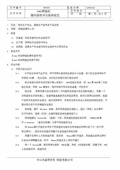
文件编号WI-P-016 生效日期2010-01-20文件名称ASM焊线机操作指导书与保养规范文件版次A/0页码第1 页,共 6 页1 目的:规范生产作业,提高生产效率及产品品质.2 范围:焊线站操作人员.3 职责3.1 设备部:制定及修改此作业指导书.3.2 生产部:按照此作业指导书作业.3.3 品质部:监督生产作业是否按作业指导书之要求作业.4 参考文件《ihawk 自动焊线机操作指导书》《ihawk 自动焊线机保养手册》5 作业内容5.1 开机与机台运行5.1.1 打开机台后面气压开关,用手把焊头移动到压板的中心位置,按下机台前面绿色开关按钮ON键,机台启动,此时机台各部分进行复位动作.5.1.2 机台各部分动作完成后显示器上面显示BQM的校正信息,按Stop 看BQM第二点的校正信息,再按Stop 键退出,等待热板升到设定的温度,开机完毕.5.1.3 装支架:将固有晶片的支架按同一方向摆放在料盒中放在进料电梯上,再拿一个空料盒放在出料电梯上,检查焊接温度是否达到指定要求。
核对已烘烤过的材料,检查产品型号及前段作业情况,核对流程单时,发现有未签名或未记录的材料退回前段,不得出现记录不全而继续作业情况.5.1.4 装金线,揭开Wire Spool 面盖,然后把金线装在滚轮上,线头(绿色)应从顺时针方向送出,线尾(红色)应接到滚轮前面的接地端子上.5.1.5 把金线绕过Tensional Bar (线盘)下面,把金线的前端拉直并按THREAD WIR打E开Air TensionerA (真空拉紧器)之吸气把金线穿过去.5.1.6 按Wclamp键打开线夹并用夹子把金线穿过线夹且把金线拉到焊针前下方(先不用穿过焊针),然后先关闭线夹用镊子拉直金线并将其切断.5.1.7 用镊子在焊针上方把金线夹紧,然后按Wclamp键打开线夹,把金线拉起穿过焊针孔直至从焊嘴露出来,松开Wclamp把线夹关上再松开镊子.5.1.8 按一下Dmmybd键,然后把焊头移到PCB位置,再按 4 把金线切断,用镊子将PCB上的金线夹掉,装线完成.5.1.9 测量焊针高度:按Inx 键出现Sure to index LF? 再按A键将材料送到焊线区,进入主菜单parameter 再进入Reference Parameter 测量PCB(Lead)和晶片(Die)和高度.5.1.10 在Auto 菜单中选择 1 start single bond 按Enter 搜索PR,等搜索完P R停下来时按1 焊一根线看是否正常,按0 开始自动焊线作业.5.2 型号更换与编程5.2.1 调程序5.2.1.1 选择菜单1MAIN→9 Disk utilities →0Hurd Disk program →1 load Bondprogram 选择相应的程序,出现sure to load program? 按A确定,出现sure toload WH date ? 后按B确定,出现Change Top plate W-Clamp ,, stop to about后换上相对应的底板与压板后按Enter.5.2.1.2 删除原有程序:进入菜单Teach→Delete Pragram 把原来的程序删除掉.5.2.2 编写程序5.2.2.1 进入Teach→Teach Program 教读一个新程序1)教读手动对点:在TeachAligmment 菜单输入2(只有 1 Die 时)并按Enter 编写手动对点Lead(支架)和Die(晶片)两个点;先对支架:把光标移到右起第一行最上面一个点确定,再移至该行最下面一个点确定。
ASM设备中文资料文档

ASM设备中文资料ASM Teach流程一.设定及教读L/F二.设定及教读Mag.三.调整各部位的M/C data四.教读L/F Index五.教读Index PR六.教读Aligment七.Teach 1st PR及1st Backup PR八.Teach wire九.Teach Local lead (VLL)十.换针及金线十一.执行contact search 及reference parameter十二.执行Bond center十三.check各项参数( Bond、Base、Loop、Light、auto、funtion )十四.储存Date设定L/F Type data:一. 6 W/H Menu ?二. 0 W/H Setup ?三. 0 Change Device ?此项用以设定L/F的参数。
0 Device Name 可用以设定L/F的名称,机台最多支持8个字符的名称。
1 Number Scale 机台支持两种型态的单位表示:mil及mCM,其中mCM表示CM/10002 Number Of Unit 表示每条导线架上有多少个units。
3 Device Width 表示L/F的宽度。
4 Device Pitch 两个Device间的距离。
5 Rad to index hole 索引孔的半径。
6 Center Index hole 询问索引孔是否在两个Die Pad的中央位置。
7 Rail edge to index hole 表L/F边缘至索引端的距离。
L/F WIDTH教读一. 6 W/H MANU ?二. 0 W/H SETUP ?三. 2 LEARNING LF PARA ?四. 0 LEARN LF WIDTH ?步骤: 1.当进入时流道会做一次原点归值动作, 再回到原来未调整前宽度。
2.此时使用上、下键即可调整流道宽度。
3.完成调整后, 按STOP键跳出, 此时画面会SHOW出是否要UPDATE , 选择YES即OK。
ASM焊线机参数指导

SMoafchtinweaNramee :vHearrriserion:
System Version 10.01.33 rev 8
Site
Generic
PR
7.12 Rev 9
BQM
1.06 (1.13)
WH
4.76
Servo (Z)
1.42
Servo (XY)
1.26
Heater
30A
Bonder
74.90 77.90 76.61
U se r1 70 5 20 50 20 256 82 28
A dvance
S c ru b P a ra m e te r S c ru b C o n tro l m o d e S c ru b O ffs e t S P C /S P C 2 S c ru b P e rio d T 1 /C y c le S cru b A m p A m p litu d e ra tio Y S c ru b D e la y Z S c ru b D e la y SPC Speed S P C D e la y S cru b S p e e d (% ) S c ru b D ire c tio n S c ru b P o w e r/F o rc e
B a s e P a ra m e te r S ta n d b y p o w e r 1 /2 C o n ta c t tim e 1 /2 C o n ta c t P o w e r 1 /2 C o n ta c t F o rc e 1 /2
E n d fo rc e
R e fe re n c e P a ra m e te r S e a rc h h e ig h t 1 /2
asm 焊线机检测原理(asm内部资料)
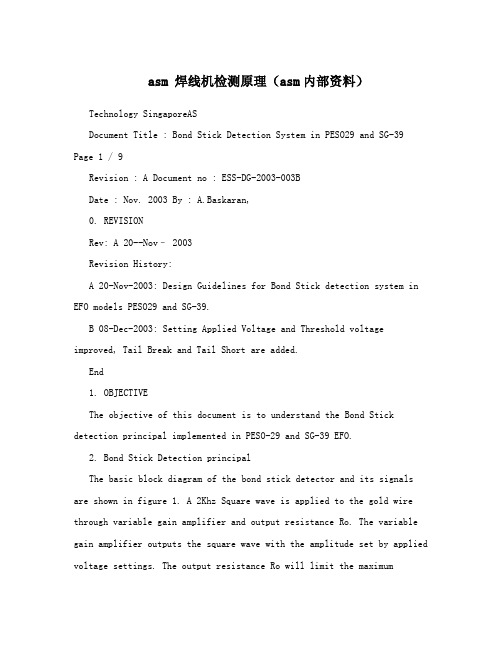
asm 焊线机检测原理(asm内部资料)Technology SingaporeASDocument Title : Bond Stick Detection System in PESO29 and SG-39 Page 1 / 9Revision : A Document no : ESS-DG-2003-003BDate : Nov. 2003 By : A.Baskaran,0. REVISIONRev: A 20--Nov– 2003Revision History:A 20-Nov-2003: Design Guidelines for Bond Stick detection system in EFO models PESO29 and SG-39.B 08-Dec-2003: Setting Applied Voltage and Threshold voltage improved, Tail Break and Tail Short are added.End1. OBJECTIVEThe objective of this document is to understand the Bond Stick detection principal implemented in PESO-29 and SG-39 EFO.2. Bond Stick Detection principalThe basic block diagram of the bond stick detector and its signals are shown in figure 1. A 2Khz Square wave is applied to the gold wire through variable gain amplifier and output resistance Ro. The variable gain amplifier outputs the square wave with the amplitude set by applied voltage settings. The output resistance Ro will limit the maximumpossible current to the die. The output resistance can be changed by the switch S1 and S2.During sparking the BS relay connects the gold wire to spark generator, during bonding the gold wire is connected to the Bond stick detector. Once the relay connects the bond stick detector to the gold wire the stray capacitance will come in to effect, that makes the voltage drop on the bond stick signal. The wiring to the gold wire and wire clamp capacitance forms this stray capacitance. The stray capacitance should be below 200pF typical value is 100pF. When the gold wire touch the die, depends on the die impedance the bond stick signal amplitude will drop further. If this amplitude is below the threshold voltage setting then the Bond stick detector output will report short other wise it will report open. ASM PROPRIETARY INFORMATION - NOT TO BE REPRODUCED OR COPIED WITHOUT WRITTEN PERMISSIONTechnology SingaporeASDocument Title : Bond Stick Detection System in PESO29 and SG-39 Page 2 / 9Revision : A Document no : ESS-DG-2003-003BDate : Nov. 2003 By : A.Baskaran,Figure 13. First Bond Stick Detection.The First bond stick is checked after the loop top before second bond. During this time Bond Stick detector output is expected to report short. If Bond Stick detector output is open then the stmachine may stop for 1 bond non-stick error. To detect short the Bond stick signal amplitude should drop below threshold voltage, once the gold wire touch the die.Successful first bond detection is mainly depends on selecting correct applied voltage, threshold voltage, current limit switch, dieimpedance and stray capacitance. Applied voltage and Threshold Voltage are set by DAC value, which can be calculated as voltage by this simple formula.Applied or Threshold Voltage = 5* (DAC /63) in Volts.In default set Applied Voltage = 40DAC (3.17V)Threshold Voltage = 11DAC (0.87V)ASM PROPRIETARY INFORMATION - NOT TO BE REPRODUCED OR COPIED WITHOUT WRITTEN PERMISSIONTechnology SingaporeASDocument Title : Bond Stick Detection System in PESO29 and SG-39 Page 3 / 9Revision : A Document no : ESS-DG-2003-003BDate : Nov. 2003 By : A.Baskaran,3.1 Output resistance switch settingPlease use this Table for selecting current limit switch,S2(Yellow) S1(Red) Output Maximum possible current Typical Remark resistance (Applied Volt = 63 DAC(5V) currentRo Stray capacitance = 0 pF.and Die impedance = 0 ohm)OFF OFF 1.14M? 4.38μA 1.5 μA Default ValueOFF ON 900K? 5.5 μA 2 μA Good for most of the DieON OFF 460 K? 10.8 μA 5 μA Good for discretedevicesON ON 220K? 22.7 μA 10 μA Good for LEDsTable13.2 Measuring Wire clamp and stray capacitanceStray capacitance can be estimated by measuring the Capacitance between White connector cable of EFO box to the Earth ground. Before measuring this capacitance make sure the following items.1. Gold wire threaded to the capillary.2. Switch OFF the machine,3. Capacitance meter should be set for Δ measurement, otherwise meter cablecapacitance may be more then 300pF.4. Remove the white connector from EFO box and insert one probe in to the connector onthe cable (not to the EFO box) and the other probe to the wing nut (Earth ground). Now measure the capacitance, by capacitance meter,multi-meters having capacitance measurement can be used for measuring this capacitance. The reading should be below 200pF, if higher or the meter not able to display any capacitor value then the wire clamp assembly has higher capacitance or short with ground.3.3 Setting Applied voltage and Threshold VoltageWith suitable Applied voltage and Threshold voltage only the bond stick detector can able detect first bond stick. The best and fast way to set this value is connect an oscilloscope and measure the Bond stick signal. Remove the white cable from PESO29 and remove the cap then connect the probe to the connector and connect the ground clip to thewing nut then put back the white connector to EFO. For SG39 connect the probe to wire spool connector. Set the oscilloscope time scale as10ms/div or 20ms/div and voltage scale as 0.5V/div or 1V/div. Set rising edge Trigger at 0.6V. Now set the parameters given in Table 2 –A1, (Applied voltage as 40, Threshold voltage as 12 and set switch S2= OFF & S1= OFF)3.3.1 Do single bond and capture the waveform. The waveform may look like the figure 2. (For theclarity purpose the waveform shown here is in lower frequency.)3.3.2 Measure V1 and V2 from the captured waveform, due to diode property some die may show theV1-V2 difference on one side may be higher than the other side. Take the higher difference ofV1-V2.3.3.3 Calculate Threshold Voltage (Vth) = (V1-V2)/2 + V2, Thisresult will be in volts now we have toconvert to DAC value using this formula. Threshold Voltage DAC = Vth * 63/5 3.3.4 Set this DAC value as Threshold voltage.ASM PROPRIETARY INFORMATION - NOT TO BE REPRODUCED OR COPIED WITHOUT WRITTEN PERMISSIONTechnology SingaporeASDocument Title : Bond Stick Detection System in PESO29 and SG-39 Page 4 / 9Revision : A Document no : ESS-DG-2003-003BDate : Nov. 2003 By : A.Baskaran,3.3.5 Incase (V1-V2 ) < 0.25V then set the next possible parameters given in Table2 (for eg. A2 nextA3 next B1 next B2 next … D3) and repeat the steps from 3.3.1. until getting the (V1-V2) >0.25V.Figure 2A B C DS2=OFF; S1=OFF S2=OFF; S1=ON S2=ON; S1=OFF S2=ON; S1=ON1 Applied Voltage Max Threshold Max Threshold Max Threshold Max Threshold= 40 DAC = 12 DAC = 14 DAC = 24 DAC = 30 DAC2 Applied Voltage Max Threshold Max Threshold Max Threshold Max Threshold= 50 DAC = 15 DAC = 18 DAC = 29 DAC = 36 DAC3 Applied Voltage Max Threshold Max Threshold Max Threshold Max Threshold= 60 DAC = 17 DAC = 21 DAC = 34 DAC = 39 DACTable 2If not possible to capture the Bond stick signal by oscilloscopethen to set suitable Applied andThreshold setting please follow the flow given in next page. Basedon the machine wire clamp capacitance specification (<200pf) the maximum allowableThreshold values are given in the Table 2 for each setting. ASM PROPRIETARY INFORMATION - NOT TO BE REPRODUCED OR COPIED WITHOUT WRITTEN PERMISSIONTechnology SingaporeASDocument Title : Bond Stick Detection System in PESO29 and SG-39 Page 5 / 9 Revision : A Document no : ESS-DG-2003-003B Date : Nov. 2003 By : A.Baskaran,Flow chart 1Set Switch S2= OFF; S1=OFFSet Applied Voltage = 40 DAC Threshold Voltage = 11 DACDo Single BondIs First bond No First Bond Stick parameters are set Non Stick False successfully alarmYesIncrease Threshold Voltage 1 stepIs Threshold No voltage > Max Threshold given inTable 2YesIncrease Applied Voltage 10 stepsNo Is Applied voltage > 60YesSet switch setting given in the next column of Table 2No Is all possible combinations are testedYesFirst Bond Non Stick cannot be detectedASM PROPRIETARY INFORMATION - NOT TO BE REPRODUCED OR COPIED WITHOUT WRITTEN PERMISSIONTechnology SingaporeASDocument Title : Bond Stick Detection System in PESO29 and SG-39 Page 6 / 9Revision : A Document no : ESS-DG-2003-003BDate : Nov. 2003 By : A.Baskaran,Based on the above flow diagram, it is possible to detect most common dies but some high impedance die with non-conductive epoxy ornon-conductive lead frame, it may not be possible to detect first bond. Some time if ground or substrate is bonded first then following pins may able to detect first bond. In some machines the wire clamp and stray capacitance value may be lower than 150pf, then the maximum threshold setting can be increased one more step to detect First bond.4. Second Bond DetectionFigure 3. Figure 4.The open status should occur before the Stick adjust time, otherwise machine may report Second Bond Non Stick. The open status is detected if the bond stick signal amplitude goes above the threshold value.Successful second bond detection is also mainly depends on selecting correct applied voltage, threshold voltage, current limit switch, die impedance, stray capacitance and stick adjust time. Stick adjust time is mainly depends on the stray capacitance, Bond head force and velocity.ndIt is not possible to detect second bond nonstick with nonconductive die. Since during 2 bond nonstick the signal current should go through the die, that reportshort for longer time than Stick adjust time ndthen it reported as 2 bond nonstick.Set the Applied voltage and Threshold voltage as per the section 3. and follow the steps given below.ASM PROPRIETARY INFORMATION - NOT TO BE REPRODUCED OR COPIED WITHOUT WRITTEN PERMISSIONTechnology SingaporeASDocument Title : Bond Stick Detection System in PESO29 and SG-39 Page 7 / 9Revision : A Document no : ESS-DG-2003-003BDate : Nov. 2003 By : A.Baskaran,4.1 Setting stick adjust timeStick adjust time very much depends on Z motion, second bond force, and elongation ofthe wire. Some time second bond surface, Wire clamp force, capillary edge are alsoaffects the stick adjust time. If not getting the consistent stick adjust time try to fine tunethe above parameters. For example if second bond force is not sufficient then the “v” cuton the wire may not have enough depth, then the wire may cut some time due toelongation and some time due to weak joint at “V” cut point.4.1.1 For setting the Stick adjust time enable Second bond stick detect and set the stick adjusttime to maximum. Then do single bond, the machine will report sick check sample value,note down this value for all the wire in that Die. Tack the maximum value, and add 3then set this value to stick adjust time.nd4.1.2 If 2 bond nonstick false alarm reported with stick check sample is always maximum ormore than the maximum Stick adjust time, then measure the wire clamp capacitance asper section 3.2. If it is greater than 200pf or short with ground then may replace wireclamp or check the wiring and remove the short.nd4.1.3 If 2 Bond false alarm occurs intermittent, and reportedstick check sample is little (3 to5 count) higher than the stick adjust time. Set the reported valueas Stick adjust time, set ndthe 2 bond parameter such that purposely 2nd bond nonstick will occur, then do single ndndbond. If 2 bond nonstick reported then set back the 2 bond parameter and continue. If not reported any error, then the wire may sleep through the wire clamp or the thresholdsetting is very marginal.4.1.4 To avoid any wire sleep through the wire clamp, calibrate the wire clamp force.4.1.5 To increase the threshold margin, may reduce the threshold voltage DAC by 1 count. Iffirst bond false alarm occur then do the flow given in flow chart 1 with next HigherApplied voltage or switch setting possibility given in the Table 2.4.1.6 If any change in Threshold voltage or Applied voltage again repeat from step 4.1.1. forsetting correct stick adjust time.5.Tail Break.If Tail break is enabled then the wire is cut slowly. During theTail break, instead of Stick Adjust time the Tail Stick parameter is used for detecting second bond stick, other than this there is no difference. For setting suitable Tail Stick parameter, follow the procedures given in section 4.1 and instead of setting stick adjust now set Tail Stick parameter.6.Tail Short.If the capillary force is high during the second bond the wire may cut before complete the second bond. That may cause OPEN state in detect out put earlier than wire clamp close.Stick Adjust time check for second bond is starts after wire clamp close and expected wire to break after wire clamp close. But if the wire break before wire clamp close then the following bond head movement, expected wire Tail may not appear outside of the capillary.Tail Short Time is counted before the wire clamp close. Tail too short is detected for the wire break before the Tail short time. Please see the Figure 5. for more detail.ASM PROPRIETARY INFORMATION - NOT TO BE REPRODUCED OR COPIED WITHOUT WRITTEN PERMISSIONTechnology SingaporeASDocument Title : Bond Stick Detection System in PESO29 and SG-39Page 8 / 9Revision : A Document no : ESS-DG-2003-003BDate : Nov. 2003 By : A.Baskaran,Figure 5.7. Measure the Bond stick signal current through the Die.We can measure the current through die with the help of oscilloscope. Remove the white cable from PESO29 and remove the cap then connect the probe to the connector and connect the ground clip to the wing net then put back the white connector to EFO. For SG39 remove the wire clamp connector and connect the probe into the connector. In oscilloscope we may get the waveform similar to the waveform shown in Figure 6. Measure the V1 and V2. Sometime due to diode action one side V1 -V2 difference may be higher than other side. Take the measurement on the higher difference side and use the formula shown below.Current through the die (I2) = (V1-V2) / R0.R0 can be estimated from the Table –1 as per switch setting.ASM PROPRIETARY INFORMATION - NOT TO BE REPRODUCED OR COPIED WITHOUT WRITTEN PERMISSIONTechnology SingaporeASDocument Title : Bond Stick Detection System in PESO29 and SG-39 Page 9 / 9 Revision : A Document no : ESS-DG-2003-003B Date : Nov. 2003 By : A.Baskaran,Figure 6.Figure 7.Figure 8.ASM PROPRIETARY INFORMATION - NOT TO BE REPRODUCED OR COPIED WITHOUT WRITTEN PERMISSION。
ASM焊线机参数指导
1A 0 /0 2 0 /2 16 Enc 100% 0 168 50% 5 Sm pl 50% E llip s e 4 4 5 /3 0
Scrub only applied to P Pad
ASM
Data
P Pad ball size &
thickness
Min Max Average
X (um) 78.32 74.53 75.8 75.8 77.9 74.53 78.32 76.47
74.90 77.90 76.61
78.30 83.80 81.44
12 14.5 13.20
N Pad Ball Shear (g)
M in M ax A ve ra g e
N Pad 7 5 .2 3 5 6 .7 6 6 1 .6 3 6 1 .5 5 6 8 .1 1 5 6 .7 6 7 5 .2 3 6 4 .6 6
3 /3 C o n s t P /C o n s t P
L o /L o M ode A
4000 725 35
58 384 48 2 0 /1 0 5 5 /5 0 4 5 /5 5
5 0 /0 2 0 /0 4 5 /0 5 5 /0
5 5 /0
1 0 /8
E n h a n c e r P a ra m e te r Enhancer M ode Enhancer Pow er E n h a n c e r tim e E n h a n c e r d e la y E n h a n c e r S td b yP o w e r E nhancer F1 E nhancer S 1 E nhancer S 2 E nhancer F2 E n h a n c e r C o n tro l M o d e
ASM 自动焊线机器介绍Au wire bonding rocess

Wafer Grinding
Wafer Saw
Die Bonding
Toaster
Wire Bonding
Die Surface Coating
Molding
Laser Mark
BGA
SURFACE MOUNTPKG THROUGH HOLE PKG
09.07.2020
Solder Ball Placement
Thermosonic bonding: utilizes temperature, ultrasonic and low impact force, and ball/ wedge methods.
Ultrasonic bonding: utilizes ultrasonic and low impact force, and the wedge method only.
Vibration (Power)
Al2O3
Moisture
09.07.2020
Al SiO2
Si Heat
ASM Pacific Technology Ltd. © 2009
page 15
Next to Gold Wire Bonder
09.07.2020
ASM Pacific Technology Ltd. © 2009
Dejunk Trim
Solder Plating
Singulation
Solder Plating
Forming/ Singulation
Trim/
Forming
ASM Pacific Technology Ltd. © 2009
Packing
page 5
Gold Wire Bonding
ASM焊线机参数指导-文档资料

CMLT Ball Size & Gold Remain Issue
- Smaller capillary CD
ATS WB Process
ASM
Material Background & Spec
Die source : Chi-Mei 14 x 17mil chip
Pad Opening : P Pad 94um, N Pad 92um
B a s e P a ra m e te r S ta n d b y p o w e r 1 /2 C o n ta c t tim e 1 /2 C o n ta c t P o w e r 1 /2 C o n ta c t F o rc e 1 /2
E n d fo rc e
R e fe re n c e P a ra m e te r S e a rc h h e ig h t 1 /2
Bonding Method : BSOB 2 wires
Device : 3020 18 columns x 8 rows
Ball shear spec : > 42g
Ball size spec : Max 85um
Gold remain spec : > 50%
Gold Wire : K&S AW99 1mil (EL 2-7% BL >9g)
3 /3 C o n s t P /C o n s t P
L o /L o M ode A
4000 725 35
58 384 48 2 0 /1 0 5 5 /5 0 4 5 /5 5
5 0 /0 2 0 /0 4 5 /0 5 5 /0
5 5 /0
ASM自动焊线机(ihawk)
ASM 自动焊线机简介目录一、键盘功能简介:21、键盘位置22、常用按键功能简介2二、主菜单(MAIN)介绍:3三、机台的基本调整:31、编程3①.设置参考点(对点)3②.图像黑白对比度(做PR)4③.焊线设定(编线)4④.复制5⑤.设定跳过的点5⑥.做瓷嘴高度(测量高度)及校准可接受容限(容差值)5⑦.一焊点脱焊侦测功能开关设定52、校准PR6①.焊点校正(对点)6页脚内容- 1 -②.PR光校正(做光)6③.焊线次序和焊位校正63、升降台的调整(料盒部位)6四、更换材料时调机步骤:61、调用程序62、轨道高度调整73、支架走位调整74、PR编辑(做PR)85、测量焊接高度(做瓷嘴高度)86、焊接参数和线弧的设定8①.时间、功率、压力设定8②.温度设定8③.弧度调整9④.打火高度设定9⑤.打火参数及金球大小设定9五、常见品质异常分析:101、虚焊、脱焊10页脚内容- 2 -2、焊球变形103、错焊、位置不当104、球颈撕裂105、拉力不足10六、更换磁嘴:10七、常见错误讯息:10八、注意事项11页脚内容- 3 -页脚内容- 4 -一、键盘功能简介:1、键盘位置:Wire Feed数字0—9 进行数据组合之输入移动菜单上下左右之光标Wire Feed 金线轮开关Thread Wire导线管真空开关Shift 上档键Wc Lmp 线夹开关Shift+Pan Lgt 工作台灯光开关EFO 打火烧球键Inx 支架输送一单元Shift+IM↑左料盒步进一格Main 直接切至主目录Shift+IM↓左料盒步退一格Shift+IM HM 换左边料盒Shift+OM↑右料盒步进一格Shift+OM↓右料盒步退一格Ed Loop 切换至修改线弧目录Shift+OM HM 换右边料盒Chg Cap 换瓷咀Shift+Clr Tk 清除轨道Bond 直接进入自动作业画面Dm Bnd 切线Del. 删除键页脚内容- 5 -Stop 退出/停止键Enter 确认键Shift+Ctct Sr 做瓷咀高度Ld Pgm 调用焊线程序二、主菜单(MAIN)介绍:0.SETUP MENU (设定菜单)Array 1.TEACH MENU (编程菜单)2.AUTO BOND (自动焊线)3.PARAMETER (参数)4.WIRE PARAMETER (焊线参数)5.SHOW STATISTICS (显示统计资料)6.WH MENU (工作台菜单)7.WH UTILITY (工作台程序)8.UTILITY (程序)9.DISK UTILITY (磁盘程序)三、机台的基本调整1、编程:当在磁盘程序〈DISK UTILITIES〉中,无法找到所需适用的程序时,就必须重新建立新的程序,在新编程序之前必须将原用程序清除掉(在MAIN——1.TEACH——5.Delete Program——A——STOP),方可建立新程序。
ASM自动焊线机(ihawk)
ASM 自动焊线机简介目录一、键盘功能简介:21、键盘位置22、常用按键功能简介2二、主菜单(MAIN)介绍:3三、机台的基本调整:31、编程3①.设置参考点(对点)3②.图像黑白对比度(做PR)4③.焊线设定(编线)4④.复制5⑤.设定跳过的点5⑥.做瓷嘴高度(测量高度)及校准可接受容限(容差值)5⑦.一焊点脱焊侦测功能开关设定52、校准PR6①.焊点校正(对点)6②.PR光校正(做光)6③.焊线次序和焊位校正63、升降台的调整(料盒部位)6四、更换材料时调机步骤:61、调用程序62、轨道高度调整73、支架走位调整74、PR编辑(做PR)85、测量焊接高度(做瓷嘴高度)86、焊接参数和线弧的设定8①.时间、功率、压力设定8②.温度设定8③.弧度调整9④.打火高度设定9⑤.打火参数及金球大小设定9五、常见品质异常分析:101、虚焊、脱焊102、焊球变形103、错焊、位置不当104、球颈撕裂105、拉力不足10六、更换磁嘴:10七、常见错误讯息:10八、注意事项11一、键盘功能简介:1、键盘位置:Wire Feed2、常用按键功能简介:数字0—9 行数据组合之输移动菜单上下左右之光标Wire金线轮开Thread导线管真空开关 Shift 档Wc 线夹开关Shift+Pan工作台灯光开EFO 打火烧球键Inx支架输送一单Shift+IM ↑ 料盒步进一格Main 接切至主目Shift+IM ↓ 料盒步退一格Shift+IM HM 换左边料盒 Shift+OM ↑ 右料盒步进一格 Shift+O M ↓ 右料盒步退一格 Ed Loop 切换至修改线弧目录 Shift+OM HM 换右边料盒 Chg Cap 换瓷咀Shift+Clr Tk 清除轨道 Bond 直接进入自动作业画面 Dm Bnd 切线 Del. 删除键 Stop 退出/停止键 Enter 确认键 Shift+Ctct Sr 做瓷咀高度 Ld Pgm 调用焊线程序二、主菜单(MAIN )介绍:0.SETUP MENU (设定菜单) 1.TEACH MENU (编程菜单) 2.AUTO BOND (自动焊线) 3.PARAMETER (参数) 4.WIRE PARAMETER (焊线参数) 5.SHOW STATISTICS (显示统计资料)6.WH MENU (工作台菜单)7.WH UTILITY (工作台程序)8.UTILITY (程序)9.DISK UTILITY (磁盘程序)三、机台的基本调整1、编程:当在磁盘程序〈DISK UTILITIES〉中,无法找到所需适用的程序时,就必须重新建立新的程序,在新编程序之前必须将原用程序清除掉(在MAIN——1.TEACH——5.Delete Program——A——STOP),方可建立新程序。
ASM自动焊线机培训
自动焊线机培训目录一、键盘功能简介:............................................................. - 2 -1、键盘位置: ............................................................... - 2 -2、常用按键功能简介: ....................................................... - 2 -二、主菜单( MAIN )介绍:....................................................... - 3 -三、机台的基本调整............................................................... - 3 -1、编程: ................................................................... - 3 -2、校准 PR (重做图像): .................................................. - 5 -3、升降台的调整(料盒部位): ............................................. - 6 -四、更换材料时调机步骤:......................................................... - 6 -1、调用程序 : ............................................................... - 6 -2、轨道微调: ............................................................... - 6 -3、支架走位调整: ........................................................... - 7 -4、PR 编辑(改 PR): ....................................................... - 7 -5.测量焊接高度(做瓷嘴高度): ........................................... - 7 -6、焊接参数和线弧的设定 : ................................................... - 7 -(1)设定线弧模式....................................................... - 7 -(2)设定基本焊接参数................................................... - 8 - 五:常见品质异常分析:........................................................... - 9 -1、虚焊、脱焊: ............................................................. - 9 -2、焊球变形: ............................................................... - 9 -3、错焊、位置不当: ......................................................... - 9 -4、球颈撕裂: ............................................................... - 9 -5、拉力不足: ............................................................... - 9 -6、断线 ..................................................................... - 9 -六、更换磁嘴:................................................................... - 9 -七、常见错误讯息:.............................................................. - 10 -八、注意事项:.................................................................. - 10 -1、................................ 温度设定:220C -350 C之间(一般设定为2 8 0 C)-10 .......................................................................... -2、.......................................................................... 在AUTO BOND MENU 下必须开启之功能:................................................ - 10 -3、保持轨道清洁,确保送料顺畅。
- 1、下载文档前请自行甄别文档内容的完整性,平台不提供额外的编辑、内容补充、找答案等附加服务。
- 2、"仅部分预览"的文档,不可在线预览部分如存在完整性等问题,可反馈申请退款(可完整预览的文档不适用该条件!)。
- 3、如文档侵犯您的权益,请联系客服反馈,我们会尽快为您处理(人工客服工作时间:9:00-18:30)。
关于A S M焊线机的一些个人心得
一、首先你得搞懂焊线机焊线时,焊头是如何移动的。
二、线弧是如何拉扯形成的。
三、明白怎么机器是怎么动的以后,你得明白哪些参数控制哪些动作,能达到什么效果。
四、深度熟悉焊线机页面后,你就会知道焊线有哪几种模式,如(bbos bsob 切线)等,线弧有哪几种模式,三角线弧,梯形线弧,反打线的线弧等,编程时矩阵有哪些模式,焊头如何移动等。
五、参数都是搭配起来使用的,(焊线时间,焊线功率,焊线压力)一般功率会大于或等于压力15个单位,(接触时间,接触压力,接触功率,是焊线动作前的控制参数)另外还有初始压力等。
六、焊线时遇到的一些问题:断线是经常遇到的,首先你可以确定是否是外部因素造成的,如瓷嘴,金线污染,压板支架不平,是否要吹氮气等,后面再去找参数原因,最后搞清洁瓷嘴,线夹等。
七、二焊球形,如何才能结合的好,不是功率越大,压力越大,结合的越好,要看温度,球形参数的调节,这个要靠个人经验,二焊球形参数不匹配还会造成断线。
八、线弧的调节,你要明白线弧是如何拉扯出来的,反转角度的正负值是什么意思,正值是焊头如何动作,负值时焊头如何动作,反转角度±25度之间,太大或太小,都会造成线弧颈部受损。
九、如何加快焊线速度:可以调搜索速度,搜索高度,瓷嘴高度,进出料时间,压板停留时间,预热版温度,各种参数延迟等。
十、保持一个谦虚学习的心,明白原理再去多多实践,设备工程师没有什么难的。
