SB3042-Ex使用手册
中控仪表产品介绍
SB3075-Ex
导轨安装
大客户及业绩
� � � � � � � � � 武汉钢铁股份有限公司(亚洲最大焦炉项目) 20000 只以上 湖北三宁化工有限公司(国家 4060项目 ) 2000 只以上 湖北当阳华强化工有限公司 6000 只以上 神木锦界天元化工有限公司 2000 只以上 中海石油宁波大榭石化有限公司 1000 只以上 宁波科元塑胶有限公司( 7万吨/年溶液丁苯橡胶( SBS)联合装置) 浙江新安迈图有机硅有限公司 1500 只以上 杭州奥通科技(新疆新澳特种纤维有限公司) 1000 只以上 四川空分设备(集团)有限责任公司 1000 只以上 ……
产品外观
-Ex 系列隔离栅分类 SB3000 SB3000-Ex -Ex系列隔离栅分类
- Ex x 1 3 0 3 AI : 3041/42-E x AI : 3045/46-E AO: 3043-Ex AI :
按信号转换方式区分
信号复
制
运算变换
动作判
温度型:3073-Ex 温度型:3075-Ex
本质安全的概念
� 本安系统的构成是由安全栅和现场本安设备构成,各司 一职,共同作用
� 本安设备
� 安全栅
火花安全
能量限制
式安全 栅内部结构划分 隔离 隔离式安全 式安全栅内部结构划分
危险侧 安全侧 DCS系统
仪表回路
电源端
SB3000 -Ex 系列隔离 式安全 栅型号 SB3000-Ex -Ex系列隔离 系列隔离式 安全栅型号 (去掉 EX 代码可做隔离栅使用) (去掉EX EX代码可做隔离栅使用)
记录仪
R1000 F1000 C1000
R3000/4000 C6000 AR 3000/4000 AR3000/4000
浙大中控安全栅SB3042-Ex使用手册
ATTENTION: Identifies information that requires special consideration.
提示:标记对用户的建议或提示。 TIP:Identifies advice or hints for the user.
2
SB3042-Ex使用手册
防止静电:标示防止静电损坏设备的信息。
ESD HAZARD: Indicates information that Danger of an electro-static discharge to which equipment may be sensitive. Observe precautions for handling electrostatic sensitive d级 配电输出电源 输出信号范围 信号输出特性 转换精度 温度漂移 数字信号带宽 供电电源 隔离电压
安全参数
适用的现场设备
表 2-1 性能指标
SB3042-Ex
1 现场的设备经过适当认证后,可使用于 0 区、ⅡC、T4-T6 的危险场所 输出电流 20mA 时,配电电压大于 16.5V DC *注:配电回路开路时,最大配电电压为 28V DC (4~20)mA 负载能力:(0~650)Ω 输出纹波:峰峰值小于 40μA 响应时间:20ms 以内达到最终值的 90%
工业自动化-花落忆无声
目录
隔离式安全栅 SB3042-Ex.............................................................................................................................. 1 1 基本说明..................................................................................................................................................... 1 2 性能指标..................................................................................................................................................... 1 3 使用说明..................................................................................................................................................... 2 4 资料版本说明............................................................................................................................................. 2
SB200, SB210, SB220 手指型 Pulse Oximeter 使用說明書说明书
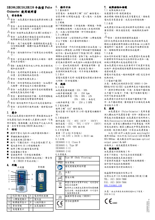
SB200,SB210,SB220手指型Pulse Oximeter 使用說明書1.安全指南警告:血氧濃度計須由受過專業訓練人員操作。
警告:在有易燃性麻醉劑或是易燃性氣體存在時,請勿使用,以免爆炸。
警告:勿使用血氧濃度計在MRI的環境下。
警告:血氧濃度計讀值易受到某些環境、施用錯誤或是病患狀況影響。
警告:爲了避免電擊,請僅開啟電池盒蓋,切勿開啟機體,機體只能由專業服務人員拆解。
警告:請勿操作於如下雨等高水分的環境下。
警告:若是無法確定量測之正確性,請用其他方法確認。
警告:本機是用來作病人評估,配合臨床訊號和症狀使用。
警告:長時間使用需要每4小時更換施用位置,並定期檢視病患狀態。
警告:勿使用在嬰兒身上。
警告:任何會限制血流的場合,如血壓計之腕帶,將會造成不正確的量測值。
警告:血氧濃度計之操作易受到週遭強電磁源或是強光源的干擾。
警告:量測時請保持平穩,長時間運動後或是劇烈晃動易影響量測準確度。
警告:請勿使用於手指以外或是受傷部位。
警告:若長時間不使用本機,請將電池卸下。
2.簡介手指式血氧濃度計提供即時、單點量測血液中含氧濃度(SpO2)和無侵入式量測心跳率。
可使用於醫院、醫療機構、或是家庭中之成人和兒童。
並有警告功能(SB200無此功能)。
3.特性⏹提供可靠之SpO2和心跳率量測和顯示。
⏹單鍵啟動快速操作。
⏹高亮度有機LED顯示。
⏹輕巧,可攜式設計。
不包含電池僅37克。
⏹電池壽命約16小時連續使用。
⏹使用2顆AAA鹼性電池供電⏹低電量顯示警告。
⏹當無使用時,8秒後自動關機。
⏹警告符號功能(SB200無此功能),聲音警告(SB220方有此功能)。
4.外觀5.操作方法5.1基本操作安裝電池- 本機使用2顆”AAA”鹼性電池。
安裝步驟-打開電池盒蓋,裝入電池,注意極性標示。
5.2開機按下開關機按鍵,1秒後啟動。
開機後,即顯示軟體版本號碼。
之後系統進入自我測試模式。
之後心型符號閃爍,即可開始量測。
5.3心搏偵測當有待測者,心型符號停止閃爍,心博強度顯示上下變動,表示量測即將顯示。
安全栅信号隔离器

4.5
0.58 0.66
-0.66
-0.66
-0.66 0.66 0.35 0.096 0.25 0.35 0.096 0.25
电缆参数 Cc 和 Lc 应满足下列条件: Cc≤CO - Ci;Lc≤LO - Li 仪表中未经保护的电容 Ci 和电感 Li 由防爆检测机
构在认证仪表时予以给出。 表 2 中所列的数值表示用于ⅡC 气氛中,其最大
Lc — — 本 安 仪 表 与 安 全 栅 的 连 接 电 缆 的 分 布 电 感。
若采用参量认可,用户在进行本安系统设计时,
只需比较关联设备和本安设备的整体参数。当它们满
足表 1 中所列关系式时,就可以构成本安系统:
表 1 参量认可本安系统条件
本安仪表参数及电 缆参数
安全参数匹配条件
隔离栅参数
Ui
4
SB3000-Ex 系列隔离式安全栅
选型一览表
开关量输入
产品型号
SB3016/R-Ex
SB3016/OC-Ex
通道数 2
现场输入类型
触点开关、NAMUR 型接近开关等
电压脉冲、触点开关、接近开关、流 量计等
输出类型 2 对继电器常开或常 闭触点
OC 门输出
备注 (0~20)Hz , 施 密 特,开关阀值可调
2-3 1-2 1-2 6-4-5 4-5 6-5 6-4-5 4-5 6-5
电缆选用
安全栅的最大允许负载参数是最大允许电容 CO 和最大允许电感 Lo。用户须根据所选用安全栅的最大 外部电容 CO,最大外部电感 Lo 和现场本安设备最大内 部电容 Ci,最大内部电感 Li,参照表 3~表 5,将所选 用电缆每千米的分布电容值 Kc 和电感值 Ki 按 1.1 和 1.2 式来进行计算,取其小者。
高频微型同步漏电保护电源芯片说明书

1.8
1.4
Normalized VGS(th)
1
0.6
0.2 -50
0
50
100
150
TJ ,Junction Temperature (℃ )
Fig.5 Normalized VGS(th) vs. TJ
Normalized On Resistance
VGS , Gate to Source Voltage (V)
0.027 9 9.6 0.85
-5.8 ------40 0.9 16 2.8 3.7 12 10 24 5.5 1150 120 85
Max. ----10.8 12 1.3 --1 5
±100 --2.0 21 3.5 4.4 18 15 40 8 -------
Unit V
V/℃ mΩ V mV/℃ uA nA S Ω
T ON T
D = TON/T TJpeak = TC+PDMXRθJC
0.1
ห้องสมุดไป่ตู้1000 1
Fig.9 Normalized Maximum Transient Thermal Impedance
Normalized Thermal Response (RθJC)
Fig.10 Switching Time Waveform
The WSD3042DN56 meet the RoHS and Green Product requirement , 100% EAS guaranteed with full function reliability approved.
SB3045-Ex使用手册
电击危险:标示有可能产生电击危险的信息。
Risk of electrical shock: Indicates information that Potential shock hazard where HAZARDOUS LIVE voltages greater than 30V RMS, 42.4V peak, or 60V DC may be accessible.
电流(传输 20mA 时) :
供电电源
60mA(20V 供电时) 50mA(24V 供电时) 40mA(35V 供电时)
功率:1.2W(24V 供电,20mA 输出时) 安全侧和危险侧隔离电压 250V AC/DC 国家仪器仪表防爆安全监督检验站 NEPSI 认证参数(防爆合格证号: GYB071211) 端子 1-2: Uo=28V,Io=93mA,Co=0.083μF,Lo=4.2mH,Po=0.66W 电/气转换器 阀门定位器等
隔离式安全栅
45 -Ex 使用手册 SB30 SB3045 45-Ex
浙江中控技术股份有限公司
声
� �
�
明
严禁转载本手册的部分或全部内容。 在不经预告和联系的情况下,本手册的内容有可能发生变更,请谅解。 本手册所记载的内容,不排除有误记或遗漏的可能性。如对本手册内容有疑问,
请与我公司联系。
文档标志符定义
4 资料版本说明
表 4-1 版本升级更改一览表 资料版本号 SB3045-Ex 使用手册(V1.0) 适用产品型号 SB3045-Ex 更改说明
2
பைடு நூலகம்
表 2-1 性能指标 型号 通道数 现场设备防爆等级 工作范围 信号输出特性 转换精度 温度漂移 SB3045-Ex 1 现场的设备经过适当认证后,可使用于 0 区、ⅡC、T4-T6 的危险场所 (4~20)mA 负载能力: (0~600)Ω *注:当负载为 600Ω/20mA 时,能输出电压 12V。 输出纹波:峰峰值小于 40μA 响应时间:60ms 以内达到最终值的 90% 优于±16μA 优于±1μA/℃ 电压:(20~35)VDC
SB3041-Ex使用手册
SB3041-Ex 使用手册
41 -Ex 隔离式安全栅 SB30 SB3041 41-Ex
1 基本说明
SB3041-Ex 电流输入型隔离式安全栅为现场 2/3 线制变送器提供一组隔离的供电电源, 并将现场 的(4~20)mA 电流信号转化成(4~20)mA 或(1~5)V 信号隔离复制到输出端。
2 性能指标
警告:标示有可能导致人身伤亡或设备损坏的信息。
WARNING: Indicates information that a potentially hazardous situation which, if not avoided, could result in serious injury or death.
防止静电:标示防止静电损坏设备的信息。
ESD HAZARD: Indicates information that Danger of an electro-static discharge to which equipment may be sensitive. Observe precautions for handling electrostatic sensitive devices
电击危险:标示有可能产生电击危险的信息。
Risk of electrical shock: Indicates information that Potential shock hazard where HAZARDOUS LIVE voltages greater than 30V RMS, 42.4V peak, or 60V DC may be accessible.
4 资料版本说明
表 4-1 版本升级更改一览表 资料版本号 SB3041-Ex 使用手册(V1.0) 适用产品型号 SB3041-Ex 更改说明
希捷CP-X3042WN LCD投影机说明书
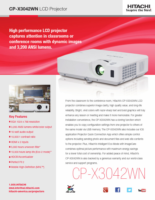
Key Features■ X GA 1024 x 768 resolution■ 3,200 ANSI lumens white/color output ■ 16 watt audio output ■ 10,000:1 contrast ratio ■ H DMI x 2 inputs■ 5,000 hours unwoven filter*■ 10,000 hours lamp life (Eco-2 mode)**■ HDCR/Accentualizer ■ P erfect Fit 2■ M obile High-Definition (MHL™)CP-X3042WNFrom the classroom to the conference room, Hitachi’s CP-X3042WN LCD projector combines superior image clarity, high quality value, and long-life reliability. Bright, vivid colors with razor-sharp text and bold graphics will trulyenhance any lesson or meeting and make it more memorable. For greater installation convenience, the CP-X3042WN has a cloning function which enables you to copy configuration settings from one projector to others of the same model via USB memory. The CP-X3042WN also includes our iOS application Projector Quick Connection App which offers simple control options including sending photo and document files and web site contents to the projector. Plus, Hitachi’s Intelligent Eco Mode with ImageCare combines optimal picture performance with maximum energy savings for a lower total cost of ownership. For added peace of mind, Hitachi’s CP-X3042WN is also backed by a generous warranty and our world-class service and support programs.PC-Less PresentationBy using a USB memory stick or other storage device, you can use the projector without a computer. Menus are easy to see with a thumbnail display. There is also a slideshow function. This feature also supports the following file types: JPG, PNG, BMP , GIF, AVI, and MOV — frame rate is under 12fps 640 x 480.PIN Lock / MyScreen / MyTextPIN lock protection can limit projector users. MyScreen PIN lock keeps captured images on the startup screen. Users can set any name logo to MyScreen, clearly identifying ownership. MyText provides the ability to write text on the startup screen such as model name, serial number or location.PJMessengerPJMessenger function allows you to send and display text messages and audio alerts on your networked projectors. It is an easy and efficient way to send announcements out tomultiple units.Present Content via LANHitachi’s suite of networking software allows you to easily send content directly from your PC to the projector via yourLAN connection.Serial Number and Media Access Control LabelA label is affixed to side of projector to more easily access and read the model name, serial number and MAC address while mounted in ceiling use. This is a convenience for installers, end users and auditors for instant accessibility. Serial #Wireless Presentation CompatibleConnect the projector to a computer or your network using the optional USB wireless adapter (part number USBWL11N).The adapter supports IEEE802.11n.STANDARD FEATURES Network Control, Maintenance and SecurityEmbedded networking gives you the ability to manage and control multiple projectors over your LAN. Features include scheduling of events, centralized reporting, image transfer and e-mail alerts for reactive and routine maintenance.Microphone InputA microphone can be used via the jack located on theinput panel. Allows for more dynamic presentations even instandby mode.Users can rename input sources in more descriptive terms Input Source Naminginstead of the factory default names.UNIQUE FEATURES Cloning FunctionCopy configuration settings from one projector to others of the same model via USB memory. Cloning can save almost all PJ settings such as gamma and keystone via USB memory.settingssettings Intelligent Eco and Saver ModesAutomatically changes the brightness of the lamp according to the brightness level of the screen. Also, automatically changes the brightness of the lamp if there is no change in the screen image. Using ImageCare technology, these features give optimal picture performance with maximum energy savings.ImageCare TechnologyImageCare is a lamp power control function that combines optimal picture performance with maximum energy savings by decreasing energy usage, improving contrast ratio and lengthening lamp life. The result is a lower total cost of ownership and decreased maintenance cost.Projector Quick Connection App For Mobile DevicesOur iOS application offers full projector control and alsoprovides the capability to display photos, document files and web site contents. Available for iPad ®, iPhone ® and Android devices. Works over your LAN via your RJ-45 port or via an optional USBWL11N wireless adapter.HDCR (High Dynamic Contrast Range)When average projectors are used in bright rooms, the darker colors of an image deteriorate and images become unclear. Using this function, blurred images caused by room lighting or outside light sources are corrected, and an effect similar to increasing contrast occurs. This results in clear images even in bright rooms.AccentualizerHitachi original technology makes pictures look more real by enhancing sharpness, gloss and shade to make pictures as clear as pictures on a flat-panel device. You can also adjust the effects by three levels according to your surroundings so that the colors of projected images are the actual colors of the objects they represent.Sharpness Gloss ShadePerfect Fit 2Enables the user to adjust individual corners and sides independent of one another. Perfect Fit 2 provides vertical and horizontal digital correction of either barrel or pincushion distortions. This feature helps correct geometric and complicated distortions. Perfect Fit 2 allows the projected image to fit correctly to the screen quickly and easily. UNIQUE FEATURES Cont'd Wireless Switcher SolutionsMultifunctional switcher operates in conjunction with the receiver to provide expanded source selection and switching options for connected devices. The switcher is sold as an optional accessory that can provide 1080p 30 fps wireless via WHDI for both video and audio.MHL™MHL (Mobile High-Definition) allows users to mirror their phone/tablet screen with the projector display. It is compatible with any and all apps.the CP-X3042WN features high contrast ratio, long lamp life, cloning function enabling you to copy configuration settings from one projector to others of the same model, and is wireless presentation compatible. Plus, embedded networking gives you the ability to manage and control multiple projectors over your LAN (scheduling of events, centralized reporting, image transfer, and e-mail alerts). Even with the the array of advanced features, Hitachi’s CP-X3042WN is designed for user-friendly operation and installation convenience.Left ProfileRight Profile Front ViewInput/Outputs54。
奥比诺克斯 EX 型刀片闸阀 技术手册说明书

• Pulp and Paper • Wastewater treatment plants • Food and Beverage • Mining • Power plants• Chemical plants• Bulk handling• Etc.Working pressure:Reserves the right to change specifications without noticeDN 50 to DN 250DN 300 to DN 400 DN 450DN 500 to DN 600 DN 700 to DN 1200All valves are tested prior to shipping in accordance with the standard developed by the Quality Control Department at ORBINOX.Other flange connections available on requestSizes: DN 50 to DN 1200 (larger diameters on request) Standard flange connection:DIN PN 10 and ANSI B16.5 (class 150)DIN PN 6 BS “D” and “E” DIN PN 25DIN PN 16 ANSI 125Directives:STANDARD PARTS LISTFor EU Directives and other Certificates please see the document: Directives & Certificates Compliance - Knife Gate Valves – Catalogues and Datasheets10 bar 6 bar 5 bar 4 bar 2 barOBX 05/21The EX model knife gate is an uni-directional wafer valve designed for general industrial service applications. The design of the body and seat assures non-clogging shut off on suspended solids in industries such as:Unique design that mechanically locks the seal in the internal of the valve body with a stainless steel retainer ring. Standard EPDM also available in different materials such as Viton, PTFE, etc.PACKING:Long-life packing with several layers of braided fibre plus an EPDM o-ring, with an easy access packing gland ensuring a tight seal. Long-life braided packing is available in a wide range of materials. The standard stainlesssteel stem offers a long corrosion resistant life. For rising stem handwheel actuators only, a stem protector is provided for additional protection against dust while the valve is in the open position. STEM: ACTUATORS:YOKE or ACTUATOR SUPPORT:EPOXY COATING:The epoxy coating on all ORBINOX cast iron and carbon steel valve bodies and components isapplied by means of an electrostatic process, making the valves corrosion-resistant with a high quality finished surface.The ORBINOX standard colour is RAL-5015 blue. ORBINOX automated valves are provided with gate guards in accordance with EU SafetyStandards. The design feature prevents any objects from being caught accidentally while the gate is moving.Made of EPOXY coated steel (stainless steel available on request). Compact design makes it extremely robust even under the most severe conditions. All actuators supplied by ORBINOX are interchangeable, and supplied with a standard mounting kit for installation purposes on site. GATE SAFETY PROTECTION:DESIGN FEATURESBODY:Wafer style cast monoblock with raised faces and reinforcing ribs in large diameters for extra body strength. Internal cast-in gate wedges and guides allow for a tighter shut-off between gate and seat. Full port design for greater flow capacity and minimal pressure drop. The internal body design avoids any accumulation of solids that would prevent the valve from closing. GATE:Stainless steel gate. Gate is polished on both sides to avoid jamming and seat damage. Bottom of the gate edge is machined to a bevel to cut through solids for a tighter seal in the closed position. The thickness and/or material of the gate can be changed on request for higher pressure requirements. SEAT: (resilient)Flush ports (Fig.2):Allow for cleaning of solids trapped within the body cavities that can obstruct the flow or prevent the valve from closing. Depending on the process, purging can be made with air, steam, liquids, etc.Other materials of construction:Ductile iron, carbon steel, stainless steels (AISI 317, ...), special alloys(254SMO, Hastelloys, …), etc.ORBINOX designs, produces and delivers special fabricated valves for special process conditions (big sizes and/or high pressures).EXT (full lug design):Modified version of the EX model with full lug design for end of lineapplications. Standard flange connection from DIN PN 10, ANSI 150, to AS "D". Sizes available up to DN 600. Fig.1OTHER OPTIONS Bonnet (Fig.1):Assures tight sealing to atmosphere.Reduces packing maintenance.V-port:60 degree and pentagonal port design. Selection depends on the desired fluid control type.Fig.2SURFACE TREATMENTSValve components can be protected or coated for a longer life expectancy, depending on the application of the valves and the valve service conditions. At ORBINOX we can offer alternative treatments and coatings for the different valve components to improve their properties against abrasion (Stellite, Polyurethane…), against corrosion (Halar, Rilsan, Galvanised…) and against adherence (Polishing, PTFE…).We recommend to contact our technical department.Fabricated valves:Wide range of valve extensions availablePlease contact our Technical DepartmentStandard Handwheel (Rising Stem)Handwheel (Non Rising Stem)ElectricLeverACTUATOR TYPESMANUAL:Handwheel (rising stem) Handwheel (non-rising stem) Chainwheel LeverBevel GearOther (square nut)AUTOMATIC:Electric (rising & non-rising stem) Pneumatic (single & double-acting) HydraulicAll actuators supplied by ORBINOX are interchangeableACCESSORIES: Mechanical StopsActuator manual override PositionersProximity Switches Stem ExtensionsLocking device Solenoid valves Limit Switches Floor standsPneumatic Cylinder>250 120 120200 250 250SEAT TYPESMETAL/METALFor applications with: • High temperature• High density media application • In those cases when full tightness is not requiredRESILIENT TYPE "A" • Standard resilient seat.• Temperature limitations according to the selected seat material. Review the above chart or contact our Technical Department for more information.• Seat with replaceable retainer ringTYPE "B" SEAT (metal/metal) For applications with: • High temperature• High density media application • In those cases when full tightness is not required • Replaceable design without disassembling the valveNOTE: all types include an elastomere O-ring (same material as seal), excluding TH, GR and FC.pH2502-13 260 0-14 600 0-14 1200--TYPE "B" SEAT (resilient)• Temperature limitations according to the selected seat material. Review the above chart or contact our Technical Department for more information.• Replaceable and reinforced seat ring available in different materials such as: stainless steel, CA1 5, Ni Hard,…DEFLECTION CONE "C"• Deflects the media away from any valve internal exposed parts (gate, seat, .)• Material: AISI 316, CA15, Ni -Hard, etc. • Face -to-face dimension increases: DN 50 to DN 250 X = 9mm DN 300 to DN 600 X = 12mm Larger diameters on requestMore details and other materials under request Metal/MetalEPDM (E)NBR (N)FKM-FPM (V)VMQ (S)PTFE (T) High temp./Low tightness Acids and non mineral oilsResistance to petroleum productsChemical service/High temp.Food service/High temp.Corrosion resistance TEMPERATURE CHARTSEAT / SEALSPACKINGMaterialMax.T (ºC) MaterialApplicationsMax.T (ºC)PTFE impregn. synth. fibre (ST)Braided PTFE (TH)Graphited (GR)Ceramic fibre (FC)VALVE EXTENSIONSThe extension on a valve allows the operator to open or close the valve from a distance. Different types of extensions can be used depending on the application and the distance from the gate to the actuator.1- Floor stand• A pipe of the required length is added to the valve stem.• Stem and yoke assembly remain in the original position.• A floor stand is normally used at the top of the extension for actuator installationpurposes.• Required dimensions:H1: distance from centre line of the pipe to the base of the floor.d1: (wall bracket) distance from the wall to the face of the connecting flange.Notes:Fig.1Fig. AFig.2a- Any type of actuator can be mounted on the floor stand such as Handwheel, Gear,Electric, etc.b- A wall bracket (Fig. A) is recommended at every 1.5m. This prevents any deviation orbuckling of the extension rod.c- Standard construction of the floor stand is fabricated carbon steel. Other materials areavailable on request. (Fig. 1)d- A position indicator (optional) can be installed for easy visibility of the percentage ofopening of the valve.e- Availability of supports for actuator floor stands (Fig. 2) upon request.2- Tube• Stem and yoke assembly remains in its original position.• Handwheel is replaced by a tube, which rotates at the time of operating the valve.• Stem rises and lowers within the tube.• Ideal for surface box operation, valve can be operated with a T-bar and a square nut.• Required dimensions:H1: distance from centre line of the pipe to the base of the floor.d1: (wall bracket) distance from the wall to the face of the connecting flange.a- Handwheel or square nut operated only.b- A wall bracket (Fig. A) is recommended at every 1.5m. This prevents any deviation or buckling of the extension rod.c- Standard construction of the extension is carbon steel epoxy coated. Other materials are available on request.3- Universal joint 4 - Extended support plates• Universal joints are used in those cases where the alignment of the extension between valve and actuator is not feasible.• Please contact our technical department for more information. • Ideal where long extensions are not required.• Guide bearing is installed at the mid point to prevent any deflection of the rod.Notes:HANDWHEEL (rising stem)• Standard manual actuator• Consists of:- Handwheel: Epoxy coated Cast Iron - Stem- Stem nut- Stem protector• Available from DN 50 to DN 1000• Options:- Locking Device- ExtensionsDN A B C D E F ØG H50 40 119 100 105 129 47 225 420 7 65 40 134 100 115 146 47 225 450 8 80 50 149 100 124 162 47 225 475 9 100 50 169 100 140 187 47 225 520 11 125 50 180 100 150 211 47 225 600 15 150 60 210 100 175 237 47 225 652 18 200 60 262 119 205 309 67 310 822 30 250 70 318 122 250 364 67 310 1022 44 300 70 372 122 300 414 67 310 1122 58 350 96 431 197 338 486 66 410 1323 96 400 100 486 197 392 536 66 410 1427 124 450 106 540 201 432 588 66 550 1594 168 500 110 602 201 485 648 66 550 1707 192 600 110 708 201 590 748 66 550 2022 245 700 110 834 380 686 890 74 800 2778 405 750 110 884 380 760 945 74 800 2900 455 800 110 1015 320 791 989 74 800 2980 512 900 110 1040 320 895 1118 74 800 3215 680 1000 110 1146 320 975 1220 74 800 3400 865Weight (kg.)• Recommended for installation where space is limited.• Consists of:- Handwheel- DN 50-300: Aluminium- DN ≥ 350: GJS400 (GGG40)- Stem- Yoke bushing- Stem nut fixed to the gate• Available from DN 50 to DN 1000• Options:- Locking Device- Extension- Square Nut DriveDN A B C D E F ØG H 50 40 119 125 105 144 63 225 312 65 40 134 125 115 161 63 225 339 80 50 149 125 124 177 63 225 364 100 50 169 125 140 202 63 225 405 125 50 180 125 150 226 63 225 439 150 60 210 125 175 252 63 225 490 200 60 262 142 205 317 73 310 595 250 70 318 142 250 372 73 310 695 300 70 372 142 300 422 73 310 795 350 96 431 197 338 509 98 410 945 400 100 486 197 392 559 98 410 1049 450 106 540 201 432 611 98 550 1141 500 110 602 201 485 671 98 550 1254 600 110 708 201 590 771 98 550 1459 700 110 834 380 686 900 151 800 1737 750 110 884 380 760 945 151 800 1856 800 110 1015 320 791 997 151 800 1939 900 110 1040 320 895 1128 151 800 2174 1000 110 1150 320 975 1255 151 800 2381CHAINWHEEL• Recommended for elevated installations.- Chainwheel: Epoxy coated Cast Iron- Stem- Stem nut- Stem protector• Available from DN 50 to DN 600• Options:- Locking Device- Extension- Rising Stem and Non-rising StemDN A B C D E F ØG H 50 40 119 100 105 129 253 225 420 65 40 134 100 115 146 280 225 450 80 50 149 100 124 162 305 225 475 100 50 169 100 140 187 347 225 520 125 50 180 100 150 211 380 225 600 150 60 210 100 175 237 431 225 652 200 60 262 119 205 309 538 300 822 250 70 318 122 250 364 638 300 1022 300 70 372 122 300 414 738 300 1122 350 96 431 197 338 486 856 454 1323 400 100 486 197 392 536 960 454 1427 450 106 540 201 432 588 1052 454 1594 500 110 602 201 485 648 1165 454 1707 600 110 708 201 590 748 1370 454 2022LEVER Array• Recommended for quick opening and closing.• Consists of:- Lever- Stem- Yoke sleeve- Lever lock• Available from DN 50 to DN 300DN A B C D E F G H I 50 40 119 100 105 129 256 150 408 315 65 40 134 100 115 146 259 150 435 315 80 50 149 100 124 162 307 150 509 315 100 50 169 100 140 187 439 150 637 415 125 50 180 100 150 211 529 150 755 415 150 60 210 100 175 237 620 150 895 415 200 60 262 119 205 309 822 235 1038 620 250 70 318 122 250 364 995 235 1307 620 300 70 372 122 300 414 1166 235 1578 620GEAR• Recommended for valves larger than DN 350 and working pressures greater than 3.5 bar• Consists of: - Stem- Stem protector- Bevel Gear Actuator with Handwheel• Available from DN 200 to DN1200• Options:- Locking device - Extension - Chainwheel- Rising stem and non-rising stem• Standard reduction ratio of 4:1DN A B C D E F ØG H I 200 60 262 119 205 309 584 300 994 200 250 70 318 122 250 364 684 300 1094 200 300 70 372 122 300 414 784 300 1194 200 350 96 431 197 338 472 857 450 1657 262 400 100 486 197 392 522 961 450 1761 262 450 106 540 201 432 574 1053 450 1853 262 500 110 602 201 485 634 1166 450 1966 262 600 110 708 201 590 734 1371 450 2171 262 700 110 834 380 686 890 1623 450 2423 262 750 110 884 380 760 945 1755 450 2555 262 800 110 1015 320 791 993 1886 650 2926 260 900 110 1040 320 895 1123 2120 650 3160 288 1000 110 1146 320 975 1220 2302 650 3342 288 1200 15013904501037152226958503935365• The standard pneumatic actuator (double acting on-off cylinder) consists of: - Ø≤300: Aluminum barrels - Ø≥350: Composite barrels - Aluminum end covers- Stainless steel (AISI 304) piston rod - Nitrile coated steel piston • Available from DN 50 to DN 1000• Supply Pressure: min. 3.5 bar - max. 10 bar. Actuator designed with 6 bar air supply.• For valves installed in a horizontal position, we recommend Uand/or actuator support.• Options: - Hard anodized barrel and covers - Stainless steel barrel and covers - Over/Undersized cylinder - Manual override- Fail safe system (Page EX-14) - Limit switches • Instrumentation (on request): - Positioners- Solenoid valves - Flow regulators- Air preparation unitsDN A B C D E F G H50 40 119 100 105 129 178 115 412 9 C100/62 1/4" G 65 40 134 100 115 146 193 115 454 10 C100/77 1/4" G 80 50 149 100 124 162 211 115 497 11 C100/95 1/4" G 100 50 169 100 140 187 231 115 558 14 C100/115 1/4" G 125 50 180 100 150 211 271 140 632 20 C125/143 1/4" G 150 60 210 100 175 237 296 140 708 25 C125/168 1/4" G 200 60 262 119 205 309 358 175 872 44 C160/220 1/4" G 250 70 318 122 250 364 428 220 1042 67 C200/270 3/8" G 300 70 372 122 300 414 478 220 1192 82 C200/320 3/8" G 350 96 431 197 338 500 549 277 1387 135 C250/375 3/8" G 400 100 486 197 392 550 599 277 1541 165 C250/425 3/8" G 450 106 540 270 432 598 680 382 1710 220 C300/475 1/2" G 500 110 602 270 485 658 730 382 1873 280 C300/525 1/2" G 600 110 708 270 590 758 830 382 2178 330 C300/625 1/2" G 700 110 834 380 686 875 985 444 2546 520 C350/730 3/4” G 750 110 884 380 760 930 1035 444 2725 585 C350/780 3/4” G 800 110 1015 320 791 974 1085 444 2850 650 C350/830 3/4” G 900 1101040 320 895 1105 1202 515 3202 850 C400/930 3/4” G 1000 11011463209751217129651534881060C400/10303/4” GPNEUMATIC CYLINDERWeight (kg.)Standard Cyl.Connect.• This actuator (single acting cylinder) consists of: - Aluminum barrel and covers - Steel spring- Stainless Steel (AISI 304) piston rod - Nitrile coated steel piston• Available from DN 50 to DN 300• Supply pressure: min. 5 bar - max. 10 bar• Options:- Fail open - Fail closeDOUBLE ACTING WITH AIR TANK• Fail safe systems consists of: double acting pneumatic cylinder, air tank and all the neccessary elements according to the available options (solenoid valve, spool valve,…)• Different solution available (pressure switches,...)• Available for all diameters• Supply Pressure: min. 3.5 bar - max.10 barFAIL SAFE SYSTEMSINGLE ACTING (SPRING RETURN)Fail close in power failure shown in figureFail close shown in figureELECTRIC ACTUATOR• Consists of:- Electric actuator - Rising stem- Motor support yoke flange acc. to ISO 5210 / DIN 3338• The standard electric motor is equiped with: - Manual emergency operation - Limit switches (open/closed) - Torque switches• Available from DN 50 to DN 1200• Wide range of types and marks available to meet customer's needs.• Option:- Non rising stemDN A B C D E F ØG H I J L M50 40 119 100 105 129 377 160 547 265 249 62 238 20 x 4 10 65 40 134 100 115 146 404 160 574 265 249 62 238 20 x 4 10 80 50 149 100 124 162 429 160 599 265 249 62 238 20 x 4 10 100 50 169 100 140 187 470 160 640 265 249 62 238 20 x 4 10 125 50 180 100 150 211 504 160674265249 62 238 20 x 4 15 150 60 210 100 175 237 555 160 1055 265 249 62 238 20 x 4 20 200 60 262 122 205 309 669 160 1169 265 249 62 238 25 x 5 30 250 70 318 122 250 364 769 160 1269 265 249 62 238 25 x 5 45 300 70 372 122 300 414 869 160 1369 265 249 62 238 25 x 5 40 350 96 431 197 338 472940200 1440 283254 65 248 35 x 6 70 400 100 486 197 392 552 1044 200 1544 283 254 65 248 35 x 6 90 450 106 540 270 432 610 1172 200 1672 283 254 65 248 35 x 6 110 500 110 602 270 485 670 1280 200 1780 283 254 65 248 35 x 6 95 600 110 708 270 590 800 1565 315 2065 389 336 91 286 35 x 6 140 700 110 834 380 686 900 1763 315 2846 389 336 91 285 40 x 7 120 750 110884380760 945 1882 315 2965 389 336 91 286 40 x 7 140 800 110 1015 320 791980 1948 315 3031 389336 91 286 50 x 8 180 900110 1040 320895 1087 2157 400 3240 389 339 91 286 50 x 8 220 1000 110 1146 320 975 1200 2350 400 3431 389339 91 286 50 x 8 300 1200 150 1390 450 1037 1485 2732 500 4137 430 36511730360 x 9480Stem Ø xpich Torque (Nm)4 - 0 - 0(*) From DN 24”, acc. To MSS SP 44 (class 150)4 - 0 - 0BLIND TAPPED HOLES TAPPED THROUGH THROUGH HOLED。
亚瑟 美国92系列电动阀门驱动器操作和维护手册说明书
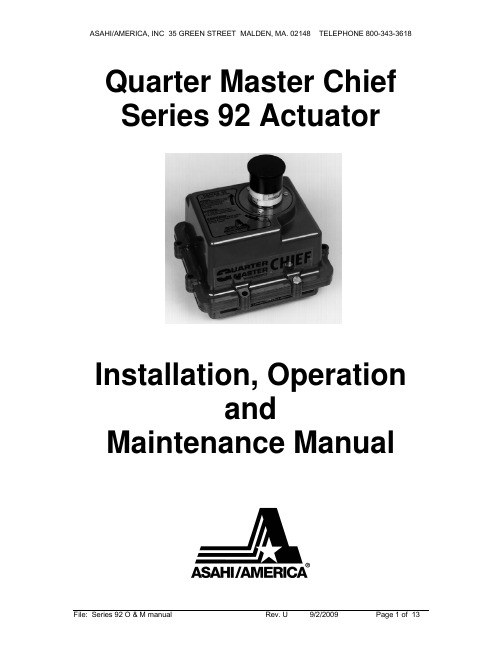
Quarter Master Chief Series 92 ActuatorInstallation, Operationand Maintenance ManualTable of ContentsSeries 92 Electric Actuator Introduction (3)Description (3)Electrical Requirement (3)Installation (4)Electrical (4)Type 21 Ball Valve (4)Type 23 Ball Valve (3-way) (5)Type 57 / 57L Butterfly Valves (5)Actuator Mounting Dimensions (6)Operation (7)Manual Override Operation (7)Setting Limit Switches (7)Options (8)Single Limit Switch (8)Double Limit Switch (8)Heater and Thermostat (8)Mechanical Brake (9)Feedback Potentiometer (9)Series 92 Options Codes for Serial # Tags (10)Troubleshooting (10)Maintenance (12)ATEX Requirements (12)Spare Parts (13)Series 92 Electric Actuator IntroductionDescriptionThe Series 92 electric actuators feature a reversing,capacitor run motor, with a permanently lubricated gear train, and hardened steel spur gears. These actuators are equipped with integral thermal overload protection (AC models) with automatic reset, independently adjustable limit switches, declutchable manual override, beacon position indication, baked powder epoxy coating with stainless steel trim, ISO bolt circle, and 2 (two) ½” NPT conduit entries.Standard models are offered in 115 VAC, feature a combination enclosure of Nema-4X, 7 & 9, and, provide up to 2000 in-lbs. of output torque.Various options are available such as operating voltages, additional limit switches, heater and thermostat, feedback potentiometers, etc.Please see page 8 regarding these options.Electrical RequirementWARNING: Do not open actuator cover while circuits are energized.CAUTION: Proper voltage must be supplied to actuator or damage will result.CAUTION: If 115vac & 220vac models are PLC driven, output contacts of PLC should be rated at a minimum of 1.5 times required input voltage of actuatorNOTE: To conform to various electrical codes, a green grounding screw has been provided (on the baseplate) inside of actuator.Terminal Strip Wiring: 75° C Copper Supply Wires up to #14 AWG, wired as per the attached diagrams or the wiring diagram affixed inside of actuator cover. Control Wiring shall be insulated with conductors rated 105° C, 300 V minimum.Torque Terminal Strip Wiring to 5 in-lbs.115 Vac 230 Vac 12 Vdc 24 Vdc 12 Vac 24 Vac Cycle Timeper 90 Model Torque Amp Duty Amp Duty Amp Duty Amp Duty Amp Duty Amp DutyDegrees (in/lbs) Draw Cycle Draw Cycle Draw Cycle Draw Cycle Draw Cycle Draw Cycle (seconds) S92 400 0.5 100% 0.4 100% 2.075% 4.075% 2.075% 3.0 75% 10A92 700 0.8 75% 0.6 75% 2.075% 4.075% 2.075% 3.0 75% 10B92 1100 0.5 100% 0.4 100% 2.075% 4.075% 2.075% 3.0 75% 25C92 2000 1.0 50% 0.6 50% 2.075% 4.075% 2.075% 3.0 75% 25 NOTE: Amp rating is considered locked rotor.Duty cycles are for ambient temperature (73°F)InstallationElectricalReference Drawing #289S92Models S-92, A92, & B921A. To gain access to terminal strip (Part #24) it is necessary to remove manual override knob (Part #18) by loosening slotted setscrew (Part #39). Remove 2 cover screws and cover; the remaining 6 cover screws are packaged inside the actuator. Torque cover/base screws to 120 in-lbs.Note: Failure to properly tighten cover/base flange fasteners to 120 in/lbs may compromise the certified safety factors of the actuator.Model C921B. To gain access to terminal strip it is necessary to remove manual override hand wheel (Part #18A) by loosening slotted setscrew (Part #39). Remove cam (Part #51) by loosening 2 set screws (Part #52). Remove 2 cover screws and cover; the remaining 6 cover screws are packaged inside the actuator.Torque cover/base screws to 120 in-lbs.All Models2. Make electrical connections to terminal strip as shown on wiring schematiclocated inside the cover (per various electrical codes there is a green screw on the actuator base plate for grounding purposes). Terminals are suitable for up to #14 AWG wire. All units are completely calibrated prior to shipment, and no internal adjustments should be required.3. For United States units, Install 1/2" NPT conduit fitting(s) to actuator base.For ATEX Certified European Union units, Install M20 x 1.5 conduit fitting(s) to actuator base.Note: Proper conduit fitting must be used to maintain enclosure rating and not compromise the certified safety factors of the actuator(weatherproof, explosion proof or combination weather proof/explosion proof). NOTE: We recommend sealing conduit openings on units installed outdoors or exposed to large temperature swings (15ºF or more).We also recommend the Heater and Thermostat option in these applications. 4. Replace actuator (gasket if removed) cover, and install 8 cap screws suppliedand tighten securely to 120 in/lbs. For outdoor or wet locations it isrecommended prior to replacing the cover that the top shaft seal be cleaned and coated with silicone grease. Also clean shaft and lightly coat seal area of shaft with silicone grease. Unit is now ready for operation.Type 21 Ball ValvePosition the valve and the actuator to corresponding positions (either OPEN or CLOSED). The flats on the actuator shaft extension indicate valve positionType 21 Ball Valves (See Drawing #0107BV sizes ½” – 2”)Install mounting bracket #3 to actuator #2 using bolts #8 and washers #9. Insert coupling #4 on stem of valve #1 and then bolt valve #1 to mounting bracket #3 using bolts #5, nuts #7, and washers #6.Note: All bolts should be snug and not excessively over tightened.Type 21 Ball Valves (See Drawing #0113BV sizes 2-1/2” - 4")Install mounting bracket #3 to actuator #2 using bolts #8 and washers #9. Insert coupling #4 on stem of valve #1 and then bolt valve #1 to mounting bracket #3 using bolts #5, nuts #7, and washers #6.Note: All bolts should be snug and not excessively over tightened.Type 23 Ball Valve (3-way)Position the valve and the actuator to corresponding positions (either OPEN or CLOSED). The flats on the actuator shaft extension indicate valve positionType 23 Ball Valves (3-way): (See Drawing #0130BV, sizes ½” - 4”)Install mounting bracket #3 to actuator #2 using bolts #8 and washers#9. Insert coupling #4 on stem of valve #1 and then bolt valve #1 tomounting bracket #3 using bolts #5, nuts #7, and washers #6.Type 57 / 57L Butterfly ValvesCAUTION: If valve is in line, system must be shut down and have no line pressure before removing throttle plate and retaining washer.Position the valve and the actuator to corresponding positions (either OPEN or CLOSED). The flats on the actuator shaft extension indicate valve position Butterfly Valves (See Drawing # 0200BF57 sizes 1-1/2” - 6”)No specially machined stem or valve body drilling required. Remove handle (remove handle cap and hex head bolt) to expose throttle plate screws. Remove throttle plate and retaining washer to expose existing bolt pattern.Mount bracket #3 to actuator #2 with bolts #8 and washers #9 and tighten evenly. Insert coupling #4 into actuator #2.Install valve #1 onto mounting bracket #3 and align stem of valve to engage with coupling. (Line scribed on top of stem indicates disc orientation). Install bolts #5, washers #6 and nuts #7 and tighten evenly. Flats on actuator shaft indicate valve position. (Disc Orientation)Butterfly Valves (See Drawing #0168BF57 8” size)No specially machined stem or valve body drilling required. Remove gear operator by removing 4 thru bolts in body of valve to gear operator and lift off. Mount bracket #2 to actuator #10 using bolts #7 and washers #8. Insert actuator shaft adapter #9 into actuator #10. Install valve #1 to mounting bracket #2 and align stem of valve to engage with coupling. (Line scribed on top of stem indicates disc orientation). Install bolts #3, washers #4 & #5 and nuts #6 and tighten evenly. Flats on actuator shaft indicate valve position. (Disc Orientation) CAUTION: If mounted unit is installed other than straight up, the actuator should be supported independently to prevent side loading and loosening up ofOperationManual Override OperationReference Drawing #289S92Models S-92, A92, & B92Pull up the declutching knob (Part #18) and apply a 5/8" open end wrench to exposed flats and rotate within labeled limits as indicated by arrows.To re-engage simply rotate actuator shaft in the opposite direction until declutching knob drops back down into position.Model C92Push down on hand wheel (Part #18A) and rotate within labeled limits.To re-engage simply rotate actuator hand wheel until it moves up and re-engages.CAUTION: The manual override should only be used when there is no power applied to actuator. When power is restored the actuator will automatically resume normal operation.Setting Limit SwitchesReference Drawing #289S92Open Travel Limit Switch (Top Switch Part #25):Using declutchable manual override, move the valve into a full open position. Then loosen set screws on top cam (Part #40) and rotate cam (CCW) into limit switch arm until a click is heard, this designates the switch circuit has opened and defines a full open position. Tighten 2 set screws (Part #40) on cam.Close Travel Limit Switch (Bottom Switch Part #25):Using declutchable manual override, move the valve to a full closed position, loosen set screws on bottom cam (Part #40) and rotate cam (CW) into limit switch arm until a click is heard, this designates the switch circuit has opened and defines a full closed position. Tighten 2 set screws (Part #40) on cam.Manually position valve to midstroke. Reapply power to actuator and drive to open or closed position. Actuator motor will run. The shaft will not turn until drivepins (Part #7) reseat in drive gear. This could take up to 25 seconds.OptionsModels S92, A92, B92, C92Single Limit SwitchInstall additional limit switch on posts on opposite side of standard limit switches using screws provided.Wiring for switch is as follows:Pink = Common to Terminal #6Purple = NC to Terminal #7Blue = NO to Terminal #8Cam must be set so that this switch is tripped just ahead of Closed limit switch. Wire tie loose wiring and check operation before installing cover.Double Limit SwitchInstallation and wiring is the same as for the single limit switch, with the additionof wiring of the second switch as follows:Brown = Common to Terminal #9Green = NC to Ternimal #10Orange = NO to Terminal #11Cam must be set so that this switch is tripped just ahead of Open limit switch. Wire tie loose wiring and check operation before installing cover.Heater and ThermostatModels S92 & A92Install Heater into threaded hole located between actuator base gasket andmotor module.Wiring is as follows:Heater lead = Terminal #12Thermostat lead = Terminal #13Wire tie loose wiring and check operation before installing cover.Models B92 & C92Install Heater into threaded hole located between actuator shaft and motor module.Wiring is as follows:Heater lead = Terminal #12Thermostat lead = Terminal #13Wire tie loose wiring and check operation before installing cover.Mechanical BrakeLoosen two (2) motor screws diagonally from each other and install bracket with tabs facing upward. Tighten screwsInstall hexagonal adapter over armature shaft and tighten set screws.NOTE: The adapter should be resting on the step of the armature shaft.Install brake assembly onto hexagonal adapter making sure that the brake assembly is sitting flush on the bracket. Tighten with supplied screws.Remove motor leads “A” & “B” from capacitor and install “piggy back connectors to capacitor, the re-install motor leads to their original locations.Connect brake leads to piggy back connectors on capacitor (orientation does not matter)Wire tie loose wiring and check operation before installing cover.Feedback PotentiometerUsing 4-40 x 3/8 hardware, install potentiometer and bracket on standoffs by limit switches, with potentiometer gear facing output shaft.Install drive gear face down over output shaft.Wiring for potentiometer as follows:#1 on potentiometer (black) #14 on terminal strip.#2 on potentiometer (white) #15 on terminal strip.#3 on potentiometer (red) #16 on terminal strip.Using multimeter set at 2k ohms, calibrate potentiometer with leads from meter connected to terminals #15 and #16. With actuator in closed position multimeter should read between 95 and 100 ohms.Rotate actuator 90 degrees (open position).Connect leads from multimeter to terminal #14 and #15; multimeter should read 95 to 100 ohms.If necessary adjust open limit switch cam so that multimeter will read 95-100 ohms.Series 92 Options Codes for Serial # TagsExample 1: S92HTP XWJHeater & thermostat and feedback potentiometer installed.Example 2: A92BRM1XWJMechanical brake and 1 extra limit switch installed.Troubleshooting WARNING: Do not open actuator cover while circuits are energized.Q: What if there is no output, but the motor runs?A: Manual override possibly engaged.When the manual override is engaged, the motor will run, but no output will be observed until the manual override re-engages with the output shaft.A: Valve stem broken. When the valve stem is broken, there will not be a change in fluid movement, making it seem as if the actuator has no output..Q: What if valve does not cycle?A: No power source to actuator. Check for power.A: Power source disconnected. Check for broken wire, loose connection or no connection as per appropriate wiring diagram.A: Low or wrong power source. Check for proper voltage.A: Mechanical Brake jammed or misaligned. Check alignment of brake assembly.This could occur during installation when someone would rest their hand on the Mechanical Brake to steady themselves. M1 1 extra limit switchM2 2 extra limit switches HT Heater & thermostat P Feedback potentiometer DP Dual feedback potentiometers C1 4-20 mA Positioner C3 4-20mA Output Transmitter BR Mechanical brake L2 2-Position Indicating Lights CO Center offCL Cycle length control 2W 2-wire control FS Failsafe Battery Pak A4 4-12mA Input Signal Positioner B12 Split Range Positioner ASI AS-I Bus Network CardQ: What if there is water and/or moisture inside of the unit?A: Conduit fitting installed improperly. Re-install correctly.A: Cover and/or base seal damaged. Replace damaged seal(s).A: Base gasket damaged or installed improperly. Check gasket and replace if necessary.A: Temperature swings of more than 15 degrees F. Install heater and thermostat to eliminate condensation.When these temperature swings occur, the unit will “sweat” on the inside causing internal corrosion unless the actuator is equipped with a heater and thermostat to keep a constant temperature inside of the housing.A: Unit has been submerged. Raise unit above liquid level.An actuator that is to be submerged MUST meet NEMA 6 for the proper protection of the actuator and the elimination of a potential hazard. We do not recommend submerging the Series 92 Actuator as the electrical rating does not meet NEMA 6.Q: What if unit is oscillating?A: Valve torque exceeds output torque of actuator. Check for chemical compatibility of valve, and flange torque.Q: What if thermal overload frequently cuts out motor?A: Frequency of operation exceeds duty cycle rating. Check cycling period.A: Unit is oscillating. Refer to above.Q: What if motor hums and no output is observed?A: Foreign material caught in valve. Remove material and inspect valve for damaged and/or worn parts. Replace parts as necessary.A: Unit wired incorrectly (simultaneously powering open and closed). Check wiring as per appropriate wiring diagram.A: Capacitor worn. Replace.Q: What if actuator “over-shoots” limit switches without stopping?A: Actuator wired in parallel to each other. Please note that each actuator requires it’s own set of switch contacts.MaintenanceDisconnect power!WARNING: Do not open actuator cover while circuits are energized. ArrayCAUTION: It is imperative for reducing the chance of electrical shock, and to prevent ignition of hazardous atmospheres that youDisconnect powerbefore any maintenance or repairs are performed.Series 92 actuators are virtually maintenance free. We do however, recommend that periodic checks are made to ensure that all fasteners are tight and properly torqued to extend the life of the actuator and valve.Series 92 Actuators are manufactured with factory lubricated grease in the gear case and gearbox. In most cases, this lubricant should never have to be replenished, however if deemed necessary, we recommend using Aeroshell Grease #33 MS, mfg. by Shell Oil Co.Consult our technical department before replenishing lubricant.For outdoor or wet locations keep top and bottom seals coated with a silicone based grease.ATEX RequirementsATEX Standard EEx d IIB Directive II 2 G Certified UnitsService/Maintenance/Inspection RequirementsAbove directive for hazardous location service electric actuators, for use throughout the European Union.All electric actuators are to be used for remote operation of a valve to open or closed positions. Any other uses are not approved by Asahi/America, Inc.Every 250,000 cycles or 10 years whichever comes first, the actuator must be removed from service and sent back to Asahi/America, Inc. for inspection of wear of bearings as they relate to joints and gaps in accordance with above directive. Any units not within normal tolerances, will need to be re-built or replaced at theusers expense.Spare PartsReference Drawing #289S92We recommend that the following be kept on hand as spare parts.1 --- Limit Switch (Part #25)1 --- Capacitor (Part #27 or #28)NOTE: When ordering replacement motor parts and/or options specify model # and voltage.Attachments:9 drawings: 0043EL, 0044EL, 0042EL, 0107BV, 0113BV,0130BV, 0168BF57, 0200BF57, 289S92。
海斯特柴达菲尔产品技术指南说明书
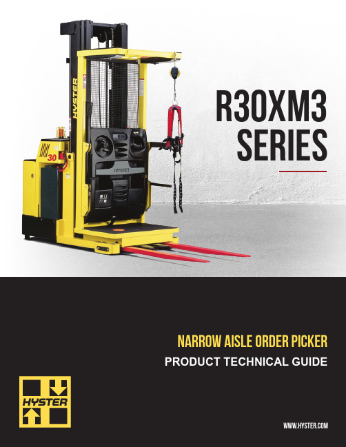
R30XM3 SERIESPRODUCT BROCHURE2*Turning radius is the same with or without guide rollers† Rated load figures are based on 3000 lb (1361 kg) load and a 24” load center.NOTE: Performance specifications are for truck with standard equipment. Performance specifications are affected by the condition of the vehicle and how it is equipped as well as the nature and condition of the operating area. If these specifications are critical, the proposed application should be discussed with your dealer.Lift heights over 360” (9144 mm) maximum fork height may require reduced capacity depending upon OEC dimensions.3Right angle stack and equal intersecting aisle dimensions provided with a 40” wide x 48” long pallet load, allowing zero clearance.1Speeds are the same in either direction, with or without rated load. Steer angle <10 degrees.2Optional with Hyster Power Cellect ™CERTIFICATION: These Hyster ® lift trucks meet the design and construction requirements of B56.1-1969, per OSHA Section 1910.178(a)(2), and also comply with the B56.1 revision in effect at time of manufacture. Performance specifications are for a truck equipped as described under standard equipment on this technical guide. Performance specifications are affected by the condition of the vehicle and how it is equipped, as well as by the nature, condition of the operating area, proper service and maintenance of the vehicle. If these specifications are critical, the proposedapplication should be discussed with your dealer.Battery compartment length is measured from front to rear. Battery compartment width is measured across truck. SB350 Amp “red” connector, cable position B, cable length 16” (405mm). Maximum cable gauge 1/0 AWG. Battery with lid will NOT fit in battery compartment. Battery weight range 1600 - 1900 lb.Amp hour capacity min/max - 24 volt truck 960/1240. 36 volt truck 600/775.Note: Speed limits are for trucks at operating temperature with fully charged battery. Speeds are the same in either direction, with or without rated load.For lift heights between 24.0” (610 mm) and 212.0” (5385 mm), traction speed is reduced when steering angle exceeds 10°.* T ravel above 212.0” (5385 mm) fork height requires a high level traction option. Capacity reduction required.Contact your local dealer for additional information.。
Festo电磁柄EPCS-BS-32商品说明书
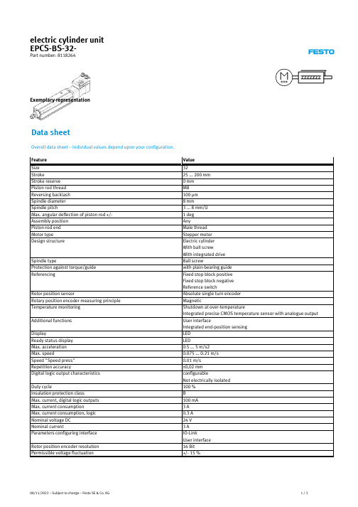
Duty cycle Insulation protection class Max. current, digital logic outputs Max. current consumption Max. current consumption, logic Nominal voltage DC Nominal current Parameters configuring interface
08/11/2023 – Subject to change – Festo SE & Co. KG
3/3
2/3
Feature
IO-Link, minimum cycle time IO-Link, data memory required Max. line length
Switching logic, outputs
Input circuit logic
Logic interface, connection type Logic interface, connection technology Logic interface, number of poles/wires Logic interface, connection pattern Mounting type
IO-Link, process data width IN IO-Link, process data content IN
Festo MFH-3-3 4-S-EX 手动覆盖螺纹阀门说明书
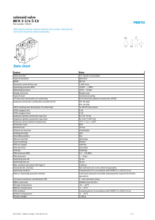
Value
Via F coil, must be ordered separately with through hole M5 M5 G1/8 G3/4 G3/4 G3/4 Conforms to RoHS NBR Aluminium die cast
08/11/2023 – Subject to change – Festo SE & Co. KG
UKCA marking (see declaration of conformity) ATEX category Gas ATEX category Dust Explosion ignition protection type Gas Explosion ignition protection type Dust Explosion-proof ambient temperature Protection class Nominal size Exhaust-air function Sealing principle Assembly position Manual override Type of piloting Pilot air supply Flow direction Overlap Pilot pressure MPa Pilot pressure Switching time off Switching time on Max. positive test pulse with logic 0 Characteristic coil data Operating medium Note on operating and pilot Valve function Type of actuation Width Standard nominal flow rate Operating pressure MPa Operating pressure Design structure Type of reset CE mark (see declaration of conformity) Explosion protection certification outside the EU
布拉斯盖子二路指引型自主闭合型紧凑型电磁阀-SBSV-B系列电磁阀说明书
Brass
Solenoid
Valves
-
2-Way
Guided
NC
Compact Design, Immune to Mounting Orientation
Valves, Solenoid
B
C
D A
Scan here to watch product video
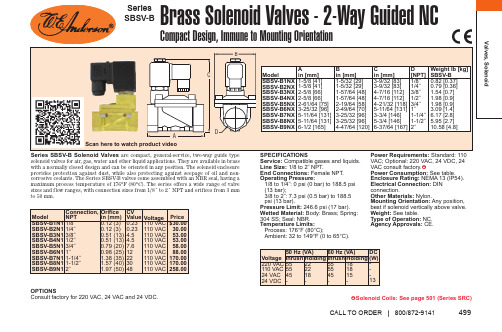
Series SBSV-B Solenoid Valves are compact, general-service, two-way guide type solenoid valves for air, gas, water and other liquid applications. They are available in brass with a normally closed design and can be oriented in any position. The solenoid enclosure provides protection against dust, while also protecting against seepage of oil and noncorrosive coolants. The Series SBSV-B valves come assembled with an NBR seal, having a maximum process temperature of 176°F (80°C). The series offers a wide range of valve sizes and flow ranges, with connection sizes from 1/8˝ to 2˝ NPT and orifices from 3 mm to 50 mm.
辰竹 浪涌保护安全栅 LBGS8023-EX 使用说明书

使用说明书辰竹官方微信地址:上海市民益路201号漕河泾开发区松江新兴产业园6号楼邮编:201612 总机:021-******** 传真:021-********销售服务:021-******** 技术支持:400 881 0780邮箱:chenzhu @chenzhu -inst .com LBGS8023-EX(防爆合格证号:GYB17.1474)浪涌保护安全栅CZ.LBGS8023-EX.11(S)-5.1/17.03接线安装拆卸⑴ 用螺丝刀(刀口宽度≤6mm)插入仪表下端的金属卡锁; ⑵ 螺丝刀向上推,把金属卡锁向下撬; ⑶ 仪表向上拉出导轨。
维护⑴ 浪涌保护安全栅进行通电调试前,必须再次检查浪涌保护安全栅的型号及防爆等级是否与设计和使用环境相符,必须再次检查安全侧与危险侧的接线以及它们电源和信号的极性是否正确;⑵ 严禁用兆欧表测试浪涌保护安全栅端子之间的绝缘性。
若要检查系统线路绝缘性时,应先断开全部浪涌保护安全栅接线,否则会引起内部快速熔断器熔断;⑶ 产品在出厂前均经过严格检验和质量控制,如发现工作不正常,怀疑内部模块有故障,请及时同最近的代理商或直接与技术支持热线联系;⑷ 产品从发货之日起五年以内,正常使用过程中出现产品质量问题均由辰竹免费维修。
54使用产品前请仔细阅读本使用说明书,并请妥善保管⑴ 仪表接线采用可拆卸的接线端子,方便使用。
本安端(蓝色插头)为通向危险侧的信号接线端,非本安端(绿色插头)为通向安全侧的信号接线端;⑵ 本安侧的配线应选用有蓝色标记的本安导线,导线的软2铜截面积必须大于1.5mm 绝缘强度应大于500V;⑶ 浪涌保护安全栅本安端和非本安端的配线导线在汇线槽中应分开铺设、各自采用保护套管;⑷ 导线裸露长度约为8mm 由M3螺钉锁紧。
,,本安端非本安端浪涌保护安全栅应安装在安全场所,LBGS8000-EX系列浪涌保护安全栅均采用DIN35mm导轨安装方式。
安装步骤如下:⑴ 把仪表上端卡在导轨上; ⑵ 把仪表下端推进导轨。
赛尔开关操作规程
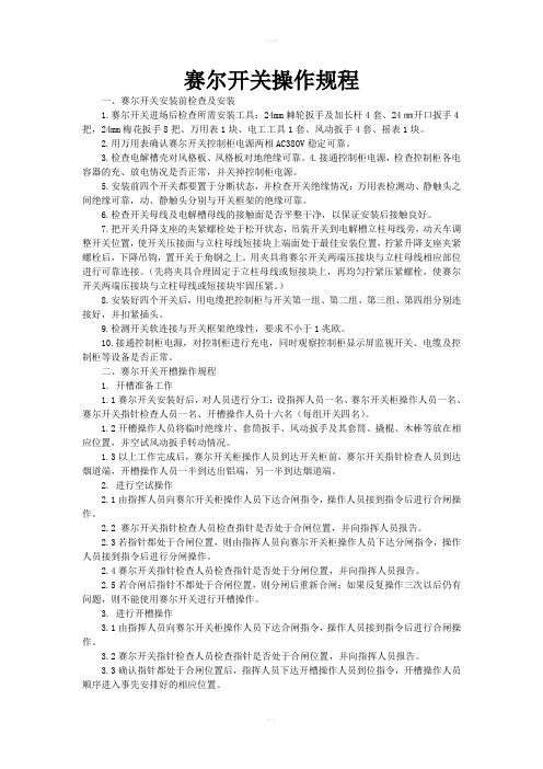
赛尔开关操作规程一、赛尔开关安装前检查及安装1.赛尔开关进场后检查所需安装工具:24mm棘轮扳手及加长杆4套、24㎜开口扳手4把,24mm梅花扳手8把、万用表1块、电工工具1套、风动扳手4套、摇表1块。
2.用万用表确认赛尔开关控制柜电源两相AC380V稳定可靠。
3.检查电解槽壳对风格板、风格板对地绝缘可靠。
4.接通控制柜电源,检查控制柜各电容器的充、放电情况是否正常,并关掉控制柜电源。
5.安装前四个开关都要置于分断状态,并检查开关绝缘情况:万用表检测动、静触头之间绝缘可靠,动、静触头分别与开关框架的绝缘可靠。
6.检查开关母线及电解槽母线的接触面是否平整干净,以保证安装后接触良好。
7.把开关升降支座的夹紧螺栓处于松开状态,吊装开关到电解槽立柱母线旁,动天车调整开关位置,使开关压接面与立柱母线短接块上端面处于最佳安装位置,拧紧升降支座夹紧螺栓后,下降吊钩,置开关于角钢之上。
用夹具将赛尔开关两端压接块与立柱母线相应部位进行可靠连接。
(先将夹具合理固定于立柱母线或短接块上,再均匀拧紧压紧螺栓,使赛尔开关两端压接块与立柱母线或短接块牢固压紧。
)8.安装好四个开关后,用电缆把控制柜与开关第一组、第二组、第三组、第四组分别连接好,并扣紧插头。
9.检测开关软连接与开关框架绝缘性,要求不小于1兆欧。
10.接通控制柜电源,对控制柜进行充电,同时观察控制柜显示屏监视开关、电缆及控制柜等设备是否正常。
二、赛尔开关开槽操作规程1. 开槽准备工作1.1赛尔开关安装好后,对人员进行分工:设指挥人员一名、赛尔开关柜操作人员一名、赛尔开关指针检查人员一名、开槽操作人员十六名(每组开关四名)。
1.2开槽操作人员将临时绝缘片、套筒扳手、风动扳手及其套筒、撬棍、木棒等放在相应位置,并空试风动扳手转动情况。
1.3以上工作完成后,赛尔开关柜操作人员到达开关柜前,赛尔开关指针检查人员到达烟道端,开槽操作人员一半到达出铝端,另一半到达烟道端。
- 1、下载文档前请自行甄别文档内容的完整性,平台不提供额外的编辑、内容补充、找答案等附加服务。
- 2、"仅部分预览"的文档,不可在线预览部分如存在完整性等问题,可反馈申请退款(可完整预览的文档不适用该条件!)。
- 3、如文档侵犯您的权益,请联系客服反馈,我们会尽快为您处理(人工客服工作时间:9:00-18:30)。
注意:提醒需要特别注意的信息。
ATTENTION: Identifies information that requires special consideration.
提示:标记对用户的建议或提示。 TIP:Identifies advice or hints for the user.
目
录
隔离式安全栅 SB3042-Ex.............................................................................................................................. 1 1 基本说明..................................................................................................................................................... 1 2 性能指标..................................................................................................................................................... 1 3 使用说明..................................................................................................................................................... 2 4 资料版本说明............................................................................................................................................. 2
电击危险:标示有可能产生电击危险的信息。
Risk of electrical shock: Indicates information that Potential shock hazard where HAZARDOUS LIVE voltages greater than 30V RMS, 42.4V peak, or 60V DC may be accessible.
安全参数
适用的现场设备
1
SB3042-Ex 使用手册
3 使用说明
图 3-1 SB3042-Ex 接线图 表 3-1 SB3042-Ex 接线方法 端子符号 1 4 5 2 3 7 10 8 11 9 12 连接方法 变送器供电+端 手操器+端 手操器-端 电流输入端 现场侧公共端 手操器+端 手操器-端 (4~20)mA 电流输出+端 (4~20)mA 电流输出-端 电源供电+端 电源供电-端
SB3042-Ex 使用手册
42 -Ex 隔离式安全栅 SB30 SB3042 42-Ex
1 基本说明
SB3042-Ex 电流输入型智能隔离式安全栅为现场 2/3 线制变送器提供一组隔离的供电电源, 并将 现场的(4~20)mA 电流信号隔离复制到输出端。对于 2 线制变送器,SB3042-Ex 支持双向 HART 协议通讯。
警告:标示有可能导致人身伤亡或设备损坏的信息。
WARNING: Indicates information that a potentially hazardous situation which, if not avoided, could result in serious injury or death.
隔离式安全栅
42 -Ex 使用手册 SB30 SB3042 42-Ex
浙江中控技术股份有限公司
声
� �
�
明
严禁转载本手册的部分或全部内容。 在不经预告和联系的情况下,本手册内容有可能发生变更,请谅解。 本手册所记载的内容,不排除有误记或遗漏的可能性。如对本手册内容有疑问,
请与我公司联系。
文档标志符定义
2 性能指标
表 2-1 性能指标 型号 通道数 现场设备防爆等级 配电输出电源 输出信号范围 信号输出特性 转换精度 温度漂移 数字信号带宽 供电电源 隔离电压 SB3042-Ex 1 现场的设备经过适当认证后,可使用于 0 区、ⅡC、T4-T6 的危险场所 输出电流 20mA 时,配电电压大于 16.5V DC *注:配电回路开路时,最大配电电压为 28V DC (4~20)mA 负载能力: (0~650)Ω 输出纹波:峰峰值小于 40μA 响应时间:20ms 以内达到最终值的 90% 优于±16μA 优于±1μA/℃ 10Hz~12kHz 电压: (20~35)V DC 电流:24V 时,80mA;20V 时,90mA;35V 时,60mA 功率:1.92W(24V 供电,20mA 输出时) 安全侧和危险侧隔离电压 250V AC/DC 国家仪器仪表防爆安全监督检验站 NEPSI 认证参数(防爆合格证号: GYB081298) 端子 1-3-2、端子 1-2 以及端子 4-5: Uo=28V,Io=93mA,Co=0.083μF,Lo=4.2mH,Po=0.66W 端子 2-3: Uo=5V,Co=100μF 智能变送器: SupField™CXT 系列、CJT 系列智能变送器 Honeywell-ST3000 系列智能变送器 E+H-Deltabar 智能压力变送器 横河 EJA 智能变送器 Rosemount-3051 系列智能变送器 各类通用 2/3 线制变送器: SupField™ SP00 系列压力变送器 金属转子流量计
4 资料版本说明
表 4-1 版本升级更改一览表 资料版本号 SB3042-Ex 使用手册(V1.0) 适用产品型号 SB3042-Ex 更改说明
2
防止静电:标示防止静电损坏设备的信息。
ESD HAZARD: Indicates information that Danger of an electro-static discharge to which equipment may be sensitive. Observe precautions for handling electrostatic sensitive devices
