Q62702-F1062中文资料
Q62702-P936中文资料

Silizium-PIN-Fotodiode mit sehr kurzer SchaltzeitSilicon PIN Photodiode with Very Short Switching TimeWesentliche Merkmaleq Speziell geeignet für Anwendungen im Bereich von 350 nm bis 1100 nm q Kurze Schaltzeit (typ. 5 ns)q Hermetisch dichte Metallbauform (TO-18)Anwendungenq Schneller optischer Empfänger mit gro βer Modulationsbandbreite für LichtgriffelFeaturesq Especially suitable for applications from 350 nm to 1100 nmq Short switching time (typ. 5 ns)q Hermetically sealed metal package (TO-18)Applicationsq Optical sensor of high modulation bandwidth for light pensTyp Type Bestellnummer Ordering Code SFH 216Q62702-P936SFH 216Maße in mm, wenn nicht anders angegeben/Dimensions in mm, unless otherwise specified.f e o 06314GrenzwerteMaximum Ratings Bezeichnung DescriptionSymbol SymbolWert Value Einheit Unit Betriebs- und LagertemperaturOperating and storage temperature range T op ;T stg – 40...+ 125°C Löttemperatur (Lötstelle 2 mm vom Gehäuse entfernt bei Lötzeit t ≤ 3 s)Soldering temperature in 2 mm distance from case bottom (t ≤ 3 s)T S230°CSperrspannung Reverse voltageV R 50V Verlustleistung,T A = 25°C Total power dissipationP tot250mWKennwerte (T A = 25°C, Normlicht A,T = 2856 K)Characteristics (T A = 25°C, standard light A,T = 2856 K)Bezeichnung DescriptionSymbol SymbolWert Value Einheit Unit Fotoempfindlichkeit,V R = 5 V Spectral sensitivityS50 (≥35)nA/Ix Wellenlänge der max. Fotoempfindlichkeit Wavelength of max. sensitivityλS max 850nm Spektraler Bereich der Fotoempfindlichkeit S = 10 % von S maxSpectral range of sensitivity S = 10 % of S maxλ350 (1150)nmBestrahlungsempfindliche Fläche Radiant sensitive areaA 1mm 2Abmessung der bestrahlungsempfindlichen FlächeDimensions of radiant sensitive area L ×B L ×W 1×1mmAbstand Chipoberfläche zu Gehäuseober-flächeDistance chip front to case surface H4.2...5.0mmHalbwinkel Half angleϕ±12Grad deg.Dunkelstrom,V R = 20 V Dark currentI R1 (≤ 5)nASpektrale Fotoempfindlichkeit,λ = 850 nmSpectral sensitivitySλ0.55A/WQuantenausbeute,λ = 850 nm Quantum yield η0.80ElectronsPhotonLeerlaufspannung,E v = 1000 Ix Open-circuit voltage VO410 (≥350)mVKurzschlußstrom,E v = 1000 Ix Short-circuit current ISC50µAAnstiegs und Abfallzeit des Fotostromes Rise and fall time of the photocurrentRL = 50Ω;V R= 20 V;λ = 850 nm;I p = 800µAtr,t f5nsDurchlaßspannung,I F= 100 mA,E = 0 Forward voltage VF1.3VKapazität,V R= 0 V,f= 1 MHz,E = 0 Capacitance C11pFTemperaturkoeffizient von V O Temperature coefficient of V O TCV– 2.6mV/KTemperaturkoeffizient von I SC Temperature coefficient of I SC TCI0.2%/KRauschäquivalente Strahlungsleistung Noise equivalent powerVR = 20 V,λ = 850 nmNEP 3.3×10⁻¹⁴ W√HzNachweisgrenze,V R= 20 V,λ = 850 nm Detection limit D* 3.1×1012cm ·√HzWKennwerte(T A = 25°C, Normlicht A,T = 2856 K) Characteristics(T A = 25°C, standard light A,T = 2856 K)Bezeichnung Description SymbolSymbolWertValueEinheitUnitRelative spectral sensitivity S rel =f (λ)Dark current I R =f (V R ),E= 0Photocurrent I P =f (E v ),V R = 5 V Open-circuit-voltage V O =f (E v )CapacitanceC =f (V R ),f = 1 MHz,E= 0Total power dissipation P tot =f (T A )Dark currentI R =f (T A ),V R = 1 V,E= 0Directional characteristics S rel =f (ϕ)。
Q62702-A693中文资料

Silicon Switching Diode Array
q q
BAV 74
For high-speed switching Common cathode
Type BAV 74
Marking JAs
Ordering Code (tape and reel) Q62702-A693
Semiconductor Group
2
元器件交易网
BAV 74
Forward current IF = f (TA*; TS) * Package mounted on epoxy
Reverse current IR = f (TA)
Forward current IF = f (VF) TA = 25 ˚C
Pin Configuration
Package1) Sper Diode Parameter Reverse voltage Peak reverse voltage Forward current Surge forward current, t = 1 µs Total power dissipation, TS = 35 ˚C Junction temperature Storage temperature range Thermal Resistance Junction - ambient2) Junction - soldering point Rth JA Rth JS
µA
Values typ. max.
Unit
V
Test circuit for reverse recovery time
Pulse generator: tp = 100 ns, D = 0.05 tr = 0.6 ns, Rj = 50 Ω
Q62702-G44资料
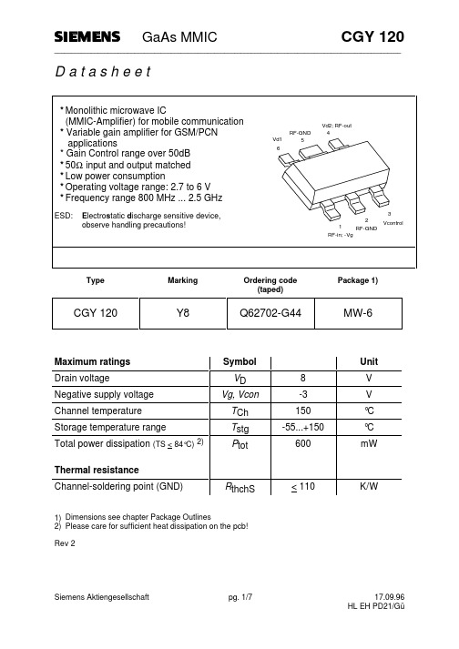
Siemens Aktiengesellschaft
pg. 1/7
17.09.96 HL EH PD21/Gü
元器件交易网
GaAs MMIC
Electrical characteristics TA = 25°C f = 900 MHz Characteristics Power Gain Vd=3V; I=45mA; Vcon=2V Vd=5V; I=70mA; Vcon=2V Input return loss Vd=3V; I=45mA; Vcon=2V Vd=5V; I=70mA; Vcon=2V Output return loss Vd=3V; I=45mA; Vcon=2V Vd=5V; I=70mA; Vcon=2V Gain Control Range
C1 , C2 Siemens B37490-K5120-J62 R1 Siemens B54102-A1471-J60 L1 Coilcraft 0805CS-270XMBC C4 Siemens B37940-K5220-J62 R2 Siemens B53102-A1511-J60 L2 Coilcraft 0805CS-220XMBC C3 , C5 Siemens B37940-K5681-J62 For optimized device performance, Vg has to be adapted (Vg ≈ -1V...0V) to I ≈ 45mA at Vd-supply under condition Vcontrol=+2V.
dG P1dB
1dBm gain compression Vd=3V; I=45mA; Vcon=2V Vd=5V; I=70mA; Vcon=2V
SFH214中文资料

Neu:Silizium-PIN-Fotodiode mit sehr kurzer Schaltzeit New:Silicon PIN Photodiode with Very ShortSwitching TimeTyp Type Bestellnummer Ordering CodeSFH 214Q62702-P922SFH 214 FAQ62702-P1672SFH 214SFH 214 FAMaße in mm, wenn nicht anders angegeben/Dimensions in mm, unless otherwise specified.f e o f 6652f e o 06652Wesentliche Merkmaleq Speziell geeignet für Anwendungen im Bereich von 400 nm bis 1100 nm(SFH 214) und bei 880 nm (SFH 214 FA)q Kurze Schaltzeit (typ. 5 ns)q 5 mm-Plastikbauform im LED-Gehäuse q Auch gegurtet lieferbarAnwendungenq Industrieelektronikq “Messen/Steuern/Regeln”q Schnelle Lichtschranken für Gleich- und Wechsellichtbetrieb q LWL Featuresq Especially suitable for applications from 400 nm to 1100 nm (SFH 214) and of 880 nm (SFH 214 FA)q Short switching time (typ. 5 ns)q 5 mm LED plastic package q Also available on tapeApplicationsq Industrial electronicsq For control and drive circuits q Photointerruptersq Fiber optic transmission systemsGrenzwerteMaximum Ratings Bezeichnung DescriptionSymbol SymbolWert Value Einheit Unit Betriebs- und LagertemperaturOperating and storage temperature range T op ;T stg – 55...+ 100°C Löttemperatur (Lötstelle 2 mm vom Gehäuse entfernt bei Lötzeit t ≤ 3 s)Soldering temperature in 2 mm distance from case bottom (t ≤ 3 s)T S300°CSperrspannung Reverse voltage V R 50V VerlustleistungTotal power dissipationP tot100mWKennwerte (T A = 25°C)Characteristics Bezeichnung DescriptionSymbol SymbolWert ValueEinheit UnitSFH 214SFH 214 FAFotoempfindlichkeit Spectral sensitivityV R = 5 V, Normlicht/standard light A,T = 2856 K,V R = 5 V,λ = 870 nm,E e = 1 mW/cm 2S S45 (≥ 30)––25 (≥ 20)nA/Ix µA Wellenlänge der max. Fotoempfindlichkeit Wavelength of max. sensitivityλS max 850900nm Spektraler Bereich der Fotoempfindlichkeit S = 10 % von S maxSpectral range of sensitivity S = 10 % of S maxλ400...1100750 (1100)nmBestrahlungsempfindliche Fläche Radiant sensitive areaA 11mm 2Abmessung der bestrahlungsempfindlichen FlächeDimensions of radiant sensitive area L ×B L ×W 1×11×1mm ×mmAbstand Chipoberfläche zu Gehäuseober-flächeDistance chip front to case surfaceH3.4...4.0 3.4...4.0mmHalbwinkel Half angleϕ±40±40Grad deg.Dunkelstrom,V R = 20 V Dark currentI R 1 (≤ 5) 1 (≤ 5)nA Spektrale Fotoempfindlichkeit,λ = 850 nm Spectral sensitivityS λ0.620.59A/W Quantenausbeute,λ = 850 nm Quantum yieldη0.890.86Electrons Photon Leerlaufspannung Open-circuit voltageE v = 1000 Ix, Normlicht/standard light A,T = 2856 KE e = 0.5 mW/cm 2,λ = 870 nmV O V O380 (≥ 300)––340 (≥ 290)mV mVKurzschlußstrom Short-circuit currentE v = 1000 Ix, Normlicht/standard light A,T = 2856 KE e = 0.5 mW/cm 2,λ = 870 nmI SC I SC 42––12µA µA Anstiegs- und Abfallzeit des Fotostromes Rise and fall time of the photocurrentR L = 50Ω;V R = 20 V;λ = 850 nm;I p = 800µA t r ,t f55nsDurchlaßspannung,I F = 80 mA,E = 0Forward voltageV F 1.3 1.3V Kapazität,V R = 0 V,f = 1 MHz,E = 0CapacitanceC 01111pF Temperaturkoeffizient von V O Temperature coefficient of V O TC V – 2.6– 2.6mV/K Temperaturkoeffizient von I SC Temperature coefficient of I SC Normlicht/standard light A λ = 870 nmTC I0.18––0.2%/KRauschäquivalente Strahlungsleistung Noise equivalent power V R = 10 V,λ = 850 nmNEP2.9×10– 14 2.9×10– 14W √Hz Nachweisgrenze,V R = 20 V,λ = 850 nm Detection limitD*3.5×10¹² 3.5×1012cm ·√Hz WKennwerte (T A = 25°C)Characteristics (cont’d)Bezeichnung Description Symbol SymbolWert ValueEinheit UnitSFH 214SFH 214 FARelative spectral sensitivity SFH 214S rel =f (λ)Photocurrent I P =f (E e ),V R = 5 V Open-circuit voltage V O =f (E e )SFH 214 FARelative spectral sensitivity SFH 214 FA S rel =f (λ)Total power dissipation P tot =f (T A)Photocurrent I P =f (E v ),V R = 5 V Open-circuit voltage V O =f (E v )SFH 214Dark current I R =f (V R ),E= 0Directional characteristics S rel =f (ϕ)。
电气材料介绍
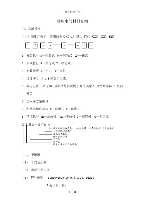
常用电气材料介绍一、高压系统:(一)高压开关柜:常用的型号GG-1A (F )、JYN 、HXGN 、XGN 、KYN1 分类代号 K —铠装式 J---间隔式 X---箱式2 形式特征 G —固定式 Y —移动式3 安装场所 N —户内 W —室外4 设计序号 由1-3位数字组成5 额定电压 单位KV 后面括号内说明主开关类型Z-真空断路器 F-负荷开关6 主回路方案编号7 断路器操作机构 D —电磁式 T —弹簧式8 环境代号 TH —是热带 TA —干热带 G —高海拔 Q —全工况(二)变压器 (1) 干式变压器 (2) 油浸式变压器(3) 符号说明: SCB10-1600/10,0.4/0.23, DYN11S 是代表三相;C代表环氧树脂浇注绝缘;B 配电变压器;10 设计序号1600/10 是容量1600KVA,高压侧电压10KV ;0.4/0.23 低压侧额定线电压、额定相电压;Dyn11 接线方式表示的是一次侧三相三角形接线,低压侧星形接线,低压侧线电压为11点,即:低压侧线电压超前高压侧线电压30度二、低压开关柜:常用的型号GGD、 GCK、GCS、MNS、MCS1—分类代号 P----开启式低压开关柜 G—封闭式低压开关柜;2—形式特征 G—固定式 C—抽出式 H—固定和抽出混合安装3—用途代号 L或D—动力用 K—控制用4—设计序号5—主电路方案编号6—辅助电路方案编号MNS是采用ABB系列注册商标之一,是ABB专用低压抽屉式开关柜MCS 是智能型低压开关柜1.电容补偿柜:以补偿容量Kvar来确认大小2.非标动力箱(1)落地式常用XL-21(2)壁挂式(明装、暗装)常用XL-063.照明配电箱1结构特征代号 P----开启式 G—封闭柜式;X—封闭箱式 BX—防爆箱式2形式特征 G—固定式 C—抽出式 Z—组合式3用途代号 L或D—动力用 K—控制用 M---照明4设计序号5安装方式暗装用R\明装不标注6设计序号7输出回路数8主开关代号PZ-30系列(室内)(1)明装型(2)暗装型PZ(R)-30XM-02系列(户外)(1)明装型(2)暗装型XM(R)-02防爆型BXM(D)52系列回路数一般为2的倍数和54.插座箱:普通型、防水、防尘型、防爆型型号含义KYN28A-12中置式开关柜KYN1-12装移开关柜XGN15-12交流环网开关柜GCS-低压抽出式开关柜GCK GCL-低压抽出式开关柜MNSG-低压抽出式开关柜GGD-低压固定式开关柜YB-系列预装式变电站XL21-动力配电箱PZ30-照明配电箱三、母线1.按结构分,母线型号及意义QLFM型全连式离相封闭母线FQFM型分段全连式离相封闭母线GXFM型共箱母线GGFM型共箱隔相母线CCX6密集绝缘插接式母线槽CCX-6-2000-A-3000-5GFM-高压共箱封闭母线槽CFW-高强封闭母线槽CCX-密集型封闭母线槽KFM-空气式母线槽LMC-铝壳母线槽NHMC-耐火型母线槽ZMC-照明母线槽2. 母线槽按材质分:铜母线、铝母线、铜铝复合型,按回路:3线制、4线制、5线3.附件:始端箱、连接器、连接器壳、膨胀节、弯头、分支接头、终端盖、固定卡子、插接箱4.安装订货要求:(1)插接口位置选择:上插、左插、右插,双侧插,(2)插接口数量要求:每1米或是3米一个,根据实际需要;(3)由于母线无法现场制作,对于弯头、变径、分支接头等必须由母线厂家在现场实际测量尺寸后定制,通常母线厂家会根据施工图和现场测量数据提供母线连接图,会给每一趟的每一节进行编号,安装时可根据编号顺序进行;四、桥架、线槽XQJ---形式---类别---规格XQJ ----汇线桥架系列 (BHQ—玻璃钢桥架系列)形式-----T梯级式、P盘式、C槽式、ZH组合式类别----类别种类(用阿拉伯数字加英文字母表示)规格---规格或是规格序号(用阿拉伯数字表示)宽*高*重大跨距XQJ—DJ--T—01A—300*1001.按规格分为:梯式(焊接成型)、盘式(一次冲压成型或是焊接成型)、槽式(一次冲压成型);2.按材质分:钢制、铝合金、不锈钢、复合材料(环氧树脂、玻璃钢、PVC)3.按结构分:普通型、加强型、大跨距(通常是加强型)、带分隔板(动力/控制)4.按表面处理:热镀锌、喷塑、防火5.按用途:6.长度:通常为2、4、6米/节,可根据实际要求定制7.附件:成品支架(根据安装位置的不同分为很多构配件),盖板、盖板锁扣、弯头(水平、垂直上弯、垂直下弯、左上、左下弯通、右上、右下弯头),三通、四通(等径、变径、水平、垂直),连接片、专用连接螺栓、调高片、调宽片、端盖、跨接铜辫子等8.订货时可要求供货商提供产品样本,根据产品样本内的规格型号选择进行订货9.钢制梯式和盘式的钢板厚度要求桥架宽度=b 钢板最小厚度要求B 100 1100 B 150 1.2150 B 400 1.5400 B 800 2800 B 2.510.镀锌层厚度:桥架构件不小于65μm; 螺栓及杆件不小于54μm11.镀锌层附着力测试:划线、划格、镀锌层不剥离、不凸起12.外观检查:表面光滑均匀、致密、不起皮、花斑、局部未镀、划痕等缺陷五、电缆(一)电线电缆产品主要分为五大类:1、裸电线及裸导体制品本类产品的主要特征是:纯的导体金属,无绝缘及护套层,如钢芯铝绞线、铜铝汇流排、电力机车线等;加工工艺主要是压力加工,如熔炼、压延、拉制、绞合/紧压绞合等;产品主要用在城郊、农村、用户主线、开关柜等。
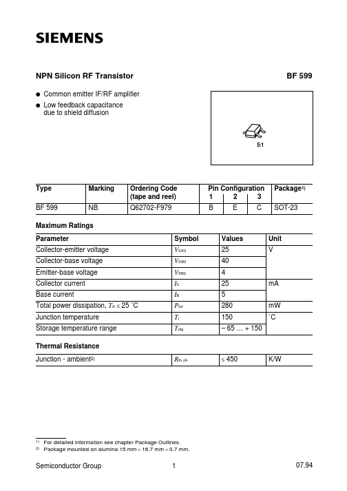
BF599中文资料
Semiconductor Group
2
BF 599
Total power dissipation Ptot = f (TA)
DC current gain hFE = f (IC) VCE = 10 V
Collector current IC = f (VBE) VCE = 10 V
Collector-emitter saturation voltage IC = f (VCEsat) hFE = 10
Forward transfer admittance Iy21e I = f (IC)
Semiconductor Group
4
≤
Symbol VCE0 VCB0 VEB0 IC IB Ptot Tj Tstg
Values 25 40 4 25 5 280 150 – 65 … + 150
Unit V
mA mW ˚C
450
ห้องสมุดไป่ตู้
K/W
1) 2)
For detailed information see chapter Package Outlines. Package mounted on alumina 15 mm × 16.7 mm × 0.7 mm.
Pin Configuration 1 2 3 B E C
Package1) SOT-23
Maximum Ratings Parameter Collector-emitter voltage Collector-base voltage Emitter-base voltage Collector current Base current Total power dissipation, TA ≤ 25 ˚C Junction temperature Storage temperature range Thermal Resistance Junction - ambient2) Rth JA
BAS70-中文资料
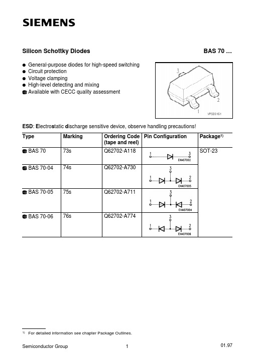
1) For detailed information see chapter Package Outlines. 2) Max. 450 mW per package. 3) Package mounted on epoxy pcb 40 mm × 40 mm × 1.5 mm/6 cm2 Cu.
TS ≤ 66 ˚C2)
BAS 70-04 … TS ≤ 40 ˚C2)
Junction temperature
Operating temperature range
Storage temperature range
Thermal Resistance
Junction - ambient3) BAS 70 BAS 70-04 …
元器件交易网
Silicon Schottky Diodes
q General-purpose diodes for high-speed switching q Circuit protection q Voltage clamping q High-level detecting and mixing
Differential forward resistance rf = f (IF) f= 10 kHz
Semiconductor Group
4
元器件交易网
Forward current IF = f (TA*; TS) * Package mounted on epoxy
Available with CECC quality assessment
BAS 70 …
ESD: Electrostatic discharge sensitive device, observe handling precautions!
INFINEON BSP135 说明书
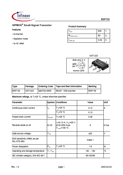
BSP135Parameter Symbol Conditions Unitmin.typ.max. Thermal characteristicsThermal resistance,junction - soldering point (pin 4)R thJS--25K/W SMD version, device on PCB R thJA minimal footprint--1156 cm2 cooling area1)--70 Electrical characteristics, at T j=25 °C, unless otherwise specifiedStatic characteristicsDrain-source breakdown voltage V(BR)DSS V GS=-3 V, I D=250 µA600--V Gate threshold voltage V GS(th)V DS=3 V, I D=94 µA-2.1-1.4-1Drain-source cutoff current I D(off)V DS=600 V,V GS=-3 V, T j=25 °C--0.1µAV DS=600 V,V GS=-3 V, T j=125 °C--10Gate-source leakage current I GSS V GS=20 V, V DS=0 V--100nA On-state drain current I DSS V GS=0 V, V DS=10 V20--mA Drain-source on-state resistance R DS(on)V GS=0 V, I D=0.01A-3060ΩV GS=10 V, I D=0.12 A-2545Transconductance g fs |V DS|>2|I D|R DS(on)max,I D=0.1 A0.080.16-SValues1) Device on 40 mm x 40 mm x 1.5 mm epoxy PCB FR4 with 6 cm2 (single layer, 70 µm thick) copper area for drain connection. PCB is vertical in still air.BSP135ParameterSymbol ConditionsUnitmin.typ.max.Dynamic characteristics Input capacitance C iss -98146pFOutput capacitanceC oss -8.513Reverse transfer capacitance C rss - 3.4 5.1Turn-on delay time t d(on)- 5.48.1ns Rise timet r - 5.68.4Turn-off delay time t d(off)-2842Fall timet f-182273Gate Charge Characteristics Gate to source charge Q gs -0.240.36nCGate to drain charge Q gd - 2.0 3.0Gate charge total Q g - 3.7 4.9Gate plateau voltage V plateau-0.20-V Reverse DiodeDiode continous forward current I S --0.12ADiode pulse current I S,pulse --0.48Diode forward voltage V SD V GS =-3 V, I F =0.12 A, T j =25 °C-0.78 1.2V Reverse recovery time t rr -87130ns Reverse recovery chargeQ rr-70104nC V R =300 V, I F =0.1 A, d i F /d t =100 A/µsT A =25 °CValues V GS =-3 V, V DS =25 V, f =1 MHzV DD =300 V, V GS =-3...5 V, I D =0.1 A, R G =6 ΩV DD =400 V, I D =0.1 A, V GS =-3 to 5 VBSP135 Package Outline:Footprint:Packaging:Dimensions in mmBSP135 Published byInfineon Technologies AGBereich KommunikationSt.-Martin-Straße 53D-81541 München© Infineon Technologies AG 1999All Rights Reserved.Attention please!The information herein is given to describe certain components and shall not be considered aswarranted characteristics.Terms of delivery and rights to technical change reserved.We hereby disclaim any and all warranties, including but not limited to warranties of non-infringement, regarding circuits, descriptions and charts started herein.Infineon Technologies is an approved CECC manufacturer.InformationFor further information on technology, delivery terms and conditions and prices, please contact your nearest Infineon Technologies office in Germany or our Infineon Technologies representatives worldwide (see address list).WarningsDue to technical requirements, components may contain dangerous substances.For information on the types in question, please contact your nearest Infineon Technologies office. Infineon Technologies' components may only be used in life-support devices or systems with the expressed written approval of Infineon Technologies if a failure of such components can reasonablybe expected to cause the failure of that life-support device or system, or to affect the safety or effectiveness of that device or system. Life support devices or systems are intended to be implantedin the human body, or to support and/or maintain and sustain and/or protect human life. If they fail,it is reasonable to assume that the health of the user or other persons may be endangered.This datasheet has been download from: Datasheets for electronics components.。
Q62702-P5059中文资料

of the solder- ble soldering
ing iron
time
300 °C
3s
Distance between solder joint and case
≥ 1.5 mm
Semiconductor Group
4
1998-09-08
SFH 4591 SFH 4592
Relative spectral emission Irel = f (λ)
Schnelle GaAlAs-IR-Lumineszenzdiode High-Speed GaAlAs Infrared Emitter
SFH 4591 SFH 4592
Area not flat
9.0
0.6 0.4
8.2
7.8 7.5
5.9 5.5
2.54 mm spacing
0.8 0.4 ø5.1 ø4.8
Symbol
Ie min Ie typ Ie typ
Werte Values
SFH 4591
SFH 4592
40
25
80
40
600
300
Einheit Unit mW/sr
mW/sr
Lötbedingungen Soldering Conditions
Tauch-, Schwall- und Schlepplötung Dip, wave and drag soldering
Symbol Symbol
Wellenlänge der Strahlung Wavelength of peak emission
IF = 100 mA, tP = 20 ms
Spektrale Bandbreite bei 50% von Imax Spectral bandwidth at 50% of Imax
BPX65

Silizium-PIN-Fotodiode Silicon PIN Photodiode Wesentliche Merkmaleq Speziell geeignet für Anwendungen im Bereich von 350 nm bis 1100 nm q BPX 65: Hohe Fotoempfindlichkeit q BPX 66: Sperrstromarm (typ. 150 pA)q Hermetisch dichte Metallbauform (TO-18),geeignet bis 125o C 1)Anwendungenq schneller optischer Empfänger mit gro βer Modulationsbandbreite Featuresq Especially suitable for applications from 350 nm to 1100 nmq BPX 65: high photosensitivityq BPX 66: low reverse current (typ. 150 pA)q Hermetically sealed metal package (TO-18),suitable up to 125o C 1)Applicationsq Fast optical sensor of high modulation bandwidth BPX 65BPX 661)Eine Abstimmung der Einsatzbedingungen mit dem Hersteller wird empfohlen bei T A> 85o C 1)For operating conditions of T A > 85o C please contact us.Typ Type Bestellnummer Ordering Code Gehäuse PackageBPX 65Q62702-P2718 A3 DIN 41870, planes Glasfenster, hermetisch dichtes Gehäuse, Lötspie βe im 2.54-mm-Raster (2/10”), Anodenkennzeichnung: Nase am Gehäuse-boden18 A3 DIN 41870, flat glass lens, hermetically sealed package, solder tabs 2.54 mm (2/10”) lead spacing, anode marking: projection at package bot-tomBPX 66Q62702-P80Ma βe in mm, wenn nicht anders angegeben/Dimensions in mm, unless otherwise specified.Grenzwerte Maximum RatingsBezeichnung Description SymbolSymbolWertValueEinheitUnitBetriebs- und LagertemperaturOperating and storage temperature rangeT op;T stg–40...+80o CLöttemperatur (Lötstelle 2 mm vomGehäuse entfernt bei Lötzeit t≤ 3s)Soldering temperature in 2 mm distancefrom case bottom (t≤ 3s)T S230o CSperrspannungReverse voltageV R50VVerlustleistung,T A = 25o CTotal power dissipationP tot250mWKennwerte(T A = 25o C, Normlicht A,T = 2856 K)Characteristics(T A = 25o C, standard light A,T = 2856 K)Bezeichnung Description SymbolSymbolWertValueEinheitUnitFotoempfindlichkeit,V R = 5 VSpectral sensitivityS10 (≥ 5.5)nA/IxWellenlänge der max. FotoempfindlichkeitWavelength of max. sensitivityλS max850nmSpektraler Bereich der FotoempfindlichkeitS = 10% von S maxSpectral range of sensitivityS = 10% of S maxλ350...1100nmBestrahlungsempfindliche FlächeRadiant sensitive areaA 1.00mm2Abmessung der bestrahlungsempfindlichen FlächeDimensions of radiant sensitive area L x BL x W1x1mmAbstand Chipoberfläche zu Gehäuseober-flächeDistance chip front to case surfaceH 2.25...2.55mmHalbwinkel Half angle ϕ±40Graddeg.Dunkelstrom Dark currentBPX 65:V R = 20 V BPX 66:V R = 1 VI R 1 (≤ 5)0.15 (≤ 0.3)nA Spektrale Fotoempfindlichkeit,λ = 850 nm Spectral sensitivityS λ0.55A/W Quantenausbeute,λ = 850 nm Quantum yieldη0.80Electrons Photon Leerlaufspannung,E v = 1000 Ix Open-circuit voltageV L 320 (≥ 270)mV Kurzschlu βstrom,E v = 1000 Ix Short-circuit currentI K 10µA Anstiegs und Abfallzeit des Fotostromes Rise and fall time of the photocurrentR L = 50Ω;V R = 5 V;λ = 850 nm;I p = 800µA t r ,t f12nsDurchla βspannung,I F = 100 mA,E = 0Forward voltageV F 1.3V Kapazität,V R = 0 V,f = 1 MHz,E = 0CapacitanceC 011pF Temperaturkoeffizient von V L Temperature coefficient of V L TC V –2.6mV/K Temperaturkoeffizient von I K Temperature coefficient of I KTC I 0.2%/K Rauschäquivalente Strahlungsleistung Noise equivalent power V R = 20 V,λ = 850 nmNEP3.3x 10–14W √Hz Nachweisgrenze,V R = 20 V,λ = 850 nm Detection limitD*3.1x 1012cm ·√Hz WKennwerte (T A = 25o C, Normlicht A,T = 2856 K)Characteristics (T A = 25o C, standard light A,T = 2856 K)Bezeichnung Description Symbol SymbolWert ValueEinheit UnitRelative spectral sensitivity S rel =f (λ)Dark current I R =f (V R ),E= 0Photocurrent I P =f (E v ),V R = 5 V Open-circuit-voltage V L =f (E v )CapacitanceC =f (V R ),f = 1 MHz,E= 0Total power dissipation P tot =f (T A )Dark currentI R =f (T A ), V R = 20 V,E= 0Directional characteristics S rel =f (ϕ)。
CMY91资料
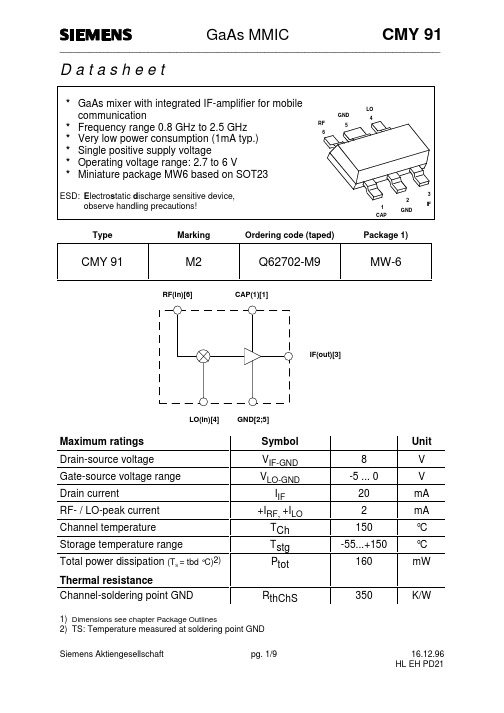
D a t a s h e e tTypeMarkingOrdering code (taped)Package 1)RF(in)[6]CAP(1)[1]IF(out)[3]LO(in)[4]GND[2;5]1)Dimensions see chapter Package Outlines2)TS: Temperature measured at soldering point GNDElectrical characteristics at T A = 25°C / V D = 3 V unless otherwise specified Characteristics of 900MHz test and application circuit (see page app. circuit)T A = 25°C / V D = 3 V; CAP-pin connected to ground by 680Ω resistorNot used ports were terminated by 50 Ω.Please make sure that LO-signal is clean of noise and spurious at f = f LO +/- f IFElectrical characteristics at T A = 25°C / V D = 3 V unless otherwise specified Characteristics of 1450MHz application circuit (see page app. circuit)T A = 25°C / V D = 3 V; CAP-pin connected to ground by 680Ω resistorNot used ports were terminated by 50 Ω.Electrical characteristics at T A = 25°C / V D = 3 V unless otherwise specified Characteristics of 1900MHz application (see page app. circuit)T A = 25°C / V D = 3 V; CAP-pin connected to ground by 680Ω resistorNot used ports were terminated by 50 Ω.900MHz measurement and application circuit (Figure 1)LO in IF out Udc=3V100pF45MHz965MHz1) Siemens SIMID 01-coil; Ordering code: B82412-A3270-M2) Optional resistor increases IF-amplifier operating current and improvesconversion gain and intermodulation performance(minimum value: 27Ω)3) Siemens SIMID 01-coil; Ordering code: B82412-A3471-K1450MHz measurement and application circuit (Figure 2) 100pF1) Tune for optimum match2) Optional resistor increases IF-amplifier operating current and improvesconversion gain and intermodulation performance(minimum value: 27Ω)3) Siemens SIMID 01-coil; Ordering code: B82412-A3221-K1900MHz measurement and application circuit (Figure 1) 100pFLO in1800MHz1) Tune for optimum match2) Optional resistor increases IF-amplifier operating current and improvesconversion gain and intermodulation performance(minimum value: 27Ω)3) Siemens SIMID 01-coil; Ordering code: B82412-A3221-MPCB - Layouts for Application Circuits900MHz - application board:Actual size20mm × 20mm1450MHz - application board:Actual size20mm × 20mmPCB - data: Glass fiber epoxy board (double sided) ε= 4.8 thickness = 1mmr1900MHz - application board:Actual size20mm × 20mm= 4.8 thickness = 1mm PCB - data: Glass fiber epoxy board (double sided) εr。
BSS81B中文资料

V(BR)EB0 6
–
Collector-base cutoff current VCB = 60 V VCB = 60 V, TA = 150 ˚C
ICB0
–
–
–
–
Emitter-base cutoff current VEB = 3 V
IEB0
–
–
DC current gain IC = 100 µA, VCE = 10 V IC = 1 mA, VCE = 10 V IC = 10 mA, VCE = 10 V1) IC = 150 mA, VCE = 10 V1) IC = 500 mA, VCE = 10 V1)
–
50
–
35
–
75
–
40
–
100 –
25
–
40
–
Collector-emitter saturation voltage1) IC = 150 mA, IB = 15 mA IC = 500 mA, IB = 50 mA
VCEsat
–
–
–
–
Base-emitter saturation voltage1) IC = 150 mA, IB = 15 mA IC = 500 mA, IB = 50 mA
BSS 79 BSS 81
Type
BSS 79 B BSS 79 C BSS 81 B BSS 81 C
Marking
CEs CFs CDs CGs
Ordering Code (tape and reel)
Q62702-S503 Q62702-S501 Q62702-S555 Q62702-S605
Pin Configuration
BF622中文资料

Permissible pulse load Ptot max/Ptot DC = f (tp)
Transition frequency fT = f (IC) VCE = 10 V, f = 20 MHz
Semiconductor Group
3
元器件交易网
DC current gain hFE = f (IC) VCE = 20 V
Semiconductor Group
2
元器件交易网
BF 622
Total power dissipation Ptot = f (TA*; TS) * Package mounted on epoxy
Output capacitance Cobo = f (VCE) f = 1 MHz
1
5.91
元器件交易网
BF 622
Electrical Characteristics at TA = 25 ˚C, unless otherwise specified.
Parameter
DC characteristics
Collector-emitter breakdown voltage IC = 1 mA IC = 10 µA, RBE = 2.7 kΩ Collector-base breakdown voltage IC = 10 µA Emitter-base breakdown voltage IE = 10 µA Collector cutoff current VCB = 200 V VCB = 200 V, TA = 150 ˚C Collector cutoff current VCE = 200 V, RBE = 2.7 kΩ VCE = 200 V, RBE = 2.7 kΩ, TA = 150 ˚C Emitter cutoff current VEB = 5 V DC current gain1) IC = 25 mA, VCE = 20 V Collector-emitter saturation voltage1) IC = 10 mA, IB = 1 mA Base-emitter saturation voltage1) IC = 10 mA, IB = 1 mA
- 1、下载文档前请自行甄别文档内容的完整性,平台不提供额外的编辑、内容补充、找答案等附加服务。
- 2、"仅部分预览"的文档,不可在线预览部分如存在完整性等问题,可反馈申请退款(可完整预览的文档不适用该条件!)。
- 3、如文档侵犯您的权益,请联系客服反馈,我们会尽快为您处理(人工客服工作时间:9:00-18:30)。
Gma
IC = 15 mA, VCE = 8 V, ZS = ZSopt ZL = ZLopt f = 900 MHz f = 1.8 GHz
Transducer gain |S21e|2 11.5 6 13.5 8 -
IC = 15 mA, VCE = 8 V, ZS =ZL= 50 Ω f = 900 MHz f = 1.8 GHz
Package Equivalent Circuit: LBI = LBO = LEI = LEO = LCI = LCO = CBE = CCB = CCE = 84 165 0.85 0.51 0.69 0.61 0 0.49 nH nH nH nH nH nH fF fF fF
Valid up to 6 GHz For examples and ready to use parameters please contact your local Siemens distributor or sales office to obtain a Siemens CD-ROM or see Internet: http://www.siemens.de/Semiconductor/products/35/35.htm
0.90551 12.196 1.2703 0.79584 0.66749 0.32167 0.21451 922.07 0.3 0.75 1.11 300
fA mA Ω V fF V eV K
0.016123 A 0.019729 A
0.024709 fA
0.013277 mA
All parameters are ready to use, no scalling is necessary. Extracted on behalf of SIEMENS Small Signal Semiconductors by: Institut für Mobil-und Satellitenfunktechnik (IMST) © 1996 SIEMENS AG
DC current gain
IC = 15 mA, VCE = 8 V
Semiconductor Group
2
Dec-13-1996
元器件交易网
BFT 92
Electrical Characteristics at TA = 25°C, unless otherwise specified. Parameter Symbol min. AC Characteristics Transition frequency Values typ. max. Unit
1.6
6.0 GHz 10V 8V
pF 5.0
Ccb
1.2
fT
4.5 4.0 1.0 3.5 0.8 3.0 2.5 0.6 2.0 0.4 1.5 1.0 0.2 0.5 0.0 0 4 8 12 16 V VR 22 0.0 0 5 10 15 20 mA IC 30 1V 0.7V 3V 2V 5V
VCEO VCBO VEBO IC IB Ptot Tj TA Tstg
1)
TS ≤ 78 °C
Junction temperature Ambient temperature Storage temperature Thermal Resistance Junction - soldering point
V(BR)CEO
15 50 -
V nA 100 µA 10 15 -
IC = 1 mA, IB = 0
Collector-base cutoff current
ICBO IEBO hFE
VCB = 10 V, IE = 0
Emitter-base cutoff current
VEB = 2 V, IC = 0
BF = IKF = BR = IKR = RB = RE = VJE = XTF = PTF = MJC = CJS = XTB = FC =
98.533 10.297 7.9562 1.5119 0.79082 0.30227 0 0.3 0 0 0.75167
Ω Ω V deg fF -
NF = ISE = NR = ISC = IRB = RC = MJE = VTF = CJC = XCJC = VJS = EG = TNOM
|S21 |2 = f(VCE):---------
Intermodulation Intercept Point IP3=f(IC)
(3rd order, Output, ZS=ZL=50Ω)
f = Parameter
16
VCE = Parameter, f = 900MHz
28
IC=15mA
dB 0.9GHz
2) Gma = |S21/S12| (k-(k2-1)1/2)
Semiconductor Group
3
Dec-13-1996
元器件交易网
BFT 92
SPICE Parameters (Gummel-Poon Model, Berkeley-SPICE 2G.6 Syntax) : Transistor Chip Data IS = 4.5354 fA VAF = NE = VAR = NC = RBM = CJE = TF = ITF = VJC = TR = MJS = XTI = 10.983 1.1172 47.577 1.206 1.5939 1.7785 32.171 1.2 2.0779 0 3 V V Ω fF ps V ns -
Power Gain Gma, Gms = f(IC)
f = 0.9GHz VCE = Parameter
16
Power Gain Gma, Gms = f(IC)
f = 1.8GHz VCE = Parameter
8.5 10V dB 5V 3V 2V
dB
10V
G
12
8V 5V 3V 2V
G
7.0 6.0 5.0
Package SOT-23
Maximum Ratings Parameter Collector-emitter voltage Collector-base voltage Emitter-base voltage Collector current Base current Total power dissipation Symbol Values 15 20 2 25 3 mW 200 150 - 65 ... + 150 - 65 ... + 150 ≤ 360 °C mA Unit V
10
8
1V
4.0 1V 3.0 2.0 0.7V 1.0 0.0
6
0.7V
4
2 0 0 5 10 15 20 mA IC 30
Байду номын сангаас
0
5
10
15
20
mA IC
30
Semiconductor Group
6
Dec-13-1996
元器件交易网
BFT 92
Power Gain Gma, Gms = f(VCE):_____
0 0.0
0.5
1.0
1.5
2.0
2.5
Semiconductor Group
7
Dec-13-1996
元器件交易网
BFT 92
PNP Silicon RF Transistor • For broadband amplifiers up to 2GHz at collector currents up to 20mA • Complementary type: BFR 92P (NPN)
ESD: Electrostatic discharge sensitive device, observe handling precaution! Type Marking Ordering Code Pin Configuration BFT 92 W1s Q62702-F1062 1=B 2=E 3=C
0 0 20 40 60 80 100 120 °C 150 TA ,TS
Permissible Pulse Load RthJS = f (tp)
Permissible Pulse Load Ptotmax/PtotDC = f (tp)
10 3
10 2
RthJS
K/W
Ptotmax/PtotDC D=0 0.005 0.01 0.02 0.05 0.1 0.2 0.5
fT
3.5 5 0.54 0.25 0.77 -
GHz pF 0.8 dB 2 3.2 -
IC = 15 mA, VCE = 8 V, f = 500 MHz
Collector-base capacitance
Ccb Cce
-
VCB = 10 V, f = 1 MHz
Collector-emitter capacitance
10 2 0.5 0.2 0.1 0.05 0.02 0.01 0.005 D=0
10 1
10 1 -7 10
10
-6
10
-5
10
-4
10
-3
10
-2
10 s 10 tp
-1
0
10 0 -7 10
10
-6
10
-5
10
-4
10
-3
10
-2
10 s 10 tp
-1
0
Semiconductor Group
Semiconductor Group
4
Dec-13-1996
