AIC2803CN中文资料
2803芯片

支持免费上传,创造良好化境。
Edited by Foxit Reader特征● 18位恒定电流输出。
℃除非有另外规定电气特性(VCC=5V, TA= 25,典型内部框图图1. WS2803内部模块框图芯片引脚设置图2.a SOP-28 图2.b DIP-28引脚功能描述到地的电阻就可以将WS2803的恒定电流输出设定在22mA 。
R EXT =1.5K 时,I OUT =18.6mAWS2803芯片的消耗功率 (PD)WS2803芯片所消耗的最大功率由PD(max)=(Tj-Ta)/Rth(j-a)决定,当所有18个输出通道均开启的时候,芯片中实际消耗的功率为。
因此,为了保证PD(act )≤PD(MAX),最大驱动电流与占空比的关系为)×××(+)×(=)(18DS OUT DD DD D V Duty I V I act P 18///)×(=)(Duty V V I R T T IDS CC CC a jth a j OUT。
当使用环境温度上升时,芯片消耗的最大功率为PD(MAX)=(Tj-Ta)/Rth(j-a),当使用环境温度上升时,芯片所允许消耗的最大功率将降低。
负载供电电压 (V LED )WS2803所设计的VDS 操作范围为0.8~5V ,考虑到芯片封装的散热效率的显示,VDS 可以升高,但是必须要保证PD(ACT)>PD(MAX),,当V LED =24V 时 and V DS =V LED -V F ,,V LED 为负载供电电压,在实际应用中最好将VLED 设定在满足输出驱动要求的最低电压。
在有必要时,需要在芯片的外部添加一个分压器,产生一个压降V DROP 来避免过多的功率消耗在芯片上,该分压器应该满足V DS =(V LED -V F )-V DROP如下图所示,电阻和齐纳二极管都可以用来降低WS2803的功耗。
A2803中文资料

NOTE: For detailed information on purchasing options, contact your local Allegro field applications engineer or sales representative.Allegro MicroSystems, Inc. reserves the right to make, from time to time, revisions to the anticipated product life cycle plan for a product to accommodate changes in production capabilities, alternative product availabilities, or market demand. The information included herein is believed to be accurate and reliable. However, Allegro MicroSystems, Inc. assumes no responsibility for its use; nor for any infringements of patents or other rights of third parties which may result from its use.Recommended Substitutions:High Voltage High Current Darlington ArraysA2803Date of status change: May 2, 2005Deadline for receipt of LAST TIME BUY orders: October 28, 2005These parts are in production but have been determined to be LAST TIME BUY . This classification indicates that the product is obsolete and notice has been given. Sale of this device is currently restricted to existing customer applications. The device should not be purchased for new design applications because of obsolescence in the near future. Samples are no longer st Time Buy2803 THRU 2824HIGH-VOLTAGE,HIGH-CURRENTDARLINGTON ARRAYS115 Northeast Cutoff, Box 15036Worcester, Massachusetts 01615-0036 (508) 853-50002Copyright © 1977, 2001 Allegro MicroSystems, Inc.*Also available for operation between -40°C and +85°C. To order, change prefix from ‘ULN’ to ‘ULQ’.DEVICE PART NUMBER DESIGNATION5075100125150AMBIENT TEMPERATURE IN °C25Dwg. GP-018BA L L O W AB L E P AC K A G E P O W E RD I S S I P A T I O N I N W A T T Sx = Character to identify specific device. Specification shown applies to family of devices with remaining digits as shown. See matrix above.The ULx2804, ULx2823, & ULx2824 are discontinued.Shown for reference only.2803 THRU 2824HIGH-VOLTAGE,HIGH-CURRENT DARLINGTON ARRAYS3Complete part number includes prefix to operating temperature range: ULN = -20°C to +85°C, ULQ = -40°C to +85°C and a suffix to identify package style: A = DIP, LW = SOIC.Types ULx2803A, ULx2803LW, ULx2804A, and ULx2804LWELECTRICAL CHARACTERISTICS at +25°C (unless otherwise noted).The ULx2804 is discontinued.Shown for reference only.2803 THRU 2824HIGH-VOLTAGE,HIGH-CURRENTDARLINGTON ARRAYS115 Northeast Cutoff, Box 15036Worcester, Massachusetts 01615-0036 (508) 853-50004Complete part number includes prefix to operating temperature range: ULN = -20°C to +85°C, ULQ = -40°C to +85°Cand a suffix to identify package style: A = DIP, LW = SOIC. Note that the ULQ2823LW and ULQ2824LW are not presently available.Types ULx2823A, ULN2823LW, ULx2824A, and ULN2824LWELECTRICAL CHARACTERISTICS at +25°C (unless otherwise noted).The ULx2823 & ULx2824 are discontinued.Shown for reference only.2803 THRU 2824HIGH-VOLTAGE,HIGH-CURRENTDARLINGTON ARRAYS115 Northeast Cutoff, Box 15036Worcester, Massachusetts 01615-0036 (508) 853-5000620Dwg. GP-070-44010080DUTY CYCLE IN PER CENT0600400O U T P U T C U R R E N T I N m A /C H A N N E L2006020Dwg. GP-070-34010080DUTY CYCLE IN PER CENT0600400O U T P U T C U R R E N T I N m A /C H A N N E L20060ALLOWABLE COLLECTOR CURRENT AS A FUNCTION OF DUTY CYCLEULx28xxLW20Dwg. GP-070-24010080DUTY CYCLE IN PER CENT 0600400O U T P U T C U R R E N T I N m A /C H A N N E L2006020Dwg. GP-070-14010080DUTY CYCLE IN PER CENT 0600400O U T P U T C U R R E N T I N m A /C H A N N E L20060ALLOWABLE COLLECTOR CURRENT AS A FUNCTION OF DUTY CYCLEULx28xxAx = Characters to identify specific device. Specification shown applies to family of devices with remaining digits as shown.2803 THRU 2824HIGH-VOLTAGE,HIGH-CURRENT DARLINGTON ARRAYS7INPUT CURRENT AS AFUNCTION OF INPUT VOLTAGEULx28x3xDwg. GP-069INPUT VOLTAGE2.52.0I N P U T C U R R E N T I N m A — II N1.00.51.50.5Dwg. GP-0671.01.5COLLECTOR-EMITTER SATURATION VOLTAGE0600400C O L L E C T O R C U R R E N T I N m A200COLLECTOR CURRENT AS A FUNCTION OF INPUT CURRENT200Dwg. GP-068400INPUT CURRENT IN µA0600400C O L L E C T O R C U R R E N T I N m A200ULx28x4x6Dwg. GP-069-11012INPUT VOLTAGE52.0I N P U T C U R R E N T I N m A — II N1.00.51.587911SATURATION VOLTAGE AS A FUNCTION OFCOLLECTOR CURRENTx = Characters to identify specific device. Characteristic shown applies to family of devices with remaining digits as shown.2803 THRU 2824HIGH-VOLTAGE,HIGH-CURRENTDARLINGTON ARRAYS115 Northeast Cutoff, Box 15036Worcester, Massachusetts 01615-0036 (508) 853-50008PACKAGE DESIGNATOR “A” DIMENSIONSDimensions in Inches (controlling dimensions)Dimensions in Millimeters (for reference only)NOTES:1.Exact body and lead configuration at vendor’s option within limits shown.2.Lead spacing tolerance is non-cumulative.3.Lead thickness is measured at seating plane or below.Dwg. MA-001-18A in19Dwg. MA-001-18A mm192803 THRU 2824HIGH-VOLTAGE,HIGH-CURRENT DARLINGTON ARRAYS9PACKAGE DESIGNATOR “LW” DIMENSIONSDimensions in Inches (for reference only)Dimensions in Millimeters (controlling dimensions)Dwg. MA-008-18A mm1.27BSCwg. MA-008-18A inBSCNOTES:1.Exact body and lead configuration at vendor’s option within limits shown.2.Lead spacing tolerance is non-cumulative.2803 THRU 2824HIGH-VOLTAGE,HIGH-CURRENT DARLINGTON ARRAYS115 Northeast Cutoff, Box 15036Worcester, Massachusetts 01615-0036 (508) 853-500010The products described here are manufactured under one or more U.S. patents or U.S. patents pending.Allegro MicroSystems, Inc. reserves the right to make, from time to time, such departures from the detail specifications as may be required to permit improvements in the performance, reliability, ormanufacturability of its products. Before placing an order, the user is cautioned to verify that the information being relied upon is current.Allegro products are not authorized for use as critical components in life-support devices or systems without express written approval.The information included herein is believed to be accurate and reliable. However, Allegro MicroSystems, Inc. assumes no responsi-bility for its use; nor for any infringement of patents or other rights of third parties which may result from its use.元器件交易网。
UCC2803DTRG4中文资料
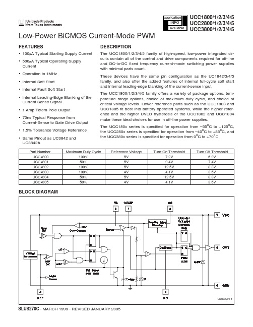
ELECTRICAL CHARACTERISTICSUnless otherwise stated, these specifications apply for –55°C ≤ TA ≤ +125°C for
UCC180x; –40°C ≤ TA ≤ +85°C for UCC280x; 0°C ≤ TA ≤ +70°C for UCC380x; VCC=10V (Note 3); RT=100k from REF to RC;
Power Dissipation at TA < +25°C (N or J Package) . . . . . 1.0W Power Dissipation at TA < +25°C (D Package). . . . . . . . 0.65W Power Dissipation at TA < +25°C (L Package) . . . . . . . 1.375W Storage Temperature Range. . . . . . . . . . . . . –65°C to +150°C
The UCC1800/1/2/3/4/5 family offers a variety of package options, temperature range options, choice of maximum duty cycle, and choice of critical voltage levels. Lower reference parts such as the UCC1803 and UCC1805 fit best into battery operated systems, while the higher reference and the higher UVLO hysteresis of the UCC1802 and UCC1804 make these ideal choices for use in off-line power supplies. The UCC180x series is specified for operation from –55oC to +125oC, the UCC280x series is specified for operation from –40oC to +85oC, and the UCC380x series is specified for operation from 0oC to +70oC.
芯片2803资料

PIN CONNECTION (top view)
April 1993
1/8
ULQ2801A - ULQ2802A - ULQ2803A - ULQ2804A - ULQ2805A
SCHEMATIC DIAGRAM AND ORDER CODES For ULQ2801A (each driver for PMOS-CMOS) For ULQ2802A (each driver for 14-15 V PMOS)
Ci Input Capacitance
tPLH Turn-on Delay Time tPHL Turn-off Delay Time
IR Clamp Diode Leakage Current
VF Clamp Diode Forward Voltage
Test Conditions
VCE = 50V TJ = 105°C, VCE = 50V TJ = 105°C for ULQ2802A VCE = 50V, Vi = 6V
Symbol Vo Vi
IC IB Ptot
Tamb Tstg
Parameter
Output Voltage Input Voltage for ULQ2802A, 2803A, 2804A
for ULQ2805A Continuous Collector Current Continuous Base Current
500 µA 1b 500 µA 1b
0.9 1.1 V 1.1 1.3 V 2 1.3 1.6 V
0.82 1.25 mA 0.93 1.35 mA 0.35 0.5 mA 3
1 1.45 mA
1.5 2.4 mA
2803芯片

2803芯片2803芯片(HT2803)是一种面向电子产品设计和嵌入式系统开发的低功耗、高性能单片机芯片。
它由Hangzhou Silan Microelectronics Co., Ltd生产,适用于家电、智能终端、工业控制和汽车电子等领域。
HT2803芯片采用先进的技术和设计,具有以下主要特点:1. 高性能:采用高速、低功耗的ARM Cortex-M3内核,频率可达80MHz,可以处理复杂的嵌入式应用程序。
此外,它还配备了丰富的外设接口,如UART、I2C、SPI等,方便与外部设备进行通信和数据交换。
2. 低功耗:HT2803芯片在设计上注重了功耗的优化。
它通过合理的功耗管理策略和低功耗模式的支持,可以将功耗降到最低,延长电池寿命,适合那些对长时间运行的电池供电设备。
3. 强大的时钟和计时功能:HT2803芯片集成了多种时钟和计时功能,包括实时时钟(RTC)、定时器(Timer)和看门狗定时器(Watchdog Timer),可以满足各种实时需求,如精确时间戳、定时中断等。
4. 多种存储和扩展能力:HT2803芯片内部集成了不同容量的Flash存储器和SRAM,可以存储大量程序代码和数据。
此外,它还拥有多个外部扩展存储接口,如SD卡接口和SPI Flash接口,方便用户根据需求扩展存储空间。
5. 强大的通信接口:HT2803芯片支持多种通信接口,包括UART、I2C、SPI和USB等。
这些通信接口可以与其他外设设备进行数据交换和通信,方便实现设备之间的互联互通。
6. 安全性保护:HT2803芯片具有丰富的安全特性,如时钟和数据加密、防篡改保护和独立的安全存储区域。
这些安全特性可以有效保护设备的安全性和数据的机密性。
综合来说,HT2803芯片是一款高性能、低功耗的嵌入式单片机芯片,适用于多种领域的电子产品设计和开发。
它的强大的功能和丰富的外设接口,可以满足各种应用需求,并保证设备的可靠性和安全性。
DSC2803X 数字信号控制器 数据手册说明书

Haawking DSC2803X数字信号控制器数据手册编号:北京中科昊芯科技有限公司2022年03月V1.3历史版本记录目录1.器件概述 (5)1.1产品特性 (5)1.2应用 (6)2.DSC28034简介 (7)2.1器件特性 (7)2.2产品编码 (8)2.3引脚分配 (9)2.4信号说明 (10)3.功能概述 (19)3.1系统架构 (19)3.2内存映射 (19)3.3简要说明 (21)3.3.1HXS320F2803x DSC (21)3.3.2内存总线 (21)3.3.3外设总线 (21)3.3.4实时JTAG和分析 (22)3.3.5闪存 (22)3.3.6M0、M1、L0、L1SARAM (22)3.3.7引导ROM (23)3.3.8.1JTAG引导模式 (23)3.3.8.2GetMode获取模式 (24)3.3.8.3引导加载器使用的外设引脚 (24)3.3.8安全性 (24)3.3.9外设中断扩展(PIE)模块 (25)3.3.10外部中断(XINT1-XINT3) (26)3.3.11内部振荡器、外部振荡器和PLL (26)3.3.12看门狗 (26)3.3.13外设时钟 (26)3.3.14低功耗模式 (27)3.3.15通用输入/输出(GPIO)复用器 (27)3.3.1632位CPU定时器(0,1,2) (28)3.3.18控制外设 (28)3.3.19串行端口外设 (29)3.4寄存器映射 (29)3.5器件仿真寄存器 (30)3.7LDO/VREG/BOR/POR (34)3.7.1VREG (34)3.7.1.1使用片上VREG (35)3.7.1.2不使用片上VREG (35)3.7.2片上上电复位(POR)和掉电复位(BOR)电路 (35)3.8系统控制 (36)3.8.1内部零引脚振荡器 (39)3.8.2晶体振荡器选项 (40)3.8.3基于PLL的时钟模块 (41)3.9低功耗模块 (41)4.外设 (43)4.1模拟器件 (43)4.1.1特性 (43)4.1.2ADC MUX多路复选 (47)4.1.3比较器模块 (47)4.2同步串行通信接口(SPI)模块 (48)4.3异步串行通信接口(SCI)模块 (51)4.4本地互联网络(Lin)模块 (53)4.5增强型控制器局域网络(eCAN)模块 (55)4.6内部集成电路接口(I2C)模块 (58)4.7增强型PWM模块(ePWM1/2/3/4/5/6/7) (61)4.8高分辨率PWM模块(HRPWM) (63)4.9增强型脉冲捕获模块(eCAP) (64)4.10高分辨率脉冲捕获模块(HRCAP) (66)4.11增强型正交编码器模块(eQEP) (67)4.12JTAG端口 (72)4.13GPIO控制寄存器 (74)4.14直接存储访问存储单元(DMA) (78)5.开发支持 (83)5.1集成开发环境Haawking IDE (83)5.2仿真器 (84)5.2.1简介 (84)5.2.2概览 (84)5.2.2.1特性 (85)5.3串口下载器 (86)5.4JTag下载工具 (87)6.1绝对最大额定值 (88)6.2推荐工作条件 (88)6.3ESD额定值 (89)6.4电气特性 (89)6.5功耗 (91)6.6散热设计考虑 (92)7.热特性/机械数据 (93)7.1LQFP80 (93)7.2TQFP64 (94)8.参考文献 (95)1.器件概述1.1产品特性高能效32位处理器(H28x内核)✓主频120MHz(周期8.33ns)✓哈佛(Harvard)总线架构✓硬件乘法/除法单元✓4/6通道高速DMA✓快速中断响应和处理✓统一存储器编程模型✓高效代码(使用C/C++和汇编语言)增强型控制外设✓增强型脉宽调制器(ePWM)✓高分辨率PWM(HRPWM)✓增强型捕获(eCAP)✓高分辨率输入捕获(HRCAP)✓增强型正交编码器脉冲(eQEP)✓模数转换器(ADC)✓片载温度传感器✓比较器芯片及系统开销✓3.3V单电源供电✓无上电顺序要求✓集成上电和掉电复位✓代码安全模块✓无模拟支持引脚时钟和系统控制✓两个内部12MHz零引脚振荡器✓片载振荡器/外部时钟输入✓看门狗定时器模组功能✓支持锁相环路(PLL)倍频系数动态调整多达45个具有输入滤波功能、可单独编程的多路复用GPIO✓可支持所有外设中断的外设中断扩展(PIE)模块✓三个32位CPU定时器✓每个ePWM模块中包含独立的32位定时器✓片载存储器✓闪存,SRAM,OTP,引导ROM可用128位安全密钥/锁✓保护安全内存块✓防止固件逆向工程✓串行端口外设✓一个SCI(UART)模块✓两个SPI模块✓一个内部集成电路(I2C)总线✓一个本地互连网络(LIN)总线✓一个增强型控制器局域网络(eCAN)总线高级仿真特性✓分析和断点功能✓封装选项✓80引脚薄型四方扁平(LQFP)封装✓64引脚TQFP封装✓温度选项✓工作温度:-40°至105°1.2应用●电器●医疗、保健与健身●楼宇自动化●电机驱动器●电动汽车、混合动力电动汽车(EV/HEV)动力传动●电力传送●工厂自动化●电信基础设施●电网基础设施●2.DSC28034简介2.1器件特性表2-1DSC2803x产品特性(1):ADC主频=30MHz时,转换速率是1.56Msps,由于可以同时采样转换两个通道,故最高速率为3.12Msps。
CS1258系列AFE用户手册v02

CS1258 芯片用户手册带24bits ADC 和BIM 的高性能AFEREV0.2 通讯地址:深圳市南山区蛇口南海大道1079 号花园城数码大厦A座9楼邮政编码:518067公司电话:+(86 755)86169257传真:+(86 755)86169057公司网站:CS1258 芯片用户手册版本历史修改记录日期0.1 预览版本2016/3/15 0.2 .更新了电气特性2016/3/29.更新了典型应用图.更新了封装图目录版本历史 (2)目录 (3)图目录 (5)表目录 (5)1 简介 (6)1.1 主要特性 (6)1.2 应用场合 (6)1.3 功能说明 (6)1.4 极限值 (8)1.5 电气特性 (9)1.6 可靠性指标 (10)1.7 产品型号及引脚 (11)1.8 典型应用电路 (12)2 功能寄存器说明 (13)2.1 功能寄存器列表 (13)2.2 功能寄存器说明 (13)2.2.1 SYS —系统配置寄存器 (13)2.2.2 ADC0— ADC 配置寄存器 (14)2.2.3 ADC1— ADC 配置寄存器1 (14)2.2.4 ADC2— ADC 配置寄存器2 (15)2.2.5 ADC3— ADC 配置寄存器3 (15)2.2.6 ADC4— ADC 配置寄存器4 (16)2.2.7 ADC5— ADC 配置寄存器5 (16)2.2.8 BIM0— BIM 配置寄存器0 (17)2.2.9 BIM1— BIM 配置寄存器 (17)2.2.10 ADO— ADC 转换数据寄存器 (18)2.2.11 ADS— ADC 转换数据读取标准寄存器 (18)3 功能描述 (19)3.1 输入选择 (19)3.2 输入电平移位器 (19)3.3 IDAC1/IDAC0 和输入通道 (20)3.4 PGA 和ADC (21)3.5 数字滤波器 (23)3.5.1 频率响应 (23)3.5.2 建立时间 (23)3.6 人体阻抗测量 (25)3.6.1 正弦信号发生器 (25)3.6.2 激励电极及测量电极 (26)3.6.3 整流 (26)3.6.4 阻抗校准 (27)3.7 参考电压源 (28)3.8 内部时钟源 (28)3.9 温度传感器 (28)3.10 测量模式及其切换 (28)3.11 多种工作模式 (29)3.12 复位和断电(POR&power down) (30)4 转换有效位 (31)5 典型特性 (32)5.1 ADC 典型特性 (32)5.2 LDO/VREF 典型特性 (32)5.3 内部时钟典型特性 (32)5.4 IDAC 典型特性 (32)5.5 BIM 典型特性 (32)6 三线串行通讯接口 (37)6.1.1 读时序 (38)6.1.2 写时序 (38)7 封装 (40)图目录图 1.1 CS1258 原理框图 (7)图 1.2 CS1258 引脚图 (11)图 1.3 CS1258 典型应用电路 (12)图 3.1 模拟输入结构图 (19)图 3.2 电平移位模块 (20)图 3.3 IDAC1/IDAC0 结构及与输入通道关系 (20)图 3.4 PGA 和ADC 结构图 (21)图 3.5 COMB 滤波器的频率响应特性(Fs=331Hz,DR=10Hz,3 阶COMB) (23)图 3.6 COMB 建立过程 (24)图 3.7 BIM 模块结构图 (25)图 3.8 CS1258 低功耗工作示意图 (29)图 5.1 内部时钟全电压全温度范围的典型特性 (32)图 5.2 FWR 模式下220 欧姆纯电阻网络的测试结果 (33)图 5.3 FWR 模式下1000 欧姆纯电阻网络的测试结果 (33)图 5.4 FWR 模式下1958 欧姆纯电阻网络的测试结果 (34)图 5.5 FWR+MIX 模式510ohm+470pF 并联网络的阻抗绝对值测试结果 (34)图 5.6 FWR+MIX 模式510ohm+470pF 并联网络的相位角测试结果 (35)图 5.7 FWR+MIX 模式1018Ohm+10nF 并联网络的阻抗绝对值测试结果 (35)图 5.8 FWR+MIX 模式1018Ohm+10nF 并联网络的相位角测试结果 (36)图 6.1 读操作时序1(读AD 值) (38)图 6.2 读操作时序2(除AD 值之外的寄存器) (38)图 6.3 写操作时序 (39)图7.1 芯片LQFP32 封装尺寸信息(天水) (40)表目录表 1.1 CS1258 极限值 (8)表 1.2 CS1258 电气特性 (9)表 1.3 CS1258 引脚说明 (11)表 2.1 功能寄存器列表 (13)表 2.2 SYS 寄存器说明 (13)表 2.3 ADC0 寄存器说明 (14)表 2.4 ADC1 寄存器说明 (14)表 2.5 ADC2 寄存器说明 (15)表 2.6 ADC3 寄存器说明 (15)表 2.7 ADC4 寄存器说明 (16)表 2.8 ADC5 寄存器说明 (16)表 2.9 BIM0 寄存器说明 (17)表 2.10 BIM1 寄存器说明 (17)表 4.1 ADC 信号链不同GAIN 及DR 下的有效位(ENOB)1) (31)表 6.1 串口通讯命令列表 (37)表 6.2 三线串行通讯接口时序表 (39)版权所有,侵权必究芯海科技(深圳)股份有限公司第 5 页,共40 页1 简介1.1 主要特性◆输入●支持单端输入●支持组成多个差分输入对●支持输入电平移位功能◆PGA●1/2/4/8/16/32/64/128 倍可选增益●高达100Mohm 的等效输入阻抗◆BIM●支持4/6/8 电极测量●支持5K/10K/25K/50K/100K/250KHz 多档频率测量●支持阻抗绝对值和相角测量◆ADC●24 bit 分辨率●输出速率10~1280Hz 8 档可选◆有效位● 2.35V 参考、40Hz 速率、128 倍增益下19.5bits 有效位◆LDO 及内部参考电压●自带LDO,输出2.35/2.45/2.8/3.0V 可选,精度±1%●自带低漂移基准,内部参考电压2.048V 可选,精度±1%◆支持性能、普通、低功耗、休眠模式◆支持电压测量、温度测量、BIM 测量及手动测量模式,单命令切换◆低漂移片上时钟◆三线串行通讯1.2 应用场合桥式传感器四角平衡称重压力检测人体阻抗分析交流测脂1.3 功能说明CS1258 原理框图如图1 所示。
MA801_MA802_A9
6. 存储器组织................................................................................................... 19
7. 数据指针寄存器(DPTR)................................................................................ 23 8. 系统时钟 ...................................................................................................... 24
2012/11 version A9
2
MA801_MA802 1 中央处理器 MA801_MA802 8K 字节 Flash ROM ━ ISP 存储空间可以选择 1.0KB, 2.0KB 或 3.0KB ━ 用于 Flash 存储器访问的两级代码保护 ━ Flash 写/擦除周期: 20,000 ━ Flash 数据保留时间: 在 25℃下 100 年 片上 256 字节暂存 RAM 中断控制器 ━ 7 个中断源,4 级优先级 ━ 两个外部中断输入,INT0 和 INT1 两个 16 位定时/计数器, Timer 0 和 Timer 1. ━ Timer 0/1 可以选择 X12 模式 可编程的 16 位计数/定时阵列(PCA) 支持 2 通道 PWM ━ 捕获模式 ━ 16 位软件定时器模式 ━ 高速输出模式 ━ 8 位 PWM 模式 增强型 UART (S0) ━ 帧错误检测 ━ 自动地址识别 8 位 ADC ━ 可编程吞吐率达到 100 ksps ━ 8 通道单端输入 主/从 SPI 串行接口 可编程看门狗定时器,由 CPU 或上电一次使能。 在 20 脚封装下最多 15 个 GPIO。 ━ 可以配置成双向口,推挽输出,漏极开路和仅输入 多种电源控制模式:空闲模式和掉电模式 ━ 所有中断可以唤醒空闲模式 ━ 2 个源可以唤醒掉电模式 低压侦测器:对于 MA801 是 VDD 3.7V ,对于 MA802 是 VDD 2.4V 工作电压范围 Operating voltage range: ━ MA801: 4.5V~5.5V, 要求 Flash 写操作最小是 4.5V (ISP/IAP) ━ MA802: 2.4V~3.6V, 要求 Flash 写操作最小是 2.7V (ISP/IAP) 工作频率范围: 25MHz(最大) ━ MA801: 0 – 25MHz @ 4.5V – 5.5V ━ MA802: 0 – 12MHz @ 2.4V – 3.6V and 0 – 25MHz @ 2.7V – 3.6V 时钟源 ━ 外部晶振模式和内置 RC 振荡器 (IRCO, 6MHz) 工作温度: ━ 工业级 (-40℃ to +85℃)* 封装类型: ━ PDIP20: MA801AE/MA802AE ━ SOP20: MA801AS/MA802AS ━ TSSOP20: MA801AT/MA802AT
LTC2803中文资料

ABSOLUTE MAXIMUM RATINGS
(Note 1)
Input Supplies
VCC........................................................... –0.3V to 7V VL.......................................................... –0.3V to 6.7V Generated Supplies
These parts are compatible with the TIA/EIA-232-F standard. Driver outputs are protected from overload and can be shorted to ground or up to ±15V without damage. To extend battery life, receivers can be kept active, operating at reduced speed, with only 15μA current. In shutdown mode, current is further reduced to 1μA. Line sharing and half-duplex operation are also supported.
11 TIN
10 VL 13
9 MODE
8 PS
VEE
7 CAP
DE PACKAGE 12-LEAD (4mm s 3mm) PLASTIC DFN
TJMAX = 125°C, θJA = 43°C/W, θJC = 4.3°C/W (4 Layer) EXPOSED PAD (PIN 13) IS VEE, MUST BE SOLDERED TO PCB
M283核心板产品简介

3
北京分公司
北京市海淀区知春路 108 号豪景大厦 A 座 19 层 电话:(010)62536178 62635573
上海分公司:南京
南京市珠江路 280 号珠江大厦 1501 室 电话:(025)6Байду номын сангаас123923 68123920
深圳分公司
深圳市福田区深南中路 2072 号电子大厦 12 楼 电话:(0755)83640169 83783155
1
M283 工控核心板
硬件资源
处理器:ARM926 MCIMX283/ MCIMX283 RISC 处理器 Cache:16KB 指令 Cache,16KB 数据 Cache 系统内存:128MB SDRAM (32 位总线接口) 电子硬盘:256MB NAND Flash (用户可用空间为 160MB) SD 卡接口:1 个 SD 卡接口,支持热插拔 SD 卡 以太网接口:1 路 10/100M 以太网接口 USB 接口: USB Host 接口 1 个 (USB 2.0)、 USB OTG 接口 1 个 (USB 2.0) RS-232 串口:3 个,其中 2 个为功能串口,1 个为调试串口 显示接口:LCD 接口,支持 TFT 液晶屏(4.3V/5V),最大分辨率 800x480 通用数字 I/O:7 路(3.3V) 电源接口:直流输入 DC 5.0V ADC 接口:4 路 12 位 120KHz 其它:四线电阻式触摸屏接口、 2 个 LED 灯、外置独立看门狗定时器、机械尺寸 45mm×60mm
订购信息
类别 核心板 核心板 核心板 核心板 核心板 核心板 评估套件 液晶套件
型号 M283-128I M283-128WI M283-128LI M287-128I M287-128WI M287-128LI EasyARM-iMX283
UCC2803QDREP资料

元器件交易网IMPORTANT NOTICETexas Instruments Incorporated and its subsidiaries (TI) reserve the right to make corrections, modifications,enhancements, improvements, and other changes to its products and services at any time and to discontinueany product or service without notice. Customers should obtain the latest relevant information before placingorders and should verify that such information is current and complete. All products are sold subject to TI’s termsand conditions of sale supplied at the time of order acknowledgment.TI warrants performance of its hardware products to the specifications applicable at the time of sale inaccordance with TI’s standard warranty. Testing and other quality control techniques are used to the extent TIdeems necessary to support this warranty. Except where mandated by government requirements, testing of allparameters of each product is not necessarily performed.TI assumes no liability for applications assistance or customer product design. Customers are responsible fortheir products and applications using TI components. To minimize the risks associated with customer productsand applications, customers should provide adequate design and operating safeguards.TI does not warrant or represent that any license, either express or implied, is granted under any TI patent right,copyright, mask work right, or other TI intellectual property right relating to any combination, machine, or processin which TI products or services are used. Information published by TI regarding third–party products or servicesdoes not constitute a license from TI to use such products or services or a warranty or endorsement thereof.Use of such information may require a license from a third party under the patents or other intellectual propertyof the third party, or a license from TI under the patents or other intellectual property of TI.Reproduction of information in TI data books or data sheets is permissible only if reproduction is withoutalteration and is accompanied by all associated warranties, conditions, limitations, and notices. Reproductionof this information with alteration is an unfair and deceptive business practice. TI is not responsible or liable forsuch altered documentation.Resale of TI products or services with statements different from or beyond the parameters stated by TI for thatproduct or service voids all express and any implied warranties for the associated TI product or service andis an unfair and deceptive business practice. TI is not responsible or liable for any such statements.Mailing Address:Texas InstrumentsPost Office Box 655303Dallas, Texas 75265Copyright 2003, Texas Instruments Incorporated。
ME2803中文资料(2015版)

Units
-VDET -VDET(S)>2.2V VHYS VIN=2V (1.0V-1.5V) VIN =3.5V (1.6V-2.5V)
V
V
Supply Current
ISS
VIN=4.5V (2.6V-3.9V) VIN =6V (4.0V-5.6V) VIN=7V (5.7V-6.5V) -
V02
Page 3 of 11
ME2803
Functional Description:
1、 When input voltage (VIN) rises above detect voltage (–VDET), output voltage (VOUT) will be equal to VIN. 2、 When input voltage (VIN) falls below detect voltage (–VDET), output voltage (VOUT) will be equal to the ground voltage (GND) level. 3、 When input voltage (VIN) falls to a level below that of the minimum operating voltage (VMIN), output will become unstable. In this condition, V IN will equal the pulled-up output (should output be pulled-up.) 4、 When input voltage (VIN) rises above the ground voltage (GND) level, output will be unstable at levels below the minimum operating voltage (VMIN). Between the VMIN and detect release voltage +VDET) levels, the ground voltage (GND) level will be maintained. 5、 When input voltage (VIN) rises above detect release voltage (+VDET), output voltage (VOUT) will be equal to VIN. 6、 The difference between +VDET and –VDET represents the hysteresis range.
LED升压恒流驱动ICAP2803
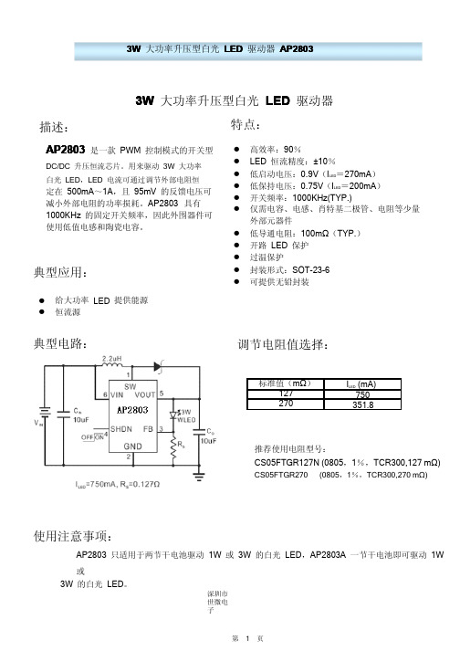
典型电路:
调节电阻值选择:
标准值(mΩ) 127 270
ILED (mA) 750 351.8
推荐使用电阻型号: CS05FTGR127N (0805,1%,TCR300,127 mΩ) CS05FTGR270 (0805,1%,TCR300,270 mΩ)
过温迟滞
OTH
最大输出电流
IMAX
750
静态电流
IQ
ILED=0mA,Vout=3.4V, 开关频率:1000KHz
关断电流
ISD
关断模式
开关导通电阻
RDSON
Vout=3.4V
电流门限
ILIM
Vout=3.4V
2
效率
η
注:VF为 LED 的正向电压
ILED=750mA
95 0.9 0.75 1000
使用注意事项:
AP2803 只适用于两节干电池驱动 1W 或 3W 的白光 LED,AP2803A 一节干电池即可驱动 1W
或 3W 的白光 LED。
深圳市 世微电 子
第1页
3W 大功率升压型白光 LED 驱动器 AP2803 Ver04
引脚排列图:
引脚分配:
SOT-23-6
引脚号
1 2 3 4 5 6
极限参数:
符号
SW GND FB SHDN VOUT VIN
功能
开关引脚 地
反馈端 关断引脚 电压输出端 电压输入端
参数
符号
输入脚电压VINFra bibliotek开关脚电压
SW
XL2803A 500mA Darlington Array IC说明书

8C 7C 6C 5C 4C 3C 2C7B6B5B4B3B2B1BCOM8B1CXL2803A SOP181Features•500-mA-Rated Collector Current (Single Output)•High-Voltage Outputs:50V •Output Clamp Diodes•Inputs Compatible With Various Types of Logic2Applications•Relay Drivers •Hammer Drivers •Lamp Drivers•Display Drivers (LED and Gas Discharge)•Line Drivers •Logic Buffers •Stepper Motors •IP Camera•HVAC Valve and LED Dot MatrixPART NUMBER PACKAGE BODY SIZE (NOM)XL2803ASOIC (18)11.55mm ×7.50mmLogic Diagram4Device Information (1)TTL or 5-V CMOS devices.for each Darlington pair for operation directly with XL2803A device has a 2.7-k Ωseries base resistor discharge),line drivers,and logic buffers.The lamp drivers,display drivers (LED and gas Applications include relay drivers,hammer drivers,be connected in parallel for higher current capability.Darlington pair is 500mA.The Darlington pairs may inductive loads.The collector-current rating of each common-cathode clamp diodes for switching Darlington pairs that feature high-voltage outputs with transistor array.The device consists of eight NPN The XL2803A device is a 50V,500mA Darlington 3Description1B 1C 2B 2C 3B 3C 4B 4C 5B 5C 6B 6C 7B 7C 8B 8C GNDCOM5Pin Configuration and FunctionsDW Package 18-Pin SOIC Top ViewPin FunctionsPINTYPEDESCRIPTIONNAME NO.1B 1IChannel 1through 8Darlington base input2B 23B 34B 45B 56B 67B 78B 81C 18OChannel 1through 8Darlington collector output2C 173C 164C 155C 146C 137C 128C 11GND 9—Common emitter shared by all channels (typically tied to ground)COM10I/OCommon cathode node for flyback diodes (required for inductive loads)(1)Stresses beyond those listed under Absolute Maximum Ratings may cause permanent damage to the device.These are stress ratings only,which do not imply functional operation of the device at these or any other conditions beyond those indicated under Recommended Operating Conditions .Exposure to absolute-maximum-rated conditions for extended periods may affect device reliability.(2)All voltage values,unless otherwise noted,are with respect to the emitter/substrate terminal GND.6Specifications6.1Absolute Maximum Ratingsat 25°C free-air temperature (unless otherwise noted)(1)MINMAX UNIT V CE Collector-emitter voltage 50V V I Input voltage (2)30V Peak collector current 500mA I(clamp)Output clamp current500mA Total substrate-terminal current –2.5A T J Junction temperature –65150°C T stg Storage temperature–65150°C(1)JEDEC document JEP155states that 500-V HBM allows safe manufacturing with a standard ESD control process.(2)JEDEC document JEP157states that 250-V CDM allows safe manufacturing with a standard ESD control process.6.2ESD RatingsVALUEUNIT V (ESD)Electrostatic dischargeHuman body model (HBM),per ANSI/ESDA/JEDEC JS-001(1)±2000VCharged device model (CDM),per JEDEC specification JESD22-C101(2)±5006.3Recommended Operating Conditionsover operating free-air temperature range (unless otherwise noted)MINMAX UNIT V CE Collector-emitter voltage 050V T AAmbient temperature–4085°C(1)For more information about traditional and new thermal metrics,see the Semiconductor and IC Package Thermal Metrics application report.6.4Thermal InformationTHERMAL METRIC (1)UNITDW (SOIC)18PINS R θJA Junction-to-ambient thermal resistance 66.4°C/W R θJC(top)Junction-to-case (top)thermal resistance 29.5°C/W R θJB Junction-to-board thermal resistance 33.0°C/W ψJT Junction-to-top characterization parameter 6.0°C/W ψJB Junction-to-board characterization parameter 32.5°C/W R θJC(bot)Junction-to-case (bottom)thermal resistanceN/A°C/W XL2803A6.5Electrical Characteristicsat T A=25°C free-air temperature(unless otherwise noted)PARAMETER TEST CONDITIONS UNITMIN TYP MAXI CEX Collector cutoff current V CE=50V,see Figure3I I=050μAI I(off)Off-state input current V CE=50V,T A=70°CI C=500μA,see Figure45065μAI I(on)Input current V I=3.85V,See Figure50.93 1.35mAV I(on)On-state input voltage V CE=2V,see Figure6I C=200mA 2.4VI C=250mA 2.7I C=300mA3V CE(sat)Collector-emitter saturation voltage I I=250μA,see Figure7I C=100mA0.9 1.1V I I=350μA,see Figure7I C=200mA1 1.3I I=500μA,see Figure7I C=350mA 1.3 1.6I R Clamp diode reverse current V R=50V,see Figure850μA V F Clamp diode forward voltage I F=350mA see Figure9 1.72V C i Input capacitance V I=0,f=1MHz1525pF6.6Switching CharacteristicsT A=25°CPARAMETER TEST CONDITIONS MIN TYP MAX UNITt PLH Propagation delay time,low-to high-level output VS =50V,C L=15pF,R L=163Ω,See Figure10130nst PHL Propagation delay time,high-to low-level output20V OH High-level output voltage after switching V S=50V,I O=300mA,see Figure11V S–20mV 6.7Typical CharacteristicsXL2803AOpenVOpenVIOpenVIOpen V I CI CEXOpen7Parameter Measurement InformationFigure 3.I CEX Test CircuitFigure 4.I I(off)Test CircuitFigure 5.I I(on)Test CircuitFigure 6.V I(on)Test CircuitFigure 7.h FE ,V CE(sat)Test CircuitFigure 8.I R Test CircuitFInputOpenΩOutputV IH(see Note C)Test CircuitVoltage WaveformsV OHA.The pulse generator has the following characteristics:PRR =12.5kHz,Z O =50Ω.B.C L includes probe and jig capacitance.C.V IH =3VFigure 10.Propagation Delay TimesOutputTest Circuit(see Note C)V OHVoltage WaveformsA.The pulse generator has the following characteristics:PRR=12.5kHz,Z O=50Ω.B.C L includes probe and jig capacitance.C.V IH=3Vtch-Up TestCOMOutput CEInput B8.2Functional Block Diagramthe outputs.Applications requiring sink currents beyond the capability of a single output may be accommodated by paralleling solutions to a great many interface needs,including solenoids,relays,lamps,small motors,and LEDs.operation directly with TTL or CMOS operating at supply voltages of 5V or 3.3V.The XL2803A offers diodes for inductive loads.The XL2803A has a series base resistor to each Darlington pair,thus allowing a common emitter and open collector outputs.To maximize their effectiveness,these units contain suppression The XL2803A is comprised of eight high voltage,high current NPN Darlington transistor pairs.All units feature integration of 8Darlington transistors that are capable of sinking up to 500mA and wide GPIO range capability.This standard device has proven ubiquity and versatility across a wide range of applications.This is due to its 8.1Overview8Detailed Descriptionsupplies are used,connect to the highest voltage supply.When driving resistive loads,COM can be left unconnected or connected to the load voltage supply.If multiple 8.4.2Resistive Load Drivekick-back voltage through the internal free wheeling diodes.When the COM pin is tied to the coil supply voltage,XL2803A is able to drive inductive loads and suppress the 8.4.1Inductive Load Drive8.4Device Functional Modespins.forward biased,internal parasitic NPN transistors will draw (a nearly equal)current from other (nearby)device In normal operation,the diodes on base and collector pins to emitter will be reverse biased.If these diode are coils causes a reverse current to flow into the coil supply through the kick-back diode.inductive load that is excited when the NPN drivers are turned off (stop sinking)and the stored energy in the The diodes connected between the output and COM pin are used to suppress the kick-back voltage from an base of the predriver Darlington NPN.The GPIO voltage is converted to base current through the 2.7-k Ωresistor connected between the input and very-low input current,essentially equating to operation with low GPIO voltages.of a single transistor with a very-high current gain.The very high βallows for high output current drive with a Each channel of XL2803A consists of Darlington connected NPN transistors.This connection creates the effect 8.3Feature Description9Application and Implementation9.1Application InformationXL2803A will typically be used to drive a high voltage and/or current peripheral from an MCU or logic device that cannot tolerate these conditions.The following design is a common application of XL2803A,driving inductive loads.This includes motors,solenoids,and relays.Each load type can be modeled by what is seen in Figure12.9.2Typical ApplicationFigure12.XL2803A as Inductive Load Driver()J(MAX)A (MAX)JATT PD -=q ND OLi Lii 1P V I ==´åTypical Application (continued)9.2.1Design RequirementsFor this design example,use the parameters listed in Table 1as the input parameters.Table 1.Design ParametersDESIGN PARAMETEREXAMPLE VALUEGPIO voltage 3.3or 5V Coil supply voltage 12to 50VNumber of channels 8Output current (R COIL )20to 300mA per channelDuty cycle100%where•T J(MAX)is the target maximum junction temperature.•T A is the operating ambient temperature.•θJA is the package junction to ambient thermal resistance.(3)number of coils possible,use Equation 2to calculate XL2803A on-chip power dissipation P D .The number of coils driven is dependent on the coil current and on-chip power dissipation.To determine the 9.2.2.3Power Dissipation and TemperatureElectrical Characteristics .The output low voltage (V OL )is the same thing as V CE(SAT)and can be determined by Figure 1,Figure 2,or 9.2.2.2Output Low VoltageI COIL =(V SUP –V CE(SAT))/R COIL(1)V CE(SAT)).The coil current is determined by the coil voltage (VSUP),coil resistance,and output low voltage (V OL or 9.2.2.1Drive Current•Power dissipation •Output and drive current •Temperature range•Input voltage range When using XL2803A in a coil driving application,determine the following:9.2.2Detailed Design Procedureto the maximum allowable power dissipation (P D )dictated by Equation 3.To ensure the reliability of XL2803A and the system,the on-chip power dissipation must be lower that or equal •V OLi is the OUT i pin voltage for the load current I Li .This is the same as V CE(SAT)(2)•N is the number of channels active together.where11.2Layout ExampleFigure 15.Package Layoutand R COIL =2.8k ΩThe following curves were generated with XL2803A driving an OMRON G5NB relay –V in =5.0V;V sup =12V 9.2.3Application Curveswide.Some applications require up to 2.5A.Because all of the channels currents return to a common emitter,it is best to size that trace width to be very material's current density and desired drive current.for the output,in order to drive high currents as desired.Wire thickness can be determined by the trace care to separate the input channels as much as possible,as to eliminate crosstalk.TI recommends thick traces Thin traces can be used on the input due to the low current logic that is typically used to drive XL2803A.Take 11.1Layout Guidelines11Layoutchip metal or overheating the part.heavily forward bias the flyback diodes and cause a large current to flow into COM,potentially damaging the on-When this is the case,make sure that the output voltage does not heavily exceed the COM pin voltage.This will This part does not need a power supply;however,the COM pin is typically tied to the system power supply.10Power Supply Recommendations12。
28035调CAN
28035调CAN1)邮箱初始化配置:首先应确定从32个邮箱中选择要配置的目标邮箱,比如配置成发送邮箱或接收邮箱,一般是成对出现的。
然后是对靠近的邮箱进行ID号(标识符)的配置,数据长度,优先级的设置,是远程帧还是普通扩展数据帧等。
具体步骤总结如下:第一步在写标识符前必须将所有邮箱屏蔽掉,ECanaRegs.CANME.all=0。
(第五步,最后将要用到的邮箱配置好后,使能需要用到的邮箱,比如邮箱0和邮箱16,ECanaRegs.CANME.bit.ME0=1;ECanaRegs.CANME.bit.ME16=1;)第二步:通过向寄存器CANMC的CDR位请求改变数据区,该位允许快速更新数据消息。
再第五步的时候,需要将该位写0,CPU请求正常操作。
第三步,设置邮箱的ID(标识符,发送邮箱对应的接收邮箱的标识符是一致的,这个需注意),数据方向寄存器配置了发送邮箱还是接收邮箱。
数据长度,发送优先级的设置,以及是否有远方应答帧的请求,向邮箱RAM区写数据(这个注意:ECanaboxes.MBOXO.MDRL.all=?ECanaboxes.MBOXO.MDRH.all=?)2)邮箱初始化之后,就可以对其进行发送或者接收操作啦!前面第一步主要是前奏,现在进入主题。
消息的发送操作,分为五步:第一步:清除CANTRS发送请求置位寄存器---当邮箱n准备发送时,CPU将TRSn置1,启动发送。
就相当于一个开关一样,当数据要被发送时,将开关TRSn闭合,则数据发送出去。
上电复位,各位都被清0。
接着配置发送响应寄存器CANTA,如果邮箱n中的消息已经发送成功,则相应的TAn将置位。
CPU通过向TANTA中的位写1,使其复位。
如果已经产生中断,向CANTA寄存器写1,则可以清除中断,向CANTA寄存器写0没有影响。
上电后,寄存器所有的位都被清除。
第二步:初始化邮箱,见第一部分。
第三步:设置TRS请求发送标志,请求发送消息第四步:等待传输响应位置位,邮箱完成发送。
上海交大方菱数控切割机--数控平面切割控制系统(Ver2.3)操作手册
方菱数控切割机控制系统使用手册(Ver 2.3)(型号:F2300)上海交亿数控设备有限公司2010-10使用注意事项阅读手册本说明书适用于上海交亿数控设备有限公司生产的F2300型数控切割控制系统。
使用前请认真阅读该使用说明书和当地安全条例。
注意:本产品的设计不适合现场维护,如有任何维护要求,请返回上海交亿数控设备有限公司售后服务(维修)中心:地址:上海市紫竹科技园紫日路609号电计大楼201室电话:021-******** 34290970 传真:021-********E-mail:support@环境要求●本数控系统适宜工作在环境温度为-10℃至60℃,相对湿度0-95%无凝结。
●工作电压为DC +24V。
●本控制器应当安装在具有保护粉尘的控制台外壳内。
●本系统最好在远离高压高频等高辐射性的场合使用。
维护●手脚远离运动的机器,控制操作或手动可以通过前面板键盘进行。
●操作机器时不能穿宽松的衣服及有线绳之类的服饰,以防被机器缠住。
●该设备应该且只能由受过培训的人操作。
●不是本公司授权的技术人员,严禁自主拆缷机器。
●使用时,切勿溅泼酸性、碱性、腐蚀性等物品到本控制系统上。
高压电●电击能伤人致死。
必须按照装箱件规定步骤及要求进行安装。
●电源接通时,不能接触电线及电缆。
●该设备应该且只能由受过培训的人操作。
目录方菱数控切割机控制系统 (I)使用手册(VER 2.3) (I)阅读手册............................................................................................................................................. I II 环境要求............................................................................................................................................. I II 维护..................................................................................................................................................... I II 高压电................................................................................................................................................. I II第一章概述 (1)1.1系统简介 (1)1.2系统特点 (2)1.3技术指标 (3)1.4系统接口 (3)1.5硬件配置 (4)第二章系统开机 (5)2.1系统操作面板说明 (5)2.2系统启运及主界面说明 (5)2.3主界面功能索引 (8)第三章切割功能 (9)3.1切割操作索引 (11)3.2调速 (12)3.2.1 正常调速 (12)3.2.2 快速调速 (12)3.3前进 (12)3.4后退 (12)3.5边缘切割/偏移切割/返回 (12)3.6回参功能 (13)3.7氧燃气预热时间调整 (15)3.8选穿孔点 (16)3.9动态放大 (17)3.10退出切割 (17)第四章部件选项 (19)4.1XY镜像 (19)4.2角度校正 (20)4.2.1 钢板校正 (20)4.2.2 输入角度 (21)4.3重复排列 (21)4.4比例缩放 (25)4.5选行选号 (26)4.5.1 选行 (27)4.5.3 选行选号后的操作 (29)4.6图形还原 (30)第五章手动功能 (31)5.1点动功能 (31)5.2连动功能 (31)5.3定长移动功能 (32)5.4断点恢复 (32)第六章文件管理 (34)6.1硬盘文件 (34)6.2优盘文件 (35)6.3新建文件 (37)6.4代码编辑 (38)6.5编译代码 (38)第七章参数设置 (39)7.1常用参数 (39)7.2氧燃气参数 (40)7.3等离子参数 (42)7.4喷粉参数 (44)7.5系统参数 (45)7.6参数导入 (46)7.7参数导出 (47)7.8保存参数 (47)第八章诊断功能 (48)8.1诊断界面索引 (49)8.2输入诊断 (49)8.3输出诊断 (49)8.4键盘诊断 (50)8.5系统自检 (51)8.6日期时间 (52)8.7系统定义 (53)8.7.1 参数备份、还原 (53)8.7.2 输入口定义 (54)8.7.3输出口定义 (54)8.7.4坐标定义 (55)第九章图形管理 (57)9.1选择图形 (57)9.2片/孔尺寸 (58)第十章代码说明 (60)10.1编程符号及说明 (60)10.3G代码说明 (60)10.4M代码说明 (65)第十一章接口说明 (67)11.1输入接口 (67)11.1.1 输入接线说明 (69)11.1.2 遥控输入 (70)11.2输出接口 (71)11.2.1 输出接线说明 (72)11.3电机接口 (77)11.3.1电机接口典型接线图 (78)第十二章BIOS使用 (81)12.1系统升级 (82)12.2欢迎界面升级 (82)12.3运动控制升级 (82)12.4运动备份 (82)12.5系统还原 (82)第十三章安装调试 (83)13.1横/纵向脉冲数设置 (83)附录1G、M代码快速查阅 (84)第一章概述1.1 系统简介F2300型数控系统是在本公司吸收国内外诸多数控系统的优点,结合起来本公司F2100、F2200和F2500,F3100,F5100系列数控系统,开发出的一款更加人性化、操作更加简便、性价比更优的产品。
UCC28060中文资料共11页

UCC28060中文资料为降低EMI减小BULK电容及其电压纹波, 交互式PFC在功率大于300W 时具有明显优势,UCC28060即为此设计的新品,特点如下:●很容易作相位管理,仍满足轻载的效率标准。
●两相都有由检测输出电压做的防止OVP故障的功能。
●无需检测电流整形,简化了PCB布局,提高了效率。
●消除了输出整流器的反向恢复损耗,防止了MOSFET导通时的冲击电流。
UCC28060组成系统后具有下列优点:●低成本高效率,比单相CCM型更具有柔性。
●输入滤波及输出电容电流互补对消。
减小了纹波电流,减小了EMI滤波器的尺寸。
●可用低成本升压二极管,不用R-C吸收回路。
●改善了轻载效率,改善了瞬态响应。
此款控制器可用于200W~1000W的AC/DC。
它扩展了CRM的应用区间,降低了成本,整个系统加入了布朗保护,输出的OVP﹑开环﹑过载保护,并有软起动,相位错开检测及热关断保护。
其共有16PIN,功能如下:AGND 6PIN。
模拟地。
外接模拟信号旁路电容,补偿元件及模拟信号的回归点。
然后以单一点接功率地,以隔开大电流的噪声。
COMP 5PIN。
误差放大器的输出。
其为跨导放大器。
此输出是一个高阻抗源,接到电压调整器的环路补偿元件,即接于此端到GND。
栅驱动输出的导通时间正比于此端电压再减去125mV的偏移。
在软起动中,COMP端被拉低,通常仅工作在软起动之后。
在故障时,COMP端放电到0.5V以下。
电路将以低的COMP电压和短的时间重新起动,不要将COMP接到低阻抗源,这会使其出现故障。
CS 10PIN。
电流检测输入,接到电流检测电阻和整流桥的负端。
电流检测电阻的回流端用独立轨迹接到模拟地。
随着电流的增大,CS上的电压在增高,变得更负。
这个逐个周期式过流保护限制输入电流,它去关断两路栅驱动脉冲。
此时CS的电压会超出-200mV阈值,输出保持低电平直到CS端降回-15mv阈值。
电流检测信号被消隐100ns,跟随每个GD脉冲的下降沿。
28335的I2C数据手册翻译
10 位地址格式与 7 位地址格式的类似的, 但是 10 位地址格式下主机的地址 发送分两次发送,首字节数据包括:11110B, 10 位地址高两位,R/W=0(写) 。 第二个字节数据是 10 位从机地址的低 8 位,从机必须在每个字节数据后面 发送一个应答信号,一旦主机向从机发送完第二个字节数据后,主机可以写数据 或者使用循环起始信号模式改变数据流向。 更详尽的细节可以参考飞利浦公司的 I2C 总线协议。 写 1 到 XA 位选择 10 位地址模式,但是选择的时候必须确保关闭全数据格 式(FDF=0)。 2.5.3 全数据格式 在这种格式下,紧随起始信号的首字节数据字节为数据,而非从机地址。 应 答信号的发生规则与上面的格式一致。然而,这种格式下要求发送方与接收方都 要支持全数据格式,而且数据必须由始至终都是发送。 写 1 到 FDF 位选择全数据格式,全数据格式在 I2C 模块自测模式下不可以 使用。 2.5.4 循环起始信号 在每个数据帧发送结束以后主机可以发送另一个起始信号。利用这种功能, 一个主机可以在不放弃总线控制权 (不发送停止信号) 的情况下与多个从机通信。 BC 位可以选择 1 到 8 位的数据长度,循环起始信号发送可以在以上三种格式下 使用。
数据寄存器和fifo为cpu和sda暂时保存接收数据和发送数据一根外围总线使能cpu存取i2c模块寄存器和fifo一个同步时钟使得i2c输入时钟与scl上时钟同步并且同步不同主机之间的数据发送速率一个分频器对输入时钟分频后提供给i2c模块在sda与scl引脚上都有一个噪声滤波器一个仲裁机制处理i2c模块与其他主机之间的冲突中断逻辑因此中断事件可以向cpu发出中断请求fifo中断逻辑因此fifo的存取可以与数据的接收发送同步下图为28335i2c模块内部框图在非fifo模式下有四个寄存器用于数据的发送与接收
2803的工作原理
2803的工作原理
2803是一种工作原理以及相关的工作方式,它可以在不同的
应用中实现不同的功能。
下面将详细介绍2803的工作原理。
2803的工作原理基于其内部的电路设计。
当外部电源加电时,电流将流经电路。
在这个过程中,2803的内部电路将产生一
个电压,在不同的应用中,这个电压可以被用来控制其他电子元件的工作。
具体地说,在2803的内部电路中,有许多输出引脚,每个输
出引脚对应一个控制信号。
当一个输出引脚被激活时,它将提供一个高电平信号。
通过这些输出引脚,2803可以控制其他
电子元件的开关、亮度、速度等属性。
为了实现这个控制功能,2803内部还有一些驱动电路,这些
电路可以将输入信号转换为输出信号。
当输入信号满足一定的条件时,驱动电路将激活特定的输出引脚,从而实现对其他元件的控制。
总的来说,2803的工作原理是通过接收外部电源的供电,在
内部电路中产生控制信号,并通过输出引脚将这些信号传递给其他电子元件,从而实现对它们的控制。
需要注意的是,2803的具体工作原理可能因不同的应用而有
所不同。
它可以与其他电子元件结合使用,如LED、电机、
继电器等,并且其工作状态可以根据具体需求进行配置和调整。
这使得2803在工程和电子设备中具有广泛的应用前景。
- 1、下载文档前请自行甄别文档内容的完整性,平台不提供额外的编辑、内容补充、找答案等附加服务。
- 2、"仅部分预览"的文档,不可在线预览部分如存在完整性等问题,可反馈申请退款(可完整预览的文档不适用该条件!)。
- 3、如文档侵犯您的权益,请联系客服反馈,我们会尽快为您处理(人工客服工作时间:9:00-18:30)。
SPEC NO: DS-2803-00
FEATURES
Improved Replacement for ULN2803. Fast Turn-on and Turn-off.
TTL/CMOS Compatible.
APPLICATIONS
Stepping Motor Driver. Relay Driver. LED Driver.
Solenoid Driver.
TYPICAL APPLICATION CIRCUIT
DESCRIPTION
M
anufactured with the standard bipolar process, the AIC2803 is a high-voltage, high-current 8-channel Darlington array, with each of the output transistors capable of sinking peak load current of 500mA and capable of withstanding at least 50V in the OFF state.
T
he AIC2803 has a 2.7K Ω series base resistor to each Darlington pair and thus allows operation di-rectly with TTL or CMOS logic circuitry operating at a supply voltage of 5V. Outputs of the drivers can be paralleled for higher load current capability. These make the AIC2803 ideally suited for numerous in-terface between low-level logic circuitry and high-power peripheral loads, particularly those beyond the capabilities of standard logic buffers. Typical loads
include relays, solenoids, stepping motors, heaters,multiplexed LED, and incandescent displays.
T he AIC2803 features open collector outputs and integral diodes for inductive load transient suppres-sion.
ORDERING INFORMATION
AIC2803XX
PACKAGE TYPE N:PLASTIC DIP
TEMPERATURE RANGE C= 0°C~70°C
SPEC NO: DS-2803-00 ABSOLUTE MAXIMUM RATINGS(at Ta=25°C)
O utput Voltage (50V)
I nput Voltage (30V)
C ontinuous Collector Current ..................................................……………...........500mA
C ontinuous Base Current ..............................................................,,,,,,,,,,,,.........25mA
P ower Dissipation, (One Darlington Pair) .........................................,,,,,,,,,,,......... 1.0W
(Total Package) .............................,,……….................. 2.25W
O perating Ambient Temperature Range .........................…………............ -20°C~ 85°C
S torage Temperature Range ..................................…………...........-65°C~ 150°C
ELECTRICAL CHARACTERISTICS (Ta=25°C, unless otherwise specified.) P ARAMETERS T EST CONDITIONS S YMBOL M IN.T YP.M AX.U NIT
O utput Leakage Current V CE=50V,Ta=25°C
V CE=50V,Ta=70°C, Fig. 1I CEX30
100
µA
µA
C ollector-Emitter S aturation Voltage I C=100mA,I B=250µA
I C=200mA,I B=350µA
I C=350mA,I B=500µA , Fig. 2
V CE(SAT)0.8
0.9
1.0
1.1
1.3
1.5
V
V
V
I nput Current V IN=3.85V, Fig. 3
I C=500µA,Ta=70°C, Fig. 4I IN(ON)
I IN(OFF)50
0.93
65
1.35m A
µA
I nput voltage V CE=2.0V, I C=200mA
V CE=2.0V, I C=250mA
V CE=2.0V, I C=300mA, Fig. 5V IN(ON)2.3
2.4
2.5
V
V
V
I nput Capacitance C IN1525p F
C lamp Diode
L eakage Current V R=50V, Ta=25°C
V R=50V, Ta=70°C, Fig. 6
I R30
100
µA
µA
C lamp Diode
F orward Voltage I F=350mA
F ig. 7
V F1.41.8V
T urn-On Delay0.5 V IN to 0.5 V OUT, Fig. 8T ON0.10.5µS T urn-off Delay0.5 V IN to 0.5 V OUT, Fig. 8T OFF0.20.8µS
SPEC NO: DS-2803-00
TEST CIRCUITS
Fig. 1
Fig. 2
Fig. 3
Fig. 4
Fig. 5
Fig. 6
SPEC NO: DS-2803-00
TEST CIRCUITS (CONTINUED)
OUT
Fig. 8
SWITCHING DELAY
Time (nS)
V I N (V )
V O U T (V
)
200400600800
1000
020
40
60
Test Circuit of Fig. 8
ALLOWABLE AVERAGE POWER
DISSIPATION
00.5
1
1.5
2
2.5
25
50
75
100
125
150
Ambient Temperature (°C)
P o w e r D i s s i p a t i o n (W )
SPEC NO: DS-2803-00
DRIVER CIRCUIT
COM CX
INX
PHYSICAL DIMENSIONS
18 LEAD PLASTIC DIP
UNIT: mm。
