SIMOTICS S-1FL6 伺服电机
S7-200_SMART 系统手册

SIMATICS7-200 SMART2013 年 10 月版 S7-200 SMART 系统手册更新信息产品信息S7-200 SMART 文档更新概述尽管我们力求确保产品文档条理清楚与准确无误,但《S7-200 SMART 系统手册》中的一些页面仍包含不完整、不正确或误导性的信息。
使用 AXISx_ABSPOS 子例程从 SINAMICS V90 伺服驱动器读取绝对位置以下几部分提供了如何在项目中使用 AXISx_ABSPOS 子例程从 SINAMICS V90 伺服驱动器读取绝对位置的更多信息:●AXISx_ABSPOS 子例程 (页 1)●用法示例 (页 3)●互连详细信息 (页 4)●影响互操作性的调试问题 (页 4)AXISx_ABSPOS 子例程当您在“从驱动器读取绝对位置”(Read Absolute Position from Drive) 对话框中选中“启用”(Enabled) 复选框并单击“生成”(Generate) 按钮以构建向导生成的子例程时,STEP 7-Micro/WIN SMART 的运动控制向导将创建 AXISx_ABSPOS 子例程。
© Siemens AG 2013. 保留所有权利AXISx_ABSPOS 子例程的接口和参数说明如下所示:输入/输出数据类型2013 年 10 月版 S7-200 SMART 系统手册更新信息AXISx_ABSPOS 和 AXISx_LDPOS 子例程用法示例在 START 参数开启的情况下执行 AXISx_ABSPOS 子例程时,仅当成功完成该子例程后(Done 参数 = ON 且 Error 参数=“无错误”),绝对位置才有效。
在 START 输入关闭的情况下执行子例程时,由于 Error 和 D_Pos 参数会恢复为默认值,因此在完成子例程后,您必须将指令包含在您的程序中,以捕获有效的绝对位置值。
2013 年 10 月版 S7-200 SMART 系统手册更新信息互连数字量 I/O请参见SINAMICS V90/SIMOTICS S-1FL6 操作说明文档中的“PLC 连接示例”部分,以查找有关 S7-200 SMART CPU 和 V90 伺服驱动器之间的数字量控制信号连接的建议接线图。
如何解决西门子V90高性能伺服

如何解决西门子V90高性能伺服
西门子V90伺服驱动系统作为SINAMICS驱动系列家族的新成员,与SIMOTICS S-1FL6 完美结合,组成最佳的伺服驱动系统,实现位置控制、速度控制和扭矩控制。
通过优化的设计,SINAMICS V90确保了卓越的伺服控制性能,经济实用、稳定可靠。
SIMOTICS家族新成员1FL6设计卓越,制作精良,为简单伺服应用提供可靠产品。
西门子V90单轴伺服驱动V90设计用于运动控制以满足一般的伺服应用,充分考虑了机床制造商和系统集成商所面临的成本和市场挑战。
V90支持即插即用式调试,伺服性能充分优化,与SIMATIC PLC快速集成,具有值得信赖的可靠性。
与全新的SIMOTICS S-1FL6伺服电机配套使用,形成最佳的伺服系统。
V90支持内部设定值位置控制、外部脉冲位置控制、速度控制和扭矩控制,整合了脉冲输入、模拟量输入/输出、数字量输入/输出以及编码器脉冲输出接口。
通过实时自动优化和自动谐振抑制功能,可以自动优化为一个兼顾高动态性能和平滑运行的系统。
此外,脉冲输入最高支持1MHz,充分保证了高精度定位。
SINAMICS V-ASSISTANT 调试工具
一款可以通过标准USB接口连接至V90的PC软件工具,可进行参数设置、系统优化、试运行、排障和监控(如跟踪与测量功能)等相关操作。
西门子V90特点低成本
1、集成所有控制模式:外部脉冲位置、内部设定值位置、速度和转矩控制;
2、全功率驱动标配内置制动电阻;
3、集成抱闸继电器。
伺服性能优异
1、自动优化功能使设备获得更高的动态性能
2、自动抑制机械谐振频率
3、1 MHz 的高速脉冲输入。
关于回转窑轮带间隙测控及筒体温度

Ts 为筒体垫板外径处的温度,℃;Tro 为轮带的平均温度,
℃;T1 为安装时的环境温度,℃。
窑工作状态下(即热态下),轮带内圆与筒体垫板
外圆在直径方向上的实际间隙为:
Δ 热 =2δ1-2δ2
(2)
设计时,在理想状态下,应有 Δ 热 =2δ1-2δ2=0,
即 δ1=δ2。考虑安装方便和窑内热工制度,要求热态
Copyright©博看网. All Rights Reserved.
中国设备工程 2023.01 (下)
73
Research and Exploration 研究与探索·工艺流程与应用
V90PN 在立体仓库堆垛机中的应用研究
李立夫 (广州市殡葬服务中心,广东 广州 510630)
摘要:目前,市面上立体仓库堆垛机多采用可编程控制器(PLC)和变频器控制技术来实现对堆垛机在水平、垂直、货叉伸缩 3 个 方向上的定位控制,鉴于此,本文介绍了在立体仓库堆垛机的设计中采用伺服系统应用技术的可行性,着重分析了堆垛机位置控制的方法 及改进措施。本系统采用西门子 SIMATIC S7-1200 PLC 通过组态工艺对象(TO),使用 SINAMICS V90PN 伺服驱动器的速度控制方式来实现 定位控制功能。
堆垛机的运动控制采用的是伺服系统。 那么,什么是伺服系统呢?通常来讲,伺服系统是 具有负反馈的闭环自动控制系统。一个完整的伺服控制 系统包括以下设备:控制器、伺服驱动器、伺服电机以 及反馈装置。在本控制系统中,控制器采用的是西门子 S7-1215C PLC,驱动器采用的是西门子 SINAMICS V90 带有 PROFINET 接口的驱动器,伺服电机采用的是与 V90 PN 配套使用的 1FL6 伺服电机,反馈装置就是电机上所 带的编码器。系统主要元件明细表见表 1。 (1)1 台 S7-1215C PLC 通过 PROFINET 网络,使用 轴工艺对象(TO)控制 5 台 V90PN 的启动和停止,5 台 V90PN 工作在速度模式,使用 3 号标准报文。5 台 V90PN 分别为水平方向(X 方向)2 台,垂直方向(Y 方向)2, 货叉伸缩方向(Z 方向)1 台。
S7-1200 PLC应用基础课件第8章 PLC应用系统设计实例
8.1.2 PLC选型和资源配置
2. 电气原理图
根据所选变频器、CPU及扩展单 元型号,参照用户手册,绘制主 电路和辅助电路电气原理图,分 为电源、主电路、系统配置、 CPU 和 模 拟 量 输 入 / 输 出 等 , 如 图 8-3~ 图 8-7 所 示 , 需 要 注 意 的 是,每张图纸都应该有标题栏。 电源部分考虑控制柜散热风扇及 照明、插座等,PLC电源和24V 直流电源前面加滤波器。主电路 电气原理图中应把变频器需要设 置的主要参数标注在图纸上,本 例选择SINAMICS V20变频器
主速度设定可以采用拨码开关输入给PLC的数字量输入模块或采用电位器输入给模拟量输入模 块或采用人机界面,本例采用人机界面。变频器本身的模拟量输出可用于显示或监测频率、电 流、转矩等参数,本例变频器的模拟量输出直接输入到PLC的模拟量输入模块来检测转矩值, 两转矩值经PLC运算后通过PLC模拟量输出模块调节变频器的频率。
1. SIMATIC S7-1200 PLC S7-1200 PLC可以通过多种方式来控制伺服驱动器,最常用的是PROFIdrive方式、 PTO方式以及模拟量方式。如果采用PTO方式,则需要配有板载高速输入输出的 DC/DC/DC型CPU;若选择继电器输出型CPU,则需要专门增配具有高速数字输出的 信号板。 本例采用PROFIdrive方式,它是一种基于PROFIBUS(或PROFINET)总线的驱动技 术标准,收录于国际标准IEC61800-7中。PROFIdrive定义了一个运动控制模型,包含 多种设备,设备之间通过报文进行数据交换,这些报文就是PROFIdrive的消息帧。 每一个消息帧都要符合统一规定的标准结构。PROFIdrive消息帧功能强大,它可以 将控制字、状态字、设定值和实际值传输到相应的设备。
S7-200 SMART PLC读取1FL6伺服电机的绝对值编码器数值
8/CN/view/zh/99521584目录1概况 (3)2使用的硬件及软件 (3)2.1硬件2.2软件3实现方法 (3)3.1概述3.2实现步骤3.3接线3.4 PLC组态及编程4参考资料 (9)1 概况SINAMICS V90是西门子推出的一款小型、高效便捷的伺服系统。
它作为 SINAMICS 驱动系列家族的新成员,与SIMOTICS S-1FL6 伺服电机完美结合,组成最佳的伺服驱动系统,实现位置控制、速度控制和扭矩控制。
目前1FL6电机有两种编码器类型,即增量编码器类型及绝对值编码器类型。
西门子的小型自动化S7-200 SMART PLC可以控制V90驱动器,本文介绍如何实现SMART PLC读取1FL6伺服电机的绝对值编码器数值。
关于如何实现SMART PLC控制V90实现定位控制请参见《SIMATIC S7-200 SMART 系统手册》及《S7-200 SMART连接SINAMICS V90 实现位置控制》。
2使用的硬件及软件2.1硬件序号设备名称 订货号1 PS207电源24 V DC/2.5 A6EP1 332-1LA00CPUST60 6ES7288-1ST60-0AA0 S7-200SMART2 SIMATIC3 V90驱动器6SL3210-5FE10-4UA04 伺服电机1FL6042-1AF61-0LG15 V90 动力电缆(含接头)6FX3002-5CL01-1AD06 伺服电机编码器电缆6FX3002-2DB10-1AD0 (含接头,用于绝对值编码器)电缆线)6SL3260-4NA00-1VB0针接头及1m7 V90控制信号电缆(含508 SIMATIC Field PG M36ES7715-1BB23-0AA1USB电缆9 Mini2.2软件序号说明1 Window 7 旗舰版32位2 STEP 7-Micro/WIN SMART 编程软件3 SINAMICS_V-ASSISTANT3实现方法3.1概述如图1所示,使用PG通过标准mini USB电缆与V90连接,打开SINAMICS V—ASSITANT 软件设置驱动器的参数。
SINAMICS V90 伺服驱动系统与 SIMOTICS S-1FL6 伺服电机说明书

伺服电机合作代理商021-********/180********2目录伺服驱动系统SINAMICS V90 伺服驱动和 SIMOTICS S-1FL6 伺服电机组成了性能优化,易于使用的伺服驱动系统,八种驱动类型,七种不同的电机轴高规格,功率范围从0.05kW 到7.0kW 以及单相和三相的供电系统使其可以广泛用于各行各业,如:定位,传送,收卷等设备中,同时该伺服系统可以与S7-1500T/S7-1500/S7-1200 进行完美配合实现丰富的运动控制功能。
伺服驱动系统概述 ..................................................03伺服驱动系统优点 ..................................................05SINAMICS V90 伺服驱动系统 的自动化环境 ......................................................... 10SINAMICS V-ASSISTANT 调试工具 ..........................10SINAMICS V90 技术数据与控制特征 .......................12系统一览及接线图 ..................................................15SIMOTICS S-1FL6 技术数据 及扭矩/速度曲线 .................................................... 18SINAMICS V90 和 SIMOTICS S-1FL6 安装尺寸及安装间距 ............................................... 22选型步骤 ...............................................................26SINAMICS V90 和 SIMOTICS S-1FL6 订货数据 (27)3脉冲序列版本 (PTI)PROFINET 版本 (PN)SINAMICS V90 伺服驱动SINAMICS V90 根据不同的应用分为两个版本:1. 脉冲序列版本(集成了脉冲,模拟量,USS/MODBUS )2. PROFINET 通讯版本SINAMICS V90 脉冲版本可以实现内部定位块功能,同时具有脉冲位置控制,速度控制,力矩控制模式。
V90选型手册
脉冲串输入通道1: 5 V 差分高速脉冲输入
脉冲串输入通道2: 24 V 脉冲输入
转速限制 M
转矩限制 M
24 V +
PTIA_D+
1
PTIA_D-
2
PTIB_D+
26
PTIB_D-
27
P TI _ A _ 24P
36
P TI _ A _ 24M
37
PTI_B_24P
38
PTI_B_24M
39
12V 18
典型应用 • 装卸机:如码垛机 • 包装机:如贴标机、枕式包装机 • 自动组装机 • 刀具切换机 • 印刷机:如丝网印花机 • 缠绕机 • 金属成型机:如折弯机
5
低成本
高度集成的设计以降低系统成本
集成多种控制模式 V90 集成了外部脉冲位置控制、内部设定值位 置控制、速度控制和扭矩控制等模式。 不同的控制模式适用于多种应用场合。
2
SINAMICS 家族为各种场合提供最佳的驱 动应用
• SINAMICS 系列家族适用于各种驱动应用 • 超宽功率范围,覆盖从 0.12 kW 至 120 MW • 既适用于低压供电,也适用于中压供电 • 标准功能可适用于通用硬件和软件平台 • 具有高度的组合灵活性 SINAMICS V90 作为 SINAMICS 驱动系列家族的新成员,与 SIMOTICS S-1FL6 完 美 结 合, 组 成 最 佳 的 伺 服 驱 动 系 统, 实 现 位 置 控 制、 速 度 控 制 和 扭 矩 控 制。 通 过 优 化 的 设 计, SINAMICS V90 确保了卓越的伺服控制性能,经济实用、稳定 可靠。
接线灵活 方便快捷
V90 提供丰富全面的接口,每种控制模式都具有默认的接口定义,能满足各种应用需求,方便使用 ;而对于有特殊要求或个 性设置的应用,用户可以根据需要对接口进行重新定义。在保证标准应用方便性的同时,也为特殊应用提供了灵活性。 下图所示为脉冲串指令速度控制模式(PTI)下的默认接口定义,符合标准的应用习惯。
S7-1200CPU 1217C通过PROFINET 连接 V90伺服系统实现位置闭环控制
S7-1200CPU 1217C通过PROFINET 连接SINAMICS V90伺服系统实现位置闭环控制1摘要本文主要介绍了如何使用CPU 1217C通过PROFINET 连接SINAMICS V90伺服系统实现位置闭环控制。
其中对S7-1200 V4.0、V4.1固件版本的运动控制功能、工艺对象的组态和V90 PN的相关参数设置作了简要介绍。
2简介2.1S7-1200运动控制功能2.1.1S7-1200 V3.0 固件S7-1200 CPU固件版本从V3.0开始已经支持最多4路PTO输出,以CPU1214C (6ES7214-1AG31-0XB0)为例,其CPU本体支持4路PTO输出,其中PTO 1、PTO 2的频率范围为 2 Hz ≤ f ≤ 100 kHz,PTO 3 、PTO 4的频率范围为2 Hz ≤ f ≤ 20 kHz。
2.1.2S7-1200 V4.0 固件S7-1200 CPU V4.0固件版本虽然也只支持4路PTO输出,但是PTO的信号类型可以进行选择,支持的信号类型见表2-1 PTO 信号类型所示。
表2-1 PTO信号类型V4.0固件版本的CPU高速脉冲信号发生器输出地址可以自由分配给PTO,输出地址分配与输出频率范围见表2-2 脉冲信号发生器地址分配所示。
表2-2 脉冲信号发生器地址分配以CPU1214C CPU本体输出地址(6ES7214-1AG40-0XB0)为例,示例几种可能的PTO信号类型组合方式,见表2-3 脉冲方向组态所示:●示例1:4-100KHz PTO,不带方向输出。
●示例2:2-100KHz PTO 和 2-30KHz PTO,脉冲A+方向B输出。
●示例3:4-100KHz PTO,脉冲A+方向B输出,其中脉冲A100KHz,方向B 30KHz。
表2-3 脉冲方向组态2.1.3S7-1200 V4.1 固件S7-1200 CPU V4.1固件版本不仅支持通过PTO输出方式对伺服电机进行开环控制,而且支持通过PROFIdrive或者模拟量输出(AQ)方式对伺服电机进行闭环控制,见表2-4驱动器连接方式所示。
西门子运动控制系统.

生产机械制造行业的范例- SIMOTIONSIMOTION是一个全新的西门子运动控制系统,它是世界上第一款针对生产机械而设计的控制系统,将运动控制,逻辑控制及工艺控制功能集成于一身,为生产机械提供了完整的解决方案。
机械运动越来越复杂,对速度及精度的要求也越来越高。
SIMOTION面向的行业主要是包装机械,橡塑机械,锻压机械,纺织机械,以及其他生产机械领域,正是针对复杂运动控制而推出的全新运动控制系统。
SIMOTION运动控制系统:∙由一个系统来完成所有的运动控制任务∙适用于具有许多运动部件的机器SIMOTION系统具有三个组成部分∙工程开发系统工程开发系统可以实现由一个系统解决所有运动控制、逻辑及工艺控制的问题,并且它还能够提供所有必要的工具,从编程到参数设定,从测试调试到故障诊断。
∙实时软件模块这些模块提供了众多的运动控制及工艺控制功能。
针对某一特定的机器所需的功能,灵活地选择相关的模块。
∙硬件平台硬件平台是SIMOTION运动控制系统的基础。
使由工程开发系统所开发的且使用了实时软件模块的应用程序可以运行在不同的硬件平台上,用户可以选择最适合自己机器的硬件平台。
SIMOTION的不同之处在于,可按任务层次划分的系统,具有灵活的功能,且使用同一种工程开发工具。
SIMOTION 运动控制系统可连接三种硬件平台,即:∙SIMOTION D-集成在驱动器中的紧凑型系统。
SIMOTION D的功能是集成在新的SINAMICS S120多轴驱动系统的控制模板上。
使之成为一个极其紧凑的拥有控制器及驱动器的系统。
将运动控制与驱动器功能集成在一起,使得系统具有极快的响应速度。
o典型应用领域根据其紧凑的设计,以及集成于驱动器上这一特点,SIMOTION D特别适用于:▪小型机械▪分布式自动化结构,例如拥有多轴的机器▪模块化设计的机器,也可以与SIMOTION P或SIMOTION C配合使用▪实时性要求极高的多轴耦合应用∙SIMOTION C -模块化与灵活性SIMOTION C230-2控制器是装配在S7-300机壳中。
西门子变频器SINAMICS V90点动控制简介
西门子变频器SINAMICS V90点动控制简介西门子变频器SINAMICS V90支持内部设定值位置控制,外部脉冲位置控制,速度控制,扭矩控制;并且集合了脉冲输入,模拟量输入,模拟量输出,数字量输入,数字量输出和编码器脉冲输出的各类接口。
为实现用户的控制需求实现方便快速的连接方式,可以更好的与西门子PLC进行集成,组成一套完整的控制系统。
在实际调试过程中,点动操作是常见的一种控制方式,本文下面对这款变频器的点动控制做一个介绍,为用户在使用时提供参考。
西门子变频器SINAMICS V90在使用过程中,用户可以通过操作面板进行点动控制,但有时会出现点动控制异常,原因及解决方法如下:1. 无法点动控制原因西门子变频器SINAMICS V90通过操作面板进行点动控制,如果无法进行,可能原因有:(1)V-Assist调试软件处于在线状态;(2)伺服使能命令SON处于激活状态,即SON = 1;(3)部分条件未能满足,例如:EMGS信号处于低电平状态;驱动器处于故障状态,并且具有故障代码;硬件连接未完成;2. 解决方法西门子变频器SINAMICS V90在通过面板操作时,如果不能进行点动控制,可以参照如下的方法进行解决:(1)保持V-Assist软件处于离线状态;(2)去掉伺服使能命令,即SON = 0;(3)满足其他所需条件,例如:保持EMGS信号为高电平,即EMGS = 1;排除设备当前故障,根据要求完成硬件的连接。
西门子变频器SINAMICS V90具有经济性好,伺服性能高,操作简单,运行稳定的特点。
并且和SIMOTICS S-1FL6 伺服电机配套使用,可以组成理想的伺服控制系统,应用在印刷机,包装机等设备上。
用户在调试过程中,如果需要通过控制面板对设备进行点动控制时,可以参考本文中的说明进行操作并且合理配置。
SIMOTICS S-1FL6 伺服电机

WARNING
Danger to life due to fire if overheating occurs because of insufficient ventilation clearances Inadequate ventilation clearances can cause overheating of components with subsequent fire and smoke. This can cause severe injury or even death. This can also result in increased downtime and reduced service lives for devices/systems. • Ensure compliance with the specified minimum clearance
• Ground the device in compliance with the applicable regulations.
© Siemens AG 2013-2015
WARNING
Danger to life due to electric shock when opening plug connections in operation When opening plug connections in operation, arcs can result in severe injury or death. • Only open plug connections when the equipment is in a
WARNING
Danger to life through a hazardous voltage when connecting an unsuirious injury can result when live parts are touched in the event of a fault. • Only use power supplies that provide SELV (Safety Extra
SMART 200读取1FL6伺服电机的绝对值编码器数值
SMART 200读取1FL6伺服电机的绝对值编码器数值(一)概况SINAMICS V90是西门子推出的一款小型、高效便捷的伺服系统。
它作为SINAMICS 驱动系列家族的新成员,与SIMOTICS S-1FL6 伺服电机完美结合,组成最佳的伺服驱动系统,实现位置控制、速度控制和扭矩控制。
目前1FL6电机有两种编码器类型,即增量编码器类型及绝对值编码器类型。
西门子的小型自动化S7-200 SMART PLC 可以控制V90 驱动器,本文介绍如何实现SMART PLC 读取1FL6 伺服电机的绝对值编码器数值。
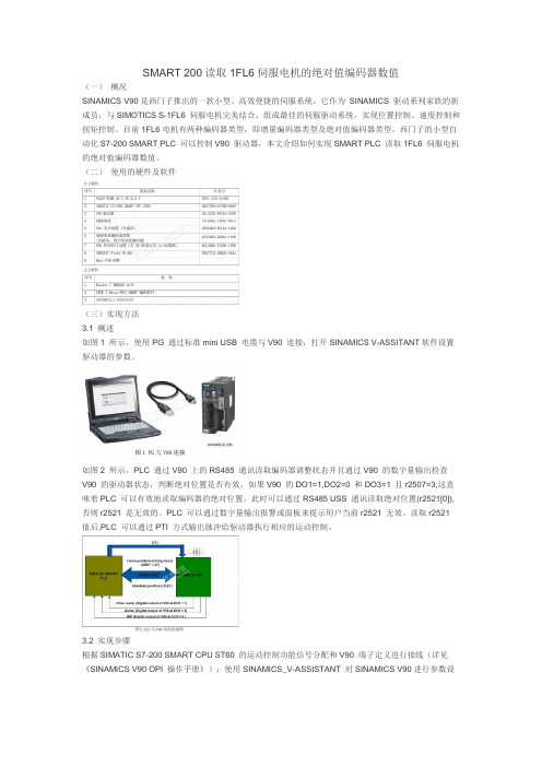
(二)使用的硬件及软件(三)实现方法3.1 概述如图1 所示,使用PG 通过标准mini USB 电缆与V90 连接,打开SINAMICS V-ASSITANT软件设置驱动器的参数。
如图2 所示,PLC 通过V90 上的RS485 通讯读取编码器调整状态并且通过V90 的数字量输出检查V90 的驱动器状态,判断绝对位置是否有效。
如果V90 的DO1=1,DO2=0 和DO3=1 且r2507=3,这意味着PLC 可以有效地读取编码器的绝对位置,此时可以通过RS485 USS 通讯读取绝对位置(r2521[0]),否则r2521 是无效的。
PLC 可以通过数字量输出报警或面板来提示用户当前r2521 无效。
读取r2521 值后,PLC 可以通过PTI 方式输出脉冲给驱动器执行相应的运动控制。
3.2 实现步骤根据SIMATIC S7-200 SMART CPU ST60 的运动控制功能信号分配和V90 端子定义进行接线(详见《SINAMICS V90 OPI 操作手册》);使用SINAMICS_V-ASSISTANT 对SINAMICS V90进行参数设置以及对电机的绝对值编码器进行调试;使用STEP 7-Micro/WIN SMART 编程软件对CPU ST60 进行组态和参数化,操作步骤如表1 所示。
V90伺服最常用的PTI调试
V90伺服最常用的PTI调试西门子公司为适应小型运动控制需求,推出一款小型高性能伺服SINAMICS V90。
SINAMICS V90 伺服驱动和SIMOTICS S-1FL6 伺服电机组成了性能优化,易于使用的伺服驱动系统,八种驱动类型,七种不同的电机轴高规格,功率范围从0.05kW到7.0kW以及单相和三相的供电系统使其可以广泛用于各行各业,如:定位,传送,收卷等设备中,同时该伺服系统可以与S7-1500T/S7-1500/S7-1200 进行完美配合实现丰富的运动控制功能。
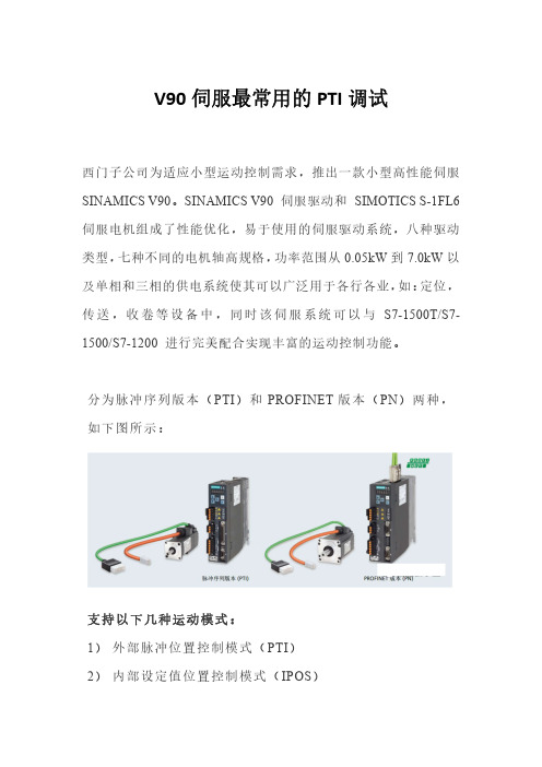
分为脉冲序列版本(PTI)和PROFINET版本(PN)两种,如下图所示:支持以下几种运动模式:1)外部脉冲位置控制模式(PTI)2)内部设定值位置控制模式(IPOS)3)速度模式(S)4)转矩模式(T)PTI是伺服应用中最基本使用最频繁的模式。
通过PLC发送高速脉冲来驱动伺服进行定位,对于伺服的调试较为简单,繁琐的是在PLC中编写高速脉冲输出程序。
首先应该对外部硬件连接,如下图所示。
接下来开始对参数进行调试,可以通过驱动器面板和V-ASSISTANT软件两种方式调试参数,但软件与驱动器连接后面板则无法使用。
此处简单介绍面板设置参数的方法,面板如下图所示。
启,方法如下图所示:所有参数调试完成后都需要进行断电保持设置,将修改的参数存储到ROM保持区,否则断电后恢复缺省值,方法如下图所示。
设置参数步骤如下图所示:在进入参数设置前需要选择正确的参数组号如P0A,0B,0C,0D等,也可选择P ALL组,进入后通过<移位键来修改参数编号,如下图所示。
注意:初次上电驱动器未与PLC相连时,常出现F7491 、F7492和A52902号错误。
原因为顺时针行程限制信号(CWL)和逆时针行程限制信号(CCWL)以及急停(EMGS)这三个信号为OFF。
默认必须为ON才可运行,如果实际使用时无需用到这三个功能,可通过把P29300的第1、2、6位设为1来强制为ON,如下图所示。
伺服电机内部结构及其工作原理分解
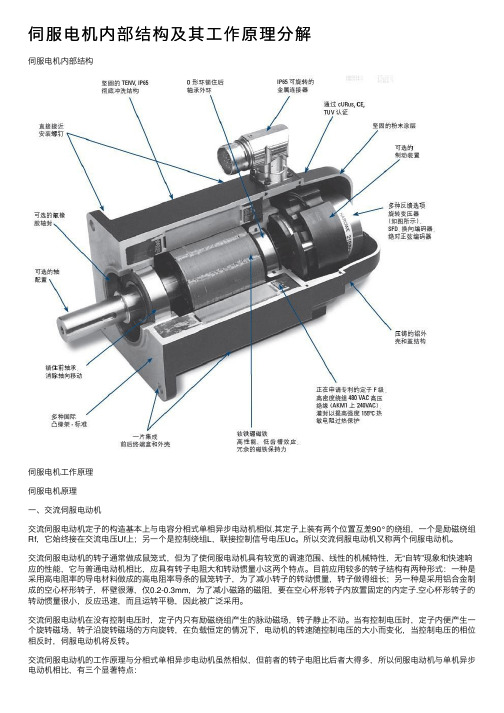
伺服电机内部结构及其⼯作原理分解伺服电机内部结构伺服电机⼯作原理伺服电机原理⼀、交流伺服电动机交流伺服电动机定⼦的构造基本上与电容分相式单相异步电动机相似.其定⼦上装有两个位置互差90°的绕组,⼀个是励磁绕组Rf,它始终接在交流电压Uf上;另⼀个是控制绕组L,联接控制信号电压Uc。
所以交流伺服电动机⼜称两个伺服电动机。
交流伺服电动机的转⼦通常做成⿏笼式,但为了使伺服电动机具有较宽的调速范围、线性的机械特性,⽆“⾃转”现象和快速响应的性能,它与普通电动机相⽐,应具有转⼦电阻⼤和转动惯量⼩这两个特点。
⽬前应⽤较多的转⼦结构有两种形式:⼀种是采⽤⾼电阻率的导电材料做成的⾼电阻率导条的⿏笼转⼦,为了减⼩转⼦的转动惯量,转⼦做得细长;另⼀种是采⽤铝合⾦制成的空⼼杯形转⼦,杯壁很薄,仅0.2-0.3mm,为了减⼩磁路的磁阻,要在空⼼杯形转⼦内放置固定的内定⼦.空⼼杯形转⼦的转动惯量很⼩,反应迅速,⽽且运转平稳,因此被⼴泛采⽤。
交流伺服电动机在没有控制电压时,定⼦内只有励磁绕组产⽣的脉动磁场,转⼦静⽌不动。
当有控制电压时,定⼦内便产⽣⼀个旋转磁场,转⼦沿旋转磁场的⽅向旋转,在负载恒定的情况下,电动机的转速随控制电压的⼤⼩⽽变化,当控制电压的相位相反时,伺服电动机将反转。
交流伺服电动机的⼯作原理与分相式单相异步电动机虽然相似,但前者的转⼦电阻⽐后者⼤得多,所以伺服电动机与单机异步电动机相⽐,有三个显著特点:1、起动转矩⼤由于转⼦电阻⼤,其转矩特性曲线如图3中曲线1所⽰,与普通异步电动机的转矩特性曲线2相⽐,有明显的区别。
它可使临界转差率S0>1,这样不仅使转矩特性(机械特性)更接近于线性,⽽且具有较⼤的起动转矩。
因此,当定⼦⼀有控制电压,转⼦⽴即转动,即具有起动快、灵敏度⾼的特点。
2、运⾏范围较⼴3、⽆⾃转现象正常运转的伺服电动机,只要失去控制电压,电机⽴即停⽌运转。
当伺服电动机失去控制电压后,它处于单相运⾏状态,由于转⼦电阻⼤,定⼦中两个相反⽅向旋转的旋转磁场与转⼦作⽤所产⽣的两个转矩特性(T1-S1、T2-S 2曲线)以及合成转矩特性(T-S曲线)交流伺服电动机的输出功率⼀般是0.1-100W。
Siemens SINAMICS V90 Servo Drive及SIMOTICS S-1FL6服动

Siemens SINAMICS V90 Servo driveSinamics V90 is complex servo drive system, which includes converter and SIMOTICS S-1FL6 servo motor. The series includes converter models with 8 frames sizes and 7 different motor shaft lengths.M ain features of v90 servo drives:8 different converters framesi z es;7 different motor shaft lenghts;It provides the solution for power range from 0.5 k W to 7 k W;The tool’s operations can perfectly be integrated with PTI,P RO FI NE T, U SS and also Modbus R T U;Ensures variable power supply.To find out stock ability and delivery time toyour region, please contact our manager.2ContentServo drive system overview ...............................03Servo drive system advantages ............................05SINAMICS V90 servo drive system in the automation environment ........................... 10SINAMICS V-ASSISTANT engineering tool .............10SINAMICS V90 technical dataand control features .............................................12System overview and connection diagrams .........15SIMOTICS S-1FL6 technical data and torque-speed characteristics ......................... 18Step-by-step selection ..........................................2A SINAMICS V90 and SIMOTICS S-1FL6ordering information ........................................... 3A SINAMICS V90 and SIMOTICS S-1FL6 dimensions and mounting clearances .................. 6AServo drive systemThe performance-optimized, user-friendly servo drive sys-tem comprises a SINAMICS V90 servo drive and a SIMOTICS S-1FL6 servomotor. Different frame sizes and motor shaft heights cover a wide range of applications for operation on single- and three-phase line supplies. There are eight servo drive frame sizes and seven motor shaft heights with power ratings ranging from 0.05 to 7.0 kilowatts, to realize a wide range of applications, with the focus on dynamic motion and processing – for example positioning, transporting and winding. In addition to operation in the TIA Portal V14 with the new SIMATIC S7-1500 T-CPU Advanced Controller, the servo drive system is also suitable for use with the SIMATIC S7-1500 Advanced Controller and the SIMATIC S7-1200 Basic Controller.3Pulse train version (PTI)PROFINET version (PN)SINAMICS V90 servo driveSINAMICS V90 can be integrated into a wide range of applications, either using the pulse train version (pulse/direction, analog, USS/Modbus RTU) or the product version with integrated PROFINET interface.The SINAMICS V90 pulse train version features internal positioning, positioning with pulse train as well as speed and torque control modes. SINAMICS V90 PROFINET version is equipped with an integrated PROFINET interface for link-ing the drive to an automation system via PROFIdrive pro-file. With integrated real-time auto tuning and automatic suppression of machine resonances, the system automati-cally optimizes itself to achieve high dynamic performanceand smooth operation.SIMOTICS S-1FL6 servomotorSIMOTICS S-1FL6 servomotors are naturally cooled, per- manent-magnet synchronous motors where the heat is dissipated through the motor surface. The motors can be simply and quickly installed using the full thread and quick-release connectors. They have a 300 percent over- load capability and can be combined with SINAMICS V90 servo drive to create a powerful servo system with a high degree of functionality.4** Position and speed control in combination with a motion function (TO axis) of SIMATIC S7-1500 T-CPU / S7-1500 / S7-1200*** For very low speed, high accuracy or high dynamic application TTL encoder is not recommendedPower, performance, typical applicationsCost effectiveMany integrated functions to reduce machine costs5Optimized servo performance Quick, smooth and precise positioning67Easy to useSimple tuning and quick commissioningReliable operation Robust in design and a safe choice89Integrated and innovativeSupport when selecting, commissioning and operating: powerful software tools1011Complete motion control solutionsfrom SiemensSINAMICS V90 System and SIMATIC – Siemens offers comprehensive solutions from a single source for general motion control applications. We can provide you with highly efficient systems, especially through the optimum interaction between SIMATIC control technology and SINAMICS drive technology with our “SINAMICS Application Examples.”Technical data – SINAMICS V90 servo drive12Control features – SINAMICS V90 servo drive* S INAMICS V90 PROFINET 200 V version not available in frame size A (FSA).The power range from 0.1 kW to 0.4 kW is covered with frame size B (FSB).** When SINAMICS V90 controls a motor equipped with brake, the tolerance of the 24 V DCpower supply must be –10% to +10% to comply with the voltage required by the brake.*** P ROFINET version requires a 24 V DC supply with max. 1.5 A (without a holding brake),or 3.5 A (with a holding brake). Refer to the operating instructions for detailed information.**** S INAMICS V90 PROFINET 400 V version is available in the 2nd half of 201613Connection diagram14Standard wiring for pulse train input (PTI) position control mode (for detailed information and connectiondiagrams for other control modes such as via PROFINET communication, please refer to the operating instructions). The diagram below provides a reference for selecting the drive type. When commissioning the selected servo drive system, establish the wiring connections according to the connection diagram and the instructions provided in the operating instructions.15System at glanceSINAMICS V90 servo drive system3AC 380 ... 480 V High Inertia (HI) for smooth operational performanceFrame size A Frame size B Frame size C Frame size D Control / setpoint / I/O cableSH 20SH 30SH 40 SH 50Power cableEncoder cableFrame size AA Frame size A Frame size B Frame size CSH 45SH 65SH 90Power cable Encoder cableControl / setpoint / I/OcablePTI PTI PN PN PN PNPTI PN PTI PTI PNPTI PTI PTI PNSINAMICS V90 servo driveHigh-quality metal connector Quick-release connector Shaft sleeve protectionSIMOTICS S-1FL6, Low Inertia motorHigh-quality bearings Oil seal with high wear resistanceIP65 as standard for all motorsCost-efficient, compact cablenot sufficient, disconnect DCP and R2, then connect DCP and R1 with 16SINAMICS PROFINET version • 2 RJ45 connectors for PROFINET communication with a PLC* Motor holding brake signal (only for SINAMICS 200 V version). The SINAMICS V90, 200 V version requires an external relay to connect the motor holding brake.System connection diagram* SIMOTICS S-1FL6 Low Inertia motors SH20, SH30, SH40 use outlet connection concept.**Brake cable connection shown here is for 400 V version only. The 200 V version requires an external relay to connect the motor brake cable.The relay has to be connected via the setpoint cable for the SINAMICS V90 pulse train version and via I/O cable for the SINAMICS V90 PROFINET version.*** I /O cable is necessary for the brake control of the SINAMICS V90 PROFINET 200 V version, and for applications requiring additional DI/DO in additionto PROFINET communication.**** For further information of PROFINET cable refer to /sc-static/catalogs/catalog/IK_PI_2015_en.pdf17SIMOTICS S-1FL6 Low Inertia for high dynamic performance1) Rated torque, rated power and maximum torque listed in the table above allow a production tolerance of 10%.2) It is not permissible to use the holding brake for an emergency stop.1819SIMOTICS S-1FL6 Low InertiaTorque-speed characteristic when connected to SINAMICS V90Supply voltage 220 V Supply voltage 198 VNotes:A: Continuous operating area B: Short-term operating areaSIMOTICS S-1FL6 High InertiaTorque-speed characteristic when connected to SINAMICS V90Supply voltage 400 V Supply voltage 380 VNotes:A: Continuous operating area B: Short-term operating area1) The rated torque, rated power and maximum torque listed in the table above allow for a production tolerance of 10%.2)For SIMOTICS S-1FL6 motors with brake, when the ambient temperature exceeds 30 ºC, the power should be derated by 10%. Power derating is not required for other motors.3) It is not permissible to use the holding brake for an emergency stop.4)Motor weight with incremental encoder.SIMOTICS S-1FL6 High Inertia for smooth operation1Select your motor: SIMOTICS S-1FL6at the required torque and speed3. Select encoder resolutionSelect your servo drive: SINAMICS V904SINAMICS V90 servo drive system Step-by-step selectionOrdering information:Recommended line-side components SINAMICS V90Recommended line filter 1)Recommended fuse/circuit breaker – IEC-compliant Recommended fuse/circuit breaker to – UL-compliant FuseCircuit breakerFuseCircuit breaker Line supply voltageArticle number 6SL3210-5F…Rated current Article numberRated current Article number Rated current, voltageArticle numberRated current, voltage Class Rated current, voltageArticle number200 ... 240 V 1ACB10-118 A6SL3203-0BB21-8VA06 A3NA3 801-2C2.8–4 A, 230/240 V3RV 2011-1EA106 AListed JDDZ2.8–4 A, 230/240 V3RV 2011-1EA10B10-26 A3NA3 801-2C2.8–4 A, 230/240 V 3RV 2011-1EA106 A Listed JDDZ 2.8–4 A, 230/240 V 3RV 2011-1EA10 B10-410 A3NA3 803-2C 5.5–8 A, 230/240 V3RV 2011-1HA10 10 AListed JDDZ 5.5–8 A, 230/240 V3RV 2011-1HA10 B10-816 A 3NA3 803-2C 9–12.5 A, 230/240 V 3RV 2011-1KA1020 A Listed JDDZ 9–12.5 A, 230/240 V 3RV 2011-1KA10200 ... 240 V 3ACB10-1 5 A6SL3203-0BE15-0VA06 A3NA3 801-2C2.8–4 A, 230/240 V3RV 2011-1EA106 AListed JDDZ2.8–4 A, 230/240 V3RV 2011-1EA10B10-26 A 3NA3 801-2C 2.8–4 A, 230/240 V 3RV 2011-1EA10 6 A Listed JDDZ 2.8–4 A, 230/240 V 3RV 2011-1EA10 B10-4 10 A3NA3 803-2C 2.8–4 A, 230/240 V 3RV 2011-1EA1010 A Listed JDDZ 2.8–4 A, 230/240 V 3RV 2011-1EA10 B10-8 16 A 3NA3 805-2C 5.5–8 A, 230/240 V 3RV 2011-1HA10 20 A Listed JDDZ 5.5–8 A, 230/240 V 3RV 2011-1HA10 B11-0 12 A6SL3203-0BE21-2VA016 A3NA3 805-2C 7–10 A, 230/240 V 3RV 2011-1JA1020 AListed JDDZ7–10 A, 230/240 V 3RV 2011-1JA10B11-5 25 A 3NA3 810-2C 10–16 A, 230/240 V 3RV 2011-4AA1025 A Listed JDDZ 10–16 A, 230/240 V 3RV 2011-4AA10B12-0 25 A 3NA3 810-2C 10–16 A, 230/240 V 3RV 2011-4AA1025 A Listed JDDZ 10–16 A, 230/240 V 3RV 2011-4AA10 380 ... 480 V 3ACE10-4 5 A 6SL3203-0BE15-0VA0 6 A 3NA3801-6 3.2 A, 690 V AC 3RV 2021-1DA1010 A Listed JDDZ3.2 A, 600 V AC 3RV 2021-1DA10E10-86 A3NA3801-6 4 A, 690 V AC 3RV 2021-1EA10 10 A Listed JDDZ 4 A, 690 V AC 3RV 2021-1EA10 E11-0 10 A 3NA3803-6 5 A, 690 V AC 3RV 2021-1FA10 10 A Listed JDDZ 5 A, 690 V AC 3RV 2021-1FA10 E11-5 12 A 6SL3203-0BE21-2VA0 10 A 3NA3803-6 10 A, 690 V AC 3RV 2021-1HA10 15 AListed JDDZ 10 A, 690 V AC 3RV 2021-1HA10E12-0 16 A 3NA3805-6 16 A, 690 V AC 3RV 2021-4AA1015 A Listed JDDZ 16 A, 690 V AC 3RV 2021-4AA10E13-5 20 A6SL3203-0BE22-0VA020 A3NA3807-6 20 A, 690 V AC3RV 2021-4BA1025 AListed JDDZ20 A, 690 V AC3RV 2021-4BA10E15-020 A 3NA3807-6 20 A, 690 V AC 3RV 2021-4BA10 25 A Listed JDDZ 20 A, 690 V AC 3RV 2021-4BA10 E17-0 25 A3NA3810-625 A, 690 V AC3RV 2021-4DA1025 AListed JDDZ25 A, 690 V AC3RV 2021-4DA10SIMOTICS S-1FL6 servomotorRated Power (kW)Rated torque (Nm)Rated speed (rpm)Shaft height (mm)Article numberHigh dynamic performance (Low Inertia)0.050.163000201FL6022-2AF21-110.100.3230001FL6024-2AF21-110.200.643000301FL6032-2AF21-110.40 1.2730001FL6034-2AF21-110.75 2.393000401FL6042-2AF21-111.00 3.1830001FL6044-2AF21-111.50 4.783000501FL6052-2AF21-012.00 6.3730001FL6054-2AF21-01Encoder typeIncremental encoder TTL 2500 ppr A Absolute encoder single-turn 21-bit*MSmooth opera-tion (High Inertia)0.40 1.273000451FL6042 -1AF61-010.75 2.3930001FL6044 -1AF61-010.75 3.582000651FL6061 -1AC61-011.00 4.7720001FL6062 -1AC61-011.507.1620001FL6064 -1AC61-011.758.420001FL6066 -1AC61-012.009.520001FL6067 -1AC61-012.5011.92000901FL6090 -1AC61-013.5016.720001FL6092 -1AC61-015.0023.920001FL6094 -1AC61-017.0033.420001FL6096 -1AC61-01Encoder typeIncremental encoder TTL 2500 pprA Absolute encoder 20-bit + 12-bit multi-turn LShaft typefeather key and holding brakeFeather key, without holding brake A Feather key, with holding brake**B Plain shaft, without holding brake G Plain shaft, with holding brake**H* available in the 2nd half of 2016** The SIMOTICS S-1FL6 Low Inertia motor requires an external relais to actuate the motor holding brake. See SINAMICS V90 operating instructions.1SINAMICS V90 servo driveRated power (kW)Line supply voltageFrame sizeArticle number0.10200 ... 240 V 1AC / 3ACFSA***6SL3210-5FB10-1U 00.206SL3210-5FB10-2U 00.40FSB 6SL3210-5FB10-4U 10.75FSC 6SL3210-5FB10-8U 01.00200 ... 240 V 3ACFSD6SL3210-5FB11-0U 11.506SL3210-5FB11-5U 02.006SL3210-5FB12-0U0.40380 ... 480 V 3AC FSAA 6SL3210-5FE10-4U 00.75FSA6SL3210-5FE10-8U 00.756SL3210-5FE11-0U 01.001.50FSB6SL3210-5FE11-5U 01.752.006SL3210-5FE12-0U02.503.50FSC6SL3210-5FE13-5U 05.006SL3210-5FE15-0U 07.006SL3210-5FE17-0U0SINAMICS V90 pulse train (PTI) version A SINAMICS V90 PROFINET (PN) version (V90 PROFINET version 400 V available in the 2nd half of 2016)F*** S INAMICS V90 PROFINET 200 V version is not available inframe size A (FSA). The power range from 0.1 kW to 0.4 kW is covered with frame size B (FSB).2SINAMICS V90 Servo systemMOTION-CONNECT 300 cables between SINAMICS V90 servo drive and SIMOTICS S-1FL6 servomotorPower cableEncoder cable Brake cable Article number Article numberArticle number 6FX3002-5CK01-16FX3002-220-16FX3002-5BK02-16FX3002-5CK31-106FX3002-210-106FX3002-5BL02-106FX3002-5CL01-106FX3002-210-106FX3002-5BL02-106FX3002-5CL11-1 0Length: 3 m A D A D A D Length: 5 m A F A F A F Length: 7 m 3) A H A H A H Length: 10 m B A B A B A Length: 20 m C AC A C AFor incremental encoder TTL 2500 ppr C T For absolute encoder single-turn 21-bit Absolute encoder 20-bit + 12-bit multi-turn D B3Cables between SINAMICS V90 servo drive and PLC Article number6SL3260-4NA00-1VB0Control/setpoint cable, 1 m cable with connector (MDR 50-pin connector, free pins to controller side) or6SL3260-4NA00-1VA5Control/setpoint cable 0.5 m cable with connectors on both sides and separate terminal block (MDR 50-pin connector, terminal block to controller side)I/O cable between SINAMICS V90 drive and controller Article number6SL3260-4MA00-1VB0I/O cable, 1 m cable with 20-pin MDR connector (free pins to controller side)PROFINET cable6GK1901-1BB10-2AA0RJ45 data plug-in connector, with 180° (straight) cable outlet6XV1840-2AH10Standard bus cable (4-core), sold by meter, not assembled6XV1871-5BH10Preassembled cable, 1 m, with two RJ45 plug-180Connectors ConnectorsPlug on Article number Packaging unit (pcs)50-pin MDR connector for setpoint cable drive side 6SL3260-2NA00-0VA030Encoder connectordrive side 6FX2003-0SB143020-pin MDR connector for I/O cable drive side 6SL3260-2MA00-0VA05Power connectormotor side 6FX2003-0LL1Incremental encoder TTL 2500 ppr connector motor side 6FX2003-0SL1Brake connectormotor side 6FX2003-0LL5Absolute encoder single-turn 21-bitAbsolute encoder 20-bit + 12-bit multi-turn connectormotor side6FX2003-0DB1For SIMOTICS S-1FL6 motors with shaft heights of 45, 50, 65, 90130For SIMOTICS S-1FL6 motors with shaft heights of 20, 30, and 4025Requirements for external braking resistor External braking resistor 2)Line supply voltage Frame sizeResis-tance (Ω)Max. power (kW) Rated power (W)Max. energy (kJ)200 ... 240 V 1AC/3ACFSA 150 1.09200.8FSB 100 1.6421 1.23FSC 50 3.2862 2.46FSD, 1 kW 50 3.2862 2.46FSD, 1.5 to 2 kW25 6.56123 4.92380 ... 480 V 3ACFSAA 533 1.230 2.4FSA 16041008FSB 709.122918.3FSC2723.71185189.6Replacement partsReplacement connector kits (contains control connectors, power connectors)for SINAMICS V90 400 V FSAA 6SL3200-0WT00-0AA0for SINAMICS V90 400 V FSA 6SL3200-0WT01-0AA0for SINAMICS V90 200 V FSA/FSB 6SL3200-0WT02-0AA0for SINAMICS V90 200 V FSC/FSD6SL3200-0WT03-0AA0Replacement fanfor SINAMICS V90 400 V FSB, 200 V FSD 6SL3200-0WF00-0AA0for SINAMICS V90 400 V FSC6SL3200-0WF01-0AA0SINAMICS V90 pulse train (PTI), USS/Modbus RTU version to SIMATIC controllerSIMATIC S7-1200 Basic controller CommunicationCPUArticle number Digital outputsRS 485communication for USS or Modbus RTUArticle numberCPU 1211C DC/DC/DC6ES7211-1-0XB0 4 DO with 100 kHzrest 30 kHz CM 1241 RS 422/485orCB 1241 RS 4856ES7241-1CH32-0XB0or6ES7241-1CH30-0XB0CPU 1212C DC/DC/DC6ES7212-1-0XB0CPU 1214C DC/DC/DC 6ES7214-1-0XB0CPU 1215C DC/DC/DC 6ES7215-1-0XB0CPU 1217C DC/DC/DC6ES7217-1-0XB04 DO with 1 MHz rest 100 kHz Signal boards Note:One SIMATIC S7-1200 CPU can control up to 4 SINAMICS V90 axes,while each axis requires 2 fast digital output for the pulse train interface. One SIMATIC S7-1200 CPU is only expandable with either a signal board or a communication board.For detailed and further information about SIMATIC controllers please refer to the SIMATIC S7-1200 brochure, catalog or web page: /simatic-s7-1200CPUArticle number Digital outputs SB 1222 DC 200 kHz 6ES7222-1BD30-0XB0 4 x 24 V DC 200 kHz SB 1222 DC 200 kHz 6ES7222-1AD30-0XB0 4 x 5 V DC 200 kHz SB 1223 DC/DC 200 kHz 6ES7223-3BD30-0XB0 2 x 24 V DC 200 kHz SB 1223 DC/DC 200 kHz6ES7223-3AD30-0XB02 x 5 V DC 200 kHz4SINAMICS V90 PROFINET version to SIMATIC controllerSIMATIC S7-1500/1500 T for advanced motion control SIMATIC S7-1200 for basic motion control Standard CPU Article number Failsafe CPU Article number CPUArticle number S7-15116ES7511-1AK01-0AB0S7-1511F6ES7511-1FK01-0AB01211C DC/DC/DC6ES7211-1-0XB0S7-15136ES7513-1AL01-0AB0S7-1513F 6ES7513-1FL01-0AB01212C DC/DC/DC 6ES7212-1 -0XB0S7-15156ES7515-2AM01-0AB0S7-1515F 6ES7515-2FM01-0AB01214C DC/DC/DC 6ES7214-1 -0XB0S7-15166ES7516-3AN01-0AB0S7-1516F 6ES7516-3FN01-0AB01215C DC/DC/DC 6ES7215-1 -0XB0S7-15176ES7517-3AP00-0AB0S7-1517F 6ES7517-3FP00-0AB01217C DC/DC/DC 6ES7217-1-0XB0S7-15186ES7518-4AP00-0AB0S7-1518F 6ES7518-4FP00-0AB0Technology CPU Article number Failsafe CPU Article number For further information about PROFINET cables refer to /sc-static/catalogs/ catalog/IK_PI_2015_en.pdfFor further information about SIMATIC controllers please refer to the SIMATIC S7 catalog or web page: /simaticS7-1511T 6ES7511-1TK01-0AB0––S7-1515T 6ES7515-2TM01-0AB0––S7-1517T6ES7517-3TP00-0AB0S7-1517TF6ES7517-3UP00-0AB0Note:Technology Objects: SINAMICS V90 as a PROFINET I/O device with PROFIdrive supports technology objects of S7-1200/S7-1500/S7-1500 T-CPU for speed and positioning control. Function blocks: SINAMICS V90 only supports SINA_SPEED (speed), SINA_POS (positioning) is NOT supported yet.4AccessoriesTraining case SINAMICS V90 LI, 200 V (PTI, USS/Modbus RTU version)6AG1067-2AA00-0AC0SINAMICS SD card for SINAMICS V90 in 400 V version6SL3054-4AG00-2AA0SIMATIC S7 controllerPLC Dimension drawings (mm)SIMOTICS S-1FL6 Low InertiaDimension drawings (mm) SIMOTICS S-1FL6 Low Inertia servomotorsNote:① Power connector, ② Incremental encoder connector, ③ Brake connectorConnectors should be ordered separately, for ordering information please refer to section “Options”in this document.Note:① Power connector, ② Incremental encoder connector, ③ Brake connectorConnectors should be ordered separately, for ordering information please refer to section “Options” in this document.Outline dimensions of ② incremental encoder connector ③ brake connector are the same.Shaft height 90 motor has M8 screws for eyebolts.SIMOTICS S-1FL6 High InertiaDimension drawings (mm) SIMOTICS S-1FL6 High Inertia servomotorswith absolute encoderNote:① Power connector, ② Absolute encoder connector, ③ Brake connectorConnectors should be ordered separately, for ordering information please refer to section “Options”in this document.Outline dimensions of ② absolute encoder connector ③ brake connector are the same.Shaft height 90 motor has M8 screws for eyebolts.9A********************+421 552 601 099********************+421 552 601 09SINAMICS G150 SINAMICS G180 S INAMI CS S120 S INAMI CS V 20ØSINAMICS P er f ect H armo ny other Siemens productsrange of Siemens Drives with the best prices and delivery terms.We supply:Eltra Trade s.r.o. supplies full STAY UPDATEDBest pricesThe fastest supply Best level technicalsupportCustomers in over 100 countries ********************+421 552 601 09 ********************+421 552 601 099To find out stock ability and delivery time to your region, please contact our manager.info @eltra 。
S7-200_SMART 系统手册

SIMATICS7-200 SMART2013 年 10 月版 S7-200 SMART 系统手册更新信息产品信息S7-200 SMART 文档更新概述尽管我们力求确保产品文档条理清楚与准确无误,但《S7-200 SMART 系统手册》中的一些页面仍包含不完整、不正确或误导性的信息。
使用 AXISx_ABSPOS 子例程从 SINAMICS V90 伺服驱动器读取绝对位置以下几部分提供了如何在项目中使用 AXISx_ABSPOS 子例程从 SINAMICS V90 伺服驱动器读取绝对位置的更多信息:●AXISx_ABSPOS 子例程 (页 1)●用法示例 (页 3)●互连详细信息 (页 4)●影响互操作性的调试问题 (页 4)AXISx_ABSPOS 子例程当您在“从驱动器读取绝对位置”(Read Absolute Position from Drive) 对话框中选中“启用”(Enabled) 复选框并单击“生成”(Generate) 按钮以构建向导生成的子例程时,STEP 7-Micro/WIN SMART 的运动控制向导将创建 AXISx_ABSPOS 子例程。
© Siemens AG 2013. 保留所有权利AXISx_ABSPOS 子例程的接口和参数说明如下所示:输入/输出数据类型2013 年 10 月版 S7-200 SMART 系统手册更新信息AXISx_ABSPOS 和 AXISx_LDPOS 子例程用法示例在 START 参数开启的情况下执行 AXISx_ABSPOS 子例程时,仅当成功完成该子例程后(Done 参数 = ON 且 Error 参数=“无错误”),绝对位置才有效。
在 START 输入关闭的情况下执行子例程时,由于 Error 和 D_Pos 参数会恢复为默认值,因此在完成子例程后,您必须将指令包含在您的程序中,以捕获有效的绝对位置值。
2013 年 10 月版 S7-200 SMART 系统手册更新信息互连数字量 I/O请参见SINAMICS V90/SIMOTICS S-1FL6 操作说明文档中的“PLC 连接示例”部分,以查找有关 S7-200 SMART CPU 和 V90 伺服驱动器之间的数字量控制信号连接的建议接线图。
- 1、下载文档前请自行甄别文档内容的完整性,平台不提供额外的编辑、内容补充、找答案等附加服务。
- 2、"仅部分预览"的文档,不可在线预览部分如存在完整性等问题,可反馈申请退款(可完整预览的文档不适用该条件!)。
- 3、如文档侵犯您的权益,请联系客服反馈,我们会尽快为您处理(人工客服工作时间:9:00-18:30)。
affected by the procedure. 2. Disconnect the machine from the supply.
- Switch off the machine. - Wait until the discharge time specified on the warning
labels has elapsed. - Check that it really is in a no-voltage condition, from
phase conductor to phase conductor and phase conductor to protective conductor. - Check whether the existing auxiliary supply circuits are de-energized. - Ensure that the motors cannot move. 3. Identify all other hazardous energy sources, e.g. compressed air, hydraulic systems, water. 4. Isolate or neutralize all hazardous energy sources by closing switches, grounding or short-circuiting or closing valves, for example. 5. Secure the energy sources against switching on again. 6. Ensure that the machine is completely interlocked. After you have completed the work, restore the operational readiness in the inverse sequence.
control cabinet (or protect the device by another equivalent measure) in such a way that contact with fire is prevented. • Ensure that smoke can only escape via controlled and monitored paths.
Death or serious injury can result when live parts are touched.
• Only work on electrical devices when you are qualified for this job.
• Always observe the country-specific safety rules. Generally, six steps apply when establishing safety: 1. Prepare for shutdown and notify all those who will be
• Ground the device in compliance with the applicable regulations.
© Siemens AG 2013-2015
WARNING
Danger to life due to electric shock when opening plug connections in operation When opening plug connections in operation, arcs can result in severe injury or death. • Only open plug connections when the equipment is in a
For missing or incorrectly implemented protective conductor connection for devices with protection class I, high voltages can be present at open, exposed parts, which when touched, can result in death or severe injury.
no-voltage state, unless it has been explicitly stated that they can be opened in operation.
WARNING
Danger to life due to fire spreading if housing is inadequate Fire and smoke development can cause severe personal injury or material damage. • Install devices without a protective housing in a metal
WARNING
Danger to life through a hazardous voltage when connecting an unsuitable power supply
Death or serious injury can result when live parts are touched in the event of a fault. • Only use power supplies that provide SELV (Safety Extra
Low Voltage) or PELV-(Protective Extra Low Voltage) output voltages for all connections and terminals of the electronics modules.
WARNING
Danger to life when live parts are touched on damaged motors/devices Improper handling of motors/devices can cause damage. For damaged motors/devices, hazardous voltages can be present at the enclosure or exposed components; if touched, this can result in death or severe injury. • Ensure compliance with the limit values specified in the
WARNING
Danger to life through unexpected movement of machines when using mobile wireless devices or mobile phones Using mobile wireless devices or mobile phones with a transmitter power > 1 W closer than approx. 2 m to the components may cause the devices to malfunction, influence the functional safety of machines therefore putting people at risk or causing material damage. • Switch the wireless devices or mobile phones off in the
insulation is not overloaded.
WARNING
Danger to life due to fire if overheating occurs because of insufficient ventilation clearances Inadequate ventilation clearances can cause overheating of components with subsequent fire and smoke. This can cause severe injury or even death. This can also result in increased downtime and reduced service lives for devices/systems. • Ensure compliance with the specified minimum clearance
immediate vicinity of the components.
Wቤተ መጻሕፍቲ ባይዱRNING
Danger to life due to the motor catching fire in the event of insulation overload There is higher stress on the motor insulation through a ground fault in an IT system. If the insulation fails, it is possible that death or severe injury can occur as a result of smoke and fire. • Use a monitoring device that signals an insulation fault. • Correct the fault as quickly as possible so the motor
