3-146499-5中文资料
1-1469491-2中文资料

1-1469491-2 Product DetailsHome | Customer Support | Suppliers | Site Map | Privacy Policy | Browser Support© 2008 Tyco Electronics Corporation All Rights Reserved SearchProducts Documentation Resources My Account Customer SupportHome > Products > By Type > Two-Piece, High-Speed Connectors > Product Feature Selector > Product Details1-1469491-2Active MULTIGIG RT ProductAlways EU RoHS/ELV Compliant (Statement of Compliance)Product Highlights:?Pin, External Thread?Guidance Series?VITA 41/VITA 46 Configuration?Used With 9mm Guide ModuleView all Features | Find SimilarProductsCheck Pricing &AvailabilitySearch for ToolingProduct FeatureSelectorContact Us AboutThis ProductQuick LinksDocumentation & Additional InformationProduct Drawings:?KEYED GUIDE PIN, DIE CAST BACKPLANE CONNECTOR, MULTI...(PDF, English)Catalog Pages/Data Sheets:?Power Connectors & Interconnection Systems Catalog -...(PDF, English)?MULTIGIG RT Connector Products for VITA 46 (VPX) Sta...(PDF, English)Product Specifications:?None AvailableApplication Specifications:?None AvailableInstruction Sheets:?None AvailableCAD Files:?None AvailableList all Documents Additional Information:?Product Line InformationRelated Products:?ToolingProduct Features (Please use the Product Drawing for all design activity)Product Type Features:?Product Type = Pin, External Thread ?Finish = Silver?Comment = KeyedBody Related Features:?Series = Guidance?Used With = 9mm Guide Module?Pin Material = Zinc Alloy Industry Standards:?RoHS/ELV Compliance = RoHS compliant, ELVcompliant?Lead Free Solder Processes = Not relevant forlead free process?VITA 41/VITA 46 Configuration = Yes?RoHS/ELV Compliance History = Always wasRoHS compliantOther:?Brand = AMPProvide Website Feedback | Contact Customer Support。
钢号对照表
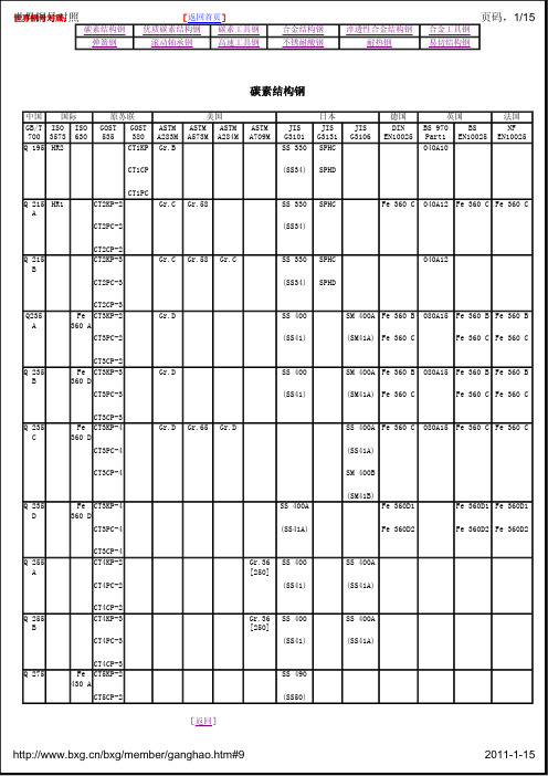
080A86 英国
BS 080A15,
法国 前苏联 国际
NF ГОСТ ISO 15Г
2011-1-15
世界钢量号钢组对照
20Mn
25Mn 30Mn
35Mn 40Mn
45Mn
50Mn
60Mn 65Mn
70Mn
S28C S30C
S35C S40C
S45C
S53C
40Mn4(1.5038) [返回]
1019 1019 1019 1021, 1021, 1021,
世世界界钢钢号号对照对:照
碳素结构钢 弹簧钢
[返回首页]
优质碳素结构钢 碳素工具钢
滚动轴承钢
高速工具钢
合金结构钢 不锈耐酸钢
淬透性合金结构钢 耐热钢
页码,1/15
合金工具钢
易切结构钢
碳素结构钢
中国 国际 GB/T ISO ISO 700 3573 630 Q 195 HR2
原苏联 GOST GOST 535 380
20F
20
S20C,
S20CK S22C
25
S25C
S28C
30
S30C
C22(1.0402), CK22(1.1151)
S33C
35
S35C
C35(1.0501),
CK35(1.1181),
/bxg/member/ganghao.Chmt3m5(#1.91180)
GB,YB 05F 08F 08
日本 JIS
S09CK(S9CK)
10F
10
S10C
德国 DIN(W-Nr.)
C10(1.0301), CK10(1.1121) CK10(1.1121)
ACI 349

ACI 349-06 supersedes ACI 349/349R-01, was adopted November 7, 2006, and was published September 2007.Copyright © 2007, American Concrete Institute.All rights reserved including rights of reproduction and use in any form or by any means, including the making of copies by any photo process, or by electronic or mechanical device, printed, written, or oral, or recording for sound or visual reproduction or for use in any knowledge or retrieval system or device, unless permission in writing is obtained from the copyright proprietors.349-1ACI Committee Reports, Guides, Standard Practices, and Commentaries are intended for guidance in planning,designing, executing, and inspecting construction. This document is intended for the use of individuals who are competent to evaluate the significance and limitations of its content and recommendations and who will accept responsibility for the application of the material it contains.The American Concrete Institute disclaims any and all responsibility for the stated principles. The Institute shall not be liable for any loss or damage arising therefrom.Reference to this document shall not be made in contract documents. If items found in this document are desired by the Architect/Engineer to be a part of the contract documents, they shall be restated in mandatory language for incorporation by the Architect/Engineer.Code Requirements for Nuclear Safety-Related Concrete Structures (ACI 349-06) and CommentaryAn ACI StandardReported by ACI Committee 349ACI 349-06This standard covers the proper design and construction of concrete structures that form part of a nuclear power plant and that have nuclear safety-related functions, but does not cover concrete reactor vessels and concrete containment structures (as defined by Joint ACI-ASME Committee 359).The structures covered by the Code include concrete structures inside and outside the containment system.This Code may be referenced and applied subject to agreement between the owner and the Regulatory Authority.All notation sections have been removed from the beginning of each chapter and consolidated into one list in Chapter 2.The format of this Code is based on the “Building Code Requirements for Structural Concrete (ACI 318-05)” and incorporates recent revisions of that standard.The commentary, which is presented after the Code, discusses some of the considerations of ACI Committee 349 in developing “Code Requirements for Nuclear Safety-Related Concrete Structures (ACI 349-06).” This information is provided in the commentary because the Code is written as a legal document and therefore cannot present background details or suggestions for carrying out its requirements.Keywords : admixtures; aggregates; anchorage (structural); authority having jurisdiction (AHJ); beam-column frame; beams (supports); building codes; cements; cold weather construction; columns (supports); combined stress; composite construction (concrete and steel); composite construction (concrete to concrete); compressive strength; concrete construction;concretes; concrete cover; concrete slabs; construction joints; continuity (structural); cracking (fracturing); creep properties; curing; deep beams;deflection; drawings (drafting); earthquake-resistant structures; edge beams; embedded service ducts; flexural strength; floors; folded plates;footings; formwork (construction); frames; hot weather construction;inspection; joists; load tests (structural); loads (forces); mixing; mixture proportioning; modulus of elasticity; moments; nuclear power plants;nuclear reactor containments; nuclear reactor safety; nuclear reactors; pipe columns; pipes (tubes); placing; precast concrete; prestressed concrete;prestressing steels; quality control; reinforced concrete; reinforcing steels;roofs; safety; serviceability; shear strength; shearwalls; shells (structural forms); spans; specifications; splicing; strength; strength analysis; structural analysis; structural design; T-beams; temperature; torsion; walls; water;welded wire reinforcement.CONTENTSCODEChapter 1—General requirements, p. 349-61.1—Scope1.2—Drawings and specifications 1.3—Inspection1.4—Approval of special systems of design or construction 1.5—Quality assurance programHansraj G. Ashar Partha S. Ghosal Jagadish R. Joshi Bozidar Stojadinovic Ranjit L. BandyopadhyayHerman L. Graves III Richard E. Klingner Barendra K. Talukdar Peter J. CarratoOrhan Gurbuz Nam-Ho Lee Donald T. Ward Ronald A. Cook James A. Hammell Dan J. Naus Andrew S. Whittaker Rolf Eligehausen Gunnar A. Harstead Dragos A. Nuta Albert Y . C. Wong Werner Fuchs Christopher Heinz Richard S. OrrCharles A. ZalesiakBranko GalunicCharles J. HookhamRonald J. JanowiakChair349-2ACI STANDARDChapter 2—Notation and definitions, p. 349-72.1—Code notation2.2—DefinitionsChapter 3—Materials, p. 349-173.1—Tests of materials3.2—Cements3.3—Aggregates3.4—Water3.5—Steel reinforcement3.6—Admixtures3.7—Storage and identification of materials3.8—Referenced standardsChapter 4—Durability requirements, p. 349-214.1—Water-cementitious material ratio4.2—Freezing and thawing exposures4.3—Sulfate exposures4.4—Corrosion protection of reinforcementChapter 5—Concrete quality, mixing, and placing, p. 349-225.1—General5.2—Selection of concrete proportions5.3—Proportioning on the basis of field experience or trialmixtures, or both5.4—Proportioning without field experience or trialmixtures5.5—Average compressive strength reduction5.6—Evaluation and acceptance of concrete5.7—Preparation of equipment and place of deposit5.8—Mixing5.9—Conveying5.10—Depositing5.11—Curing5.12—Cold weather requirements5.13—Hot weather requirementsChapter 6—Formwork, embedded pipes, and construction joints, p. 349-266.1—Design of formwork6.2—Removal of forms, shores, and reshoring6.3—Conduits and pipes embedded in concrete6.4—Construction jointsChapter 7—Details of reinforcement, p. 349-287.1—Standard hooks7.2—Minimum bend diameters7.3—Bending7.4—Surface conditions of reinforcement7.5—Placing reinforcement7.6—Spacing limits for reinforcement7.7—Concrete protection for reinforcement7.8—Special reinforcement details for columns7.9—Connections7.10—Lateral reinforcement for compression members 7.11—Lateral reinforcement for flexural members7.12—Minimum reinforcement7.13—Requirements for structural integrity Chapter 8—Analysis and design—general considerations, p. 349-328.1—Design methods8.2—Loading8.3—Methods of analysis8.4—Redistribution of negative moments in continuousflexural members8.5—Modulus of elasticity8.6—Stiffness8.7—Span length8.8—Columns8.9—Arrangement of live load8.10—T-beam construction8.11—Joist construction8.12—Separate floor finishChapter 9—Strength and serviceability requirements, p. 349-349.1—General9.2—Required strength9.3—Design strength9.4—Design strength for reinforcement9.5—Control of deflectionsChapter 10—Flexure and axial loads, p. 349-37 10.1—Scope10.2—Design assumptions10.3—General principles and requirements10.4—D istance between lateral supports of flexuralmembers10.5—Minimum reinforcement of flexural members 10.6—Distribution of flexural reinforcement in beams andone-way slabs10.7—Deep beams10.8—Design dimensions for compression members 10.9—Limits for reinforcement of compression members 10.10—Slenderness effects in compression members 10.11—Magnified moments—general10.12—Magnified moments—nonsway frames10.13—Magnified moments—sway frames10.14—Axially loaded members supporting slab system 10.15—Transmission of column loads through floorsystem10.16—Composite compression members10.17—Bearing strengthChapter 11—Shear and torsion, p. 349-4211.1—Shear strength11.2—Lightweight concrete11.3—Shear strength provided by concrete for non-prestressed members11.4—Shear strength provided by concrete for prestressedmembers11.5—Shear strength provided by shear reinforcement 11.6—Design for torsion11.7—Shear-friction11.8—Deep beams11.9—Special provisions for brackets and corbels11.10—Special provisions for wallsCODE REQUIREMENTS FOR NUCLEAR SAFETY-RELATED CONCRETE STRUCTURES349-311.11—Transfer of moments to columns11.12—Special provisions for slabs and footings Chapter 12—Development and splices of reinforcement, p. 349-5112.1—Development of reinforcement—general12.2—Development of deformed bars and deformed wirein tension12.3—Development of deformed bars and deformed wirein compression12.4—Development of bundled bars12.5—Development of standard hooks in tension12.6—Mechanical anchorage12.7—Development of welded deformed wire reinforce-ment in tension12.8—D evelopment of welded plain wire reinforcementin tension12.9—Development of prestressing strand12.10—Development of flexural reinforcement—general 12.11—Development of positive moment reinforcement 12.12—Development of negative moment reinforcement 12.13—Development of web reinforcement12.14—Splices of reinforcement—general12.15—Splices of deformed bars and deformed wire intension12.16—Splices of deformed bars in compression12.17—Special splice requirements for columns12.18—Splices of welded deformed wire reinforcement intension12.19—Splices of welded plain wire reinforcement intensionChapter 13—Two-way slab systems, p. 349-56 13.1—Scope13.2—Definitions13.3—Slab reinforcement13.4—Openings in slab systems13.5—Design procedures13.6—Direct design method13.7—Equivalent frame methodChapter 14—Walls, p. 349-6214.1—Scope14.2—General14.3—Minimum reinforcement14.4—Walls designed as compression members14.5—Empirical design method14.6—Nonbearing walls14.7—Walls as grade beams14.8—Alternative design of slender wallsChapter 15—Footings, p. 349-6315.1—Scope15.2—Loads and reactions15.3—Footings supporting circular or regular polygon-shaped columns or pedestals15.4—Moment in footings15.5—Shear in footings15.6—Development of reinforcement in footings15.7—Minimum footing depth15.8—Transfer of force at base of column, wall, orreinforced pedestal15.9—Sloped or stepped footings15.10—Combined footings and matsChapter 16—Precast concrete, p. 349-6516.1—Scope16.2—General16.3—Distribution of forces among members16.4—Member design16.5—Structural integrity16.6—Connection and bearing design16.7—Items embedded after concrete placement16.8—Marking and identification16.9—Handling16.10—Strength evaluation of precast constructionChapter 17—Composite concrete flexural members, p. 349-6717.1—Scope17.2—General17.3—Shoring17.4—Vertical shear strength17.5—Horizontal shear strength17.6—Ties for horizontal shearChapter 18—Prestressed concrete, p. 349-6818.1—Scope18.2—General18.3—Design assumptions18.4—Serviceability requirements—flexural members 18.5—Permissible stresses in prestressing steel18.6—Loss of prestress18.7—Flexural strength18.8—Limits for reinforcement of flexural members 18.9—Minimum bonded reinforcement18.10—Statically indeterminate structures18.11—Compression members—combined flexure andaxial loads18.12—Slab systems18.13—Post-tensioned tendon anchorage zones18.14—Intentionally left blank18.15—Intentionally left blank18.16—Corrosion protection for unbonded tendons18.17—Post-tensioning ducts18.18—Grout for bonded tendons18.19—Protection for prestressing steel18.20—Application and measurement of prestressing force 18.21—Post-tensioning anchorages and couplers18.22—External post-tensioningChapter 19—Shells, p. 349-7319.1—Scope19.2—General19.3—Design strength of materials19.4—Section design and reinforcement requirements 19.5—Construction349-4ACI STANDARDChapter 20—Strength evaluation of existing structures, p. 349-7420.1—Strength evaluation—general20.2—Analytical investigations—general20.3—Load tests—general20.4—Load test procedure20.5—Loading criteria20.6—Acceptance criteria20.7—SafetyChapter 21—Provisions for seismic design,p. 349-7521.1—Definitions21.2—General requirements21.3—Flexural members of moment frames21.4—Moment frame members subjected to bending andaxial load21.5—Joints of moment frames21.6—Intentionally left blank21.7—Reinforced concrete structural walls and couplingbeams21.8—Intentionally left blank21.9—Structural diaphragms and trusses21.10—FoundationsAPPENDIXESAppendix A—Strut-and-tie models, p. 349-82A.1—DefinitionsA.2—Strut-and-tie model design procedureA.3—Strength of strutsA.4—Strength of tiesA.5—Strength of nodal zonesAppendix B—Intentionally left blank, p. 349-84Appendix C—Alternative load and strength- reduction factors, p. 349-84C.1—GeneralC.2—Required strengthC.3—Design strengthAppendix D—Anchoring to concrete, p. 349-85 D.1—DefinitionsD.2—ScopeD.3—General requirementsD.4—General requirements for strength of anchorsD.5—Design requirements for tensile loadingD.6—Design requirements for shear loadingD.7—Interaction of tensile and shear forcesD.8—Required edge distances, spacings, and thicknessesto preclude splitting failureD.9—Installation of anchorsD.10—Structural plates, shapes, and specialty inserts D.11—Shear strength of embedded plates and shear lugs D.12—Grouted embedmentsAppendix E—Thermal considerations, p. 349-92 E.1—ScopeE.2—DefinitionsE.3—General design requirementsE.4—Concrete temperaturesAppendix F—Special provisions for impulsive and impactive effects, p. 349-93F.1—ScopeF.2—Dynamic strength increaseF.3—DeformationF.4—Requirements to assure ductilityF.5—Shear strengthF.6—Impulsive effectsF.7—Impactive effectsF.8—Impactive and impulsive loadsAppendix G—SI metric equivalents of U.S. Customary Units, p. 349-96COMMENTARYIntroduction, p. 349-101Chapter R1—General requirements, p. 349-101R1.1—ScopeR1.2—Drawings and specificationsR1.3—InspectionR1.4—Approval of special systems of design or construction R1.5—Quality assurance programChapter R2—Notation and definitions, p. 349-102 R2.1—Commentary notationR2.2—DefinitionsChapter R3—Materials, p. 349-102R3.1—Tests of materialsR3.2—CementsR3.3—AggregatesR3.4—WaterR3.5—Steel reinforcementR3.6—AdmixturesR3.7—Storage and identification of materialsChapter R4—Durability requirements, p. 349-104R4.2—Freezing and thawing exposuresR4.3—Sulfate exposuresR4.4—Corrosion protection of reinforcementChapter R5—Concrete quality, mixing, and placing, p. 349-105R5.1—GeneralR5.3—Proportioning on the basis of field experience, or trial mixtures, or bothR5.4—Proportioning without field experience or trial mixturesR5.6—Evaluation and acceptance of concreteR5.7—Preparation of equipment and place of depositR5.9—ConveyingR5.10—DepositingR5.11—CuringR5.12—Cold weather requirementsR5.13—Hot weather requirementsCODE REQUIREMENTS FOR NUCLEAR SAFETY-RELATED CONCRETE STRUCTURES349-5Chapter R6—Formwork, embedded pipes, and construction joints, p. 349-108R6.1—Design of formworkR6.2—Removal of forms, shores, and reshoringR6.3—Conduits and pipes embedded in concreteR6.4—Construction jointsChapter R7—Details of reinforcement, p. 349-108 R7.4—Surface conditions of reinforcementR7.12—Minimum reinforcementR7.13—Requirements for structural integrityChapter R8—Analysis and design—general considerations, p. 349-109R8.2—LoadingR8.3—Methods of analysisR8.5—Modulus of elasticityR8.11—Joist constructionChapter R9—Strength and serviceability requirements, p. 349-109R9.1—GeneralR9.2—Required strengthR9.3—Design strengthR9.4—Design strength for reinforcementR9.5—Control of deflectionsChapter R10—Flexure and axial loads, p. 349-113 R10.6—D istribution of flexural reinforcement in beams and one-way slabsChapter R11—Shear and torsion, p. 349-113R11.12—Special provisions for slabs and footingsChapter R12—Development and splices of reinforcement, p. 349-113R12.6—Mechanical anchorageR12.14—Splices of reinforcement—generalR12.15—Splices of deformed bars and deformed wire in tensionChapter R13—Two-way slab systems, p. 349-114Chapter R14—Walls, p. 349-114R14.3—Minimum reinforcementChapter R15—Footings, p. 349-114Chapter R16—Precast concrete, p. 349-114Chapter R17—Composite concrete flexural members, p. 349-114Chapter R18—Prestressed concrete, p. 349-114Chapter R19—Shells, p. 349-114R19.1—ScopeR19.2—GeneralR19.4—Section design and reinforcement requirements Chapter 20—Strength evaluation of existing structures, p. 349-115R20.1—Strength evaluation—generalR20.2—Analytical investigations—generalR20.3—Load tests—generalR20.4—Load test procedureR20.5—Loading criteriaR20.6—Acceptance criteriaChapter R21—Provisions for seismic design,p. 349-116R21.1—DefinitionsR21.2—General requirementsR21.3—Flexural members of moment framesR21.4—Moment frame members subjected to bending and axial loadR21.5—Joints of moment framesR21.6—Intentionally left blankR21.7—Reinforced concrete structural walls and coupling beamsR21.8—Intentionally left blankR21.9—Structural diaphragms and trussesR21.10—FoundationsAPPENDIXESAppendix RA—Strut-and-tie models, p. 349-127Appendix RB—Intentionally left blank, p. 349-127Appendix RC—Alternative load and design strength-reduction factors, p. 349-127RC.1—GeneralRC.2—Required strengthRC.3—Design strengthAppendix RD—Anchoring to concrete, p. 349-128 RD.1—DefinitionsRD.2—ScopeRD.3—General requirementsRD.4—General requirements for strength of anchors RD.5—Design requirements for tensile loadingRD.6—Design requirements for shear loadingRD.7—Interaction of tensile and shear forcesRD.8—Required edge distances, spacings, and thicknesses to preclude splitting failureRD.9—Installation of anchorsRD.10—Structural plates, shapes, and specialty inserts RD.11—Shear strength of embedded plates and shear lugs Appendix RE—Thermal considerations, p. 349-141 RE.1—ScopeRE.2—DefinitionsRE.3—General design requirementsRE.4—Concrete temperaturesAppendix RF—Special provisions for impulsive and impactive effects, p. 349-144RF.1—ScopeRF.2—Dynamic strength increaseRF.3—Deformation349-6ACI STANDARDRF.4—Requirements to assure ductilityRF.5—Shear strengthRF.6—Impulsive effectsRF.7—Impactive effectsRF.8—Impactive and impulsive loadsSummary of changes for 349-06 Code, p. 349-150 CODECHAPTER 1—GENERAL REQUIREMENTS1.1—Scope1.1.1 This Code provides minimum requirements for design and construction of nuclear safety-related concrete structures and structural members for nuclear power generating stations. Safety-related structures and structural members subject to this standard are those concrete structures that support, house, or protect nuclear safety class systems or component parts of nuclear safety class systems. Specifically excluded from this Code are those structures covered by “Code for Concrete Reactor Vessels and Containments,” ASME Boiler and Pressure Vessel Code Section III, Division 2, and pertinent General Requirements (ACI 359).This Code includes design and loading conditions that are unique to nuclear facilities, including shear design under biaxial tension conditions, consideration of thermal and seismic effects, and impact and impulsive loads.For structural concrete, f c′ shall not be less than 2500 psi, unless otherwise specified.1.1.2 This Code shall govern in all matters pertaining to design and construction of reinforced concrete structures, as defined in 1.1.1, except wherever this Code is in conflict with the specific provisions of the authority having jurisdiction (AHJ).1.1.3 This Code shall govern in all matters pertaining to design, construction, and material properties wherever this Code is in conflict with requirements contained in other standards referenced in this Code.1.1.4 For special structures, such as arches, tanks, reservoirs, bins and silos, blast-resistant structures, and chimneys, provisions of this Code shall govern where applicable.1.1.5 Intentionally left blank.1.1.6 Intentionally left blank.1.1.7Concrete on steel form deck1.1.7.1 D esign and construction of structural concrete slabs cast on stay-in-place, noncomposite steel form deck are governed by this Code.1.1.7.2 This Code does not govern the design of structural concrete slabs cast on stay-in-place, composite steel form deck. Concrete used in the construction of such slabs shall be governed by Chapters 1 through 7 of this Code, where applicable.1.1.8Special provisions for earthquake resistance—Provisions of Chapter 21 shall be satisfied. See 21.2.1.1.2—Drawings and specifications1.2.1 Copies of design drawings, typical details, and specifications for all structural concrete construction shall bear the seal of a licensed engineer. These drawings (including supplementary drawings to generate the as-built condition), typical details, and specifications shall be retained by the owner, or his designee, as a permanent record for the life of the structure. As a minimum, these drawings, details, and specifications together shall show:(a)Name and date of issue of Code and supplement towhich design conforms;(b)Live load and other loads used in design;(c)Specified compressive strength of concrete at statedages or stages of construction for which each part of structure is designed;(d)Specified strength or grade of reinforcement;(e)Size and location of all structural members, reinforcement,and anchors;(f)Provision for dimensional changes resulting from creep,shrinkage, and temperature;(g)Magnitude and location of prestressing forces;(h)Anchorage length of reinforcement and location andlength of lap splices;(i)Type and location of mechanical and welded splices ofreinforcement;(j)Details and location of all contraction or isolation joints; (k)Minimum concrete compressive strength at time of post tensioning;(l)Stressing sequence for post-tensioning tendons; (m)Statement if slab-on-ground is designed as a structural diaphragm, see 21.10.3.4.1.2.2 Calculations pertinent to design and the basis of design (including the results of model analysis, if any) shall be retained by the owner or his designee, as a permanent record for the life of the structure. Accompanying these calculations shall be a statement of the applicable design and analysis methods. When computer programs are used, design assumptions and identified input and output data may be retained instead of calculations. Model analysis shall be permitted to supplement calculations.1.3—Inspection1.3.1 The owner is responsible for the inspection of concrete construction throughout all work stages. The owner shall require compliance with design drawings and specifications. The owner shall also keep records required for quality assurance and traceability of construction, fabrication, material procurement, manufacture, or installation.1.3.2 The owner shall be responsible for designating the records to be maintained and the duration of retention. Records pertinent to plant modifications or revisions, in-service inspections, and durability and performance of structures shall be maintained for the life of the plant. The owner shall be responsible for continued maintenance of the records. The records shall be maintained at the power plant site, or at other locations as determined by the owner. As a minimum, the following installation/construction records shall be considered for lifetime retention:(a)Check-off sheets for tendon, reinforcing steel, andanchor installation;(b)Concrete cylinder test reports and charts;。
1439-3;1439-4;中文规格书,Datasheet资料

PLATING Gold/Gold Tin/Tin Tin/Gold
PLATING OPTIONS
CONTACT
BODY SPRING
Gold
Gold
Tin/Lead Tin/Lead
Tin/ Lead
Gold
RoHS Compliant
Non-Compliant
.015 (.38) - .021 (.53) PIN - PRESS FIT
contact maintains retention after multiple insertions • Ideal for mounting transistors, resistors, diodes, IC’s and similar miniature components • Custom micro jacks manufactured to your specifications • Other platings available upon request
1641A 1641B 1641C .122 (3.1)
NON-RoHS
Mtg.
GOLD/GOLD TIN/TIN TIN/GOLD Hole
CAT. NO. CAT. NO. CAT. NO. Dia.
1697 1698 1699 .063 (1.60)
.025 (.64) - .037 (.94) PIN - SOLDER MOUNT
6-FINGER CLOSED ENTRY CONTACT
GOLD/GOLD TIN/TIN TIN/GOLD Hole
CAT. NO. CAT. NO. CAT. NO. Dia.
1603 1606 1607 .052 (1.32)
碳素结构钢世界钢号对照表
Fe 360 C
Q 215 B
CT2KP-3
CT2PC-3
CT2CP-3
Gr.C
Gr.58
Gr.C
SS 330
(SS34)
SPHC
SPHD
040A12
Q235 A
Fe 360 A
CT3KP-2
CT3PC-2
CT3CP-2
Gr.D
SS 400
(SS41)
SM 400A
(SM41A)
Fe 360 B
(9)铬锰钛钢组
30CrMnTi
30XГT
(10)钼钢组
16Mo
15Mo3(1.5415)
16M
(11)铬钼钢组
12CrMo
13CrMo44(1.7335)
1501-620Gr·27
12CD4
12XM
15CrMo
SCM415
(SCM21)
16CrMo44(1.7337)
A387Cr
·12
12CD4
15XM
CT3CP-4
SS 400A
(SS41A)
Fe 360D1
Fe 360D2
Fe 360D1
Fe 360D2
Fe 360D1
Fe 360D2
Q 255 A
CT4KP-2
CT4PC-2
CT4CP-2
Gr.36 [250]
SS 400
(SS41)
SS 400A
(SS41A)
Q 255 B
CT4KP-3
CT4PC-3
Fe 360 C
080A15
Fe 360 B
Fe 360 C
Fe 360 B
ISO14694和ISO14695内容介绍-10页文档资料

ISO14694和ISO14695内容介绍0、引言《JB/T9101-1999通风机转子平衡》和《JB/T 8689-1998通风机振动检测及其限值》标准分别规定了通风机的转子平衡和通风机振动的要求及其检测方法。
国际标准《ISO14694:2003一般通风棚――平衡精度和振动等级规范》和《ISO14695:2003一般通风机――风机振动测量方法》分别规定了平衡和振动的要求及振动的检测方法。
本文对两份国际标准的内容进行了介绍,并与我国机械行业标准进行了一定的比较。
1、标准介绍与对比1.1 平衡精度和风机振动的限值1.1.1 ISO14694对平衡精度和风机振动限值的要求ISO14694:2003根据风机设计/结构及其应用的情况,并考虑驱动功率大小,对风机进行了分类,分类的基础是可接受的平衡精度和振动等级,标准将分类的种类命名为BV种类(Balance and Vibration application categories),如表1所示。
根据表1所给的分类,标准ISO14694将平衡精度的要求列出如表2,将风机振动等级的要求列出如表3和表4,表3的要求为在制造车间进行控制的,而表4为风机在现场测试时需控制的。
表4中振动等级是各种安装种类可接受的风机运行指标。
新制风机的振动等级应当在或低于“开始”等级。
随着风机运行时间的增加,因为磨损和其他积累效应一般振动等级也上升。
只要等级没有达到“警告”,通常振动的加大是正常的和安全的。
如果振动烈度上升到“警告”等级,应当马上组织调查上升的原因并采取措施纠正。
这种状态的运行应当进行小心监视并限定制定出解决振动上升问题的程序所需的时间。
如果振动等级上升到“停机”等级,纠正行动需要立即进行或者停止风机运行。
1.1.2 JB/T9101和JB/T8689对平衡精度和风机振动限值的要求我国标准JB/T9101根据转子的结构和风机的转速,列出了单面(静)平衡和双面(动)平衡两种平衡方法。
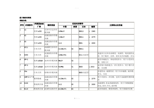
进口钢材对照表
具有优良的耐蚀性,高的力学强度和耐磨性,并有优良的镜面抛光性
48
M310
奥地利百禄
耐蚀镜面塑料模具钢
4Cr13型
具有优良的耐蚀性,耐磨性,镜面抛光性,用于透明部件及光学产品模具
49
NAK55
日本大同
镜面预硬化塑料模具钢
出厂硬度HRC37~43,切削加工性能好,用于高精度镜面模具
50
NAK80
出厂硬度HRC23~33,高级镜面抛光性能,用于彩显玻壳模具、PVC底盘模具
42
HP-1A
韩国重工
普通塑料模具钢
良好的加工性能,加工变型小,用于玩具模具
43
HP-4A
韩国重工
预硬化塑料模具钢
3Cr2Mo
出厂硬度HRC25~32,硬度均匀,加工性能好
44
HP-4MA
韩国重工
预硬化塑料模具钢
P20改良型
近似718
34
CLC2 7 3 8 HH
法国USINOR
高级镜面塑料模具钢
比CLC2738洁净度更高,硬度更均匀,模具性能更佳,寿命长
35
G-STAR
日本大同
耐蚀塑料模具钢
出厂硬度HRC33~37,具有良好的耐蚀性和切削加工性
36
GSW-2 0 8 3
德国德威
耐蚀塑料模具钢
4Cr13型
具有良好的耐蚀性,用于PVC材料模具
日本大同
镜面预硬化塑料模具钢
出厂硬度HRC37~43,镜面抛光性能好,用于高精度镜面模具
51
P20
美国AISI
预硬化塑料模具钢
3Cr2Mo
1.2330
在我国广泛应用,出厂硬度HRC30~42,适用于大中型精密模具
CAS号413611-93-5_10074-G5_MedBio_物理性质

1、产品物理参数:
常用名
10074-G5
英文名
10074-G5
CAS号
413611-93-5
分子量
332.313
密度
1.4±0.1 g/cm3
沸点
538.6±60.0 °C at 760 mmHg
分子式
C18H12N4O3
熔点
无资料
闪点
279.5±32.9 °C
2、技术资料:
体外研究
10074-G5抑制Daudi Burkitt淋巴瘤细胞的生长并破坏c-Myc / Max二聚化。针对Daudi和HL-60细胞的IC50值分别为15.6和13.5μM[1]。10074-G5在区域Arg363-Ile381中结合Myc肽Myc353-437,Kd值为2.8μM。10074-G5结合在由诱导螺旋结构域(Leu370-Arg378)的N末端的扭结(Asp379-Ile381)产生的空腔中[3]。
≥98%
品牌
货号
中文名称
英文名称
CAS
包装
纯度
MedBio
MED11457
CDK inhibitor II
CDK inhibitor II
1269815-17-9
50mg
≥98%
品牌
货号
中文名称
英文名称
CAS
包装
纯度
MedBio
MED11591
(S)-CCG-1423
(S)-CCG-1423
None
体内研究
静脉注射20 mg / kg小鼠的血浆半衰期为10074-G5,为37分钟,血药浓度峰值为58μM,比肿瘤峰值浓度高10倍[1]。
3、同类产品列表:
金属材料记号対照表
TOPBACK
S50C 1049 C50
S55C 1055 C55
◆機械構造用マンガン鋼鋼材及びマンガンクロム鋼鋼材
JIS AISI DIN
SMn420 1522 -
SMn433 1536 -
SMn438 1541 -
SMn443 1544 -
SMnC420 - -
SMnC443 - -
SUH3 - -
SUH4 - -
SUH11 - -
SUH600 - -
◆ステンレス鋼(フェライト系)
JIS AISI DIN
SUS405 AISI 405 DINX6CrAl13
SUS429 AISI 429 -
SUS430 AISI 430 DINX6Cr17
FC100 20 GG-10
FC150 25 GG-15
FC200 30 GG-20
FC250 35 GG-25
FC300 40 GG-30
FC350 50 GG-35
◆耐熱鋼(フェライト系)
JIS AISI DIN
SUH21 - DINCrAl1205
SUH409 AISI 409 DINX6CrTi12
◆ステンレス鋼(オーステナイト系)
JIS AISI DIN
SUS201 AISI 201 -
SUS202 AISI 202 -
SUS301 AISI 301 -
SUS302 AISI 302 -
SUS302B AISI 302B -
SUS303 AISI 303 DINX10CrNiS189
◆ニッケルクロムモリブデン鋼鋼材
世界钢号对照
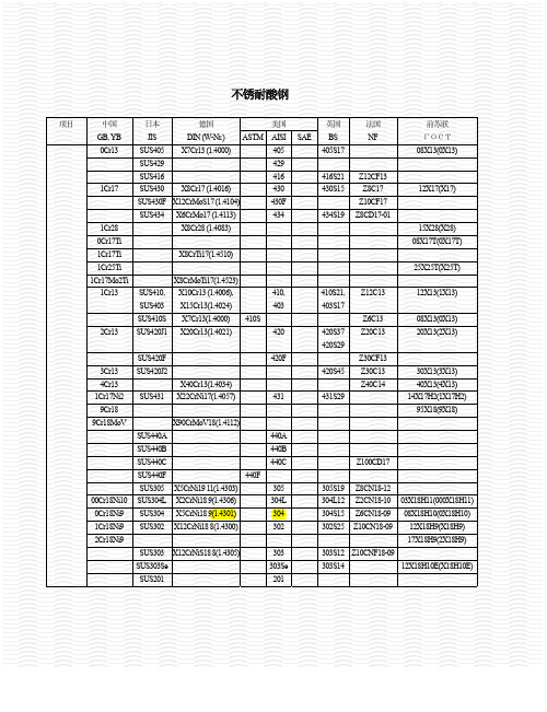
项目 中国 GB, YB 0Cr13 日本 JIS SUS405 SUS429 SUS416 1Cr17 SUS430 SUS434 1Cr28 0Cr17Ti 1Cr17Ti 1Cr25Ti 1Cr17Mo2Ti 1Cr13 SUS410, SUS403 SUS410S 2Cr13 SUS420J1 SUS420F 3Cr13 4Cr13 1Cr17Ni2 9Cr18 9Cr18MoV SUS440A SUS440B SUS440C SUS440F SUS305 00Cr18Ni10 0Cr18Ni9 1Cr18Ni9 2Cr18Ni9 SUS303 X12CrNiS18 8(1.4305) SUS303Se SUS201 303 303Se 201 303S12 Z10CNF18-09 303S14 12X18H10E(X18H10E) SUS304L SUS304 SUS302 X5CrNi19 11(1.4303) X2CrNi18 9(1.4306) X5CrNi18 9(1.4301) X12CrNi18 8(1.4300) 440F 305 304L 304 302 305S19 304L12 304S15 302S25 Z8CN18-12 Z2CN18-10 Z6CN18-09 Z10CN18-09 03X18H11(000X18H11) 08X18H10(0X18H10) 12X18H9(X18H9) 17X18H9(2X18H9) X90CrMoV18(1.4112) 440A 440B 440C Z100CD17 SUS431 SUS420J2 X40Cr13(1.4034) X22CrNi17(1.4057) 431 431S29 X8CrMoTi17(1.4523) X10Cr13 (1.4006), X15Cr13(1.4024) X7Cr13(1.4000) X20Cr13(1.4021) 410S 420 420F 420S45 420S37 420S29 Z30CF13 Z30C13 Z40C14 30X13(3X13) 40X13(4X13) 14X17H2(1X17H2) 95X18(9X18) 410, 403 410S21, 403S17 Z6C13 Z20C13 08X13(0X13) 20X13(2X13) Z12C13 12X13(1X13) X8CrTi17(1.4510) 25X25T(X25T) X8Cr17 (1.4016) X6CrMo17 (1.4113) X8Cr28 (1.4083) SUS430F X12CrMoS17 (1.4104) 德国 DIN (W-Nr.) X7Cr13 (1.4000) 美国 ASTM AISI 405 429 416 430 430F 434 434S19 416S21 430S15 Z12CF13 Z8C17 Z10CF17 Z8CD17-01 15X28(X28) 08X17T(0X17T) 12X17(X17) SAE 英国 BS 405S17 法国 NF 前苏联 ГОСТ 08X13(0X13)
中日部分黑色金属材料对照表

中日部分黑色金属材料对照表(参考) 返回散料机械金屬材料記號對照表機械構造用碳鋼鋼材鎳鉻鉬鋼鋼材机械零件所用金属材料多种多样,为了使生产、管理方便、有序,有关标准对不同金属材料规定了它们牌号的表示方法,以示统一和便于采纳、使用。
钢铁产品牌号表示方法(参照GB/T221—2000)--标准的基本概况GB/T221—2000标准是参照国外钢铁产品牌号表示方法和国内钢铁产品牌号表示方法变化(如Q345代替16Mn)等情况修订后,于2000年4月1日发布,并于2000年11月1日开始实施。
--主要技术内容变动情况(1)由于一些钢铁产品牌号有它们专用的标准,故取消了原标准中铁合金、铸造合金、高温合金、精密合金、耐蚀合金和铸铁、铸钢、粉末材料等牌号表示方法。
(2)一些新的钢铁产品的出现,更加完善了原标准。
新标准增加了脱碳低磷粒铁、含钒生铁、铸造耐磨生铁、保证淬透性钢、非调质机械结构钢、塑料模具钢、取向硅钢(电讯用)等牌号表示方法。
(3)对不适应科技发展和与生产不协调的一些用钢牌号作了彻底改变或修改。
如碳素结构钢A3改为Q235,低合金高强度结构钢16Mn改为Q345等。
对不锈钢、耐热钢和冷轧硅钢等的牌号表示方法也做了修改。
(4)原标准中“钢铁产品牌号表示方法举例”的表3,因不适用于新标准而被删除。
--钢铁产品牌号表示方法的基本原则(1)凡国家标准和行业标准中钢铁产品的牌号均应按GB/T221—2000标准规定的牌号表示方法编写。
凡不符合规定编写的钢铁产品牌号,应在标准修订时予以更改,一些新的钢铁产品,其牌号也应按此予以编写牌号。
(2)产品牌号的表示,一般采用汉语拼音字母,化学元素符号和阿拉伯数字相结合的方法来表示。
(3)采用汉语拼音字母表示产品名称、用途、特性和工艺方法时,一般从代表产品名称的汉语拼音中选取第一个字母。
当和另一个产品所选用的字母重复时,可改用第二个字母或第三个字母,或同时选取两个汉字中的第一个拼音字母。
74649-1004中文资料
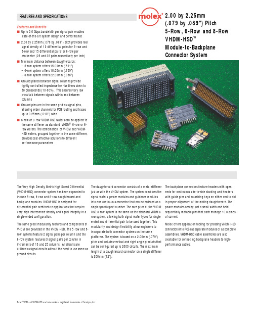
FEATURES AND SPECIFICATIONS2.00 by 2.25mm (.079 by .089") Pitch 5-Row, 6-Row and 8-Row VHDM-HSD ™Module-to-BackplaneConnector SystemFeatures and Benefitss Up to 5.0 Gbps bandwidth per signal pair enables state-of-the-art system design and performance s2.00 by 2.25mm (.079 by .089”) pitch provides real signal density of 10 differential pairs for 5-row and 6-row and 15 differential pairs for 8-row per centimeter (25 and 38 pairs respectively per inch) sMinimum distance between daughtercards:– 5-row system offers 15.00mm (.591")– 6-row system offers 18.00mm (.709")– 8-row system offers 22.00mm (.866")sGround planes between signal columns provide tightly controlled impedance for rise times down to 50 picoseconds (10-90%). This ensures very low cross talk between signals within and between columnssGround pins are in the same grid as signal pins, allowing wider channels for PCB routing and traces up to 0.25mm (.010”) wides6-row or 8-row VHDM-HSD wafers can be applied to the same stiffener as standard VHDM ® 6-row or 8-row wafers. The combination of VHDM and VHDM-HSD wafers, grouped together in the same stiffener, provides cost effective solutions to different performance parametersThe Very High Density Metric High Speed Differential (VHDM-HSD) connector system has been expanded to include 5-row, 6-row and 8-row daughtercard and backplane modules. VHDM-HSD is designed for differential-pair architecture applications that require very high interconnect density and signal integrity in a single-ended configuration.The same great modularity features and components ofVHDM are provided in the VHDM-HSD. The 5-row and 6-row systems feature 2 signal pairs per column and the8-row system features 3 signal pairs per column inincrements of 10 and 25 columns. All circuits areutilized as signal circuits without the need to use some asground circuits.The daughtercard connector consists of a metal stiffener just as with the VHDM system. The system combines the signal wafers, power modules and guidance modules into one continuous connector that can be ordered as a single specific part number. The card pitch of the VHDM-HSD 8-row system is the same as the standard VHDM 8-row system, allowing both signal wafer types for single ended and differential pair to be used together. Thismodularity and design flexibility allow engineers toincorporate both connector systems on the sameplatforms. The system is based on a 2.00mm (.079")pitch and includes vertical and right angle products thatcan be configured up to 2000 circuits. The maximumlength of a daughtercard connector on a single stiffeneris 300mm (12").The backplane connectors feature headers with open ends for continuous side-to-side stacking and headers with guide pins and polarizing keys on either end to aid in proper alignment of the mating daughtercard. The power modules occupy just a small width and hold sequentially matable pins that each manage 10.0 amps of current.Molex offers application tooling for pressing VHDM-HSD connectors into PCBs as separate modules or as complete assemblies. VHDM-HSD cable assemblies are also available for connecting backplane headers to high-performance cables.Note: VHDM and VHDM-HSD are trademarks or registered trademarks of Teradyne,Inc.元器件交易网FEATURES AND SPECIFICATIONS2.00 by 2.25mm (.079 by .089") Pitch 5-Row, 6-Row and 8-Row VHDM-HSD ™Module-to-Backplane Connector SystemPress Fit Right Angle ReceptacleApplicationsThe VHDM-HSD products are used in very high speed, short rise-time, high circuit count applications connecting daughtercards to the backplane:s Network Switches s Routerss Computer Serverss Telecommunication Equipment sInternetworking DevicesORDERING INFORMATIONDaughtercard AssemblyConfiguration 5-Row 6-Row 8-Row Signal wafers, power modules and guide modules sequentiallyassigned by application VHDM-HSD wafers74670-XXXX 74880-XXXX 74680-XXXX Combination of VHDM and VHDM-HSD wafers74686-XXXX 74886-XXXX74686-XXXXBackplane Header Signal Module Standard Loaded Pin Height 0.76µm (30µ”) Gold5-Row6-Row8-Row10-Column 25-Column 10-Column 25-Column 10-Column 25-Column Open Ended4.25mm (.167”)74695-100374695-250374979-100374979-250374649-100374649-25034.75mm (.187”)74695-100174695-250174979-100174979-250174649-100174649-25015.15mm (.203”)74695-100474695-250474979-100474979-250474649-100474649-25046.25mm (.266”)74695-100274695-250274979-100274979-250274649-100274649-2502Left Guide PinNo Polarizing Key 4.25mm (.167”)74696-100374696-2503––74650-100374650-25034.75mm (.187”)74696-100174696-2501––74650-100174650-25015.15mm (.203”)74696-100474696-2504––74650-100474650-25046.25mm (.266”)74696-100274696-2502––74650-100274650-2502Left Guide Pin“A” Polarizing Key 4.25mm (.167”)74696-101374696-2513––74650-101374650-25134.75mm (.187”)74696-101174696-2511––74650-101174650-25115.15mm (.203”)74696-101474696-2514––74650-101474650-25146.25mm (.266”)74696-101274696-2512––74650-101274650-2512Right Guide PinNo Polarizing Key 4.25mm (.167”)74697-100374697-2503––74651-100374651-25034.75mm (.187”)74697-100174697-2501––74651-100174651-25015.15mm (.203”)74697-100474697-2504––74651-100474651-25046.25mm (.266”)74697-100274697-2502––74651-100274651-2502Right Guide Pin“A” Polarizing Key 4.25mm (.167”)74697-101374697-2513––74651-101374651-25134.75mm (.187”)74697-101174697-2511––74651-101174651-25115.15mm (.203”)74697-101474697-2514––74651-101474651-25146.25mm (.266”)74697-101274697-2512––74651-101274651-2512Backplane Power and Guide Components5-Row and 6-Row 8-Row Power Module 74029-600074029-8000Keying Post 74069-001074069-0010Guide Pin74076-0001/000274076-0001/0002Americas Headquarters Lisle, Illinois 60532 U.S.A.1-800-78MOLEX amerinfo@ Far East North Headquarters Yamato, Kanagawa, Japan 81-462-65-2324feninfo@ Far East South Headquarters Jurong, Singapore 65-6-268-6868fesinfo@ European Headquarters Munich, Germany 49-89-413092-0eurinfo@ Corporate Headquarters 2222 Wellington Ct.Lisle, IL 60532 U.S.A.630-969-4550Visit our Web site at /product/backplan/hsd.htmlOrder No. USA-158 Rev. 2Printed in USA/2.5K/JI/JI/2003.03©2003, MolexNote: VHDM and VHDM-HSD are trademarks or registered trademarks of Teradyne,Inc.元器件交易网。
莫索尼啶-化学品安全说明书
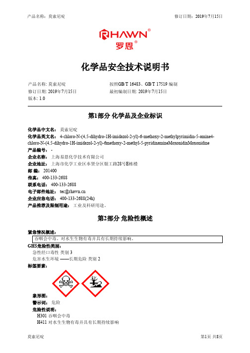
化学品安全技术说明书产品名称: 莫索尼啶按照GB/T 16483、GB/T 17519 编制修订日期: 2019年7月15日最初编制日期: 2019年7月15日版本: 1.0第1部分化学品及企业标识化学品中文名:莫索尼啶化学品英文名: 4-chloro-N-(4,5-dihydro-1H-imidazol-2-yl)-6-methoxy-2-methylpyrimidin-5-amine4-chloro-N-(4,5-dihydro-1H-imidazol-2-yl)-6methoxy-2-methyl-5-pyridinamineMoxonidinMoxonidine 产品编号: -企业名称:上海易恩化学技术有限公司企业地址:上海市化学工业区奉贤分区银工路28号E栋楼邮编: 201400传真: 400-133-2688联系电话: 400-133-2688电子邮件地址:企业应急电话: 400-133-2688(24h)产品推荐及限制用途:工业及科研用途。
第2部分危险性概述紧急情况概述:吞咽会中毒。
对水生生物有毒并具有长期持续影响。
GHS危险性类别:急性经口毒性类别 3危害水生环境 ——长期危险类别 2标签要素:象形图:警示词:危险危险性说明:H301 吞咽会中毒H411 对水生生物有毒并具有长期持续影响防范说明:预防措施:—— P264 作业后彻底清洗。
—— P270 使用本产品时不要进食、饮水或吸烟。
—— P273 避免释放到环境中。
事故响应:—— P301+P310 如误吞咽:立即呼叫解毒中心/医生—— P321 具体治疗 ( 见本标签上的…… )。
—— P330 漱口。
—— P391 收集溢出物。
安全储存:—— P405 存放处须加锁。
废弃处置:—— P501 按当地法规处置内装物/容器。
物理和化学危险:无资料健康危害:吞咽会中毒。
环境危害:对水生生物有毒并具有长期持续影响。
第3部分成分/组成信息组分浓度或浓度范围(质量分数,%)CAS No.4-chloro-N-(4,5-dihydro-1H-imidazol-2-yl)-6-methoxy-2-methylpyrimidin-5-amine4-chloro-N-100%75438-57-2 (4,5-dihydro-1H-imidazol-2-yl)-6methoxy-2-methyl-5-pyridinamineMoxonidinMoxonidine第4部分急救措施急救:吸入:如果吸入,请将患者移到新鲜空气处。
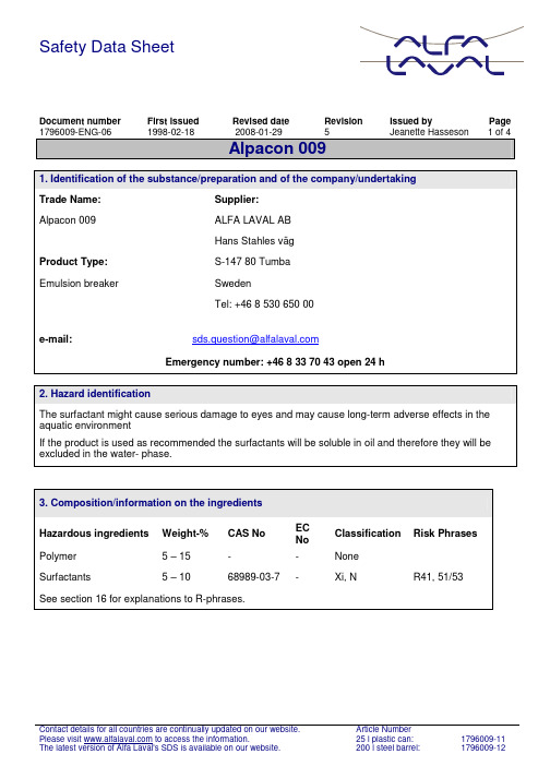
安全数据表(SDS)单号:1796009-ENG-06,发布日期:1998年2月18日,修订日期:2
Safety Data SheetDocument number First issued Revised date Revision Issued by Page 1796009-ENG-06 1998-02-18 2008-01-29 5 Jeanette Hasseson 1 of 4Alpacon 0091. Identification of the substance/preparation and of the company/undertakingTrade Name: Supplier:Alpacon 009 ALFA LAVAL ABHans Stahles vägProduct Type: S-147 80 TumbaEmulsion breaker SwedenTel: +46 8 530 650 00e-mail:Emergency number: +46 8 33 70 43 open 24 h2. Hazard identificationThe surfactant might cause serious damage to eyes and may cause long-term adverse effects in the aquatic environmentIf the product is used as recommended the surfactants will be soluble in oil and therefore they will be excluded in the water- phase.3. Composition/information on the ingredientsHazardous ingredients Weight-% CAS No ECNoClassification Risk PhrasesPolymer 5 – 15 - - NoneSurfactants 5 – 10 68989-03-7 - Xi, N R41, 51/53 See section 16 for explanations to R-phrases.4. First –aid measuresFirst aid – Inhalation Move to fresh air.First aid – Skin contact Wash off with plenty of water.First aid – Eye contact Rinse immediately with tepid water for several minutes. Proceedthe rinse during transport to hospital.Obtain medical attention.First aid – Ingestion Rinse mouth and drink at least 1-2 glasses of water. Do notinduce vomiting.Obtain medical attention.5. Fire- fighting measuresExtinguishing media All extinguishing media are suitable.Special hazards of product The product is not flammable. In case of fire the product mightform hazardous gases as NOx and COx.Protective equipment for fire fighting Not applicable.Fire –fight If the fire is extinguished with water environmental dangeroussubstances might be entering the environment.6. Accidental release measuresPersonal precautions Wear suitable goggles and gloves.Environmental precautions Prevent spills from reaching sewage, wells and watercourses. Spillage Absorb spills with sand, earth or other inert material. Collect andremove for destruction.Large spillage Contact local authority7. Handling and storageHandling Do not mix with other chemicals. Use recommended personalprotection according to section 8.Storage Store in a closed container.8. Exposure control / personal protectionRespiratory protection Appropriate ventilation. Provide facilities for rinsing eyes.Skin protection Protective gloves of nitrile.Eye protection Safety goggles.Ingestion Do not eat or drink during use. Wash hands before eating.9. Physical and chemical propertiesPhysical state Clear liquid.Colour Slightly yellow.Odour Weak smell.Density at 20 °C (g/ml) 1.025± 0.005.pH (as is) at 20 °C 7-9°brix 17.8±0.6.Viscosity at 25 °C (SP01/20 rpm) (cP) 1368±130.Cloud point during heating (°C) 50ºC.Flash point >100 º C10. Stability and reactivityStability The product is stable under normal conditions, but it decomposesat high temperatures.Conditions to avoid Extreme heatMaterials to avoid None knownHazardous decomposition products None known if the product is handled as recommended. In caseof fire the product might form hazardous gases as NOx and COx.11. Toxicological informationSkin At prolonged or frequently use of the product blush might occur.Eyes The product might cause serious damage to eyes.Consumption Low acute toxicity . Might be irritating to mucous membrane.LD50 oral rat 4500mg/kgSkin irritation test rabbit Slightly irritatingEye irritation test rabbit Strongly irritatingSensibillisation Not allergenicGen toxicity Not mutagenic12. Ecological informationLC50 96h (fish) >100mg/lNOEC 96 h (fish) > 100mg/lEC50 48h (Daphnia magna) > 100mg/lNOEC 48 h (Daphnia magna) > 100 mg/lDegradation No readily bodegradable13. Disposal considerationsDisposal of product: State and local disposal regulations may differ from federaldisposal regulations. Always dispose in accordance with federal,state and local requirements.Disposal of containers: Containers should be reused or disposed of by landfill orincineration as appropriate.14. Transport informationNot classified as a hazardous substance according to transport regulations.15. Regulatory informationLabel Symbol(s): XiIrritantRisk Phrases: R36 Irritating to eyes.R52/53 Harmful to aquatic organisms, may cause long-termadverse effects in the aquatic environment.Safety Phrases: S39 Wear eye/ face protection.16. Other informationExplanations to R-phrases in section 2 R41 Risk of serious damage to eyes.R51/53 Toxic to aquatic organisms, may cause long-term adverse effects in the aquatic environment.See also product label for product applications.Important changes have been made in section: 1, 2, 3, 4, 5, 6, 7, 8, 9, 10, 11, 12 and 15.DISCLAIM OF RESPONSIBILITYAlfa Laval provides the information contained herein in good faith but makes no representation as to its comprehensiveness or accuracy. This document is only a guide to the potential hazards of the product. All individuals working with or around the product should be properly trained. Persons coming into contact with the product must be capable of exercising their own independent judgment concerning the conditions or methods of handling, storage and usage of the product. Alfa Laval will not be responsible for claims, losses, or damages of any kind resulting from the information provided in this Safety Data Sheet or the use, handling, storage or disposal of the product. Alfa Laval makes no representations or warranties, either express or implied, including without limitation any warranties of merchantability or fitness for a particular purpose with respect to the information set out herein or the product to which the information refers.。
SAE J1469-1995

告完全是自愿的,并且其任何特别使用的适用性和适宜性包括由此发生的任何专利侵犯都是使用者个人的责任。
SAE至少每5年评审一次此技术报告,在此期间可能会重申,修改或取消此报告。
SAE欢迎你的书面意见和建议。
著作权归汽车工程技术委员会有限公司1995年修订编号. 2-16B&17B 有3处被删除图1-测试顺序示意图2.1适用文件—下面的出版物在确定于此的范围内形成了此规范的一部分2.1.1 ASTM 出版物—可获取的地点:ASTM,1916 Race Street, Philadelphia, PA 19103-1187.ASTM-盐雾测试方案。
3.定义3.1保持气压—驻车气室工作时驻车气室下降气压(制动弹簧扩展)3.2释放气压—在释放驻车气室时驻车气室上升气压(制动弹簧压缩)3.3驻车气室工作—扩展制动弹簧。
3.4驻车气室释放—压缩制动弹簧。
3.5全行程—装置最大行程。
3.6额定行程—装置的最小设定行程。
3.7行车制动助力器—施加主要制动的气动助力器。
3.8驻车制动助力器—控制车辆的机械作用助力器。
3.9组合制动助力器—组合的行车和驻车制动助力器。
3.10零行程—制动助力器推杆必须在缩回位置。
(制动完成)3.11全制动的制动弹簧—在制动助力器内处于最大压缩位置的制动弹簧。
注—此要求按制造商建议程序通过空气作用或机械作用来完成。
4.泄漏率—驻车气室和行车气室。
4.1泄漏—驻车气室。
4.1.1—条件(环境)4.1.1.1 27。
C+11。
C (80。
F+20。
F) 环境温度。
4.1.1.2驻车气室处于释放状态。
4.1.2测试程序4.1.2.1预处理循环—用620-830kPa(计量器)气压完全充满和排空驻车气室反复三次。
4.1.2.2用860-900 kPa(计量器)对驻车气室施加压力。
4.1.2.3允许气压在测试件内保持5min+1min。
4.1.2.4确定气压为860 kPa +7 kPa(125 1bf/in2+1 1bf/in2)(计量器)。
433196中文资料
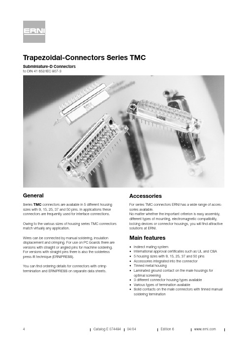
Trapezoidal-Connectors Series TMCGeneralSeries TMC connectors are available in 5 different housing sizes with 9, 15, 25, 37 and 50 pins. In applications these connectors are frequently used for interface connections.Owing to the various sizes of housing series TMC connectors match virtually any application.Wires can be connected by manual soldering, insulation displacement and crimping. For use on PC boards there are versions with straight or angled pins for machine soldering. For versions with straight pins there is also the solderless press-fit technique (ERNIPRESS).You can find ordering details for connectors with crimp terminiation and ERNIPRESS on separate data sheets.AccessoriesFor series TMC connectors ERNI has a wide range of acces-sories available.No matter whether the important criterion is easy assembly, different types of mounting, electromagnetic compatibility, locking devices or connector housings, you will find attractive solutions at ERNI.Main features•Indirect mating system•International approval certificates such as UL and CSA • 5 housing sizes with 9, 15, 25, 37 and 50 pins •Accessories integrated into the connector•Tinned metal housing•Laminated ground contact on the male housings for optimal screening• 3 different connector housing types available•Various types of termination available•Solid contacts on the male connectors with tinned manual soldering terminationSubminiature-D Connectors to DIN 41 652/IEC 807-3D-Sub TerminationPerformance Levels207to DIN 41 652/IEC 807-3MIL-C-24308, CCTU 08-14and IEC-Recommendation 48 B200 mating cyclesContact zone gold-platedterminal zone tinned201as for version 207 butterminal zone gold-plated 107to DIN 41 652/IEC 807-3MIL-C-24308, CCTU 08-14and IEC-Recommendation 48 B500 mating cyclesContact zone gold-platedterminal zone tinned101as for version 107 butterminal zone gold-platedPerformance level 107and101connectors are available on request.Approval CertificatesUL All male and female connectors from this data sheet are approved by the American certification authority …Under-writers Laboratories Inc.“.File no. E 84703CSA All types are listed by the Canadian certification author-ity …Canadian Standards Association“.File Nr. LR 62503 and LR 62504.For ERNIPRESS, crimping and insulation displacement (IDC)there are separate data sheets available.Integrated AccessoriesRiveted nut (see fig. 1)On the version with riveted nut there is a nut riveted into the mounting flanges of the connector so that it cannot twist. The thread is available as a M3 and 4/40" version. This facilitates fitting into housings or front panels.Threaded bolt (see fig. 2)To ensure secure connector locking, a screw locking device is frequently used with threaded bolts. TMC connectors from ERNI are available with riveted threaded bolts. These hexagon bolts are available with internal threads of M3 and 4/40". For the user it means there is no need for loose accessories.Spacer bolt (see fig. 3)Due to the design of the TMC connectors a spacer is required for vertical assembly on pc boards. These parts are supplied by ERNI as individual accessories.Ground pin (see fig. 4)The additional ground pin is designed for connecting up to the pc board chassis contact for example.Spacer bolt with mounting clip (on request)(see fig. 5)These spacer bolts can be snapped into the mounting holes on the pc board. If the holes are plated-through there will also be a solder joint.Ground clip (see fig. 6)For screening contact there are angled ERNI TMC connector ground clips available. These clips are soldered into the mounting holes on the pc board, thus creating a firm chassis connection.Ground bar (see fig. 7)Ground bars on angled connectors are attached to the guide frame on the pc board. This makes it possible to make connection with chassis conductors on the pc board.Ground eyelet (on request) (see fig. 8)With the ground lug the chassis contact can be soldered on.D-Sub Tinned metal housings andlaminated ground contactsThe metal housings on the TMC connectors (standardversions) from ERNI are tinned so as to achieve better contactfor the chassis connection. Specially punched grooves on themetal protective collar of the male connectors ensure reliable contact. Together with the ERNI connector housings in the metallized version and grounding accessories on the connec-tors an optimal electromagnetically compatible application is achieved.Solid punched male contactsDue to a special manufacturing process we are in a positionto offer solid punched male contacts.These versions have a tinned terminal zone and are suitablefor a current-carrying capacity of up to 7.5 A.Guide frame for angled connectorsFor mounting purposes and better guidance of angled TMC connectors with pins for dip-soldering the standard versionsare equipped with a guide frame made of plastic.With this guide frame the connectors can be screwed orriveted onto pc boards.Versions with a guide frame and mounting clip are clipped intothe pc boards and soldered in place.Connector housings for TMC connectorsERNI has also developed connector housings for series TMC interface connectors.• KSG 183housing with engagement locking• KSG 184housing with slide locking• KSG 185housing with engagement and/or screwlocking, integrated codingThese two-shell connector housings are also available inmetallized versions. Together with the ERNI TMC connectors,which have laminated ground contacts, screening is optimized.Versions Numbers of pins 2-rows of 9, 15, 25, 37 and 3-rows of 50 contactsTemperature range -65°...+125°CPermissible humidity Annual average ≤80%, max. 100%Creepage and clearance ≥1,0 mmWorking current 7,5 A max. 5 A max.Test voltage 1250 V rms 1000 V rms Contact resistance ≤2,5 m Ω≤10 m ΩInsulation resistance≥1014ΩShock and vibration proofness No discontinuity at 20 g and 10...2000 HzShock proofness up to 50 gMetal protective collar Tinned steelMR St 4, 1+1 µm Ni, 8±2 µm SNMouldingPBT 30% GVInflammability of the plastic Non flammable as per UL 94 V-0Comperative creepagefigure to CTI 275 / CTI 175 MDIN IEC 112 for PBT Service lifePerformance Level 2 ≥250 mating-cyclesContact force perfemale element0,4 NTMC-male connectors to PerformanceLevels 207 and 201TMC-female connectors to Performance Levels 201TMC-female connectors to Performance Level 207Example of how to orderElectrical and mechanical data023122023123023124023125023126*Dimension tablesPin connectors (P)D-Sub Socket connectors (S)Termination for the versions listed in this data sheetLoe= Solder eyelet tinned (male connector)L= Solder cupTL= Straight solder pin termination for print assemblyLP= Angled solder pin termination for print assembly (with and without guide frame)W= Wire-wrap terminationContact identification (wiring side)9 pins15 pins25 pins37 pins50 pinP S P S P S P S P STMC with manual soldering terminationDimensional drawingsMale connector Female connectorOrdering details004617004620004613004926004615023127023128023129023130023131*004125013522013635004633013844D-SubAssembly detailsTMC with manual solder terminationAssembly cutoutFront assemblyRear assemblyZone of reliable contactTMC with straight dip-solder termination Dimensional drawingsMale connectorFemale connectorDimensional drawings023132023133023019023134023135* 023136023137023138023139023140* 023141023142023143023144023145* 023146023147023148023149023150* 023151023152023153023154023155*003552003553003554003555013920 003634013052003625013702013897 003633013551003626013701013898 003635013550003628013700013892 003636013549003627013699013893Assembly detailsTMC with straight dip-solder terminationPC board hole patterns9 – 37 pin 50 pinSpacer sleeve(available as integrated accessory)PC board Zone of reliablecontact023156023157023158023159023160*013032013033013029013034013641D-SubTMC with straight dip-solder termination (with guide frame)Dimensional drawingsMale connectorFemale connectorOrdering details023166023167023168023169023170*003644004154003643004153013922023171023172023173023174023175*003599013533003622013707013894023181023182023183023184023185*003600013535003623013710013899023186023187023188023189023190*003601013534003624013709013900023176023177023178023**********003598013532003621013708013895D-Sub 023191023192023193023194023195*023196023197023198023199023200023201023202023203023204023205*023206023207023208023209023210023249023250023251023252023253*023279023280023281023282023283 023211023212023213023214023215*023254023255023256023257023258 023216023217023218023219023220*013973434287023259023260023261 023221023222023223023224023225*023262023263023264023265023266 023226023227023228023229023230*003585004225003608023367023268 023284023285023286023287023288*003584013541003464023304023305 023289023290023291023292023293*003583004925003606023306434705 433196023231023232023233023234*433197023049023082023269023270 023235023236023237023238023239*023104023271023272023273023274For further accessories and other combination options please consult ERNI’s local office sales. Assembly detailsTMC with straight dip-solder terminationPC board hole patterns9 – 37 pin 50 pinPC boardZone of reliablecontact013966023240023241023242023243023244023245023246023247023248*023294023295023296023297023298*023299023300023301023302023298*013965023275003605023276004869003581013542013834023277023278003579013014023307004448023308003580023309003603023310023311D-SubSpecial version with solder pitch of 2.84 mm between the rows TMC with angled dip-solder termination (solder pitch 2.84 mm)Dimensional drawingsMale connectorFemale connectorOrdering details about special version with solder pitch of 2.84 mmDue to the wider pitch between the rows, there is more space for conductors on the PC board. The clearance and creepage ages are greater on these versions.PC board hole patterns9 – 37 pin023317023318023319023320023*********TMC with angled dip-solder termination (without guide frame)Dimensional drawingsMale connectorFemale connectorOrdering detailsIntegrated accessories are also available on request for TMC connectors with angled terminals without guide frame.For assembly, an assembly comb is available on request.023322023323023324023325023326*013487013525013624013714013930D-SubAssembly detailsTMC with angled dip-soldered termination without guide framePC board hole patterns9 – 37 pin50 pinPC boardZone of reliable contactPC boardTMC with wire wrap terminations Dimensional drawingsMale connectorFemale connectorOrdering detailsScrew locking accessories (for all TMC standard version connectors)Ordering details434831434832434833434830023327023328023329023330023331*013492013553013632013698013928。
(年7月整理)ASME与国产材料对照表

(年7月整理)ASME与国产材料对照表与国产材料与ASME材料对照表checklitofGBmaterialandASMEmaterial国产材料GBmaterialASME材料ASMEmaterial材料牌号MaterialtrademarkQ235-C板板plate材料牌号MaterialtrademarkSA-414Cσb375σb380σS235σS230材料牌号Materialtrademark20R板板plate材料牌号MaterialtrademarkSA-283DSA-51560SA-51660σb400σb415σS235σS230材料牌号Materialtrademark20g板板plate材料牌号MaterialtrademarkSA-283DSA-51560SA-51660σb400σb415σS225σS220材料牌号Materialtrademark16Mn板板plate材料牌号MaterialtrademarkSA-537SA-738Cσb485σS305σS315材料牌号Materialtrademark20#管子piping材料牌号MaterialtrademarkSA-53S、Bσb392σb415σS226σS240材料牌号Materialtrademark20G管子piping材料牌号MaterialtrademarkSA-53S、Bσb402σb415σS216σS240材料牌号Materialtrademark15CrMo板板plate材料牌号MaterialtrademarkSA-662Cσb450σb485σS295σS295材料牌号Materialtrademark15CrMo管子piping材料牌号MaterialtrademarkSA-178DSA-106CSA-210Cσb485σS226σS275※A516Gr。
60-16MnR热轧板,A516Gr。
EN 14399-5
目录前言 (3)绪言 (3)1、范围 (3)2、参考标准 (4)3、尺寸 (4)4、名称和参考标准 (5)5、名称 (5)6、标记 (5)参考书目 (5)前言该文件由(EN14399-1:2005)CEN/TC 185技术委员会准备,“螺纹和无螺纹机械紧固件和附属产品”由德国秘书处保存。
欧共体标准应作为一个国家标准的身份,最迟在2005年9月被发行或认证。
并且有争议的标准最迟在2005年9月被取消。
该文件已由欧洲委员会和欧洲自由贸易协会授予了CEN准备,并支持EC指示的必要要求。
绪论但是,把两个系统中的螺栓/螺母混合组装是不允许的。
因此,两个系统中的不同的螺栓和螺母都对应此标准中的单个标准。
同一系统中螺栓/螺母/的标记是一样的。
表一、螺栓/螺母/垫圈装配系统预载荷螺栓的装配,对不同的加工方法和润滑很敏感。
因此,装配组件由同一个能对装配组件负责的制造商提供是非常重要的。
同样的道理,组件的表面处理由同一个制造商来提供也是很重要的。
除了组件的机械性能,如果装配有在一个严密的流程,装配组件功能要求的预载荷能够达到。
出于这个目的,就用一个合适的测试方法,来证明装配组件的功能是否完全满足要求。
应指出,和ISO272相比较,M12和M20的对边(大系列)已分别改为22mm和32mm,这样修改是合理的,原因如下:对M12对边21mm的螺栓,在结构特殊的条件下,尤其是在垫圈对螺栓轴线偏心的情况下,螺栓头或螺母的下面有拧紧的压缩抗力可能会变得很大。
对M20的螺栓,34mm的对边在生产时很难加工,改为32mm首先在经济学上是有根据的。
但要指出,32mm的对边在欧洲已被很普遍的执行了。
随着时间的发展,产品标准EN 14399-3到EN 14399-6是唯一按照EN 14399-1的一般要求来做的,尽管如此,这将适用于更多的产品----安装螺栓----沉头螺栓----预载荷垫圈用于高强度钢结构的螺栓都在准备之中。
1、范围这份文本和EN 14399-1一起,制定了经淬硬和回火的垫圈。
