LOC111中文资料
MIKE11_UserManual_目录_中文翻译

MIKE 11 用户手册目录中文翻译模拟编辑器1 模拟编辑器1.1模型1.1.1模型1.1.2模拟模式1.2输入1.3模拟1.3.1 模拟时段1.3.2 初始条件1.4 结果1.5 开始河网编辑器2 河网编辑器2.1 绘图视图窗口2.1.1 河网编辑工具栏2.1.2 主菜单--文件2.1.3 主菜单--编辑2.1.4 主菜单--视图2.1.5 主菜单--河网2.1.6 主菜单--图层2.1.8 主菜单--窗口2.1.9 主菜单--帮助2.2 列表视图:河网2.2.1 点2.2.2 河流2.2.3 校准线2.2.4 节点2.3 列表视图:建筑物2.3.1 建筑物概述2.3.2 组合建筑物定义2.3.3 建筑物类型定义2.3.4 建筑物几何形状定义2.3.5 建筑物轮廓2.3.6 堰2.3.7 涵洞2.3.8 泵2.3.9 桥梁2.3.10 整治建筑物2.3.11 可控建筑物2.3.12 溃坝建筑物2.3.13 溃坝侵蚀2.3.14 用户自定义建筑物2.3.15 列表建筑物2.3.16 能量损失2.4 列表视图:演进2.4.1 明渠演进2.4.2 洪水控制流量和流量比2.4.3 洪水控制水位/流量和水位/体积过程曲线 2.4.4 转接2.4.5 运动学演进方法2.5 列表视图:降雨径流/地下水链接 2.5.1 MIKE SHE链接2.5.2降雨径流链接2.6 列表视图:计算网格点断面编辑器3 断面编辑器3.1 原始数据视图3.1.1 断面基本数据3.1.2 原始数据:树形视图3.1.3 原始数据:列表视图3.1.4 原始数据:绘图视图3.1.5 原始数据编辑器附加特性 3.1.6 “断面”下拉菜单3.1.7 “设置”下拉菜单3.2 数据处理视图3.2.1 数据处理:树形视图3.2.2数据处理:列表视图3.2.3数据处理:绘图视图3.2.4数据处理:水位按钮3.3 利用文件输入菜单导入数据3.3.1 导入原始数据3.3.2 导入处理过的数据3.3.3 导入断面标记坐标3.4 利用文件输出菜单导出数据3.5 多断面绘制边界编辑器4 边界编辑器4.1 边界编辑器概述4.1.1 边界列表—上部窗口4.1.2 边界类别定义4.1.3 边界类型、数据类型和文件/数值定义4.2 边界编辑器工具4.2.1 快速建立粒级边界4.2.2 快速建立AD边界4.2.3 复制点源边界4.2.4 比例系数4.3 用户自动升级MIKE 11 2002版本或早期版本降雨径流编辑器5 降雨径流编辑器5.1 模型子流域定义5.2 NAM降雨径流模型5.2.1 表层-根区5.2.2 地下水5.2.3 融雪5.2.4 灌溉5.2.5 初始条件5.2.6 自动率定5.3 UHM5.4 SMAP5.5 Urban5.6 洪水估算手册5.7 DRiFt5.8 时间序列5.9 参数菜单5.10 流域视图5.11 结果综述5.12 RR-编辑器使用步骤水动力编辑器6 水动力参数编辑器6.1 初始设置6.2 风场6.3 河床阻力6.3.1 统一处理方法6.3.2 三分区方法6.3.3 植被和河床阻力6.4 河床阻力工具箱6.5 波方法6.5.1 完全动力波和高阶完全动力波 6.5.2 扩散波6.5.3 运动波6.6 默认值6.6.1 计算方案6.6.2 开关6.7 准稳态6.7.1 计算参数6.7.2 稳态选项6.7.2 收缩和扩展损失系数6.8 热平衡6.9 分层6.10 输出时间序列6.10.1 生成时间序列文件 6.10.2 文本文件设置6.10.3 输出时段6.10.4 输出内容6.10.5 输出计算点6.11 地图6.12 地下水泄漏6.13 延伸长度6.14 附加输出6.15 洪泛区阻力6.16 用户自定义标记6.17 侵蚀6.17.1 迭代6.17.2 位置6.17.3 侵蚀方法6.17.4 侵蚀位置6.17.5 参数减少6.17.6 目标值6.17.7 侵蚀模拟概述6.17.8 侵蚀站点概述6.17.9 侵蚀模拟一般指导线6.18 MIKE 12 参数6.19 MIKE 12初始设置6.20 混合参数6.21 W.L Incr-曲线6.22 W.L Incr-Sand Bars对流-扩散(AD)编辑器7 对流-扩散编辑器7.1 模块概述7.1.1 AD模块7.1.2 AD方程7.1.3 粘性沙传输模块(CST)7.1.4 高级粘性沙传输模块(ACST) 7.2 成分7.3 扩散7.4 初始成分7.5 衰减7.6 粘性ST7.6.1 单层粘性模型7.6.2 多层粘性模型7.6.3 粘性泥沙运输动力学概述7.7 泥沙分层7.7.1 源自外部文件的初始厚度7.9 非粘性ST7.10 扩散,MIKE127.11 附加输出,MIKE 127.12 AD模拟,附加特性7.12.1可选择的方法:ULTIMATE 方法7.12.2 通过MIKE11.ini文件激活AD模拟特性水质 EcO Lab编辑器8水质 EcO Lab编辑器8.1 定义模型8.2 状态变量8.3 常量8.4 作用力8.5 辅助变量8.6 处理8.7 辅助输出泥沙输运编辑器9 泥沙输运编辑器9.0.1 泥沙输运模拟:模拟模式9.0.2 输运模型9.1 泥沙粒径9.2 输运模型9.2.1 模型参数9.2.2 特定输运模型的特性9.2.3 河床高程更新方法9.3 率定参数9.4 ST分级数据9.5 节点处泥沙预先分布9.6 无输运河道设置9.7 不冲底部高程9.8 初始沙丘尺寸9.9 ST模拟:附加特性洪水预报编辑器10 洪水预报编辑器10.1 基本定义10.2 预报10.3 边界估算10.4 更新设置数据同化编辑器11 数据同化编辑器11.1概述11.2 测量值11.3 方程编辑器11.4 边界统计11.5 标准差编辑器11.6 输出11.7 不确定性分析步骤11.8 卡尔曼滤波方法步骤11.9 权重函数方法步骤11.10 实例批处理编辑器12 批处理编辑器12.1 建立批处理模拟。
徕卡Leica_Viva系列( TS11_TS15)用户手册
64
4 检验 & 校准
67
4.1 概述
67
4.2 准备工作
70
4.3 组合校准 (l, t, i, c 和 ATR)
72
4.4 横轴倾斜误差校准 (a)
77
4.5 校准仪器和基座的圆水准器
81
4.6 校准棱镜杆上的圆水准器
83
4.7 检查仪器激光对中器
84
4.8 校准激光指向
86
4.9 三脚架维修
90
服务 我的产品 我的维修 我的支持 我的培训
说明
简单地将您和贵公司拥有的 Leica Geosystems 产品添加进来。查看您 的产品的详细信息,购买附加选项或客户关怀包 (CCPs),升级最新的 软件并获取最新的文档。
查看您的产品在 Leica Geosystems 维修中心的维修历史以及详细信 息。如果您的产品目前在 Leica Geosystems 维修中心,那么可以查看 它当前的维修状态以及预计维修截止日期。
7.10.5 SLR1,SLR2,SATEL SATELLINE-3AS
157
7.10.6 SLR5, SATEL SATELLINE M3-TR1
159
7.10.7 SLR3-1,SLR3-2,Pacific Crest ADL
161
TS11/TS15, 目录
9
TS11/TS15, 目录
10
7.10.8 SLG1,Telit UC864-G
仪器的型号和序列号标注在仪器标签上。 请将仪器型号和序列号填写在下面。当您需要与经销商或 Leica Geosystems 授权的维修 部门联系时,将会用到这些信息。
类型: 序列号:
GSM11.11中文版(ICS33.060.50)
资料来源:ETSI TC-SMG 参考资料:RE/SMG-091111PR4 ICS:33.060.50GSM全球移动通信系统数字蜂窝电信系统(PHASE 2)个人身份鉴别模块——移动设备(SIM—ME)接口规范(GSM 11.11)ESTI欧洲电信标准化机构目录前言1综述Scope2参考标准References3定义、缩写和符号Definitions,Abbreviations and symbols3.1定义Definitions3.2缩写Abbreviations3.3符号Symbols4物理特性Physical characteristics4.1格式和布局Format and Layout4.1.1插入式SIM Plug-in SIM4.2卡操作的温度范围Temperature range for card operation4.3触点Contacts4.3.1触点位置Provision of contacts4.3.2激活与反激活Activation and Dectivation4.3.3惰性接触Inactive contacts4.3.4接触压力Contact pressure4.4优先考虑Precedence4.5静电保护Static Protection5电信号和传输协议Electronic signals and ransmission protocols5.1电源Vcc(触点C1)Supply voltage Vcc (contact C1)5.2复位(RST)(触点C2)Reset(RST) (contact C2)5.3编程电压Vpp(触点C6)Programming voltage Vpp (contact C6)5.4时钟CLK(触点C3)Clock CLK (contact C3)5.5I/O (触点C7)I/O (contact C7)5.6说明States5.7波特率Baudrate5.8复位响应(ATR)Answer To Reset (ATR)5.8.1结构和内容Structure and contents5.8.2PTS过程PPS procedure5.9位/字符宽度和采样时间Bit/character duration and sampling time5.10错误处理Error handling6逻辑模型Logical Model6.1简述General description6.2文件识别File identifier6.3专用文件Dedicated Files6.4基本文件Elementary Files6.4.1透明的EF Transparent EF6.4.2线性固定的EF Linear fixed EF6.4.3循环EF Cyclic EF6.5选择一个文件的方法Methods for selecting a file6.6保留的文件ID Reservation of file IDs7安全特征Security Features7.1认证和密钥产生的过程Authentication and cipher key generation procedure7.2算法和运算Algorithms and processes7.3文件存取条件File access conditions8功能描述Description of the functions8.1SELECT8.2STATUS8.3READ BINARY8.4UPDATE BINARY8.5READ RECORD8.6UPDATE RECORD8.7SEEK8.8INCREASE8.9VERIFY CHV8.10CHANGE CHV8.11DISABLE CHV8.12ENABLE CHV8.13UNBLOCK CHV8.14INV ALIDATE8.15REHABILITATE8.16RUN GSM ALGORITHM8.17SLEEP9命令描述Description of the commands9.1映射规则Mapping principles9.2命令编码Coding of the commands9.2.1SELECT9.2.2STATUS9.2.3READ BINARY9.2.4UPDATE BINARY9.2.5READ RECORD9.2.6UPDATE RECORD9.2.7SEEK9.2.8INCREASE9.2.9VERIFY CHV9.2.10CHANGE CHV9.2.11DISABLE CHV9.2.12ENABLE CHV9.2.13UNBLOCK CHV9.2.14INV ALIDATE9.2.15REHABILITATE9.2.16RUN GSM ALGORITHM9.2.17SLEEP9.2.18GET RESPONSE9.3定义和编码Definitions and Coding9.4卡片返回的状态条件Status conditions returned by the card9.4.1对正确执行的命令的响应Response to commands which are correctly executed9.4.2存储管理Memory management9.4.3协议管理Referencing management9.4.4安全管理Security management9.4.5应用无关错Application independent errors9.4.6与可能的状态响应有关的命令Commands versus possible status responses 10基本文件(EF)的内容Contents of the Elementary Files(EF)10.1MF与EF的内容Contents of the Efs at the MF level10.1.1EF ICCID(ICC识别)(ICC Identification)10.2GSM应用层文件的内容Contents of files at the GSM application level10.2.1EF LP(语言参考)(Language preference)10.2.2EF IMSI(IMSI)(IMSI)10.2.3EF KC(密钥Kc)(Ciphering key Kc)10.2.4EF PLMNsel(PLMN选择器)( PLMN selector)10.2.5EF HPLMN(HPLMN搜索周期)(HPLMN search period)10.2.6EF ACMmax (ACM最大值)(ACM maximum value)10.2.7EF SST(SIM服务表)(SIM service table)10.2.8EF ACM(累计呼叫表)(Accumulated call meter)10.2.9EF GID1(组标识1)(Group Identifier Level 1)10.2.10EF GID2(组标识2)(Group Identifier Level 2)10.2.11EF SPN(服务供应商名字)(Service Provider Name)10.2.12EF PUCT (单位价格和货币表)(Price per unit and currency table)10.2.13EF CBMI(小区广播消息识别)(Cell broadcast message identifier selection)10.2.14EF BCCH(广播控制通道)(Broadcast Control Channels)10.2.15EF ACC(存取控制类)(Access control Class)10.2.16EF FPLMN(禁止PLMN)(Forbidden PLMNs)10.2.17EF LOCI (定位信息)(Location information)10.2.18EF AD (内部管理数据)(Administrative data)10.2.19EF phase (阶段识别)(Phase identification)10.3电信层的文件内容Contents of files at the telecom level10.3.1EF AND (缩写的拔号码)(Abbreviated dialling numbers)10.3.2EF FDN(固定的拔号码)(Fixed dialling numbers)10.3.3EF SMS(短信息)(Short Messages)10.3.4EF CCP(容量配置参数)(Capability configuration parameters)10.3.5EF MSISDN(MSISDN)(MSISDN)10.3.6EF SMSP(短信息服务参数)(Short message service parameters)10.3.7EF SMSS (SMS状态)(SMS status)10.3.8EF LND (最后拔打号码)(Last number dialled)10.3.9EF EXT1 (扩展1)(Extension 1)10.3.10EF EXT2(扩展2)(Extension 2)10.4GSM文件(图7)Files of GSM11应用协议Application protocol11.1通用过程General procedures11.1.1读出文件Reading an EF11.1.2更新文件Updating an EF11.1.3增加文件Increasing an EF11.2SIM管理过程SIM management procedures11.2.1SIM初始化SIM initialization11.2.2GSM过程终止GSM session termination11.2.3紧急呼叫代码Emergency Call Codes11.2.4语言参考Language preference11.2.5管理信息请求Administrative information request11.2.6SIM服务表请求SIM service table request11.2.7SIM阶段请求SIM phase request11.3CHV相关过程CHV related procedures11.3.1CHV检验CHV verification11.3.2CHV值替换CHV value substitution11.3.3CHV失效CHV disabling11.3.4CHV有效CHV enabling11.3.5CHV解锁CHV unblocking11.4GSM安全相关的过程GSM security related procedures11.4.1GSM算法计算GSM algorithms computation11.4.2IMSI请求IMSI request11.4.3存取控制请求Access control request11.4.4HPLMN搜索期请求HPLMN search period request11.4.5定位信息Location information11.4.6密钥Cipher Key11.4.7BCCH信息BCCH information11.4.8禁止PLMN Forbidden PLMN11.5个人识别相关的过程Subscription related procedure s11.5.1拔打号码Dialling numbers11.5.2短信息Short messages11.5.3付款建议(AoC)Advice of Charge (AoC)11.5.4容量配置参数Capability configuration parameters11.5.5PLMN选择器PLMN selector11.5.6小区广播消息标识Cell Broadcast message identifier11.5.7组识别1 Group identifier level 111.5.8组识别2 Group identifier level 211.5.9服务供应商姓名Service Provider Name附录A(标准的):插入式SIM (normative)Plug-in SIM附录B(一般参考):FDN过程(informative) FDN procedures附录C(一般参考):在预个人化EF的内容的建议(informative) Suggested contents of the Efs at pre-personlization附录D(一般参考):参考文献(informative)历史前言这份欧洲电信标准(ETS)是由欧洲电信标准化机构(ETSI)下的特别移动组(SMG)技术委员会(TC)所制订的。
sht11中文资料_数据手册_参数
万联芯城专注电子元器件配单服务,只售原装 现货库存,万联芯城电子元器件全国供应,专为终端生产,研发 企业提供现货物料,价格优势明显,万联芯城电子元器件BOM配套 业务,客户提交物料清单,商城进行报价,整单采购可享优惠价 ,订单最快可当天发出,为客户节省采购时间,提高生产效率, 点击进入万度传感器-露点完全校准,数字输出-优秀的长期稳定不需要外部组件-超低功耗表面挂载或4-pin完全互换小尺寸自动功率downSHT1x / SHT7x产品SummaryThe SHTxx是单个芯片相对湿度副多传感器模块组成一个calibrateddigital输出。工业 CMOS工艺与专利微加工(CMOSens®技术)的应用,SHT11确保最高的可靠性和优良的长期稳定性。SHT11该装置包括用于相对湿度的电 容式聚合物传感元件和带隙温度传感器。两者都无缝地连接到一个14位模拟到数字转换器和一个串行接口电路在同一芯片上。这导致 了优越的信号质量,快速的响应时间和对外部干扰(EMC)不敏感,在一个非常有竞争力的价格。每个SHTxx都在一个精密的湿度室中单 独校准,并以一个冷镜湿度计作为参考。校准系数被编程到OTPmemory中。这些系数在测量过程中用于内部校准传感器发出的信号。2 线串行接口和内部电压调节,方便快捷的系统集成。它的小尺寸和低功耗使其成为最苛刻的应用程序的最终选择。该设备以表面可安 装的LCC(无铅芯片载体)或可插入的4针单线式封装方式提供。可根据客户要求提供特定的包装选项。1应用程序hvac_automotive_消费 品_气象站_加湿器_除湿器2.2.1串行时钟输入(SCK) SCK用于同步ena单片机与SHTxx之间的通信。SHT11由于接口是完全静态逻辑的, 所以不存在最小的SCKfrequency.2.2.2串行数据(data)数据三态引脚用于在设备内外传输数据。数据在下降沿后发生变化,在串行时钟 SCK上升沿上是有效的。在传输过程中,当SCK高时,数据线必须保持稳定。为了避免信号争用,微控制器应该只驱动低数据。外部上 拉电阻(例如10 kΩ)需要把信号高。(见图2)微控制器的I/O电路中经常包含有上拉电阻。见表5详细IO特征。(1)每个SHTxx测试完全在RH 精度规格25°C (77°F)和48°C (118.4°F)(2)默认的测量分辨率的14位(温度)和12位(湿度)可以减少到12和8位状态寄存器。2.2.3发送命 令启动传输时,必须发出“传输开始”顺序。它包括在SCK高时降低数据行,然后在SCK上降低脉冲,在SCK高时再次提高数据。接下 来的命令由三个地址位(目前只支持“000”)和五个命令位组成。SHTxx通过在第8个SCK时钟下降沿后将数据引脚拉低(ACK位)来指示 正确接收命令。数据线在第9个SCK时钟的下降边缘后被释放(并上升)。SHT11表2SHTxx命令列表2.2.4测量顺序(RH和T)在发出测量命令 (RH为“00000101”,温度为“00000011”)后,控制器必须等待测量完成。对于8/12/14位的测量,这大约需要11/55/210毫秒。与内部振 荡器的速度相比,精确的时间间隔可达±15%。为了表示测量完成,SHTxx向下拉数据线并进入空闲模式。在重新启动SCK读取数据之 前,控制器必须等待这个“数据就绪”信号。测量数据被存储到读出,因此控制器可以继续执行其他任务并方便地读出。然后传输两 个字节的测量数据和一个字节的CRCchecksum。uC必须通过将数据线拉低来识别每个字节。所有值都是MSB优先,右对齐。(例如,第 5个SCK是msb,对于一个12位的值,对于一个8位的结果,SHT11不使用第一个字节)。通信在rc数据的确认位之后终止。如果不使用 CRC-8校验和,控制器可以在测量数据sb之后通过保持ack高电平终止通信。测量和通信结束后,设备自动返回睡眠模式。警告:为了使 自热温度保持在0.1℃以下,shtxxi的激活时间不应超过10%(例如:max。如果与设备失去通信,以下信号序列将重置其串行接口:在保持数 据高的同时,切换sck9或更多次。这之后必须在下一个命令之前执行“传输开始”顺序。此序列仅重置接口。状态寄存器保存其内容。 图4连接复位顺序2.2.6 CRC-8校验和计算整个数字传输由8位校验和保护。它确保任何错误的数据可以被检测和消除。有关如何计算结 直肠癌的资料,请参阅申请须知“CRC-8校验和计算”。
RPNS090AA1A11X资料

RPN SeriesHall-Effect Rotary Position SensorsDESCRIPTION RPN Series Rotary Position Sensors use a magnetically biased, Hall-effect integrated circuit (IC) to sense rotary movement of the actuator shaft over a set operating range. Rotation of the actuator shaft changes the IC’s position relative to the magnets. The resulting flux density change is converted to a linear output. The IC, together with conditioning and protection circuitry, and two permanent magnets, is sealed in a rugged package of IP67 or greater for durability in most harsh environments. Solid-state Hall-effect technology provides non-contact operation, long service life, low torque actuation and reduced wear-out mechanisms. Eight operating ranges (50°, 60°, 70°, 90°, 120°, 180°, 270° and 360°) are tolerant to over travel and allow use in most common applications. FEATURES • Solid-state Hall-effect technology • Eight operating ranges, up to 360° • Variety of supply voltages and output configurations • Rugged sealed package with integral connector • IP67 or greater • Integrated reverse polarity, short circuit and EMC protection • Single or dual output versions available • Industry-standard termination POTENTIAL APPLICATIONS Position and movement detection of pedals, throttle, gear shift, levers, linkages, suspension and hitches in: • Trucks • Off road vehicles • Industrial vehicles and equipment • Construction vehicles and equipment • Agricultural vehicles and equipment • Cranes Five different supply voltages and eight different output configurations, in either mA or Vdc, improve compatibility with a variety of control systems. Two versions provide dual outputs for use where an additional output may be desired where redundancy and backup is needed. Another potential application includes using one output for an indicator and the second for the control system. Lever versions are available. The easy-to-mount sensor has a mounting flange with two round or oval mounting holes. All products have AMP or Deutsch receptacles.RPN SeriesTable 1. RPNR Redundant (Dual) Output Specifications Characteristic Parameter Operating ranges available 50° (±25°), 90° (±45°) Output available 50° (±25°): Channel 1: 4 mA (left), 20 mA (right); Channel 2: 0.5 Vdc (left), 4.75 Vdc (right) 90° (±45°): Channel 1: 0.25 Vdc (left), 4.75 Vdc (right); Channel 2: 4.75 Vdc (left), 0.25 Vdc (right) Supply voltage range(s) 50° (±25°): Channel 1: 8.5 Vdc; Channel 2: 5 Vdc available 90° (±45°): Channel 1: 10 Vdc to 30 Vdc; Channel 2: 10 Vdc to 30 Vdc Current consumption 20 mA max. Output signal delay 3 ms approx. Accuracy ±1.6% Hysteresis none Linearity RPNR050SDMEC3A21X ±0.35° RPNR090KAAA3A11X ±0.6° Reverse polarity protection yes Operating and storage -40 °C to 125 °C [-40 °F to 257 °F] temperature range EMC 200 V/m ISO 11452-3 6 Expected life 30x10 cycles Protection class IP69K DIN 40050 Housing material PA66 plastic Shaft material stainless steel Termination AMP 1-1419168-1 Mechanical end stop no Table 2. RPNS Single Output Specifications Characteristic Operating ranges available Outputs availableSupply voltage range(s) available Current consumption (maximum) Output signal delay (approx) Reverse polarity protection EMC Operating and storage temperature range Protection class Accuracy Hysteresis Linearity RPNS050BB1A21X, RPNS050FA1A21X RPNS060AC1A21X RPNS070DD1A21X All other listings RPNS120AA1A21X Housing material Shaft material Expected life Termination Mechanical end stopParameter 50° (±25°), 60° (±30), 70° (±35), 90° (±45), 120° (±60), 180° (±90), 270° (±135), 360° (±180) 0.25 Vdc (left), 4.75 Vdc (right) 4 mA (left), 20 mA (right) 0.5 Vdc (left), 4.5 Vdc (right) 20 mA (left), 4 mA (right) 1 Vdc (left), 9 Vdc (right) 3 Vdc (left), 5 Vdc (right) 4.5 Vdc (left), 0.5 Vdc (right) 4.75 Vdc (left), 0.25 Vdc (right) 5 Vdc, 8 Vdc to 30 Vdc, 10 Vdc to 30 Vdc 20 mA 3 ms yes 200 V/m ISO 11452-3 -40 °C to 125 °C [-40 °F to 257 °F] IP67 DIN 40050 ±1.6% none ±0.35° ±0.6 ±1° ±2° ±5° PA66 plastic stainless steel 6 30x10 cycles AMP Superseal 282087-1, Deutsch DT04-3P no2/sensingHall-Effect Rotary Position SensorsFigure 1. RPNR Redundant (Dual) Output Versions (For Reference Only: mm/[in].) RPNR050DMEC3A21X RPNR090KAAA3A11XRFigure 2. RPNS Single Output Versions (For Reference Only: mm/[in].) RPNS050BB1A21X RPNS050FA1A21XReceptacle: AMP Superseal 282087-1 Mating Connector: AMP Superseal 282103 3 Vdc L 4 Vdc 50° 5 Vdc R52 [2.05] 37,7 [1.48] 4,2 [0.17]20°27,7 [1.09] Pinout 1 = Ground 2 = 10 Vdc to 30 Vdc Supply 3 = 3 Vdc to 5 Vdc Output Characteristic Curve 5 5 [0.20]50 [1,97]63 [2.48]32124,8 [0.98]4,12 [0.16] 4,6 [0.18] Ø20 [0.79]8,3 [0.33] Ø2 [0.08]14 [0.55]3 25 0 Angle (°) 25Ø6 [0.24]RPNS060AC1A21XRPNS070DD1A21XHoneywell Sensing and Control3RPN SeriesFigure 2. RPNS Single Output Versions (Continued) RPNS090AA1A11X RPNS090AA1B11ARPNS090AA1B11ARPNS090AA2A11XRPNS090AC1A21XOutput (Vdc)RPNS090AC1A21XRPNS090CA1A11XRPNS090DD2A21XReceptacle: Deutsch DT04-3P Mating Connector: Deutsch DT06-3S 4 mA L 52 [2.05] 12 mA 90° 20 mA ROutput (Vdc)248607WW/YY260121WW/YYRPNS090CA1A11XWW/YY37,7 [1.48]4,2 [0.17]24899020°27,7 [1.09] Pinout 1 = Ground 2 = 8 Vdc to 30 Vdc Supply 3 = 4 mA to 20 mA Output Characteristic Curve 20Output (Vdc)50 [1,97]63 [2.48]5 [0.20]2 3 124,8 [0.98]4,12 [0.16] 4,6 [0.18] Ø20 [0.79]8,3 [0.33] Ø2 [0.08]14 [0.55]4 45 0 Angle (°) 45Ø6 [0.24]4/sensingHall-Effect Rotary Position SensorsFigure 2. RPNS Single Output Versions (Continued) RPNS090EA1A11X RPNS090GA1A21XRPNS120AA1A21XRPNS180DA2A11XReceptacle: Deutsch DT04-3P Mating Connector: Deutsch DT06-3S 12 mA 180°52 [2.05]RPNS120AA1A21XWW/YY37,7 [1.48] 4 mA L Ø5.3 [0.20] 27,7 [1.09] Pinout 1 = Ground 2 = 10 Vdc to 30 Vdc Supply 3 = 4 mA to 20 mA Output Characteristic Curve 20 5 [0.20] 50 [1,97] 20 mA R24821363 [2.48]2 3 124,8 [0.98]Output (Vdc)4,12 [0.16] 4,6 Ø6 [0.18] [0.24] 90 0 Angle (°) 908,3 [0.33] Ø2 [0.08] Ø20 [0.79]14 [0.55]0RPNS180HD1B11ARPNS270DA1A21XHoneywell Sensing and Control5RPN SeriesFigure 2. RPNS Single Output Versions (Continued) RPNS360GC1A11XReceptacle: AMP Superseal 282087-1 Mating Connector: AMP Superseal 282103 2.5 Vdc 360°52 [2.05] 37,7 [1.48] Ø5.3 [0.20]27,7 [1.09] Pinout 1 = Ground 2 = 5 Vdc Supply 3 = 0.5 Vdc to 4.5 Vdc Output Characteristic Curve 4.5 5 [0.20]50 [1,97]63 [2.48]0.5 Vdc 4.5 Vdc L R32124,8 [0.98]0.5 180 0 Angle (°) 180 Ø6 [0.24]4,12 [0.16] 4,6 [0.18] Ø20 [0.79]8,3 [0.33] Ø2 [0.08]14 [0.55]6/sensingHall-Effect Rotary Position SensorsOrder GuideCatalog Listing Output Style redundant (dual) redundant (dual) single single single single single single single single single single single single single single single single single Operating Range 50° (±25°) 90° (±45°) 50° (±25°) 50° (±25°) 60° (±30°) 70° (±35°) 90° (±45°) 90° (±45°) 90° (±45°) 90° (±45°) 90° (±45°) 90° (±45°) 90° (±45°) 90° (±45) Supply Voltage Channel 1: 8.5 Vdc Channel 2: 5 Vdc 10 Vdc to 30 Vdc 18 Vdc to 30 Vdc 10 Vdc to 30 Vdc 5 Vdc 8 Vdc to 30 Vdc 10 Vdc to 30 Vdc 10 Vdc to 30 Vdc 10 Vdc to 30 Vdc 5 Vdc 10 Vdc to 30 Vdc 8 Vdc to 30 Vdc 10 Vdc to 30 Vdc 10 Vdc to 30 Vdc Output Type Channel 1: 4 mA (left), 20 mA (right) Channel 2: 0.5 Vdc (left), 4.75 Vdc (right) Channel 1: 0.25 Vdc (left), 4.75 Vdc (right) Channel 2: 4.75 Vdc (left), 0.25 Vdc (right) 1 Vdc (left), 9 Vdc (right) 3 Vdc (left), 5 Vdc (right) 4.75 Vdc (left), 0.25 Vdc (right) 4 mA (left), 20 mA (right) 4.75 Vdc (left), 0.25 Vdc (right) 4.75 Vdc (left), 0.25 Vdc (right) 4.75 Vdc (left), 0.25 Vdc (right) 4.75 Vdc (left), 0.25 Vdc (right) 4.5 Vdc (left), 0.5 Vdc (right) 4 mA (left), 20 mA (right) 20 mA (left), 4 mA (right) 0.5 Vdc (left), 4.5 Vdc (right) 4.75 Vdc (left), 0.25 Vdc (right) 4 mA (left), 20 mA (right) 0.25 Vdc (left), 4.75 Vdc (right) 4 mA (left), 20 mA (right) 0.5 Vdc (left), 4.5 Vdc (right) Termination AMP 1-14191681 Shaft Mounting Shape Hole flat oval round oval oval oval oval round round round oval round oval round oval oval round round) oval round LeverRPNR050DMEC3A21X RPNR090KAAA3A11X RPNS050BB1A21X RPNS050FA1A21X RPNS060AC1A21X RPNS070DD1A21X RPNS090AA1A11X RPNS090AA1B11A RPNS090AA2A11X RPNS090AC1A21X RPNS090 CA1A11X RPNS090DD2A21X RPNS090EA1A11X RPNS090GA1A21X RPNS120AA1A21X RPNS180DA2A11X RPNS180HD1B11A RPNS270DA1A21X RPNS360GC1A11Xnone none none none none none none 43 mm [1.69 in] none none none none none none none none 43 mm [1.69 in] none noneAMP 1-1419168flat 1 AMP Superseal flat 282087-1 AMP Superseal flat 282087-1 AMP Superseal flat 282087-1 AMP Superseal flat 282087-1 AMP Superseal flat 282087-1 AMP Superseal round 282087-1 Deutsch DT04-3P AMP Superseal 282087-1 AMP Superseal 282087-1 Deutsch DT04-3P flat flat flat flat120° (±60°) 10 Vdc to 30 Vdc 180° (±90°) 10 Vdc to 30 Vdc 180° (±90°) 270° (±135°) 360° (±180°) 8 Vdc to 30 Vdc 10 Vdc to 30 Vdc 5 VdcAMP Superseal flat 282087-1 AMP Superseal flat 282087-1 AMP Superseal flat 282087-1 Deutsch DT04-3P flat AMP Superseal round 282087-1 AMP Superseal flat 282087-1 AMP Superseal flat 282087-1Honeywell Sensing and Control7WARNINGPERSONAL INJURYDO NOT USE these products as safety or emergency stop devices or in any other application where failure of the product could result in personal injury. Failure to comply with these instructions could result in death or serious injury. • •WARNINGMISUSE OF DOCUMENTATIONThe information presented in this product sheet is for reference only. Do not use this document as a product installation guide. Complete installation, operation, and maintenance information is provided in the instructions supplied with each product. Failure to comply with these instructions could result in death or serious injury.WARRANTY/REMEDY Honeywell warrants goods of its manufacture as being free of defective materials and faulty workmanship. Honeywell’s standard product warranty applies unless agreed to otherwise by Honeywell in writing; please refer to your order acknowledgement or consult your local sales office for specific warranty details. If warranted goods are returned to Honeywell during the period of coverage, Honeywell will repair or replace, at its option, without charge those items it finds defective. The foregoing is buyer’s sole remedy and is in lieu of all other warranties, expressed or implied, including those of merchantability and fitness for a particular purpose. In no event shall Honeywell be liable for consequential, special, or indirect damages. While we provide application assistance personally, through our literature and the Honeywell web site, it is up to the customer to determine the suitability of the product in the application. Specifications may change without notice. The information we supply is believed to be accurate and reliable as of this printing. However, we assume no responsibility for its use.SALES AND SERVICE Honeywell serves its customers through a worldwide network of sales offices, representatives and distributors. For application assistance, current specifications, pricing or name of the nearest Authorized Distributor, contact your local sales office or: E-mail: info.sc@ Internet: /sensing Phone and Fax:Asia Pacific Europe +65 6355-2828 +65 6445-3033 Fax +44 (0) 1698 481481 +44 (0) 1698 481676 Fax Latin America +1-305-805-8188 +1-305-883-8257 Fax USA/Canada +1-800-537-6945 +1-815-235-6847 +1-815-235-6545 FaxSensing and Control Honeywell 1985 Douglas Drive North Minneapolis, MN 55422 /sensing005896-1-EN IL50 GLO Printed in USA October 2008 Copyright © 2008 Honeywell International Inc. All rights reserved.。
MIKE11_UserManual_目录_中文翻译

MIKE11_UserManual_目录_中文翻译MIKE 11 用户手册目录中文翻译模拟编辑器1 模拟编辑器1.1模型1.1.1模型1.1.2模拟模式1.2输入1.3模拟1.3.1 模拟时段1.3.2 初始条件1.4 结果1.5 开始河网编辑器2 河网编辑器2.1 绘图视图窗口2.1.1 河网编辑工具栏2.1.2 主菜单--文件2.1.3 主菜单--编辑2.1.4 主菜单--视图2.1.5 主菜单--河网2.1.6 主菜单--图层2.1.8 主菜单--窗口2.1.9 主菜单--帮助2.2 列表视图:河网2.2.1 点2.2.2 河流2.2.3 校准线2.2.4 节点2.3 列表视图:建筑物2.3.1 建筑物概述2.3.2 组合建筑物定义2.3.3 建筑物类型定义2.3.4 建筑物几何形状定义2.3.5 建筑物轮廓2.3.6 堰2.3.7 涵洞2.3.8 泵2.3.9 桥梁2.3.10 整治建筑物2.3.11 可控建筑物2.3.12 溃坝建筑物2.3.13 溃坝侵蚀2.3.14 用户自定义建筑物2.3.15 列表建筑物2.3.16 能量损失2.4 列表视图:演进2.4.1 明渠演进2.4.2 洪水控制流量和流量比2.4.3 洪水控制水位/流量和水位/体积过程曲线 2.4.4 转接2.4.5 运动学演进方法2.5 列表视图:降雨径流/地下水链接 2.5.1 MIKE SHE链接2.5.2降雨径流链接2.6 列表视图:计算网格点断面编辑器3 断面编辑器3.1 原始数据视图3.1.1 断面基本数据3.1.2 原始数据:树形视图3.1.3 原始数据:列表视图3.1.4 原始数据:绘图视图3.1.5 原始数据编辑器附加特性3.1.6 “断面”下拉菜单3.1.7 “设置”下拉菜单3.2 数据处理视图3.2.1 数据处理:树形视图3.2.2数据处理:列表视图3.2.3数据处理:绘图视图3.2.4数据处理:水位按钮3.3 利用文件输入菜单导入数据3.3.1 导入原始数据3.3.2 导入处理过的数据3.3.3 导入断面标记坐标3.4 利用文件输出菜单导出数据3.5 多断面绘制边界编辑器4 边界编辑器4.1 边界编辑器概述4.1.1 边界列表—上部窗口4.1.2 边界类别定义4.1.3 边界类型、数据类型和文件/数值定义4.2 边界编辑器工具4.2.1 快速建立粒级边界4.2.2 快速建立AD边界4.2.3 复制点源边界4.2.4 比例系数4.3 用户自动升级MIKE 11 2002版本或早期版本降雨径流编辑器5 降雨径流编辑器5.1 模型子流域定义5.2 NAM降雨径流模型5.2.1 表层-根区5.2.2 地下水5.2.3 融雪5.2.4 灌溉5.2.5 初始条件5.2.6 自动率定5.3 UHM5.4 SMAP5.5 Urban5.6 洪水估算手册5.7 DRiFt5.8 时间序列5.9 参数菜单5.10 流域视图5.11 结果综述5.12 RR-编辑器使用步骤水动力编辑器6 水动力参数编辑器6.1 初始设置6.2 风场6.3 河床阻力6.3.1 统一处理方法6.3.2 三分区方法6.3.3 植被和河床阻力6.4 河床阻力工具箱6.5 波方法6.5.1 完全动力波和高阶完全动力波 6.5.2 扩散波6.5.3 运动波6.6 默认值6.6.1 计算方案6.6.2 开关6.7 准稳态6.7.1 计算参数6.7.2 稳态选项6.7.2 收缩和扩展损失系数6.8 热平衡6.9 分层6.10 输出时间序列6.10.1 生成时间序列文件 6.10.2 文本文件设置6.10.3 输出时段6.10.4 输出内容6.10.5 输出计算点6.11 地图6.12 地下水泄漏6.13 延伸长度6.14 附加输出6.15 洪泛区阻力6.16 用户自定义标记6.17 侵蚀6.17.1 迭代6.17.2 位置6.17.3 侵蚀方法6.17.4 侵蚀位置6.17.5 参数减少6.17.6 目标值6.17.7 侵蚀模拟概述6.17.8 侵蚀站点概述6.17.9 侵蚀模拟一般指导线6.18 MIKE 12 参数6.19 MIKE 12初始设置6.20 混合参数6.21 W.L Incr-曲线6.22 W.L Incr-Sand Bars对流-扩散(AD)编辑器7 对流-扩散编辑器7.1 模块概述7.1.1 AD模块7.1.2 AD方程7.1.3 粘性沙传输模块(CST)7.1.4 高级粘性沙传输模块(ACST) 7.2 成分7.3 扩散7.4 初始成分7.5 衰减7.6 粘性ST7.6.1 单层粘性模型7.6.2 多层粘性模型7.6.3 粘性泥沙运输动力学概述7.7 泥沙分层7.7.1 源自外部文件的初始厚度7.9 非粘性ST7.10 扩散,MIKE127.11 附加输出,MIKE 127.12 AD模拟,附加特性7.12.1可选择的方法:ULTIMATE 方法7.12.2 通过MIKE11.ini文件激活AD模拟特性水质 EcO Lab编辑器8水质 EcO Lab编辑器8.1 定义模型8.2 状态变量8.3 常量8.4 作用力8.5 辅助变量8.6 处理8.7 辅助输出泥沙输运编辑器9 泥沙输运编辑器9.0.1 泥沙输运模拟:模拟模式9.0.2 输运模型9.1 泥沙粒径9.2 输运模型9.2.1 模型参数9.2.2 特定输运模型的特性9.2.3 河床高程更新方法9.3 率定参数9.4 ST分级数据9.5 节点处泥沙预先分布9.6 无输运河道设置9.7 不冲底部高程9.8 初始沙丘尺寸9.9 ST模拟:附加特性洪水预报编辑器10 洪水预报编辑器10.1 基本定义10.2 预报10.3 边界估算10.4 更新设置数据同化编辑器11 数据同化编辑器11.1概述11.2 测量值11.3 方程编辑器11.4 边界统计11.5 标准差编辑器11.6 输出11.7 不确定性分析步骤11.8 卡尔曼滤波方法步骤11.9 权重函数方法步骤11.10 实例批处理编辑器12 批处理编辑器12.1 建立批处理模拟。
IO1.1详解

微软光学红光鲨(Microsoft IntelliMouse Optical)简称IO 在任何版本官方零售版的盒子和底盘标贴上印的产品名称都是IntelliMouse Optical 。
IO1.1这个俗称应该来自于IO的oem版本,因为oem版本底盘标贴上印的产品名称是IntelliMouse Optical 1.1A一,IO诞生的历史背景2001年中期,随着第二代IntelliEye光学引擎技术的成熟,微软硬件发布了两款针对高端办公用户的旗舰级产品微软光学银光鲨3.0(简称IE3.0)和被称为IE3.0平民版的微软光学红光鲨(简称IO)。
与IE3.0专为右撇子设计不同的是,IO采用了左右对称的设计,满足了不同用手习惯人的需求。
相对于传统机械鼠标当时的人们已经逐渐接受了定位更加准确且无需清洗,表面适应能力更强的光电鼠标,但丢帧问题一直是困扰光电鼠标的顽疾。
基于第二代IntelliEye光学引擎开发的IE3和IO两兄弟,率先将扫描频率提高到6000次/秒并将这一顽疾一扫而光,可以说IE3与IO是真正第一款做到不丢帧的光电鼠标。
据悉,正是因为IE3与IO的面世,作为微软老对手的罗技才迫不及待的推出了搭载兼容性并不成熟的MX光学引擎的两款产品MX300和MX500。
二,IO相关技术指标核心:IntelliEyeDPI:400刷新率:6000次/秒(已经确认07年以后的IO均为9000fps)最大加速度:25G最大速度:54IPS支持系统:WINDOWS、MAC(从X800以后盒子上增加支持Vista系统标志)连接方式:USB/PS2驱动支持:Intilli Point4.0以上(最新版本为Intilli Point 6.31 For WinXP-64/Vista-64)微动开关:三个主键采用OMRON长方形微动,两个侧键采用Panasonic方形微动。
其他:5个可自定义按键、左右对称设计、刻度滚轮三,特点分析1.优点a 游戏中的出色性能正所谓时势造英雄,连微软自己都没有想到作为针对高端办公用户设计的IO和IE3.0能够在游戏领域取得空前的成功,而这一切都要归功于一款fps游戏Counter-Strike。
311M09中文资料
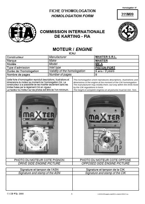
Homologation N°311M09FICHE D’HOMOLOGATION HOMOLOGATION FORMCOMMISSION INTERNATIONALEDE KARTING - FIAMOTEUR / ENGINEICAJConstructeur Manufacturer MAXTER S.R.L. Marque Make MAXTER ModèleModel MX-AType d’admissionInlet typePISTON PORT Durée de l’homologation Validity of the homologation 9 ans / 9 years Nombre de pagesNumber of pages9Cette fiche d’homologation reproduit descriptions, illustrations et dimensions du moteur au moment de l’homologation CIK. Le constructeur a la possibilité de les modifier seulement dans les limites fixées par le règlement CIK en vigueur.La hauteur du moteur sur les photos doit être de 7cm minimum.This homologation sheet reproduces descriptions, illustrations and dimensions of the engine at the moment of the CIK homologation. The manufacturer may modify them, but only within the limits fixed by the CIK regulations in force.The height of complete engines on all pictures must be min. 7cm.PHOTO DU MOTEUR COTE PIGNON PHOTO DU MOTEUR COTE OPPOSE DRIVE SIDE ENGINE PICTUREOPPOSED SIDE ENGINE PICTURESignature et tampon de l’ASN Signature et tampon de la CIK Signature and stamp of the ASNSignature and stamp of the CIKHomologation N°311M09 INFORMATIONS TECHNIQUES TECHNICAL INFORMATIONSA CARACTERISTIQUES A CARACTERISTICTSTolérances Volume du cylindre Cylinder volume 99.25 CM3< 100 cc Alésage d’origine Original Bore 49.95 MMAlésage théor. max. Theoritical max. bore 50.13 MMCourse Stroke 50.65 MMSystème de refroidissement Cooling system AIR COOLEDNombre de systèmes decarburationNumber of carburation systems 1Nombre de canaux de transfert, cylindre/carter Number of transfer ducts in the cylinder4 / 2Nombre de lumières / canauxd’échappementNumber of exhaust ports / ducts 2Forme de la chambre de combustion Shape of the combustionchamberSPHERICAL WITHSQUISHLongueur (entre-axe) de la bielle Lenght between the axes of theconnecting rod100 MM±0.1mm Poids de la bielle Weight of the connecting rod 103 GR minimum Poids du vilebrequin Weight of the crankshaft 1.634 GR minimum Volume de la chambre decombustionVolume of combustion chamber 4.83 CM3minimum Nombre de segments de piston Number of piston ringsModifications autorisées selon Règlement Technique.Seules les dimensions et cotes qui ne peuvent pas être modifiées doivent obligatoirement figurer sur la fiched’homologation.Modification allowed according to Technical Regulation.Only the dimensions and readings which may not been changed must obligatorily been mentioned on the homologation form.B ANGLES D’OUVERTURE B OPENING ANGLESDe l’admission Inlet 160.2°MaximumDe l’échappement Exhaust 172.2°MaximumC MATERIAU C MATERIALCylindre Cylinder AL – SI 9Culasse Cylinderhead AL – SI 9Carter Sump AL – SI 9Bielle Connecting rod 16 N CR M 5Homologation N°311M09DESSIN DU DEVELOPPEMENT DU CYLINDREDRAWING OF THE CYLINDER DEVELOPMENTSe référer à l'exemple de calcul donné à la page 6 où D représente le diamètre théorétique max. Indiquer sur le dessin:Bmin = épaisseur minimum de la division entre les lumières d'admission (s'il y en a une).A1/A2 = Largeur maximum de l'admission mesurée à la corde.Emin = épaisseur minimum de la division entre les lumières d'échappement (s'il y en a une).C1/C2 = largeur maximum de l'échappement mesurée à la corde.Refer to the calculation model shown on page 6 where D is the original theoretical max. diameter. Show on the drawing:Bmin = minimum thickness of the inlet rib (if existing). A1/A2 = max. inlet width-chordal width.Emin = minimum thickness of exhaust rib (if existing). C1/C2 = max exhaust width-chordal width.DESSIN DU PIED DUCYLINDREDRAWING OF THE CYLINDER BASEVUE EN SECTION DUCYLINDRECYLINDER SECTIONVIEWHomologation N°311M09DESSIN DE LA CULASSE ET DE LA CHAMBREDE COMBUSTIONDRAWING OF THE CYLINDER HEAD AND THECOMBUSTION CHAMBERDESSIN DU VILEBREQUINDRAWING OF THE CRANKSHAFTDESSIN INTERIEURDU CARTERDRAWING OF THE INTERIOR SUMPPHOTO DE L’ARRIEREDU MOTEURPHOTO OF THE BACKOF THE ENGINEPHOTO DE L’AVANTDU MOTEURPHOTO OF THE ENGINE FRONTPHOTO DU MOTEUR PARTIE SUPEREIUREPHOTO OF THE ENGINE TAKEN FROM ABOVEPHOTO DU MOTEUR PARTIE INFERIEUREPHOTO OF THE ENGINE TAKEN FROM BELOWPHOTO DU PIED DUCYLINDREPHOTO OF THE BASE OF THE CYLINDERPHOTO DE LA CHAMBRE DE COMBUSTIONPHOTO OF THE COMBUSTION CHAMBERPHOTO DU CARTER ( FACE DE JOINT ) PHOTO OF THE SUMP ( GASKET FACE ) PHOTO D’UNE PARTIE INTERIEURE DU CARTERPHOTO OF A PART OF THE SUMP’SINTERIORHomologation N° 311M09Homologation N° 311M09Homologation N°311M09POSITION DU CARBURATEUR CARBURETOR LOCATIONLa distance de 91mm de l'axe du cylindre peut compendre une éventuelle entretoise placée avant le carburateur.91mm distance from the cylinder center line may include an eventual spacer located before the carburetor.。
ABB功能码中文资料

第一章功能码概述一、专用术语·功能码(Function Code):Symphony 系统提供了一系列完成不同功能的软件模块,并对每个软件模块指定一个代码,称为功能码。
·功能码数据库(Function Code Library):指功能码的集合,它存放在各种控制器的只读存储器(ROM)中。
每一种控制器的ROM中只存放该控制器组态所能使用的功能码。
·功能块(Function Block):当选用一个功能码时,必需指定一个块号(即块地址),该选定了的功能码称为功能块。
·规格参数(Specification)指功能码的输入参数。
规格参数有两种类型:-地址类的规格参数;-内部规格参数。
·功能码组态:根据过程控制方案,选择一些合适的功能码,将其互相连接,并对每个功能码指定其具体功能,将其存放到控制器的NVRAM中的过程称为功能码组态。
二、功能块SYMPHONY系统是由一套运用微处理器执行控制功能的模件组成的。
通过组态“功能块”,在主模件上实现控制功能的选择和相互配合。
一个功能块仅仅是一个输入或输出,或者是一个输入或输出的操作。
这些功能块是一般的软件控制算法,可以用它们来执行在其它类型系统需要专门硬件完成的指定任务。
有四种类型功能块:1.执行块2.系统常数块3.输入/输出块4.用户组态块执行块包含影响模件综合操作的一些参数。
系统常数块例如是0、1和100.0等这样的一些数字量参数和模拟量参数。
当用这些通常所用的值进行模件组态时,只要可能就应尽量使用这些系统常数块。
它们要求的内存比手动设定常数块少。
输入/输出块是一些固定块地址,它们对应于一个模件通过端子单元和现场布线的现场输入和输出。
用户组态块不是预先指定的块,而是由用户设定,以执行用户特需功能从而实现控制逻辑。
每个SYMPHONY主模件都有一套供选择的预先定义的块地址。
功能块的最基本类型是输入和输出。
每个输入或输出都在该模件的固件中被赋予一个块号。
SD100-11-31-221中文资料
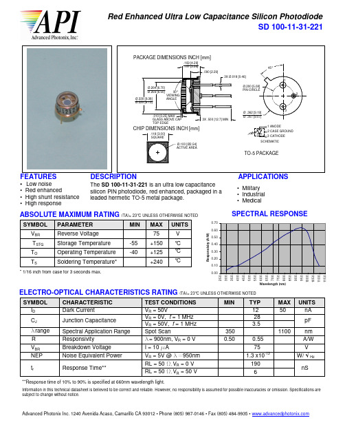
350 0.50
**Response time of 10% to 90% is specified at 660nm wavelength light.
Information in this technical datasheet is believed to be correct and reliable. However, no responsibility is assumed for possible inaccuracies or omission. Specifications are subject to change without notice.
500
550
600
650
700
750
800
850
900
950
元器件交易网
Red Enhanced Ultra Low Capacitance Silicon Photodiode SD 100-11-31-221
PACKAGE DIMENSIONSINCH [mm] INCH [mm] PACKAGE DIMENSIONS
.169 [4.29] .157 [3.99] .090 [2.29] 3X Ø.018 [0.46] 1 Ø.264 [6.70] Ø.256 [6.50] Ø.330 [8.38] Ø.320 [8.13] Ø.200 [5.08] PIN CIRCLE 2 45°
Responsivity (A/W) 0.70 0.60 0.50 0.40 0.30 0.20 0.10 0.00
SPECTRAL RESPONSE
V ° C ° C ° C
* 1/16 inch from case for 3 seconds max.
MIKE11中文教程

1 - RR /
1. 2. 3. 4.
MIKE 11 RR
30-60 CPU
1000-2000
10 25 mm 50 250mm Lmax 0.1*Umax 01 500 1000 hr 01 01 01 3 48 hr 500 5000 hr
9 9
3
MIKE 11 RR
MIKE 11 RR
MIKE 11 RR 1
1 MIKE 11 RR
1
MIKE11
RR
1
MIKE11
HD
1960’s MIKE 11 RR
1 - MIKE 11 RR
2
MIKE 11 RR
1
MIKE 11 RR 2
2 - MIKE 11 RR
3
MIKE11 RR
1
2
Umax
Lmax CQOF CKIF TOF TIF TG CK12 CKBF
北京
目录
1 MIKE 11 RR............................................................................................................................... 1 2 MIKE 11 HD 建模所需信息 ..................................................................................................... 5 3 MIKE 11 HD 结构 ..................................................................................................................... 6 4 河网文件生成方法(.nwk11 )............................................................................................... 6 5 断面文件生成方法(.xns11 ) .............................................................................................. 10 6 时间序列文件生成方法(.dfs0)........................................................................................... 13 7 边界文件生成方法(.bnd11) ............................................................................................... 14 8 参数文件设置方法(.HD11)................................................................................................ 16 9 模拟文件设置方法(.sim11) ................................................................................................ 17 10 结果查看与分析(MIKE VIEW) ....................................................................................... 20 11 MIKE HD 与 NAM 模型耦合 ............................................................................................... 24 12 水工建筑物 ............................................................................................................................ 25 13 可控水工建筑物 .................................................................................................................... 25 14 MIKE 11 AD .......................................................................................................................... 29 附录一 MIKE11 断面导入文件格式 ........................................................................................... 34 附录二 MIKE11 模拟文件设置说明 ........................................................................................... 35 附录三 MIKE11 常见错误及解决方法 ....................................................................................... 42
AC111标准翻译中文版
高压气体用储罐及压力容器制造的设备、技术、检验标准气体技术标准委员会审议和表决通过日期:2015年12月18日产业通商资源部审批通过日期:2016年1月8日目 录1.一般规定‐‐‐‐‐‐‐‐‐‐‐‐‐‐‐‐‐‐‐‐‐‐‐‐‐‐‐‐‐‐‐‐‐‐‐‐‐‐‐‐‐‐‐‐‐‐‐‐‐‐‐‐‐‐‐‐‐‐‐‐‐‐‐‐‐‐‐‐‐‐‐‐‐‐‐‐‐‐‐‐‐‐‐‐‐‐‐‐‐‐‐‐11.1适用范围‐‐‐‐‐‐‐‐‐‐‐‐‐‐‐‐‐‐‐‐‐‐‐‐‐‐‐‐‐‐‐‐‐‐‐‐‐‐‐‐‐‐‐‐‐‐‐‐‐‐‐‐‐‐‐‐‐‐‐‐‐‐‐‐‐‐‐‐‐‐‐‐‐‐‐‐‐‐‐‐‐‐‐‐‐‐‐11.2 标准的效力‐‐‐‐‐‐‐‐‐‐‐‐‐‐‐‐‐‐‐‐‐‐‐‐‐‐‐‐‐‐‐‐‐‐‐‐‐‐‐‐‐‐‐‐‐‐‐‐‐‐‐‐‐‐‐‐‐‐‐‐‐‐‐‐‐‐‐‐‐‐‐‐‐‐‐‐‐‐‐‐‐‐‐11.3 其他标准的认可‐‐‐‐‐‐‐‐‐‐‐‐‐‐‐‐‐‐‐‐‐‐‐‐‐‐‐‐‐‐‐‐‐‐‐‐‐‐‐‐‐‐‐‐‐‐‐‐‐‐‐‐‐‐‐‐‐‐‐‐‐‐‐‐‐‐‐‐‐‐‐‐‐‐‐‐‐11.3.1新技术产品的检验标准‐‐‐‐‐‐‐‐‐‐‐‐‐‐‐‐‐‐‐‐‐‐‐‐‐‐‐‐‐‐‐‐‐‐‐‐‐‐‐‐‐‐‐‐‐‐‐‐‐‐‐‐‐‐‐‐‐‐‐‐‐‐‐11.3.2 外国压力容器等制造登记标准‐‐‐‐‐‐‐‐‐‐‐‐‐‐‐‐‐‐‐‐‐‐‐‐‐‐‐‐‐‐‐‐‐‐‐‐‐‐‐‐‐‐‐‐‐‐‐‐‐‐‐‐2 1.4术语‐‐‐‐‐‐‐‐‐‐‐‐‐‐‐‐‐‐‐‐‐‐‐‐‐‐‐‐‐‐‐‐‐‐‐‐‐‐‐‐‐‐‐‐‐‐‐‐‐‐‐‐‐‐‐‐‐‐‐‐‐‐‐‐‐‐‐‐‐‐‐‐‐‐‐‐‐‐‐‐‐‐‐‐‐‐‐‐‐‐‐‐‐‐‐21.5标准的‐‐‐‐‐‐‐‐‐‐‐‐‐‐‐‐‐‐‐‐‐‐‐‐‐‐‐‐‐‐‐‐‐‐‐‐‐‐‐‐‐‐‐‐‐‐‐‐‐‐‐‐‐‐‐‐‐‐‐‐‐‐‐‐‐‐‐‐‐‐‐‐‐‐‐‐‐‐‐‐‐‐‐‐‐‐‐‐‐‐‐‐32.制造设备标准‐‐‐‐‐‐‐‐‐‐‐‐‐‐‐‐‐‐‐‐‐‐‐‐‐‐‐‐‐‐‐‐‐‐‐‐‐‐‐‐‐‐‐‐‐‐‐‐‐‐‐‐‐‐‐‐‐‐‐‐‐‐‐‐‐‐‐‐‐‐‐‐‐‐‐‐‐‐‐‐‐‐‐‐‐‐32.1制造设备‐‐‐‐‐‐‐‐‐‐‐‐‐‐‐‐‐‐‐‐‐‐‐‐‐‐‐‐‐‐‐‐‐‐‐‐‐‐‐‐‐‐‐‐‐‐‐‐‐‐‐‐‐‐‐‐‐‐‐‐‐‐‐‐‐‐‐‐‐‐‐‐‐‐‐‐‐‐‐‐‐‐‐‐‐‐‐‐32.2检验设备‐‐‐‐‐‐‐‐‐‐‐‐‐‐‐‐‐‐‐‐‐‐‐‐‐‐‐‐‐‐‐‐‐‐‐‐‐‐‐‐‐‐‐‐‐‐‐‐‐‐‐‐‐‐‐‐‐‐‐‐‐‐‐‐‐‐‐‐‐‐‐‐‐‐‐‐‐‐‐‐‐‐‐‐‐‐‐‐43.制造技术标准‐‐‐‐‐‐‐‐‐‐‐‐‐‐‐‐‐‐‐‐‐‐‐‐‐‐‐‐‐‐‐‐‐‐‐‐‐‐‐‐‐‐‐‐‐‐‐‐‐‐‐‐‐‐‐‐‐‐‐‐‐‐‐‐‐‐‐‐‐‐‐‐‐‐‐‐‐‐‐‐‐‐‐‐‐‐43.1设计‐‐‐‐‐‐‐‐‐‐‐‐‐‐‐‐‐‐‐‐‐‐‐‐‐‐‐‐‐‐‐‐‐‐‐‐‐‐‐‐‐‐‐‐‐‐‐‐‐‐‐‐‐‐‐‐‐‐‐‐‐‐‐‐‐‐‐‐‐‐‐‐‐‐‐‐‐‐‐‐‐‐‐‐‐‐‐‐‐‐‐‐‐‐43.2材料‐‐‐‐‐‐‐‐‐‐‐‐‐‐‐‐‐‐‐‐‐‐‐‐‐‐‐‐‐‐‐‐‐‐‐‐‐‐‐‐‐‐‐‐‐‐‐‐‐‐‐‐‐‐‐‐‐‐‐‐‐‐‐‐‐‐‐‐‐‐‐‐‐‐‐‐‐‐‐‐‐‐‐‐‐‐‐‐‐‐‐‐‐‐‐43.3厚度‐‐‐‐‐‐‐‐‐‐‐‐‐‐‐‐‐‐‐‐‐‐‐‐‐‐‐‐‐‐‐‐‐‐‐‐‐‐‐‐‐‐‐‐‐‐‐‐‐‐‐‐‐‐‐‐‐‐‐‐‐‐‐‐‐‐‐‐‐‐‐‐‐‐‐‐‐‐‐‐‐‐‐‐‐‐‐‐‐‐‐‐‐103.3.1 接管之外部位的最低厚度‐‐‐‐‐‐‐‐‐‐‐‐‐‐‐‐‐‐‐‐‐‐‐‐‐‐‐‐‐‐‐‐‐‐‐‐‐‐‐‐‐‐‐‐‐‐‐‐‐‐‐‐‐‐‐‐‐113.3.2 接管的最低厚度‐‐‐‐‐‐‐‐‐‐‐‐‐‐‐‐‐‐‐‐‐‐‐‐‐‐‐‐‐‐‐‐‐‐‐‐‐‐‐‐‐‐‐‐‐‐‐‐‐‐‐‐‐‐‐‐‐‐‐‐‐‐‐‐‐‐‐‐‐‐27 3.4结构及尺寸‐‐‐‐‐‐‐‐‐‐‐‐‐‐‐‐‐‐‐‐‐‐‐‐‐‐‐‐‐‐‐‐‐‐‐‐‐‐‐‐‐‐‐‐‐‐‐‐‐‐‐‐‐‐‐‐‐‐‐‐‐‐‐‐‐‐‐‐‐‐‐‐‐‐‐‐‐‐‐‐‐‐‐‐‐‐‐293.4.1 法兰规格‐‐‐‐‐‐‐‐‐‐‐‐‐‐‐‐‐‐‐‐‐‐‐‐‐‐‐‐‐‐‐‐‐‐‐‐‐‐‐‐‐‐‐‐‐‐‐‐‐‐‐‐‐‐‐‐‐‐‐‐‐‐‐‐‐‐‐‐‐‐‐‐‐‐‐‐‐‐‐‐‐‐293.4.2 筒体的真圆度‐‐‐‐‐‐‐‐‐‐‐‐‐‐‐‐‐‐‐‐‐‐‐‐‐‐‐‐‐‐‐‐‐‐‐‐‐‐‐‐‐‐‐‐‐‐‐‐‐‐‐‐‐‐‐‐‐‐‐‐‐‐‐‐‐‐‐‐‐‐‐‐‐‐‐‐293.4.3圆锥形筒体的形状‐‐‐‐‐‐‐‐‐‐‐‐‐‐‐‐‐‐‐‐‐‐‐‐‐‐‐‐‐‐‐‐‐‐‐‐‐‐‐‐‐‐‐‐‐‐‐‐‐‐‐‐‐‐‐‐‐‐‐‐‐‐‐‐‐‐‐‐‐‐313.4.4 封头的形状‐‐‐‐‐‐‐‐‐‐‐‐‐‐‐‐‐‐‐‐‐‐‐‐‐‐‐‐‐‐‐‐‐‐‐‐‐‐‐‐‐‐‐‐‐‐‐‐‐‐‐‐‐‐‐‐‐‐‐‐‐‐‐‐‐‐‐‐‐‐‐‐‐‐‐‐‐‐‐313.4.5 压力容器等上的开孔‐‐‐‐‐‐‐‐‐‐‐‐‐‐‐‐‐‐‐‐‐‐‐‐‐‐‐‐‐‐‐‐‐‐‐‐‐‐‐‐‐‐‐‐‐‐‐‐‐‐‐‐‐‐‐‐‐‐‐‐‐‐‐‐‐‐333.5加工 ‐‐‐‐‐‐‐‐‐‐‐‐‐‐‐‐‐‐‐‐‐‐‐‐‐‐‐‐‐‐‐‐‐‐‐‐‐‐‐‐‐‐‐‐‐‐‐‐‐‐‐‐‐‐‐‐‐‐‐‐‐‐‐‐‐‐‐‐‐‐‐‐‐‐‐‐‐‐‐‐‐‐‐‐‐‐‐‐‐‐‐333.5.1材料的切割、成型及修整‐‐‐‐‐‐‐‐‐‐‐‐‐‐‐‐‐‐‐‐‐‐‐‐‐‐‐‐‐‐‐‐‐‐‐‐‐‐‐‐‐‐‐‐‐‐‐‐‐‐‐‐‐‐‐‐‐‐‐‐333.5.2 管板上接管的安装方法‐‐‐‐‐‐‐‐‐‐‐‐‐‐‐‐‐‐‐‐‐‐‐‐‐‐‐‐‐‐‐‐‐‐‐‐‐‐‐‐‐‐‐‐‐‐‐‐‐‐‐‐‐‐‐‐‐‐‐‐‐‐343.5.3 防漏焊接‐‐‐‐‐‐‐‐‐‐‐‐‐‐‐‐‐‐‐‐‐‐‐‐‐‐‐‐‐‐‐‐‐‐‐‐‐‐‐‐‐‐‐‐‐‐‐‐‐‐‐‐‐‐‐‐‐‐‐‐‐‐‐‐‐‐‐‐‐‐‐‐‐‐‐‐‐‐‐‐‐‐353.5.4直管的弯曲加工‐‐‐‐‐‐‐‐‐‐‐‐‐‐‐‐‐‐‐‐‐‐‐‐‐‐‐‐‐‐‐‐‐‐‐‐‐‐‐‐‐‐‐‐‐‐‐‐‐‐‐‐‐‐‐‐‐‐‐‐‐‐‐‐‐‐‐‐‐‐‐‐‐‐353.5.5 支座Stay安装‐‐‐‐‐‐‐‐‐‐‐‐‐‐‐‐‐‐‐‐‐‐‐‐‐‐‐‐‐‐‐‐‐‐‐‐‐‐‐‐‐‐‐‐‐‐‐‐‐‐‐‐‐‐‐‐‐‐‐‐‐‐‐‐‐‐‐‐‐‐‐‐‐‐‐‐353.5.6 伸缩接头‐‐‐‐‐‐‐‐‐‐‐‐‐‐‐‐‐‐‐‐‐‐‐‐‐‐‐‐‐‐‐‐‐‐‐‐‐‐‐‐‐‐‐‐‐‐‐‐‐‐‐‐‐‐‐‐‐‐‐‐‐‐‐‐‐‐‐‐‐‐‐‐‐‐‐‐‐‐‐‐‐‐363.5.7 开孔的补强‐‐‐‐‐‐‐‐‐‐‐‐‐‐‐‐‐‐‐‐‐‐‐‐‐‐‐‐‐‐‐‐‐‐‐‐‐‐‐‐‐‐‐‐‐‐‐‐‐‐‐‐‐‐‐‐‐‐‐‐‐‐‐‐‐‐‐‐‐‐‐‐‐‐‐‐‐‐‐383.5.8 补强圈‐‐‐‐‐‐‐‐‐‐‐‐‐‐‐‐‐‐‐‐‐‐‐‐‐‐‐‐‐‐‐‐‐‐‐‐‐‐‐‐‐‐‐‐‐‐‐‐‐‐‐‐‐‐‐‐‐‐‐‐‐‐‐‐‐‐‐‐‐‐‐‐‐‐‐‐‐‐‐‐‐‐‐‐‐‐43 3.6 焊接‐‐‐‐‐‐‐‐‐‐‐‐‐‐‐‐‐‐‐‐‐‐‐‐‐‐‐‐‐‐‐‐‐‐‐‐‐‐‐‐‐‐‐‐‐‐‐‐‐‐‐‐‐‐‐‐‐‐‐‐‐‐‐‐‐‐‐‐‐‐‐‐‐‐‐‐‐‐‐‐‐‐‐‐‐‐‐‐‐‐‐‐‐‐‐‐‐46 3.6.1焊接接头的分类‐‐‐‐‐‐‐‐‐‐‐‐‐‐‐‐‐‐‐‐‐‐‐‐‐‐‐‐‐‐‐‐‐‐‐‐‐‐‐‐‐‐‐‐‐‐‐‐‐‐‐‐‐‐‐‐‐‐‐‐‐‐‐‐‐‐‐‐‐‐‐‐‐‐‐‐46 3.6.2 焊接种类的限制‐‐‐‐‐‐‐‐‐‐‐‐‐‐‐‐‐‐‐‐‐‐‐‐‐‐‐‐‐‐‐‐‐‐‐‐‐‐‐‐‐‐‐‐‐‐‐‐‐‐‐‐‐‐‐‐‐‐‐‐‐‐‐‐‐‐‐‐‐‐‐‐‐‐‐47 3.6.3 焊缝的效率‐‐‐‐‐‐‐‐‐‐‐‐‐‐‐‐‐‐‐‐‐‐‐‐‐‐‐‐‐‐‐‐‐‐‐‐‐‐‐‐‐‐‐‐‐‐‐‐‐‐‐‐‐‐‐‐‐‐‐‐‐‐‐‐‐‐‐‐‐‐‐‐‐‐‐‐‐‐‐‐‐48 3.6.4 焊接部位强度等‐‐‐‐‐‐‐‐‐‐‐‐‐‐‐‐‐‐‐‐‐‐‐‐‐‐‐‐‐‐‐‐‐‐‐‐‐‐‐‐‐‐‐‐‐‐‐‐‐‐‐‐‐‐‐‐‐‐‐‐‐‐‐‐‐‐‐‐‐‐‐‐‐‐‐49 3.6.5 对焊‐‐‐‐‐‐‐‐‐‐‐‐‐‐‐‐‐‐‐‐‐‐‐‐‐‐‐‐‐‐‐‐‐‐‐‐‐‐‐‐‐‐‐‐‐‐‐‐‐‐‐‐‐‐‐‐‐‐‐‐‐‐‐‐‐‐‐‐‐‐‐‐‐‐‐‐‐‐‐‐‐‐‐‐‐‐‐‐‐‐‐49 3.6.6 双面全焊透角焊‐‐‐‐‐‐‐‐‐‐‐‐‐‐‐‐‐‐‐‐‐‐‐‐‐‐‐‐‐‐‐‐‐‐‐‐‐‐‐‐‐‐‐‐‐‐‐‐‐‐‐‐‐‐‐‐‐‐‐‐‐‐‐‐‐‐‐‐‐‐‐‐‐‐51 3.6.7封头和筒板焊接‐‐‐‐‐‐‐‐‐‐‐‐‐‐‐‐‐‐‐‐‐‐‐‐‐‐‐‐‐‐‐‐‐‐‐‐‐‐‐‐‐‐‐‐‐‐‐‐‐‐‐‐‐‐‐‐‐‐‐‐‐‐‐‐‐‐‐‐‐‐‐‐‐‐‐51 3.6.8筒板和平板等的焊接‐‐‐‐‐‐‐‐‐‐‐‐‐‐‐‐‐‐‐‐‐‐‐‐‐‐‐‐‐‐‐‐‐‐‐‐‐‐‐‐‐‐‐‐‐‐‐‐‐‐‐‐‐‐‐‐‐‐‐‐‐‐‐‐‐‐‐‐‐52 3.6.9 喷嘴、补强材料等的焊接‐‐‐‐‐‐‐‐‐‐‐‐‐‐‐‐‐‐‐‐‐‐‐‐‐‐‐‐‐‐‐‐‐‐‐‐‐‐‐‐‐‐‐‐‐‐‐‐‐‐‐‐‐‐‐‐‐‐‐‐‐‐‐523.6.10 补强圈的焊接‐‐‐‐‐‐‐‐‐‐‐‐‐‐‐‐‐‐‐‐‐‐‐‐‐‐‐‐‐‐‐‐‐‐‐‐‐‐‐‐‐‐‐‐‐‐‐‐‐‐‐‐‐‐‐‐‐‐‐‐‐‐‐‐‐‐‐‐‐‐‐‐‐‐‐‐533.6.11 夹套焊接‐‐‐‐‐‐‐‐‐‐‐‐‐‐‐‐‐‐‐‐‐‐‐‐‐‐‐‐‐‐‐‐‐‐‐‐‐‐‐‐‐‐‐‐‐‐‐‐‐‐‐‐‐‐‐‐‐‐‐‐‐‐‐‐‐‐‐‐‐‐‐‐‐‐‐‐‐‐‐‐‐‐‐533.6.12 支座Stay焊接‐‐‐‐‐‐‐‐‐‐‐‐‐‐‐‐‐‐‐‐‐‐‐‐‐‐‐‐‐‐‐‐‐‐‐‐‐‐‐‐‐‐‐‐‐‐‐‐‐‐‐‐‐‐‐‐‐‐‐‐‐‐‐‐‐‐‐‐‐‐‐‐‐‐‐‐533.6.13 焊接部位的修整‐‐‐‐‐‐‐‐‐‐‐‐‐‐‐‐‐‐‐‐‐‐‐‐‐‐‐‐‐‐‐‐‐‐‐‐‐‐‐‐‐‐‐‐‐‐‐‐‐‐‐‐‐‐‐‐‐‐‐‐‐‐‐‐‐‐‐‐‐‐‐‐‐543.6.14 焊接条件‐‐‐‐‐‐‐‐‐‐‐‐‐‐‐‐‐‐‐‐‐‐‐‐‐‐‐‐‐‐‐‐‐‐‐‐‐‐‐‐‐‐‐‐‐‐‐‐‐‐‐‐‐‐‐‐‐‐‐‐‐‐‐‐‐‐‐‐‐‐‐‐‐‐‐‐‐‐‐‐‐‐‐543.7热处理‐‐‐‐‐‐‐‐‐‐‐‐‐‐‐‐‐‐‐‐‐‐‐‐‐‐‐‐‐‐‐‐‐‐‐‐‐‐‐‐‐‐‐‐‐‐‐‐‐‐‐‐‐‐‐‐‐‐‐‐‐‐‐‐‐‐‐‐‐‐‐‐‐‐‐‐‐‐‐‐‐‐‐‐‐‐‐‐‐‐‐‐‐‐‐563.7.1成型后的热处理 ‐‐‐‐‐‐‐‐‐‐‐‐‐‐‐‐‐‐‐‐‐‐‐‐‐‐‐‐‐‐‐‐‐‐‐‐‐‐‐‐‐‐‐‐‐‐‐‐‐‐‐‐‐‐‐‐‐‐‐‐‐‐‐‐‐‐‐‐‐‐‐‐‐‐‐563.7.2 消除焊接应力‐‐‐‐‐‐‐‐‐‐‐‐‐‐‐‐‐‐‐‐‐‐‐‐‐‐‐‐‐‐‐‐‐‐‐‐‐‐‐‐‐‐‐‐‐‐‐‐‐‐‐‐‐‐‐‐‐‐‐‐‐‐‐‐‐‐‐‐‐‐‐‐‐‐‐‐‐‐573.8 性能(无内容)‐‐‐‐‐‐‐‐‐‐‐‐‐‐‐‐‐‐‐‐‐‐‐‐‐‐‐‐‐‐‐‐‐‐‐‐‐‐‐‐‐‐‐‐‐‐‐‐‐‐‐‐‐‐‐‐‐‐‐‐‐‐‐‐‐‐‐‐‐‐‐‐‐‐‐‐‐‐‐‐‐593.9 喷涂(无内容)‐‐‐‐‐‐‐‐‐‐‐‐‐‐‐‐‐‐‐‐‐‐‐‐‐‐‐‐‐‐‐‐‐‐‐‐‐‐‐‐‐‐‐‐‐‐‐‐‐‐‐‐‐‐‐‐‐‐‐‐‐‐‐‐‐‐‐‐‐‐‐‐‐‐‐‐‐‐‐‐593.10 安全装置的安装(无内容)‐‐‐‐‐‐‐‐‐‐‐‐‐‐‐‐‐‐‐‐‐‐‐‐‐‐‐‐‐‐‐‐‐‐‐‐‐‐‐‐‐‐‐‐‐‐‐‐‐‐‐‐‐‐‐‐‐‐‐‐‐‐‐593.11附件的安装(无内容)‐‐‐‐‐‐‐‐‐‐‐‐‐‐‐‐‐‐‐‐‐‐‐‐‐‐‐‐‐‐‐‐‐‐‐‐‐‐‐‐‐‐‐‐‐‐‐‐‐‐‐‐‐‐‐‐‐‐‐‐‐‐‐‐‐‐‐‐‐‐593.12 涂色及标记‐‐‐‐‐‐‐‐‐‐‐‐‐‐‐‐‐‐‐‐‐‐‐‐‐‐‐‐‐‐‐‐‐‐‐‐‐‐‐‐‐‐‐‐‐‐‐‐‐‐‐‐‐‐‐‐‐‐‐‐‐‐‐‐‐‐‐‐‐‐‐‐‐‐‐‐‐‐‐‐‐‐‐‐‐593.12.1 外面涂色(无内容)‐‐‐‐‐‐‐‐‐‐‐‐‐‐‐‐‐‐‐‐‐‐‐‐‐‐‐‐‐‐‐‐‐‐‐‐‐‐‐‐‐‐‐‐‐‐‐‐‐‐‐‐‐‐‐‐‐‐‐‐‐‐‐‐‐593.12.2 气体种类的标记(无内容)‐‐‐‐‐‐‐‐‐‐‐‐‐‐‐‐‐‐‐‐‐‐‐‐‐‐‐‐‐‐‐‐‐‐‐‐‐‐‐‐‐‐‐‐‐‐‐‐‐‐‐‐‐‐‐‐593.12.3 产品标识‐‐‐‐‐‐‐‐‐‐‐‐‐‐‐‐‐‐‐‐‐‐‐‐‐‐‐‐‐‐‐‐‐‐‐‐‐‐‐‐‐‐‐‐‐‐‐‐‐‐‐‐‐‐‐‐‐‐‐‐‐‐‐‐‐‐‐‐‐‐‐‐‐‐‐‐‐‐‐‐‐593.12.4 合格标识‐‐‐‐‐‐‐‐‐‐‐‐‐‐‐‐‐‐‐‐‐‐‐‐‐‐‐‐‐‐‐‐‐‐‐‐‐‐‐‐‐‐‐‐‐‐‐‐‐‐‐‐‐‐‐‐‐‐‐‐‐‐‐‐‐‐‐‐‐‐‐‐‐‐‐‐‐‐‐‐‐604.检验标准 ‐‐‐‐‐‐‐‐‐‐‐‐‐‐‐‐‐‐‐‐‐‐‐‐‐‐‐‐‐‐‐‐‐‐‐‐‐‐‐‐‐‐‐‐‐‐‐‐‐‐‐‐‐‐‐‐‐‐‐‐‐‐‐‐‐‐‐‐‐‐‐‐‐‐‐‐‐‐‐‐‐‐‐‐‐‐‐‐‐‐604.1 检验种类‐‐‐‐‐‐‐‐‐‐‐‐‐‐‐‐‐‐‐‐‐‐‐‐‐‐‐‐‐‐‐‐‐‐‐‐‐‐‐‐‐‐‐‐‐‐‐‐‐‐‐‐‐‐‐‐‐‐‐‐‐‐‐‐‐‐‐‐‐‐‐‐‐‐‐‐‐‐‐‐‐‐‐‐‐‐‐‐‐‐604.1.1关于制造设备的检验‐‐‐‐‐‐‐‐‐‐‐‐‐‐‐‐‐‐‐‐‐‐‐‐‐‐‐‐‐‐‐‐‐‐‐‐‐‐‐‐‐‐‐‐‐‐‐‐‐‐‐‐‐‐‐‐‐‐‐‐‐‐‐‐‐‐‐‐604.1.2 关于产品检验‐‐‐‐‐‐‐‐‐‐‐‐‐‐‐‐‐‐‐‐‐‐‐‐‐‐‐‐‐‐‐‐‐‐‐‐‐‐‐‐‐‐‐‐‐‐‐‐‐‐‐‐‐‐‐‐‐‐‐‐‐‐‐‐‐‐‐‐‐‐‐‐‐‐‐‐604.2 工艺检验对象的审查‐‐‐‐‐‐‐‐‐‐‐‐‐‐‐‐‐‐‐‐‐‐‐‐‐‐‐‐‐‐‐‐‐‐‐‐‐‐‐‐‐‐‐‐‐‐‐‐‐‐‐‐‐‐‐‐‐‐‐‐‐‐‐‐‐‐‐‐‐‐‐‐‐‐61 4.2.1审查的申请‐‐‐‐‐‐‐‐‐‐‐‐‐‐‐‐‐‐‐‐‐‐‐‐‐‐‐‐‐‐‐‐‐‐‐‐‐‐‐‐‐‐‐‐‐‐‐‐‐‐‐‐‐‐‐‐‐‐‐‐‐‐‐‐‐‐‐‐‐‐‐‐‐‐‐‐‐‐‐‐‐614.2.2 审查方法‐‐‐‐‐‐‐‐‐‐‐‐‐‐‐‐‐‐‐‐‐‐‐‐‐‐‐‐‐‐‐‐‐‐‐‐‐‐‐‐‐‐‐‐‐‐‐‐‐‐‐‐‐‐‐‐‐‐‐‐‐‐‐‐‐‐‐‐‐‐‐‐‐‐‐‐‐‐‐‐‐‐‐614.2.3评定委员会‐‐‐‐‐‐‐‐‐‐‐‐‐‐‐‐‐‐‐‐‐‐‐‐‐‐‐‐‐‐‐‐‐‐‐‐‐‐‐‐‐‐‐‐‐‐‐‐‐‐‐‐‐‐‐‐‐‐‐‐‐‐‐‐‐‐‐‐‐‐‐‐‐‐‐‐‐‐‐‐‐614.3 检验项目 ‐‐‐‐‐‐‐‐‐‐‐‐‐‐‐‐‐‐‐‐‐‐‐‐‐‐‐‐‐‐‐‐‐‐‐‐‐‐‐‐‐‐‐‐‐‐‐‐‐‐‐‐‐‐‐‐‐‐‐‐‐‐‐‐‐‐‐‐‐‐‐‐‐‐‐‐‐‐‐‐‐‐‐‐‐‐‐‐‐634.3.1 制造设备的检验‐‐‐‐‐‐‐‐‐‐‐‐‐‐‐‐‐‐‐‐‐‐‐‐‐‐‐‐‐‐‐‐‐‐‐‐‐‐‐‐‐‐‐‐‐‐‐‐‐‐‐‐‐‐‐‐‐‐‐‐‐‐‐‐‐‐‐‐‐‐‐‐‐‐‐634.3.2 产品的检验‐‐‐‐‐‐‐‐‐‐‐‐‐‐‐‐‐‐‐‐‐‐‐‐‐‐‐‐‐‐‐‐‐‐‐‐‐‐‐‐‐‐‐‐‐‐‐‐‐‐‐‐‐‐‐‐‐‐‐‐‐‐‐‐‐‐‐‐‐‐‐‐‐‐‐‐‐‐‐‐‐‐634.5 其他标准‐‐‐‐‐‐‐‐‐‐‐‐‐‐‐‐‐‐‐‐‐‐‐‐‐‐‐‐‐‐‐‐‐‐‐‐‐‐‐‐‐‐‐‐‐‐‐‐‐‐‐‐‐‐‐‐‐‐‐‐‐‐‐‐‐‐‐‐‐‐‐‐‐‐‐‐‐‐‐‐‐‐‐‐‐‐‐‐‐‐794.5.1 进口产品的检验(无内容)‐‐‐‐‐‐‐‐‐‐‐‐‐‐‐‐‐‐‐‐‐‐‐‐‐‐‐‐‐‐‐‐‐‐‐‐‐‐‐‐‐‐‐‐‐‐‐‐‐‐‐‐‐‐‐‐‐794.5.2 部分检验的省略‐‐‐‐‐‐‐‐‐‐‐‐‐‐‐‐‐‐‐‐‐‐‐‐‐‐‐‐‐‐‐‐‐‐‐‐‐‐‐‐‐‐‐‐‐‐‐‐‐‐‐‐‐‐‐‐‐‐‐‐‐‐‐‐‐‐‐‐‐‐‐‐‐794.5.3 不合格产品报废方法‐‐‐‐‐‐‐‐‐‐‐‐‐‐‐‐‐‐‐‐‐‐‐‐‐‐‐‐‐‐‐‐‐‐‐‐‐‐‐‐‐‐‐‐‐‐‐‐‐‐‐‐‐‐‐‐‐‐‐‐‐‐‐‐‐‐‐‐‐‐79附录A 铁板材质最大许用拉伸应力值‐‐‐‐‐‐‐‐‐‐‐‐‐‐‐‐‐‐‐‐‐‐‐‐‐‐‐‐‐‐‐‐‐‐‐‐‐‐‐‐‐‐‐‐‐‐‐‐‐‐‐80附录A 之2 非金属材料最大许用拉伸应力值‐‐‐‐‐‐‐‐‐‐‐‐‐‐‐‐‐‐‐‐‐‐‐‐‐‐‐‐‐‐‐‐‐‐‐‐‐‐‐‐101附录B ‐‐‐‐‐‐‐‐‐‐‐‐‐‐‐‐‐‐‐‐‐‐‐‐‐‐‐‐‐‐‐‐‐‐‐‐‐‐‐‐‐‐‐‐‐‐‐‐‐‐‐‐‐‐‐‐‐‐‐‐‐‐‐‐‐‐‐‐‐‐‐‐‐‐‐‐‐‐‐‐‐‐‐‐‐‐‐‐‐‐‐‐‐‐‐‐‐‐112附录C 母材种类对应的热处理温度‐‐‐‐‐‐‐‐‐‐‐‐‐‐‐‐‐‐‐‐‐‐‐‐‐‐‐‐‐‐‐‐‐‐‐‐‐‐‐‐‐‐‐‐‐‐‐‐‐‐‐‐‐‐‐‐‐‐122附录D 热处理温度降低的补正定数‐‐‐‐‐‐‐‐‐‐‐‐‐‐‐‐‐‐‐‐‐‐‐‐‐‐‐‐‐‐‐‐‐‐‐‐‐‐‐‐‐‐‐‐‐‐‐‐‐‐‐‐‐‐‐‐‐‐122附录E 母材的划分‐‐‐‐‐‐‐‐‐‐‐‐‐‐‐‐‐‐‐‐‐‐‐‐‐‐‐‐‐‐‐‐‐‐‐‐‐‐‐‐‐‐‐‐‐‐‐‐‐‐‐‐‐‐‐‐‐‐‐‐‐‐‐‐‐‐‐‐‐‐‐‐‐‐‐‐‐‐‐‐‐123附录F 手工电弧焊的划分‐‐‐‐‐‐‐‐‐‐‐‐‐‐‐‐‐‐‐‐‐‐‐‐‐‐‐‐‐‐‐‐‐‐‐‐‐‐‐‐‐‐‐‐‐‐‐‐‐‐‐‐‐‐‐‐‐‐‐‐‐‐‐‐‐‐‐‐‐‐‐128附录G 焊接线的划分‐‐‐‐‐‐‐‐‐‐‐‐‐‐‐‐‐‐‐‐‐‐‐‐‐‐‐‐‐‐‐‐‐‐‐‐‐‐‐‐‐‐‐‐‐‐‐‐‐‐‐‐‐‐‐‐‐‐‐‐‐‐‐‐‐‐‐‐‐‐‐‐‐‐‐‐‐129附录H ‐‐‐‐‐‐‐‐‐‐‐‐‐‐‐‐‐‐‐‐‐‐‐‐‐‐‐‐‐‐‐‐‐‐‐‐‐‐‐‐‐‐‐‐‐‐‐‐‐‐‐‐‐‐‐‐‐‐‐‐‐‐‐‐‐‐‐‐‐‐‐‐‐‐‐‐‐‐‐‐‐‐‐‐‐‐‐‐‐‐‐‐‐‐‐‐‐‐130附录I 压力容器等 制造企业的品控体系运行的一般标准‐‐‐‐‐‐‐‐‐‐‐‐‐‐‐‐‐‐‐‐‐‐‐‐‐‐‐‐160附录J 球墨铸铁铸件及展性铸铁的铸件--------------------------------164高压气体储罐及压力容器等制造的设备、技术、检验的标准1.一般规定1.1适用范围根据<高压气体安全管理法(以下简称“法”)第3条第5号规定,此标准适用于有关特定设备中储罐及压力容器(以下统称“压力容器等”)制造、设备、技术、检验。
线性光耦hcnr 中文

1. 线形光耦介绍光隔离是一种很常用的信号隔离形式。
常用光耦器件及其外围电路组成。
由于光耦电路简单,在数字隔离电路或数据传输电路中常常用到,如UART协议的20mA 电流环。
对于模拟信号,光耦因为输入输出的线形较差,并且随温度变化较大,限制了其在模拟信号隔离的应用。
对于高频交流模拟信号,变压器隔离是最常见的选择,但对于支流信号却不适用。
一些厂家提供隔离放大器作为模拟信号隔离的解决方案,如ADI的AD202,能够提供从直流到几K的频率内提供0.025%的线性度,但这种隔离器件内部先进行电压-频率转换,对产生的交流信号进行变压器隔离,然后进行频率-电压转换得到隔离效果。
集成的隔离放大器内部电路复杂,体积大,成本高,不适合大规模应用。
模拟信号隔离的一个比较好的选择是使用线形光耦。
线性光耦的隔离原理与普通光耦没有差别,只是将普通光耦的单发单收模式稍加改变,增加一个用于反馈的光接受电路用于反馈。
这样,虽然两个光接受电路都是非线性的,但两个光接受电路的非线性特性都是一样的,这样,就可以通过反馈通路的非线性来抵消直通通路的非线性,从而达到实现线性隔离的目的。
市场上的线性光耦有几中可选择的芯片,如Agilent公司的HCNR200/201,TI子公司TOAS的TIL300,CLARE的LOC111等。
这里以HCNR200/201为例介绍2. 芯片介绍与原理说明HCNR200/201的内部框图如下所示其中1、2引作为隔离信号的输入,3、4引脚用于反馈,5、6引脚用于输出。
1、2引脚之间的电流记作IF,3、4引脚之间和5、6引脚之间的电流分别记作IPD1和IPD2。
输入信号经过电压-电流转化,电压的变化体现在电流IF上,IPD1和IPD2基本与IF成线性关系,线性系数分别记为K1和K2,即K1与K2一般很小(HCNR200是0.50%),并且随温度变化较大(HCNR200的变化范围在0.25%到0.75%之间),但芯片的设计使得K1和K2相等。
1TL1-1A中文资料

Features
Typical Applications
• • • • •
• • •
• •
Qualified to MIL-S3950 Environment-proof sealing 1,2, and 4 pole circuitry Standard and pull-tounlock levers 2 and 3 position, maintained and momentary toggle action Temperature range: 85�F to +160�F Completely sealed switching chamber Step-design case provides added space between terminals to help prevent shorting UL recognized, CSA certified CE approved
• • • • • • •
Industrial machinery and equipment Military and commercial aviation Construction equipment Test instruments Agricultural machinery Process control Medical instrumentation
元器件交易网
1TL1-1A
TL Series Toggle Switch, 1 pole, 3 position, Screw terminal, Locking Lever, Military Part Number MS24658-21A
Actual product appearance may vary.
LOC111SSN中文资料

LOC111 PinoutÐLED +LED +V cc1I 1N/C N/C +V cc2I 2LOC111Linear OptocouplersApplicationsFeaturesDescriptionApprovalsOrdering InformationPin Configuration•Modem Transformer Replacement With No Insertion Loss•Digital Telephone Isolation•Power Supply Feedback Voltage/Current •Medical Sensor Isolation •Audio Signal Interfacing•Isolation of Process Control Transducers•8 Pin Flatpack or DIP PAckage (PCMCIA Compatible)•Couples Analog and Digital Signals •Wide Bandwidth (>200kHz)•High Gain Stability•Low Input/Output Capacitance •Low Power Consumption •0.01% Servo Linearity •THD 87dB Typical•Machine Insertable, Wave Solderable•Surface Mount and Tape Reel Versions Available •VDE Compatible•UL Recognized: File Number E76270•CSA Certified: File Number LR 43639-10•BSI Certified:•BS EN 60950:1992 (BS7002:1992)Certificate #:7344 •BS EN 41003:1993Certificate #:7344The LOC111 Single Linear Optocoupler features an infrared LED optically coupled with two phototransis-tors. One feedback (input) phototransistor is used to generate a control signal that provides a servomech-anism to the LED drive current, thus compensating for the LEDs nonlinear time and temperature charac-teristics. The other (output) phototransistor provides an output signal that is linear with respect to the servo LED current. The product features wide band-width, high input to output isolation and excellent servo linearity.K3 Sorted Bins Bin A = 0.550-0.605Bin B = 0.606-0.667Bin C = 0.668-0.732Bin D = 0.733-0.805Bin E = 0.806-0.886Bin F = 0.887-0.974Bin G = 0.975-1.072Bin H = 1.073-1.179Bin I = 1.180-1.297Bin J = 1.298-1.426•The LOC111 is shipped in anti-static tubes of 50 pieces. Each tube will contain one K3 sorted bin.•Bin designation marked on each device (A-J).•For customers requiring selected bins D E F G we offer part numbers LOC111 or LOC112.•Orders for the LOC110 product will be shipped using bins avail-LOC111 and LOC112 Bins D,E,F,G.2Derate Linearly 6.67 mW/°CLOC111Absolute Maximum Ratings are stress ratings. Stresses inexcess of these ratings can cause permanent damage to the device. Functional operation of the device at these or any other conditions beyond those indicated in the opera-tional sections of this data sheet is not implied. Exposure of the device to the absolute maximum ratings for an extended period may degrade the device and effect its reliability.Absolute Maximum Ratings (@ 25o C)Electrical CharacteristicsLOC111 PERFORMANCE DATA*LOC111DimensionsMECHANICAL DIMENSIONSLOC111 MECHANICAL DIMENSIONSDimensionsFor additional information please visit our website at: Clare, Inc. makes no representations or warranties with respect to the accuracy or completeness of the contents of this publication and reserves the right to make changes to specifications and product descriptions at any time without notice. Neither circuit patent licenses nor indemnity are expressed or implied. Except as set forth in Clare’s Standard Terms and Conditions of Sale, Clare, Inc. assumes no liability whatsoever, and disclaims any express or implied warranty, relating to its products including, but not limited to, the implied warranty of merchantability, fitness for a particular purpose, or infringement of any intellectual property right. The products described in this document are not designed, intended, authorized or warranted for use as components in systems intended for surgical implant into the body, or in other applications intended to sup-port or sustain life, or where malfunction of Clare’s product may result in direct physical harm, injury, or death to a person or severe property or environmental damage. Clare, Inc. reserves the right to discontinue or make changes to its products at any time without notice.Specification: DS-LOC111-R6.0。
XN01111资料

0.4±0.2
5˚
1
This product complies with the RoHS Directive (EU 2002/95/EC).
XN01111
PT Ta
500
IC VCE
IB = −1.0 mA Ta = 25°C
Collector current IC (mA)
hFE IC
Collector output capacitance C (pF) (Common base, input open circuited) ob
160 VCE = −10 V Ta = 75°C 25°C
Cob VCB
6 f = 1 MHz IE = 0 Ta = 25°C
−10
300
−1 Ta = 75°C
200
25°C − 0.1 −25°C
100
0
0
0 40 80 120 160
0
−2
−4
−6
−8
−10
−12
− 0.01 − 0.1
−1
−10
−100
Ambient temperature Ta (°C)
Collector-emitter voltage VCE (V)
(1) If any of the products or technical information described in this book is to be exported or provided to non-residents, the laws and regulations of the exporting country, especially, those with regard to security export control, must be observed. (2) The technical information described in this book is intended only to show the main characteristics and application circuit examples of the products, and no license is granted under any intellectual property right or other right owned by our company or any other company. Therefore, no responsibility is assumed by our company as to the infringement upon any such right owned by any other company which may arise as a result of the use of technical information described in this book. (3) The products described in this book are intended to be used for standard applications or general electronic equipment (such as office equipment, communications equipment, measuring instruments and household appliances). Consult our sales staff in advance for information on the following applications: – Special applications (such as for airplanes, aerospace, automobiles, traffic control equipment, combustion equipment, life support systems and safety devices) in which exceptional quality and reliability are required, or if the failure or malfunction of the products may directly jeopardize life or harm the human body. – Any applications other than the standard applications intended. (4) The products and product specifications described in this book are subject to change without notice for modification and/or improvement. At the final stage of your design, purchasing, or use of the products, therefore, ask for the most up-to-date Product Standards in advance to make sure that the latest specifications satisfy your requirements. (5) When designing your equipment, comply with the range of absolute maximum rating and the guaranteed operating conditions (operating power supply voltage and operating environment etc.). Especially, please be careful not to exceed the range of absolute maximum rating on the transient state, such as power-on, power-off and mode-switching. Otherwise, we will not be liable for any defect which may arise later in your equipment. Even when the products are used within the guaranteed values, take into the consideration of incidence of break down and failure mode, possible to occur to semiconductor products. Measures on the systems such as redundant design, arresting the spread of fire or preventing glitch are recommended in order to prevent physical injury, fire, social damages, for example, by using the products. (6) Comply with the instructions for use in order to prevent breakdown and characteristics change due to external factors (ESD, EOS, thermal stress and mechanical stress) at the time of handling, mounting or at customer's process. When using products for which damp-proof packing is required, satisfy the conditions, such as shelf life and the elapsed time since first opening the packages. (7) This book may be not reprinted or reproduced whether wholly or partially, without the prior written permission of Matsushita Electric Industrial Co., Ltd.
- 1、下载文档前请自行甄别文档内容的完整性,平台不提供额外的编辑、内容补充、找答案等附加服务。
- 2、"仅部分预览"的文档,不可在线预览部分如存在完整性等问题,可反馈申请退款(可完整预览的文档不适用该条件!)。
- 3、如文档侵犯您的权益,请联系客服反馈,我们会尽快为您处理(人工客服工作时间:9:00-18:30)。
LOC111Linear OptocouplersApplicationsFeaturesDescriptionApprovalsOrdering Information Pin ConfigurationLOC111 is a linear optocoupler for use in telecom, med-ical and power supply isolation circuits. They are available in 8 pin DIP , surface mount or flatpack packages.•Modem Transformer Replacement With No Insertion Loss•Digital Telephone Isolation•Power Supply Feedback Voltage/Current •Medical Sensor Isolation •Audio Signal Interfacing•Isolation of Process Control Transducers•UL Recognized: File Number E76270•CSA Certified: File Number LR 43639-10•BSI Certified:•BS EN 60950:1992 (BS7002:1992)Certificate #:7344 •BS EN 41003:1993Certificate #:7344•8 Pin Flatpack or DIP PAckage (PCMCIA Compatible)•Couples Analog and Digital Signals •Wide Bandwidth (>200kHz)•High Gain Stability•Low Input/Output Capacitance •Low Power Consumption •0.01% Servo Linearity •THD 87dB Typical•Machine Insertable, Wave Solderable•Surface Mount and Tape Reel Versions Available •VDE CompatibleLOC111 PinoutÐLED +LED +V cc 1I1NC NC +V cc 2I 2LOC111Absolute Maximum Ratings are stress ratings. Functional operation of the device at these or any other conditions beyond those indicated in the operational sections of this data sheet is not implied. Exposure of the device to the absolute maximum ratings for an extended period may degrade the device and effect its reliability.Absolute Maximum Ratings (@ 25o C)Electrical Characteristics2Derate Linearly 6.67 mW/°CK3 Sorted Bins Bin A= 0.550-0.605Bin B = 0.606-0.667Bin C = 0.668-0.732Bin D = 0.733-0.805Bin E = 0.806-0.886Bin F = 0.887-0.974Bin G = 0.975-1.072Bin H = 1.073-1.179Bin I = 1.180-1.297Bin J= 1.298-1.426•The LOC110/LOC111/LOC112 are shipped in anti-static tubes of 50pieces. Each tube will contain one K3 sorted bin.•Bin designation marked on each device (A-J).•Orders for the LOC110 product will be shipped using bins available at the date of the order. Any bin (A-J) can be shipped.•For customers requiring selected bins D E F G we offer part num-bers LOC111 or LOC112.LOC111Performance Data*The Performance data shown in the graphs above is typical of device performance. For guaranteed parameters not indicated in the written specifications, please contact our application department.LOC111Dimensionsmm (inches)Mechanical DimensionsCPC7581 Mechanical DimensionsDimensionsmm(inches)CLARE LOCATIONSClare Headquarters78 Cherry Hill DriveBeverly, MA01915Tel: 1-978-524-6700Fax: 1-978-524-4900Toll Free: 1-800-27-CLARE Clare Micronix Division145 ColumbiaAliso Viejo, CA92656-1490 Tel: 1-949-831-4622Fax: 1-949-831-4628SALES OFFICES AMERICASAmericas HeadquartersClare78 Cherry Hill DriveBeverly, MA01915Tel: 1-978-524-6700Fax: 1-978-524-4900Toll Free: 1-800-27-CLARE Eastern RegionClareP.O. Box 856Mahwah, NJ 07430Tel: 1-201-236-0101Fax: 1-201-236-8685Toll Free: 1-800-27-CLARE Central RegionClare Canada Ltd.3425 Harvester Road, Suite 202 Burlington, Ontario L7N 3N1 Tel: 1-905-333-9066Fax: 1-905-333-1824Western RegionClare1852 West 11th Street, #348 Tracy, CA95376Tel: 1-209-832-4367Fax: 1-209-832-4732Toll Free: 1-800-27-CLARE CanadaClare Canada Ltd.3425 Harvester Road, Suite 202 Burlington, Ontario L7N 3N1 Tel: 1-905-333-9066Fax: 1-905-333-1824EUROPEEuropean HeadquartersCP Clare nvBampslaan 17B-3500 Hasselt (Belgium)Tel: 32-11-300868Fax: 32-11-300890FranceClare France SalesLead Rep99 route de Versailles91160 ChamplanFranceTel: 33 1 69 79 93 50Fax: 33 1 69 79 93 59GermanyClare Germany SalesActiveComp Electronic GmbHMitterstrasse 1285077 ManchingGermanyTel: 49 8459 3214 10Fax: 49 8459 3214 29ItalyC.L.A.R.E.s.a.s.Via C. Colombo 10/AI-20066 Melzo (Milano)Tel: 39-02-95737160Fax: 39-02-95738829SwedenClare SalesComptronic ABBox 167S-16329 SpångaTel: 46-862-10370Fax: 46-862-10371United KingdomClare UK SalesMarco Polo HouseCook WayBindon RoadTauntonUK-Somerset TA2 6BGTel: 44-1-823 352541Fax: 44-1-823 352797ASIA PACIFICAsian HeadquartersClareRoom N1016, Chia-Hsin, Bldg II,10F, No. 96, Sec. 2Chung Shan North RoadTaipei, Taiwan R.O.C.Tel: 886-2-2523-6368Fax: 886-2-2523-6369Worldwide Sales OfficesSpecification: DS-LOC111-R6©Copyright 2001, Clare, Inc.All rights reserved. Printed in USA.02/23/01Clare cannot assume responsibility for use of any circuitry otherthan circuitry entirely embodied in this Clare product. No circuitpatent licenses nor indemnity are expressed or implied. Clarereserves the right to change the specification and circuitry, with-out notice at any time. The products described in this documentare not intended for use in medical implantation or other direct lifesupport applications where malfunction may result in direct phys-ical harm, injury or death to a person.。
