01SL1 Completion
计算机体系结构:MIPS指令集 北大计算机系

Registers hold 32 bits of data
°232 bytes with byte addresses from 0 to 232-1 °230 words with byte addresses 0, 4, 8, ... 232-4 °Words are aligned i.e., what are the least 2 significant bits of a word address?
北京大学计算机科学技术系
北京大学微处理器研究开发中心
Our First Example
°Can we figure out the code?
swap(int v[], int k); { int temp; temp = v[k] v[k] = v[k+1]; v[k+1] = temp; }
Assume:
bne $t0, $t1, Label beq $t0, $t1, Label °Example: if (i==j) h = i + j;
bne $s0, $s1, Label add $s3, $s0, $s1 Label: ....
$s1 = $s2 + $s3 $s1 = $s2 - $s3 $s1 = Memory[$s2+100] Memory[$s2+100] = $s1
北京大学计算机科学技术系
北京大学微处理器研究开发中心
Machine Language
°Instructions, like registers and words of data, are also 32 bits long • Example: add $t0, $s1, $s2 • registers have numbers, $t0=9, $s1=17, $s2=18 °Instruction Format:
IXA12IF1200PB IGBT模块说明书

Copack
Part number
IXA12IF1200PB
IXA12IF1200PB
VCES =
I C25
=
V = CE(sat)
preliminary
1200 V 20 A 1.8 V
(G) 1
2 (C) 3 (E)
Backside: collector
Features / Advantages:
* on die level
IGBT
1.1 153
T VJ = 150 °C
Diode
1.25
V
85 mΩ
IXYS reserves the right to change limits, conditions and dimensions.
© 2011 IXYS all rights reserved
● Thin wafer technology combined with the XPT design results in a competitive low VCE(sat)
● SONIC™ diode - fast and soft reverse recovery - low operating forward voltage
IXA12IF1200PB
preliminary
Conditions
IC = 10A; VGE = 15 V IC = 0.3mA; VGE = VCE VCE = VCES; VGE = 0 V VGE = ±20 V VCE = 600 V; VGE = 15 V; IC =
inductive load VCE = 600 V; IC = 10 A VGE = ±15 V; RG=100 Ω
SmartLine 雷达级сла薄米度计器选择指引说明书

Availability36-RM-16U-07Issue 4Page 2 of 8Availability TABLE IISelection Without_ _ _ _ 0Standard: -400C (-400F)…+1500C (3020F), 40 bar (580 psi) max. / FKM/FPM_ _ _ _ 1Standard: -200C (-40F)…+1500C (3020F), 40 bar (580 psi) max. / Kalrez 6375 _ _ _ _ 2Dual: Metaglas / -300C (-220F)…+1500C (3020F), 40 bar (580 psi) / FKM/FPM_ _ _ _ 3Dual: Metaglas / -200C (-40F)…+1500C (3020F), 40 bar (580 psi) / Kalrez 6375_ _ _ _ 4Standard: -50°C...+150°C / EPDM_ _ _ _ 5Dual Metaglas: -30°C...+150°C / EPDM_ _ _ _ 60Standard/-20°C…+150°C / Without for Tri-Clamp, SMS, DIN 11851 _ _ _ _ A u 0Standard/-20°C…+150°C / EPDM for Bio Control_ _ _ _ B z Pa Standard/-20°C…+150°C / FKM/FPM for Bio Control_ _ _ _ C z Standard / -40°C...+200°C / FKM/FPM (distance piece included)_ _ _ _ F Standard / -20°C...+200°C / Kalrez 6375 (distance piece included)_ _ _ _ G Metaglas® / -30°C...+200°C / FKM/FPM (distance piece included)_ _ _ _ H Metaglas® / -20°C...+200°C / Kalrez 6375 (distance piece included)_ _ _ _ K TABLE IIIProcess Connection - None Without0 0 0 _G1 1/2" A ISO2293 0 0 _DN 40 PN 40 Form B1 EN10925 0 0 _DN 50 PN 40 Form B1 EN10926 0 0 _DN 80 PN 40 Form B1 EN10927 0 0 _DN 100 PN 16 Form B1 EN10928 0 0 _DN 100 PN 40 Form B1 EN1092A 0 0 _DN 150 PN 16 Form B1 EN1092B 0 0 _DN 150 PN 40 Form B1 EN1092C 0 0 _DN 50 PN 63 Form B1 EN1092D 0 0 _DN 80 PN 63 Form B1 EN1092E 0 0 _DN 100 PN 63 Form B1 EN1092F 0 0 _DN 40 PN 63 / PN 100 Form B1 EN1092L 0 0 _DN 50 PN 100 Form B1 EN1092M 0 0 _DN 80 PN 100 Form B1 EN1092N 0 0 _DN 100 PN 100 Form B1 EN1092 (distance piece included)P 0 0 _DN 150 PN 63 Form B1 EN1092 (distance piece included)R 0 0 _DN 150 PN 100 Form B1 EN1092 (distance piece included)S 0 0 _1 1/2" NPT0 3 0 _1 1/2" 150 lb RF ASME B16.50 5 0 _1 1/2" 300 lb RF ASME B16.50 6 0 _2" 150 lb RF ASME B16.50 7 0 _2" 300 lb RF ASME B16.50 8 0 _3" 150 lb RF ASME B16.50 A 0 _3" 300 lb RF ASME B16.50 B 0 _4" 150 lb RF ASME B16.50 C 0 _4" 300 lb RF ASME B16.50 D 0 _6" 150 lb RF ASME B16.50 E 0 _8" 150 lb RF ASME B16.50 F 0 _6" 300 lb RF ASME B16.5 (distance piece included)0 G 0 _1" 1/2 600 lb RF ASME B16.50 N 0 _2" 600 lb RF ASME B16.50 P 0 _3" 600 lb RF ASME B16.5 (distance piece included)0 R 0 _4" 600 lb RF ASME B16.5 (distance piece included)0 S 0 _1" 1/2 900 lb / 1500 lb RF ASME B16.5 (distance piece included)0 U 0 _2" 900 lb / 1500 lb RF ASME B16.5 (distance piece included)0 V 0 _3" 900 lb RF ASME B16.5 (distance piece included)0 W 0 _4" 900 lb RF ASME B16.5 (distance piece included)0 X 0 _10K 40A RF JIS B22200 0 5 _10K 50A RF JIS B22200 0 6 _10K 80A RF JIS B22200 0 7 _10K 100A RF JIS B22200 0 8 _Bio Control DN 500 0 C _Tri-Clamp 2"0 0 F _DIN 11851 DN 500 0 L _SMS 510 0 P _Without_ _ _ 0Terminal module (Non-Ex or Ex i) + screws _ _ _ 3i Backend (1 output) + High frequency module _ _ _ 4s HMI cover + cable (Aluminium)_ _ _ 5s Complete head with HMI (Aluminium)_ _ _ 6r Complete head with blind cover (Aluminium)_ _ _ 7q Complete housing with HMI + electronic module (Aluminium)_ _ _ A r Complete head with HMI (Stainless steel)_ _ _ B r Complete head with blind cover (Stainless steel)_ _ _ C q Complete housing with HMI + electronic module (Stainless steel)_ _ _ D r Terminal module (Ex d) + screws _ _ _ E o HMI cover + cable (Stainless steel)_ _ _ F sn° 14n° 2 + 3 + 4 + 7 + 8 + 9 + 10 + 15n° 1 + 6 thru 12 + 14 + 15n° 7 + 8 + 9 + 10 + 14 + 15n° 2 + 3 + 4 + 7 + 8 + 9 + 10 + 15 n° 1 + 6 + 7 + 8 + 9 + 10 + 14 + 15n° 7+8Process Connection EN Process Connection ASME Process Connection Other Electronic Module n° 7+8n° 1 + 6n° 14n° 7 + 8 + 9 + 10 + 11 + 12 + 14 + 15Feedthrough / Temperature / Sealing Gasket36-RM-16U-07Issue 4Page 3 of 8Availability TABLE IVSelection Without0 _ _ _1 Output 4…20mA (Hart)1 _ _ _2 Outputs 4…20mA (Hart) + 4…20mA2 _ _ _Foundation Fieldbus (4 wire + local HART)A _ _ _f Profibus PA (4 wire + local HART)D _ _ _Without - No Display_ 0 _ _English_ 1 _ _German_ 2 _ _French_ 3 _ _Italian_ 4 _ _Spanish_ 5 _ _Portugese_ 6 _ _Japanese_ 7 _ _Chinese (Mandarin)_ 8 _ _Russian_ A _ _Honeywell_ _ V _Without_ _ _ 0Stainless steel weather protection n°13_ _ _ 1Cable entry M20x1,5 (ALU) M25x1,5 (SS) / without gland_ _ _ 2Screws + gaskets (kit for 1 unit)n° 3 + 6 + 8 + 10_ _ _ 3Wiring compartment cover + gasket n° 9+10_ _ _ 4Cable entry 1/2" NPT / without gland_ _ _ 5Cable entry G 1/2" / without gland (not for Sst housing)_ _ _ 6Cable entry M20x1,5 (ALU) M25x1,5 (SS) / plastic gland (Std: black, Ex ia:blue) n°5_ _ _ 7Cable entry M20x1,5 (ALU) M25x1,5 (SS) / metal gland (Ex d devices only)n°5_ _ _ 8Beige plastic sun shade n° 11+12_ _ _ A Blind cover + gasket + screws n° 2 + 3 + 4_ _ _ B Converter VIATOR RS232 / HART_ _ _ C Converter USB / HART _ _ _ DOutput HMI (display & keys)Version Accessories36-RM-16U-07Issue 4Page 4 of 8 RESTRICTIONSTableIIIIIIIIIIIII IV0 _ _ _k 3 0 0 _, 8 0 0 _, A 0 0 _,B 0 0 _,C 0 0 _, F 0 0 _,R 0 0 _, S 0 0 _,0 B 0 _,0 3 0 _, 0 C 0 _, 0 D 0 _,0 E 0 _, 0 F 0 _, 0 G 0 _,0 S 0 _, 0 X 0 _, 0 0 8 _0 0 0 _II_ _ _ C _, _ _ _ D _,_ _ _ E _, _ _ _ F _,5 0 0 _, 0 5 0 _,0 6 0 _, 0 0 5 _,0 0 C _, 0 0 F _,0 0 L _, 0 0 P _h3 0 0 _, 7 0 0 _, 8 0 0 _,A 0 0 _,B 0 0 _,C 0 0 _,0 A 0 _, 0 3 0 _, 0 B 0 _,0 C 0 _, 0 D 0 _, 0 E 0 _,0 F 0 _, 0 G 0 _,0 0 7 _,0 0 8 _, 0 0 0 _II_ 3 _ _ _, _ 4 _ _ _,_ _ _ C _, _ _ _ D _,_ _ _ E _, _ _ _ F _,i II3 _ _ _ _, 7 _ _ _ _,K _ _ _ _f 0 _ _ _ _, 2 _ _ _ _, 3 _ _ _ _, A _ _ _ _g II_ _ _ C _, _ _ _ D _,_ _ _ E _, _ _ _ F _, IIId IV _ _ _ _ 7e3 0 0 _, 7 0 0 _, 8 0 0 _,A 0 0 _,B 0 0 _,C 0 0 _,E 0 0 _,F 0 0 _, N 0 0 _,P 0 0 _, R 0 0 _, S 0 0 _,0 A 0 _, 0 3 0 _, 0 B 0 _,0 C 0 _, 0 D 0 _, 0 E 0 _,0 F 0 _, 0 G 0 _, 0 R 0 _,0 S 0 _, 0 W 0 _, 0 X 0 _,0 0 7 _, 0 0 8 _, 0 0 0 _II_ _ _ C _, _ _ _ D _,_ _ _ E _, _ _ _ F _,0 0 C _, 0 0 F _,0 0 L _, 0 0 P _,c II_ _ U _ _, _ _ V _ _,_ _ W _ _, _ _ X _ _, IV A _ _ _a IV_ _ _ 8b _ _ _ 0 _II_ _ H _ _, _ _ P _ _,_ _ S_ _, _ _ U _ _,_ _ V _ _, _ _ W _ _,_ _ X _ _, _ _ _ _ 3,_ _ _ _ 4, _ _ _ _ 6,_ _ _ _ H, _ _ _ _ K,IIIRestrictions Available only with Not Available with Letter Selection Table Selection36-RM-16U-07Issue 4Page 5 of 8II III II III III II III IIIIIIIIII III III III IIIIIz _ _ H _ _0 0 C _, 0 0 0 _x 3 0 0 _, 6 0 0 _, 7 0 0 _,8 0 0 _, A 0 0 _, B 0 0 _,C 0 0 _, 0 3 0 _, 0 7 0 _,0 8 0 _, 0 A 0 _, 0 B 0 _,0 C 0 _, 0 D 0 _, 0 E 0 _,0 F 0 _, 0 G 0 _, 0 0 6 _,0 0 7 _, 0 0 8 _, 0 0 0 _II _ 3 _ _ _, _ 4 _ _ _,_ _ _ C _, _ _ _ D _,_ _ _ E _, _ _ _ F _,y 3 0 0 _, 8 0 0 _, A 0 0 _,B 0 0 _,C 0 0 _, 0 3 0 _,0 A 0 _, 0 C 0 _, 0 D 0 _,0 E 0 _, 0 F 0 _, 0 G 0 _,0 0 8 _, 0 0 0 _II _ _ _ C _, _ _ _ D _,_ _ _ E _, _ _ _ F _,vII _ _ _ C _, _ _ _ D _,_ _ _ E _, _ _ _ F _,w 3 0 0 _, 5 0 0 _, 6 0 0 _,7 0 0 _, 8 0 0 _, A 0 0 _,B 0 0 _,C 0 0 _, 0 3 0 _0 5 0 _,0 6 0 _, 0 7 0 _,0 8 0 _, 0 A 0 _, 0 B 0 _,0 C 0 _, 0 D 0 _, 0 E 0 _,0 F 0 _, 0 G 0 _, 0 0 5 _,0 0 6 _, 0 0 7 _, 0 0 8 _,0 0 0 _II _ 3 _ _ _, _ 4 _ _ _,_ _ _ C _, _ _ _ D _,_ _ _ E _, _ _ _ F _,u _ _ H _ _0 0 F _, 0 0 L _,0 0 P _, 0 0 0 _t_ _ _ 0 A, _ _ _ 0 B, _ _ _ 0 C II_ 3 _ _ _, _ 4 _ _ _,0 0 C _, 0 0 F _, 0 0 L _, 0 0 P _, 0 0 0 _rIV 0 0 _ _s IV _ 0 _ _pB 0 0 _,C 0 0 _, 0 0 0 _0 E 0 _, 0 F 0 _, 0 G 0 _II _ _ _ _ F, _ _ _ _ G, _ _ _ _ H, _ _ _ _ K qIV 0 _ _ _n 7 0 0 _, 8 0 0 _, A 0 0 _,0 A 0 _, 0 B 0 _, 0 C 0 _,0 D 0 _, 0 0 7 _, 0 0 8 _,0 0 0 _II _ _ _ _ F, _ _ _ _ G, _ _ _ _ H, _ _ _ _ K o 3 _ _ _ _, 7 _ _ _ _,K _ _ _ _IV 0 _ _ _m _ _ _ 0 _, _ _ _ 1 _,_ _ _ 2 _, _ _ _ 3 _,_ _ _ 4 _, _ _ _ 5 _,_ _ _ P _, _ _ _ R _II _ _ _ _ F, _ _ _ _ G, _ _ _ _ H, _ _ _ _ K 3 0 0 _, 7 0 0 _, 8 0 0 _,A 0 0 _,B 0 0 _,C 0 0 _,0 A 0 _, 0 3 0 _, 0 B 0 _,0 C 0 _, 0 D 0 _, 0 E 0 _,0 F 0 _, 0 G 0 _,0 0 7 _, 0 0 8 _, 0 0 0 _II _ 3 _ _ _, _ 4 _ _ _l _ _ _ 0 _, _ _ _ 1 _,_ _ _ 2 _, _ _ _ 3 _,_ _ _ 4 _, _ _ _ 5 _,_ _ _ S _, _ _ _ T _II _ _ _ _ F, _ _ _ _ G, _ _ _ _ H, _ _ _ _ K 3 0 0 _, 7 0 0 _, 8 0 0 _,A 0 0 _,B 0 0 _,C 0 0 _,0 A 0 _, 0 3 0 _, 0 B 0 _,0 C 0 _, 0 D 0 _, 0 E 0 _,0 F 0 _, 0 G 0 _,0 0 7 _, 0 0 8 _, 0 0 0 _II _ 3 _ _ _, _ 4 _ _ _。
2010-26-EU-欧盟新排放指令

DIRECTIVESCOMMISSION DIRECTIVE 2010/26/EUof 31 March 2010amending Directive 97/68/EC of the European Parliament and of the Council on the approximation of the laws of the Member States relating to measures against the emission of gaseous and particulate pollutants from internal combustion engines to be installed in non-road mobile machinery(Text with EEA relevance)THE EUROPEAN COMMISSION, Having regard to the Treaty on the Functioning of the European Union,Having regard to Directive 97/68/EC of 16 December 1997 of the European Parliament and of the Council on the approxi mation of the laws of the Member States relating to measures against the emission of gaseous and particulate pollutants from internal combustion engines to be installed in non-road mobile machinery ( 1 ), and in particular Articles 14 and 14a thereof, Whereas:(1) Article 14a of Directive 97/68/EC sets out the criteria and the procedure for extending the period referred to in Article 9a(7) of that Directive. Studies carried out in accordance with Article 14a of Directive 97/68/EC show that there are substantial technical difficulties to comply with stage II requirements for professional use, multi- positional, hand-held mobile machinery in which engines of classes SH:2 and SH:3 are installed. It is therefore necessary to extend the period referred to in Article 9a(7) until 31 July 2013. (2) Since the amendment of Directive 97/68/EC in 2004, technical progress has been made in the design of diesel engines with a view to make them compliant with the exhaust emission limits for stages IIIB and IV. Electronically controlled engines, largely replacing me- chanically controlled fuel injection and control systems, have been developed. Therefore, the current general type- approval requirements in Annex I to Directive 97/68/EC should be adapted accordingly and general type-approval requirements for stages IIIB and IV should be introduced. (3) Annex II to Directive 97/68/EC specifies the technical details of the information documents that need to be submitted by the manufacturer to the type-approval authority with the application for engine type-approval. The details specified regarding the additional anti- pollution devices are generic and should be adapted to the specific after-treatment systems that need to be used to ensure that engines comply with exhaust emission limit stages IIIB and IV. More detailed information on the after-treatment devices installed on the engines should be submitted to enable type-approval authorities to assess the engine’s capability to comply with stages IIIB and IV.(4) Annex III to Directive 97/68/EC sets out the methodtesting the engines and determining their level of emissions of gaseous and particulate pollutants. The type-approval testing procedure of engines to demon strate compliance with the exhaust emission limits of stage IIIB and IV should ensure that the simultaneous compliance with the gaseous (carbon monoxide, hydro carbons, oxides of nitrogen) and the particulate emission limits is demonstrated. The non-road steady cycle (NRSC) and non-road transient cycle (NRTC) should be adapted accordingly. (5) Point 1.3.2 of Annex III to Directive 97/68/EC foreseesthe modification of the symbols (section 2.18 of Annex I), the test sequence (Annex III) and calculation equations (Appendix III to Annex III), prior to the introduction of the cold/hot composite test sequence. The type approval procedure to demonstrate compliance with the exhaust emission limits of stage IIIB and IV requires the intro duction of a detailed description of the cold start cycle. (6) Section 3.7.1 of Annex III to Directive 97/68/EC sets out the test cycle for the different equipment specifications. The test cycle under point 3.7.1.1 (specification A) needs to be adapted to clarify which engine speed needs to be used in the type approval calculation method. It is also necessary to adapt the reference to the updated version of the international testing standard ISO 8178-4:2007.( 1 ) OJ L 59, 27.2.1998, p. 1.(7) Section 4.5 of Annex III to Directive 97/68/EC outlines the emissions test run. This section needs to be adapted to take account of the cold start cycle. (8) Appendix 3 of Annex III to Directive 97/68/EC sets out the criteria for the data evaluation and calculation of the gaseous emissions and the particulate emissions, for both the NRSC test and the NRTC test set out in Annex III. The type approval of engines in accordance with stage IIIB and IV requires the adaptation of the calculation method for the NRTC test. (9) Annex XIII to Directive 97/68/EC sets out the provisions for engines placed on the market under a ‘flexible scheme’. To ensure a smooth implementation of stage IIIB, an increased use of this flexibility scheme may be needed. Therefore, the adaptation to technical progress to enable the introduction of stage IIIB compliant engines needs to be accompanied by measures to avoid that the use of the flexibility scheme may be hampered by notifi cation requirements which are no longer adapted to the introduction of such engines. The measures should aim at simplifying the notification requirements and the reporting obligations, and at making them more focused and tailored to the need for market surveillance authorities to respond to the increased use of the flexi bility scheme that will result from the introduction of stage IIIB. (10) Since Directive 97/68/EC provides for the type-approval of stage IIIB engines (category L) as from 1 January 2010 it is necessary to provide for the possibility to grant type approval from that date. (11) For reasons of legal certainty this Directive should enter into force as a matter of urgency. (12) The measures provided for in this Directive are in accordance with the opinion of the Committee estab lished in Article 15(1) of Directive 97/68/EC, HAS ADOPTED THIS DIRECTIVE: Article 1 Amendments to Directive 97/68/EC Directive 97/68/EC is amended as follows: 1. in Article 9a(7), the following subparagraph is added: ‘Notwithstanding the first subparagraph, an extension of the derogation period is granted until 31 July 2013, within the category of top handle machines, for professional use, multi- positional, hand-held hedge trimmers and top handle tree service chainsaws in which engines of classes SH:2 and SH:3 are installed.’;2. Annex I is amended in accordance with Annex I to this Directive;3. Annex II is amended in accordance with Annex II to this Directive;4. Annex III is amended in accordance with Annex III to this Directive;5. Annex V is amended in accordance to Annex IV to this Directive;6. Annex XIII is amended in accordance with Annex V to this Directive.Article 2Transitional provisionWith effect from the day following the publication of this Directive in the Official Journal, Member States may grant type-approval in respect of electronically controlled engines which comply with the requirements laid down in Annexes I, II, III, V and XIII to Directive 97/68/EC, as amended by this Directive.Article 3Transposition1. Member States shall bring into force the laws, regulations and administrative provisions necessary to comply with the Directive within 12 months after the publication of the Directive. They shall forthwith communicate to the Commission the text of those provisions.They shall apply those provisions from 31 March 2011.When Member States adopt those provisions, they shall contain a reference to this Directive or be accompanied by such a reference on the occasion of their official publication. Member States shall determine how such reference is to be made.2. Member States shall communicate to the Commission the text of the main provisions of national law which they adopt in the field covered by this Directive.Article 4Entry into forceThis Directive shall enter into force on the day following its publication in the Official Journal of the European Union .Article 5AddresseesThis Directive is addressed to the Member States. Done at Brussels, 31 March 2010. For the Commission The President José Manuel BARROSOANNEX IThe following section 8 is added to Annex I to Directive 97/68/EC:IIIBIVSTAGESANDFOR‘8. TYPEAPPROVALREQUIREMENTS8.1. This section shall apply to the type-approval of electronically controlled engines, which uses electronic control todetermine both the quantity and timing of injecting fuel (hereafter “engine”). This section shall apply irrespective of the technology applied to such engines to comply with the emission limit values set out in sections 4.1.2.5 and 4.1.2.6 of this Annex.8.2. DefinitionsFor the purpose of this section, the following definitions shall apply:8.2.1. “emission control strategy” means a combination of an emission control system with one base emission controlstrategy and with one set of auxiliary emission control strategies, incorporated into the overall design of an engine or non-road mobile machinery into which the engine is installed.8.2.2. “reagent” means any consumable or non-recoverable medium required and used for the effective operation of theexhaust after-treatment system.8.3. Generalrequirements8.3.1. Requirements for base emission control strategy8.3.1.1. The base emission control strategy, activated throughout the speed and torque operating range of the engine,shall be designed as to enable the engine to comply with the provisions of this Directive8.3.1.2. Any base emission control strategy that can distinguish engine operation between a standardised type approvaltest and other operating conditions and subsequently reduce the level of emission control when not operating under conditions substantially included in the type approval procedure is prohibited.8.3.2. Requirements for auxiliary emission control strategy8.3.2.1. An auxiliary emission control strategy may be used by an engine or a non-road mobile machine, provided thatthe auxiliary emission control strategy, when activated, modifies the base emission control strategy in response toa specific set of ambient and/or operating conditions but does not permanently reduce the effectiveness of theemission control system:(a) where the auxiliary emission control strategy is activated during the type approval test, sections 8.3.2.2 and8.3.2.3 shall not apply;(b) where the auxiliary emission control strategy is not activated during the type approval test, it must bedemonstrated that the auxiliary emission control strategy is active only for as long as required for thepurposes identified in section 8.3.2.3.8.3.2.2. The control conditions applicable to this section are all of the following:(a) an altitude not exceeding 1 000 metres (or equivalent atmospheric pressure of 90 kPa);(b) an ambient temperature within the range 275 K to 303 K (2 °C to 30 °C);(c) the engine coolant temperature above 343 K (70 °C).Where the auxiliary emission control strategy is activated when the engine is operating within the control conditions set out in points (a), (b) and (c), the strategy shall only be activated exceptionally.8.3.2.3. An auxiliary emission control strategy may be activated in particular for the following purposes:(a) by onboard signals, for protecting the engine (including air-handling device protection) and/or non-roadmobile machine into which the engine is installed from damage;(b) for operational safety and strategies;(c) for prevention of excessive emissions, during cold start or warming-up, during shut-down;(d) if used to trade-off the control of one regulated pollutant under specific ambient or operating conditions, formaintaining control of all other regulated pollutants, within the emission limit values that are appropriate forthe engine concerned. The purpose is to compensate for naturally occurring phenomena in a manner thatprovides acceptable control of all emission constituents.8.3.2.4. The manufacturer shall demonstrate to the technical service at the time of the type-approval test that theoperation of any auxiliary emission strategy complies with the provisions of section 8.3.2. The demonstration shall consist of an evaluation of the documentation referred to in section 8.3.3.8.3.2.5. Any operation of an auxiliary emission control strategy not compliant with section 8.3.2 is prohibited.8.3.3. Documentation requirements8.3.3.1. The manufacturer shall provide an information folder accompanying the application for type-approval at thetime of submission to the technical service, which ensures access to any element of design and emission control strategy and the means by which the auxiliary strategy directly or indirectly controls the output variables. The information folder shall be made available in two parts:(a) the documentation package, annexed to the application for type-approval, shall include a full overview of theemission control strategy. Evidence shall be provided that all outputs permitted by a matrix, obtained fromthe range of control of the individual unit inputs, have been identified. This evidence shall be attached to theinformation folder as referred to in Annex II;(b) the additional material, presented to the technical service but not annexed to the application for type-approval, shall include all the modified parameters by any auxiliary emission control strategy and theboundary conditions under which this strategy operates and in particular:(i) a description of the control logic and of timing strategies and switch points, during all modes ofoperation for the fuel and other essential systems, resulting in effective emissions control (such asexhaust gas recirculation system (EGR) or reagent dosing);(ii) a justification for the use of any auxiliary emission control strategy applied to the engine, accompanied by material and test data, demonstrating the effect on exhaust emissions. This justification may be basedon test data, sound engineering analysis, or a combination of both;(iii) a detailed description of algorithms or sensors (where applicable) used for identifying, analysing, or diagnosing incorrect operation of the NO x control system;(iv) the tolerance used to satisfy the requirements in section 8.4.7.2, regardless of the used means.8.3.3.2. The additional material referred to in point (b) of section 8.3.3.1 shall be treated as strictly confidential. It shallbe made available to the type-approval authority on request. The type-approval authority shall treat this material as confidential.ofoperationNO x control measures8.4. Requirementstoensurecorrect8.4.1. The manufacturer shall provide information that fully describes the functional operational characteristics of theNO x control measures using the documents set out in section 2 of Appendix 1 to Annex II and in section 2 of Appendix 3 to Annex II.8.4.2. If the emission control system requires a reagent, the characteristics of that reagent, including the type of reagent,information on concentration when the reagent is in solution, operational temperature conditions and reference to international standards for composition and quality must be specified by the manufacturer, in section 2.2.1.13 of Appendix 1 and in section 2.2.1.13 of Appendix 3 to Annex II.8.4.3. The engine emission control strategy shall be operational under all environmental conditions regularly pertainingin the territory of the Community, especially at low ambient temperatures.8.4.4. The manufacturer shall demonstrate that the emission of ammonia during the applicable emission test cycle ofthe type approval procedure, when a reagent is used, does not exceed a mean value of 25 ppm.8.4.5. If separate reagent containers are installed on or connected to a non-road mobile machine, means for taking asample of the reagent inside the containers must be included. The sampling point must be easily accessible without requiring the use of any specialised tool or device.8.4.6. Use and maintenance requirements8.4.6.1. The type approval shall be made conditional, in accordance with Article 4(3), upon providing to each operator ofnon-road mobile machinery written instructions comprising the following:(a) detailed warnings, explaining possible malfunctions generated by incorrect operation, use or maintenance ofthe installed engine, accompanied by respective rectification measures;(b) detailed warnings on the incorrect use of the machine resulting in possible malfunctions of the engine,accompanied by respective rectification measures;(c) information on the correct use of the reagent, accompanied by an instruction on refilling the reagentbetween normal maintenance intervals;(d) a clear warning, that the type-approval certificate, issued for the type of engine concerned, is valid only whenall of the following conditions are met:(i) the engine is operated, used and maintained in accordance with the instructions provided;(ii) prompt action has been taken for rectifying incorrect operation, use or maintenance in accordance with the rectification measures indicated by the warnings referred to in point (a) and (b);(iii) no deliberate misuse of the engine has taken place, in particular deactivating or not maintaining an EGR or reagent dosing system.The instructions shall be written in a clear and non-technical manner using the same language as is used in the operator’s manual on non-road mobile machinery or engine.8.4.7. Reagent control (where applicable)8.4.7.1. The type approval shall be made conditional, in accordance with the provisions of section 3 of Article 4, uponproviding indicators or other appropriate means, according to the configuration of the non-road mobile machinery, informing the operator on:(a) the amount of reagent remaining in the reagent storage container and by an additional specific signal, whenthe remaining reagent is less than 10 % of the full container’s capacity;(b) when the reagent container becomes empty, or almost empty;(c) when the reagent in the storage tank does not comply with the characteristics declared and recorded insection 2.2.1.13 of Appendix 1 and section 2.2.1.13 of Appendix 3 to Annex II, according to the installedmeans of assessment.(d) when the dosing activity of the reagent is interrupted, in cases other than those executed by the engine ECUor the dosing controller, reacting to engine operating conditions where the dosing is not required, providedthat these operating conditions are made available to the type approval authority.8.4.7.2. By the choice of the manufacturer the requirements of reagent compliance with the declared characteristics andthe associated NO x emission tolerance shall be satisfied by one of the following means:(a) direct means, such as the use of a reagent quality sensor.(b) indirect means, such as the use of a NO x sensor in the exhaust to evaluate reagent effectiveness.(c) any other means, provided that its efficacy is at least equal to the one resulting by the use of the means ofpoints (a) or (b) and the main requirements of this section are maintained.’ANNEX IIAnnex II to Directive 97/68/EC is amended as follows:1. Section 2 of Appendix 1 is replaced by the following:POLLUTIONAIRAGAINSTTAKEN‘2. MEASURESyes/no(*)............................................................................................................gases:recyclingcrankcase2.1. Deviceforcoverednotbyheading)ifanother(ifanti-pollutiondevices2.2. Additionalandany,(*)yes/noconverter:2.2.1. Catalytic.......................................................................................................................................................................................2.2.1.1. Make(s):........................................................................................................................................................................................2.2.1.2. Type(s):converterselements................................................................................................................andcatalytic2.2.1.3. Numberofconverter(s):...............................................................................................thecatalyticofandvolume2.2.1.4. Dimensions-........................................................................................................................................................action:ofcatalytic2.2.1.5. Typeprecious........................................................................................................................................metals:of2.2.1.6. Totalchargeconcentration:...........................................................................................................................................................2.2.1.7. Relative.....................................................................................................................................material):and2.2.1.8. Substrate(structure...............................................................................................................................................................................2.2.1.9. Celldensity:2.2.1.10. Type of casing for the catalytic converter(s): .................................................................................................................2.2.1.11. Location of the catalytic converter(s) (place(s) and maximum/minimum distance(s) from engine): ............2.2.1.12. Normal operating range (K): ................................................................................................................................................2.2.1.13. Consumable reagent (where appropriate): .......................................................................................................................2.2.1.13.1. Type and concentration of reagent needed for catalytic action: .............................................................................2.2.1.13.2. Normal operational temperature range of reagent: ......................................................................................................2.2.1.13.3. International standard (where appropriate): ....................................................................................................................2.2.1.14. NO x sensor: yes/no (*)(*)yes/nosensor:2.2.2. Oxygen.......................................................................................................................................................................................2.2.2.1. Make(s):............................................................................................................................................................................................2.2.2.2. Type:.....................................................................................................................................................................................2.2.2.3. Location:(*)yes/noinjection:2.2.3. Airetc.):.........................................................................................................................................pump,2.2.3.1. Type(pulseair,air(*)yes/no2.2.4. EGR:etc.):pressure,........................................................................2.2.4.1. Characteristicspressure/low(cooled/uncooled,high(*)yes/no2.2.5. Particulatetrap:particulate.........................................................................................................thetrap:capacityof2.2.5.1. Dimensionsandparticulatetrap:.........................................................................................................................theandof2.2.5.2. Typedesignengine):..................................................................fromdistance(s)2.2.5.3. Locationand(place(s)maximum/minimumdescriptionand/ordrawing:regeneration,............................................................................ofor2.2.5.4. Methodsystempressure(kPa)and..................................................................................range:2.2.5.5. Normal(K)operatingtemperature(*)yes/nosystems:2.2.6. Otheroperation:...................................................................................................................................................and2.2.6.1. Description___________(*) Strike out what does not apply.’2. Section 2 of Appendix 3 is replaced by the following:POLLUTIONAGAINSTAIRTAKEN‘2. MEASURESyes/no(*)............................................................................................................gases:crankcase2.1. Deviceforrecyclingcoverednotbyheading)ifanotherany,anti-pollutiondevices(ifand2.2. Additional(*)yes/noconverter:2.2.1. Catalytic.......................................................................................................................................................................................2.2.1.1. Make(s):........................................................................................................................................................................................2.2.1.2. Type(s):and................................................................................................................converterselementscatalyticof2.2.1.3. Numberconverter(s):...............................................................................................thecatalyticofandvolume2.2.1.4. Dimensions-........................................................................................................................................................action:ofcatalytic2.2.1.5. Typeprecious........................................................................................................................................metals:of2.2.1.6. Totalchargeconcentration:...........................................................................................................................................................2.2.1.7. Relative.....................................................................................................................................material):and2.2.1.8. Substrate(structure...............................................................................................................................................................................2.2.1.9. Celldensity:2.2.1.10. Type of casing for the catalytic converter(s): .................................................................................................................2.2.1.11. Location of the catalytic converter(s) (place(s) and maximum/minimum distance(s) from engine): ............2.2.1.12. Normal operating range (K) .................................................................................................................................................2.2.1.13. Consumable reagent (where appropriate): .......................................................................................................................2.2.1.13.1. Type and concentration of reagent needed for catalytic action: .............................................................................2.2.1.13.2. Normal operational temperature range of reagent: ......................................................................................................2.2.1.13.3. International standard (where appropriate): ....................................................................................................................2.2.1.14. NO x sensor: yes/no (*)yes/no(*)sensor:2.2.2. Oxygen.......................................................................................................................................................................................2.2.2.1. Make(s):............................................................................................................................................................................................2.2.2.2. Type:.....................................................................................................................................................................................2.2.2.3. Location:(*)yes/noinjection:2.2.3. Airetc.):.........................................................................................................................................pump,2.2.3.1. Type(pulseair,air(*)yes/no2.2.4. EGR:etc.):pressure,........................................................................2.2.4.1. Characteristicspressure/low(cooled/uncooled,high(*)yes/no2.2.5. Particulatetrap:particulate.........................................................................................................thetrap:capacityof2.2.5.1. Dimensionsandparticulatetrap:.........................................................................................................................theandof2.2.5.2. Typedesignengine):..................................................................fromdistance(s)2.2.5.3. Locationand(place(s)maximum/minimumdescriptionand/ordrawing:regeneration,............................................................................ofor2.2.5.4. Methodsystempressure(kPa)and..................................................................................range:2.2.5.5. Normal(K)operatingtemperature(*)yes/nosystems:2.2.6. Otheroperation:...................................................................................................................................................and2.2.6.1. Description___________(*) Strike out what does not apply.’。
罗克韦尔 ControlLogix 系统 说明书

准备事宜 . . . . . . . . . . . . . . . . . . . . . . . . . . . . . . . . . . . . . . . . . . . . . . . . . . 19 1756-L7x 控制器部件. . . . . . . . . . . . . . . . . . . . . . . . . . . . . . . . . . . . . . 19
未随 1756-L6x 控制器提供的部件. . . . . . . . . . . . . . . . . . . . . . 33 1756-L6x 控制器安装. . . . . . . . . . . . . . . . . . . . . . . . . . . . . . . . . . . . . . 34 CF 卡的安装和取出 . . . . . . . . . . . . . . . . . . . . . . . . . . . . . . . . . . . . . . . 34 电池的连接与更换 . . . . . . . . . . . . . . . . . . . . . . . . . . . . . . . . . . . . . . . . 38 将控制器插入机架 . . . . . . . . . . . . . . . . . . . . . . . . . . . . . . . . . . . . . . . . 40 将控制器从机架拆下 . . . . . . . . . . . . . . . . . . . . . . . . . . . . . . . . . . . . . . 42
安装 1756-L7x 控制器 安装 1756-L6x 控制器
控制器使用入门
PLC系统概述

*** LXXXXXR: 2 Port
路漫漫其修远兮, 吾将上下而求索
MicroLogix系统(ML1200)
• 内存能力: 6K字
• I/O能力: 2种固定式: 24,40 I/O 可扩展6个I/O模块,最大88点 支持数字量、模拟量输入/输出, 脉冲,高速计数,电位计,PID运算
路漫漫其修远兮, 吾将上下而求索
MicroLogix系统(ML1200)
• 通讯: DH-485(1761-NET-AIC) DeviceNet(1761-NET-DNI) EtherNet(1761-NET-ENI) RS-232(DF1、ASCII写入、Modbus)
• 编程: 1)RSLogix500编程软件 2)A.I.500(DOS)
• 应用: 1)带多点I/O单机控制 2)中小网络系统中的小控制站 3)SCADA应用
• 目录号: 1762
路漫漫其修远兮, 吾将上下而求索
MicroLogix系统(ML1500)
MicroLogix1500 • 处理器 – CPU、电源、I/O一体化集成结构 • 可带扩展I/O
可带显示单元
路漫漫其修远兮, 吾将上下而求索
PLC系统概述
路漫漫其修远兮, 吾将上下而求索
2020年4月13日星期一
ACIG PLC系统概述
ACIG PLC系统
– MicroLogix系统 – SLC-500系统 – PLC-5系统 – ControlLogix系统 – COMPACTLogix系统 – FlexLogix系统
路漫漫其修远兮, 吾将上成结构 • 可带扩展I/O
路漫漫其修远兮, 吾将上下而求索
处理器,电源 及集成化I/O
TR_NWT_000870_TOC.i01

Issue 1, February 1991ContentsElectrostatic DischargeControl in the Manufactureof Telecommunications EquipmentContent s Telcordia TR-NWT-000870-Documentation Information 1.INTRODUCTION....................................................................................................1–11.1Scope...............................................................................................................1–21.2Document Organization..................................................................................1–31.3Reason for Issue..............................................................................................1–31.4Requirements Terminology.............................................................................1–32.ESD TUTORIAL......................................................................................................2–12.1The Origin of ESD..........................................................................................2–12.1.1Electric Charge in Conductors and Insulators....................................2–12.1.1.1Electric Fields and Potentials Versus Charge....................2–12.1.1.2Electrical Resistivity of Materials.....................................2–22.1.1.3Electrical Capacitance.......................................................2–42.1.2Charging of Materials........................................................................2–52.1.2.1Triboelectric Charging.......................................................2–52.1.2.2Induction Charging............................................................2–82.1.2.3Spray Charging..................................................................2–92.1.2.4Ion Beam Charging............................................................2–92.1.2.5Other Charging Mechanisms...........................................2–102.1.2.6Humidity Effects..............................................................2–112.1.3Discharging of Materials..................................................................2–122.2The Effects of ESD.......................................................................................2–132.2.1The Types of ESD............................................................................2–132.2.1.1The Human Body Model.................................................2–142.2.1.2 The Charged Device Model............................................2–162.2.1.3The Field Induced Model.................................................2–182.2.1.4Electrical Overstress........................................................2–192.2.2The Electrical Parameters of ESD Stress.........................................2–202.2.3ESD Failure Mechanisms.................................................................2–212.3Sources of ESD6............................................................................................2–232.3.1Human-Related Sources...................................................................2–242.3.1.1Clothing...........................................................................2–242.3.1.2Furniture..........................................................................2–242.3.1.3Floors...............................................................................2–242.3.2Packaging.........................................................................................2–242.3.3Tools.................................................................................................2–252.3.4Manufacturing Equipment and Processes........................................2–25ixContents Issue 1, February 1991x 2.3.4.1Taping..............................................................................2–26 2.3.4.2Curing in Airflow Ovens.................................................2–26 2.3.4.3Freezing Sprays...............................................................2–26 2.3.4.4 Degreasing or Defluxing Operations..............................2–26 2.3.4.5 Ultraviolet Light Inspection Areas.................................2–27 2.3.4.6Sandblasting.....................................................................2–273.PRACTICAL ASPECTS OF ESD PREVENTION..................................................3–13.1 ESD Retardant Materials................................................................................3–13.1.1 General Requirements for Packaging...............................................3–13.1.1.1 Protection from Physical Damage....................................3–13.1.1.2 Protection from Triboelectric Charge Generation............3–23.1.1.3 Protection from Direct ESD Events..................................3–23.1.2 Other Materials Properties................................................................3–23.1.2.1 Cleanability.......................................................................3–23.1.2.2 Resistance to Sloughing....................................................3–33.1.2.3 Solderability/Contact Reliability......................................3–33.1.3 Packaging Material Classifications...................................................3–33.1.3.1Conductive and Shielding Materials..................................3–43.1.3.2 Dissipative Materials........................................................3–53.1.3.3 Insulative Materials..........................................................3–63.1.4Packages for Sensitive Components..................................................3–73.1.4.1Protective Bags..................................................................3–73.1.4.2IC Shipping Tubes.............................................................3–83.2Personnel Grounding.......................................................................................3–83.2.1Wrist Straps........................................................................................3–83.2.2Conductive Flooring..........................................................................3–93.2.2.1Topical Floor Treatments................................................3–103.2.2.2Mats.................................................................................3–103.2.2.3Static Retardant Flooring.................................................3–103.2.2.4Shoes and Heel Straps.....................................................3–113.2.3Static Retardant Clothing.................................................................3–113.3Automatic Device Handlers..........................................................................3–123.4Ion Generators...............................................................................................3–134.DEVICE CLASSIFICATION AND TEST METHODS..........................................4–14.1ESD Sensitivity Classifications.......................................................................4–14.2Determination of Human Body Model ESD Failure Thresholds....................4–24.2.1Use of Private or Public Databases....................................................4–24.2.2Use of Component Vendor Data........................................................4–44.2.3Experimental ESD Threshold Measurement......................................4–54.2.3.1Required Equipment..........................................................4–54.2.3.2Waveform Verification Procedure.....................................4–64.2.3.3Classification Testing........................................................4–74.3Charged Device Model Thresholds.................................................................4–9Issue 1, February 1991Contents 5.TEST METHODS FOR EVALUATION OF ESD PREVENTION PROGRAMS.5–15.1Measuring Charge Levels...............................................................................5–15.1.1IC Shipping Tubes.............................................................................5–15.1.2Sheet Materials...................................................................................5–25.1.3Bags and Pouches...............................................................................5–25.1.4Miscellaneous Packaging...................................................................5–35.2Measuring Voltage Levels..............................................................................5–35.3Measuring Resistivity Properties....................................................................5–35.3.1Sheet Resistance.................................................................................5–45.3.2Decay Properties................................................................................5–45.3.3Buried Shielding Layers.....................................................................5–46.ESD GENERIC REQUIREMENTS.........................................................................6–16.1Sensitivity Areas within the Manufacturing Facility......................................6–16.2Failure Threshold Determination....................................................................6–16.3Limits for Electrostatic Potential....................................................................6–26.4 Grounding......................................................................................................6–26.4.1 Personnel...........................................................................................6–26.4.1.1Wrist Straps.......................................................................6–36.4.1.2 Conductive Floors/Heel Straps.........................................6–36.4.1.3 Static Retardant Garments................................................6–36.4.2 Equipment.........................................................................................6–46.5Packaging........................................................................................................6–46.5.1Materials.............................................................................................6–46.5.2Physical Design..................................................................................6–56.5.3Facility/Packaging Audits..................................................................6–66.5.4Limits on Packaging Charge..............................................................6–66.6Tote Boxes......................................................................................................6–76.7Table Tops.......................................................................................................6–76.8Ion Generators.................................................................................................6–86.8.1Decay Time Specification..................................................................6–86.8.2Ionizer System Measurement and Calibration Specifications...........6–86.9Summary of Required Preventive Measures...................................................6–97.CONDUCTION OF ESD AUDITS AT VENDOR PLANT....................................7–18.GLOSSARY..............................................................................................................8–18.1Acronyms........................................................................................................8–18.2Definition of Terms.........................................................................................8–29.REFERENCES..........................................................................................................9–1xiContents Issue 1, February 1991 xiiIssue 1, February 1991List of FiguresList of FiguresFigure 2-1.Drawing of the Faraday Cup....................................................................2–3 Figure 2-2.Charging of a Conductor by Induction.....................................................2–9 Figure 2-3.The Ideal HBM ESD Waveform at 1500-V Stress.................................2–14 Figure 2-4.Schematic Circuit Diagram of Standard HBM ESD Simulator3............2–15 Figure 2-5.Schematic Drawing of CDM ESD Simulator.........................................2–17 Figure 2-6.CDM ESD Stress Waveform..................................................................2–18 Figure 2-7.CDM, HBM, and EOS Stressing Waveforms........................................2–21xiiiList of Figures Issue 1, February 1991 xivIssue 1, February 1991List of TablesList of TablesTable 2-1.Triboelectric Series...................................................................................2–7 Table 2-2.Typical Electrostatic Voltages................................................................2–12 Table 2-3.ESD versus EOS Stressing Parameters..................................................2–20 Table 3-1.Classifications of Packaging Materials.....................................................3–4 Table 4-1.ESD Sensitivity Classifications................................................................4–1 Table 4-2.Stress Current Waveform Specifications..................................................4–7 Table 4-3.Stressing Pin Combinations......................................................................4–8 Table 6-1.Required ESD Preventive Measurements.................................................6–9xv。
EX260-SMJ1 -SMJ2 -SMJ3 -SMJ4 系列产品说明书

<EX260-SMJ1/-SMJ2/-SMJ3/-SMJ4>InstallationGeneral instructions on installation and maintenanceConnect valve manifold to the SI unit.Connectable valve manifolds are the same as for EX250 series SI unit.Refer to the EX250 series valve manifold section in the valve catalogue for valve manifold dimensions.145323412Power supply connector layout34512Ground terminalConnect the ground terminal to ground.Resistance to ground should be 100 ohms or less.SettingValve manifoldReplacement of the SI unit•Remove the M3 hexagon screws from the SI unit and release the SI unit from the valve manifold.•Replace the SI unit.•Tighten the screws with the specified tightening torque. (0.6 Nm)Precautions for maintenance •Be sure to switch off the power.•Check there is no foreign matter inside the SI unit.•Check there is no damage and no foreign matter being stuck to the gasket.•Be sure to tighten the screws with the specified torque.If the SI unit is not assembled properly, inside PCBs may be damaged or liquid and/or dust may enter into the unit.Connecting cablesSelect the appropriate cables to mate with the connectors mounted on the SI unit.TroubleshootingTechnical documentation giving detailed troubleshooting information can be found on the SMC website (URL ).SpecificationsConnected load: 24VDC Solenoid valve with surge voltage suppressor of 1.5 W or less(manufactured by SMC)Current consumption of power supply for SI unit operation: 0.1 A max.Ambient temperature for operation: -10 to 50 C Ambient temperature for storage: -20 to 60 C Pollution degree 3: (UL508)Technical documentation giving detailed specification information can be found on the SMC website (URL ).Outline DimensionsTechnical documentation giving detailed outline dimensions information can be found on the SMC website (URL ).AccessoriesTechnical documentation giving detailed accessories information can be found onthe SMC website (URL ).Assembly and disassembly of the SI unitNOTEThe direct current power supply to combine should be UL1310 Class2 power supply when conformity to UL is necessary.Fieldbus deviceOperation ManualEX260 Series for CC-LinkThank you for purchasing an SMC EX260 Series Fieldbus device (Hereinafter referred to as "SI unit" ).Please read this manual carefully before operating the product and make sure you understand its capabilities and limitations.Please keep this manual handy for future reference.To obtain more detailed information about operating this product, please refer to the SMC website (URL ) or contact SMC directly.These safety instructions are intended to prevent hazardous situations and/orequipment damage.These instructions indicate the level of potential hazard with the labels of"Caution", "Warning" or "Danger". They are all important notes for safety and must be followed in addition to International standards (ISO/IEC) and other safety regulations.Output number assignmentOutput numbering starts at zero and refers to the solenoid position on the manifold.Note: Specifications are subject to change without prior notice and any obligation on the part of the manufacturer.© 2011 SMC Corporation All Rights ReservedAkihabara UDX 15F, 4-14-1, Sotokanda, Chiyoda-ku, Tokyo 101-0021, JAPAN Phone: +81 3-5207-8249 Fax: +81 3-5298-5362URL LED indicationFieldbus interface connector layoutTerminating resistorThe terminating resistor to be connected to the CC-Link network depends on the type Note•Use the internal terminating resistor only when the SI unit is placed at the end of the CC-Link main line.An external terminating resistor should not be used when the internal resistor is used.The terminating resistor value will be outside the specified range. A network communication error may occur.Note•When the CC-Link Ver.1.00 dedicated High-performance cable is used, disable the internal terminating resistor switch and connect a 130 Ω terminating resistor to the BUS OUT connector.Switch settingThe switches should only be set with the power supply turned off.Open the cover and set the rotary switches and DIP switch with a small flat blade screwdriver.STATION NO.ON OFFOperator。
RCU 501 远程控制单元产品说明书

RCU501 is a high performance, general purpose, real-time process control computer for use in a wide variety of system applications in both on- and offshore installations. The processor core is an embedded Power PC™ architecture and the module is approved for Ex Zone 2 applications.Application types• Dynamic Positioning Systems• Thruster Control / Steering Systems • Navigation Sensor Integrator• Integrated Process Control Systems • Alarm and monitoring Systems • Safety SystemsFunction• Dual ethernet LAN process networks • Dual RedundancyNet interface for redundant RCU con fi guration• Dual Remote IO process BUS (RBUS) • 4 general purpose Digital Input channels • 4 general purpose Digital Output channels• 32 serial lines for 3rd party interface • 2 PROFIBUS channels for 3rd party interface• 2 CANBUS channels for 3rd party interfaceFeature• Single unit topology: SIL 1 compliant • Dual unit topology: SIL 2 and SIL 3compliant• Triple unit topology • Ex Zone 2 approved• Compliant to the following protocols:1. Modbus (Serial and TCP)2. NMEA 01833. PROFIBUS/PROFIsafe4. CAN/DeviceNet • 3rd party vendor speci fi c protocols are available upon request • Power:1. Redundant power input with power alarm monitoring2. Inrush current and over-voltage protection• Enhanced watchdog with fail-safe function and system status outputBene fi tsThe following built-in functions minimize system downtime:• Extended Built-in Self- Test (BIST) for computer diagnostics and fault identi fi cation during start-up and runtime • Prepared for online remote diagnostics • Prepared for online fi rmware upgrade • Bootable from fi le server or local fl ash memory• Easy installation and replacement 1. DIN Rail mounting2. All connections are pluggable3. 3 digit address switches• Hot swap in redundant applications,dual and triple Hot-Standby redundancy, 1oo2 redundancy• Status LED indication (Normal/Error)• RoHS compliantComputer performance• RCU501 performance is application dependant and governed by process complexity, updating frequency and number of interfaced I/O. Maximum updating frequency is 50 Hz.• Con fi guration guidelines:1. ESD/PSD: max. 800 I/O,F&G: max. 700 I/O both at scan rate: 1 Hz 2. Process/ Automation:max. 2000 I/O,design advice: 1280 I/O both at scan rate: 1 Hz3. Anti-surge: 3 loops, Scan rate: 50 Hz4. Dynamic Positioning: Tripleredundant DP system combined with Position Mooring. (Scan rate is adapted to signal processing and varies from 1 to 10 Hz).312729 Rev. B / September 2010KM article numberRCU501: 603439StandardsRCU501 complies with the following:• IACS E10• IEC 60533• IEC 60945• IEC 61508• IEC 62061Type approvalRCU501 is type approved by:• Det Norske Veritas (DNV)• The American Bureau of Shipping(ABS) • TÜV Rheinland• Wurldtech™; Achilles level 1certi fi edCE markingCE mark compliant, con fi rm to:• 2004/108/EC (EMC directive)• 94/9/EC (Atex directive)Ex certi fi cationEx nA II T4 (Zone 2)Environmental speci fi cationsAmbient temperatures and humidity:• Temp. Operation: -15˚C to 70˚C • Temp. Storage: -25˚C to 70˚C• Humidity Operation: Up to 98% RH • Humidity Storage: Up to 98% RH Protection Standards: IP 20DimensionsHeight: 355 mm Width: 158 mm Depth: 87 mm Weight: 1.35 kgCross point screw lock on DIN Rail T35 7.5/15 according to EN 50022ElectricalInput supply voltage: 24 VDC (+30%, -25%)Nominal current consumption: ≈ 0.8 A Start-up current: Max. 2.7 A Power consumption: Max. 20 W Heat dissipation: Max. 20 W Power connectors:• Screw terminals (slotted) • Cable cross section: 2.5 mm²Processor and memory Processor:• Type: Power PC TM host processorMPC8245• Clock frequency: 400 MHzMemory:• RAM size and speed: 64 MB @ 133MHz• PROM: 16 MB application fl ash-fi leSerial lineChannels: 32 insulated serial lines, distributed on 8 RJ45 connectors Physical layer: RS232, RS422 and RS485 Multidrop via RSER200Bit rate: Max. 115 kb/sGeneral purpose I/O channelsDigital Output (DO):• 4 x opto-isolated outputs• 1 x opto-isolated watchdog (forexternal interface)Digital Input (DI): 4 x opto-isolated inputsI/O connectors: • Cage clamps• Cable cross section: 1 mm²LAN interfaceProcess network & RedundancyNet: 2 x RJ45 Ethernet IEEE 802.3 type 10BASE-T/100BASE-TXRBUS interfaceConnector: 2 x RJ45Bit-rate: 2 Mb/sSignal code: Manchester encoded (Self-clocked)Copper wire topology:• Insulation: 500 V (Optocoupler)• Physical layer: RS485 Multidrop • Cable attenuation: < 6.5 db/100m @10 MHz (CAT 5)• Cable length: Max. 200 m betweenrepeaters. Max. 3 repeatersFibre optical topology (w/ additional fi bre media converter):• Fibre cable: 62.5/125 μm. Multimodus • Connector: ST • Cable length: Max. 1000 m (point to point). 500 m if used in patch-panel topology Field interfaceCAN interface:• 2 x CANopen/DeviceNet @ 5 polecage clamp terminals. 2.5 mm² cable • Bit rate: Max. 1 Mb/s. (DeviceNet notde fi ned above 500 kb/s)PROFIBUS interface:• 2 x opto-isolated 9 Pin femaleD-Sub connectors • Bit rate: Max. 12 Mb/sLife cycle predictionPredicted failure rate @ GB 25˚C (60% con fi dent, based on chip suppliers data): 24.2 YearsPredicted failure rate @ NS 35˚C(Environmental de-rating based on RomeLaboratory toolkit): 6.5 Years* KM reserves the right to make changes to the material or product described, at any time without notice.。
MLI2001说明(TRLV-8重齿)

一、概述:MLI—2001型双通道壳振监测器是专门设计用来对汽轮机、发电机、风机类旋转机器进行长期在线监视与保护。
该仪表经长期使用,考验。
具有优越的性能价格比。
大型风机、水泵等是企业生产的关键设备,但是在机器运行中会有很多故障如转子动不平衡、气蚀、机械松动等均能引起机器轴承振动增大,致使机器不能正常运行,甚至发生叶轮损坏,轴承烧毁、飞车等恶性事故,严重影响企业的正常生产,给企业造成巨大的经济损失和带来严重的社会影响,因此对它们的运行状态进行实时在线监视保护是十分必要的。
MLI—2001型双通道壳振监测器充分考虑了工业现场的环境条件,采用了多项专有技术使得抗干扰能力,工作可靠性大大加强,从而确保了机器设备安全可靠地运行,避免恶性事故的发生。
本仪器是双通道监测器,直接显示振动位移峰值,也可直接显示振动速度值,有效植(即烈度表)等。
配用2只TRLV-8型振动速度传感器或其它速度传感器,任意安装在轴承的垂直、水平两个方向上,信号电缆传输距离可达300米以上。
该仪表具有越限报警功能,与机组同时长期连续运行,在机器振动超差时对其进行安全保护,防止发生毁机事故。
该仪表可广泛应用于电力、冶金、石油化工等部门机器设备的监视保护,深受用户欢迎。
二、主要技术指标:●测量范围:0~100、0~200、0~300um(P-P)可任选,也可测速度值●显示方式:双路三位LED数显●显示精度:≤±3%(FS)●频率范围:10~1000Hz(-3dB)●测量信号灵敏度:200mV/cm/s●信号输出:1~5VDC或4~20mADC●报警设定范围:0~满刻度“报警”“危险”延时:1s或自选●电源:220V AC、50Hz、40W●电源保险丝:RFI-20-0.5A●外形尺寸:160(宽)×85(高)×270(深)(单位:mm)●安装尺寸:(150+1)(宽)×(75+1)(高)(单位:mm)●重量:2kg●使用环境温度 -10~50℃湿度<80%防尘,防湿,防晒。
使用Parasoft C++test以满足SIL需求
使用Parasoft C++test以满足SIL需求提升电气/电子/可编程电子(E/E/PE)相关系统的功能性安全引言安全功能越来越多地在电气、电子或可编程电子系统中得到实现。
这些系统一般都是非常复杂的,这就使得在实际中完整地判断每个失效模式(failure mode)或测试所有可能的行为成为了不可能完成的任务。
虽然预测其安全方面的性能非常困难,但测试仍然是非常有必要的。
关键的挑战在于设计一种能够预防危险性失效或能在这些失效发生的时候对其进行控制的系统。
安全性将是今后电气/电子/可编程电子安全性相关系统中的一个主要课题。
新功能越来越多地触及到了安全性工程的范畴。
每个用以限制风险在可接受范围内的功能都可被称作安全功能。
为了实现安全功能,这些功能需要满足安全功能的需求(安全功能的作用)以及安全完整性需求(该功能以令人满意的方式运行的可能性)。
未来对包含安全功能的开发以及集成将更进一步地提升对安全系统开发过程以及提供满足所有合理性安全对象依据的需求。
随着复杂性、软件的功能以及硬件层面实施日益增加的趋势,系统化的失效以及偶发硬件失效的风险将越来越多。
通过提供可行的需求以及流程,IEC 61508中包含了将这些风险降低到可接受程度的指南。
本文档的宗旨在于详细阐述Parasoft C++test的使用将如何帮助软件开发团队满足特定SIL 级别的需求。
本文首先介绍了IEC 61508标准中所定义的SIL的概念。
其次将介绍Parasoft C++test是为汽车领域软件开发以及测试提供最佳实践的集成解决方案。
最后将阐述Parasoft C++test如何满足或部分满足特定SIL需求的软件开发。
软件完整性级别IEC 61508标准中所定义的安全完整性级别(SIL)是用以度量给定安全功能目标发生危险失效的可能性的指标(SIL1-SIL4)。
每个安全性相关系统中的安全功能都需要指定相应的软件完整性级别。
一般而言,某个特定的E/E/PE安全性相关系统中都会实现多个安全功能。
09-SSA1SLO1单板开局指导书

OptiX 10G MADM SSA1SLO1单板开局指导书华为技术有限公司目录SSA1SLO1单板开局指导书 (4)1.1概述 (4)1.1.1功能 (4)1.1.2版本特性功能集 (5)1.1.3维护功能 (5)1.2应用场合 (6)1.3接口特性 (7)1.3.1线路侧接口 (7)1.3.2与用户接口 (7)1.4单板信号流和告警 (8)1.4.1信号流程 (8)1.5安装调测说明 (9)1.5.1硬件安装 (9)1.5.2板内拨码开关、跳线设置 (10)1.5.3开局前的准备工作 (10)1.5.4开局调测说明 (11)1.6单板维护说明 (13)1.6.1日常维护注意事项 (13)SSA1SLO1单板开局指导书关键词:O/E转换,E/O转换,复用与解复用,开销处理,STM-1交叉摘要: SSA1SLO1是10G MADM的8路155M光信号接口板,在收方向完成光信号接入,光电转换,时钟和数据恢复,并利用专用的开销处理芯片完成定帧,开销处理,指针调整,及STS-1的内部交叉,输出622M的数据总线由背板至交叉板。
发送方向由专用的开销处理芯片接收交叉板来的622M数据,完成内部STS-1级交叉,插入开销字节,最后由光模块完成E/O转换送出。
1.1 概述1.1.1 功能在整个OptiX 10G MADM系统中,SSA1SLO1将实现8路155M SDH光信号的收发,开销处理和STS-1交叉,以及同主备交叉板的数据交换。
它主要完成以下功能:再生段终端RST和复用段终端MST功能单元完成段开销(SOH)的处理:先进的开销处理芯片完成所有段开销字节的处理,包括帧定位字节A1、A2的判断,B1、B2误码的计算,自动倒换字节K1、K2的应用等,同时完成D1~D12字节相关的DCC通信和E1、E2字节相关的公务通信功能,此外还完成再生段、复用段的告警信号处理和性能事件监视、采集的功能,满足ITU-T G.783建议的要求。
OSN1500单板SL1功能与特性
OSN1500单板SL1功能与特性
OSN1500设备SDH类单板SL1板的具体功能和特性:
1.SL1基本功能为接收和发送1路STM-1光信号。
其光接口规格支持I-1、S-1.1、L-1.1、L-1.2、Ve-1.2的标准光接口,其中I-1、S-1.1、L-1.1和L-1.2光接口特性符合ITU-T G.957建议。
Ve-1.2的光接口为华为自定义标准。
2.SL1光模块规格支持光模块信息检测和查询;支持SFP可插拔光模块的使用和监测,便于光模块的维护;光接口提供激光器打开、关闭设置和激光器自动关断功能。
3.OSN1500设备SL1单板业务处理支持VC-12/VC-3/VC-4业务;N2SL1支持AU-3业务处理。
4.开销处理支持STM-1信号的段开销处理;支持通道开销的处理(透明传输和终结);支持对J0/J1/J2/C2字节的设置和查询;支持1路ECC通信。
5.保护方式支持二纤复用段环保护;支持四纤复用段环保护;支持线性复用段保护;支持SNCP保护;支持SNCMP保护及SNCTP保护。
6.维护特性支持光口级别的内环回、外环回功能;N1SL1/R1SL1支持VC-4通道内环回功能;支持软复位和硬复位,软复位不会影响OSN1500设备的业务处理;支持单板制造信息的查询功能;支持FPGA在线加载功能;支持单板软件的平滑升级;N2SL1支持TCM功能;支持一键式数据采集。
OSN1500设备SL1单板可提供丰富的告警和性能事件,其面板状态指示灯有:单板硬
件状态灯STAT,为红绿双色指示灯;业务激活状态灯ACT为绿色指示灯;单板软件状态灯PROG为红绿双色指示灯及业务告警指示灯SRV为红、绿、黄三色指示灯,方便SDH设备的管理和维护。
JCL错误代码

錯誤代碼
可能的出錯原因
錯誤代碼
可能的出錯原因
S001
- DCB
-程序要讀取文件時,它被關閉
-程序要讀取數據從一個空文件
- S0001-4:將新皮帶故障,
S002
BLKSIZE可以大於磁盤的紀錄-
- CA-SORT太小的空間
-程序要讀取數據從一個空文件
S007
-錯誤排序(排序-合併或錯誤的地圖)
S714
-錯誤標籤處理
S722
OUTLIM太小列表輸出-
S7FF
- DD語句是反向的(輸入輸出程序
解決)-內部排序輸出=輸入庫存庫存
S804
-分區/地區的小
S806
找不到程序-
- STEPLIB失蹤
S80A
-分區容量太小(通過使用系統集團)
S813
- DSN的名字是不相同的磁盤標籤
S822
-地區約在B系統最多6000K或7000K:減免運行
-故意程序終止(ABEND宏或ISUP004的)
-正式結構在DLI呼錯
-數據庫在作業卡丟失
忘記報名IMS -
-計劃= YES遺忘
忘記SQL = YES -
等等
U3057
在一個子程序使用DB2,程序已經轉換,但沒有MAP = YES已推出DLIBATCH,所以:
轉換的主要程序與計劃= YES改程序DLIDB2 -
U0844
-數據庫溢出
U0850
- DB DD卡在錯誤的
- DB ASCP適度停止
-同時在線更新(DB必須停止)
-而不是DLITEST DLIBATCH使用
U0878
-取出REGION參數
OSN7500设备SLO1单板原理

OSN7500设备SLO1单板原理
OSN7500设备SLO1 单板由光电转换模块、时钟恢复单元、开销处理模块、逻辑控制模块和电源模块组成。
下面以1 路STM-1信号为例,介绍SLO1 单板的工作原理。
接收方向:光/电转换模块将接收到的STM-1 光信号转换成STM-1 电信号,同时恢复出时钟和数据信号。
把时钟信号和数据信号送到开销处理模块,由开销处理模块完成帧定位、开销处理和指针调整。
R_OOF、R_LOS 告警信号在该模块检测。
OSN7500设备SLO1单板开销处理模块提取开销,并将信号转换成并行信号,将其解复
用为1 路VC-4 信号。
VC-4 信号通过背板被送往交叉连接单元。
在发送方向,来自交叉连接单元的1 路VC-4 信号,在开销处理单元被复用为STM-1 信号,并插入开销字节后被送到光/电转换模块。
电/光转换模块将收到的STM-1 电信号转换成STM-1光信号,并将其送往光纤进行传输。
辅助单元包括逻辑控制单元和电源模块。
OSN7500传输设备SLO1单板逻辑控制模块:产生SLO1 板需要的定时时钟和帧头信息;完成激光器自动关断功能;实现公务和ECC 字节在组成ADM 的两块光接口板之间穿通;当交叉板故障时,完成交叉板主备板的切换。
电源模块为单板的所有模块提供所需的直流电压。
EFLB1201S 120mAh 1-Cell 3.7V 14C Li-Po电池及配件说明书

Downloaded from manuals search engine
Downloaded from manuals search engine
Downloaded from manuals search engine
Limited Warranty
Horizon reserves the right to change or modify this warranty without notice and disclaims all other warranties, express or implied.
(a) This warranty is limited to the original Purchaser (“Purchaser”) and is not transferable. REPAIR OR REPLACEMENT AS PROVIDED UNDER THIS WARRANTY IS THE EXCLUSIVE REMEDY OF THE PURCHASER. This warranty covers only those Products purchased from an authorized Horizon dealer. Third party transactions are not covered by this warranty. Proof of purchase is required for warranty claims. Further, Horizon reserves the right to change or modify this warranty without notice and disclaims all other warranties, express or implied.
电子控制系统手册 - ELC-PV28NNDR ELC-PV28NNDT说明书

ELC-PV28NNDR ELC-PV28NNDTELC that is micro, multi-functional, and with various instructionsInstruction SheetWARNINGx This instruc ion sheet only provides introductory information on electrical specification, functions, trouble-shoo ing and peripherals. For more information, please refer to “ELC System Manual ”.x This is an OPEN TYPE Controller. The ELC should be kept in an enclosure away from airborne dust, humidity, electric shock risk and vibration. Also, it is equipped with protective methods such as some special tools or keys to open the enclosure, so as to avoid the hazard to users and the damage to the ELC.x Never connect the AC main circuit power supply to any of the input/output terminals, as it will damage the ELC. Check all the wiring prior to power up. To avoid any electromagnetic noise, make sure the ELC is properly grounded. DO NOT touch terminals when power on.x Power, input and output (I/O) wiring must be in accordance wi h Class І, Division 2 wiring methods – Article 501-10(B)(1) of he National Electrical Code.x Suitable for use in Class І, Division 2, Groups A, B, C, D or non-hazardous loca ions only. x Explosion hazard - Substitution of components may impair suitability for Class І, Division 2.x Explosion hazard - DO NOT disconnect equipment unless power has been switched off or he area is known to be non hazardous. x Ambient temperature 55°C.xOperating Temperature Code T4A.1INTRODUCTION1.1 Model Name Explanation & PeripheralsThank you for choosing Eaton Logic Controller (ELC) series products. The ELC-PV series are 28-point (16 inputs + 12 outputs) controllers offering various instructions and 16K Steps program memory to connect with ELC series extension models which includes digital input/ output (max. 512 input/ output extension points), analog modules (A/D, D/A transforma ion and temperature units) and all kinds of new high-speed extension modules. Its 4-grouphigh-speed (200KHz) pulse outputs and the two new 2-axis interpola ion instructions satisfy all kinds of applications. ELC-PV is small in size and easy to install.1.2 Product Profile & Outline12345671410981312117039031718161560201921Unit: mm1 Status indicators of POWER, RUN, BAT LOW and ERROR2 COM1(RS-232) (Rx) indicator3 COM2(RS-485) (Tx) indicator 4/O point indicators 5 RUN/STOP switch6 VR0: Start-up by M1178/D1178 corresponding value7 VR1: Start-up by M1179/D1179 corresponding value 8/O terminal 9 COM1(RS-232) port10 D N rail clip11 Extension module positioning hole12 Extension port for wire to connect extension module/unit 13 D N rail track (35mm) 14 Extension unit clip15 RS-485 communication port (Master/Slave) 16 DC Power input17 3 pin removable terminal (standard component) 18 Power input cable (standard accessory)19 New high-speed extension module connection port 20 Nameplate21 Direct fastening hole2SPECIFICATIONStemSpecificationNoteOperation control method Stored program; cyclic scanning systemI/O control methodBatch processing and refresh /O status when ENDinstruction is executed With instruction that can immediately refresh I/O status Operation processing speed Basic instruction (min. 024 us) Application instruction Program language Instruction + ladder diagram + SFC With step instructionProgram capacity 15,872 STEPSSRAM + rechargeable battery + Flash Instruction type32 basic sequential instructions (including step ladder instructions)193 application instructionstemSpecificationNoteR e l a y (b i t )X External input relay X0 ~ X377, octal encoding; 256 points Total512 points Corresponds to external input pointsYExternal output relayY0 ~ Y377, octal encoding; 256 points Corresponds to external output pointsMAuxiliary relayGeneral purposeM0 ~ M499, 500 points (*2) Total4,096pointsThe contact can be On/Off in theprogram.Latched M500 ~ M999, 500 points (*3) M2000 ~ M4095, 2,096 points (*3) Special purposeM1000 ~ M1999, 1,000 points (part for latched)T Timer100 msT0 ~ T199, 200 points (*2) Total 256 points Timer indicated by TMR instruction. If timing reaches its target the T contact of the same No. will be On.T192 ~ T199 for subroutineT250 ~ T255, 6 accumulative points (*4) 10 ms T200 ~ T239, 40 points (*2)T240 ~ T245, 6 accumulative points (*4) 1 ms T246 ~ T249, 4 accumulative points (*4) C Counter16-bit counting up C0 ~ C99, 100 points (*2) Total253pointsCounter indicated by CNT (DCNT)instruction. If counting reaches itstarget, the C contact of the sameNo. will be On.C100 ~ C199, 100 points (*3) 32-bit counting up/downC200 ~ C219, 20 points (*2) C220 ~ C234, 15 points (*3)32-bit high-speedcounting up/downC235 ~ C244, 1 phase 1 input, 10 points (*3)C246 ~ C249, 1 phase 2 inputs, 4 points (*3)C251 ~ C254, 2 phase 2 inputs, 4 points (*3)S Step points InitialS0 ~ S9, 10 points (*2)Total 1,024 pointsUsed for SFCLatched area setup Start: D1214ΰK500α End: D1215ΰK899αFor zero returnS10 ~ S19, 10 points, used with IST instruction (*2)General purposeS20 ~ S499, 480 points (*2) Latched S500 ~ S899, 400 points (*3) For alarmS900 ~ S1023, 124 points (*3) R e g i s t e r (w o r d d a t a )T Present value in timer T0 ~ T255, 256 pointsWhen timing reaches the target, the contact continuity of timer appears. CPresent value in counterC0 ~ C199, 16-bit counter, 200 pointsWhen counting reaches the target, the contact continuity of counter appears.C200 ~ C254, 32-bit counter, 53 points DData registerGeneral purposeD0 ~ D199, 200 points (*2) Total 10,000 points Memory area for data storage can be used for special indirect indication.Latched D200 ~ D999, 800 points (*3) D2000 ~ D9999, 8,000 points (*3) Special purpose D1000 ~ D1999, 1,000 points For Indirect indicationE0 ~ E7, F0 ~ F7, 16 points (*1) N/A File register0 ~ 9,999 (10,000 points) (*4) Extension register for data storage I n d e xN For main control loop N0 ~ N7, 8 points Control point for main control loop PFor CJ, CALL instructions P0 ~ P255, 256 pointsPosition index of CJ and CALLII n t e r r u p t i o n s u b r o u t i n eExternal interruptionI0000/I0001(X0), I1000/I1001(X1), I2000/I2001(X2), I3000/I3001(X3), I4000/I4001(X4), I5000/I5001(X5),6 points (01: rising-edge trigger; 00: falling-edge trigger) Position index for interruption subroutineTime interruption I601~I699 (1ms), I701~I799 (1ms), I801~I899 (0.1ms) Interruption when high-speed counting reaches its target I010, I020, I030, I040, I050, 060, 6 points Interruption during pulse outputI110, I120, I130, I140, 4 points Interruption during communicationI150, I160, I170, 3 pointsC o n s t a n tK Decimal K-32,768 ~ K32,767 (16-bit operation)K-2,147,483,648 ~ K2,147,483,647ΰ32-bit operation αH HexH0000 ~ HFFFF (16-bit operation), H00000000 ~ HFFFFFFFF (32-bit operation) FFloating pointDisplaying floating points by the length of 32 bits with IEEE754 standard ±1.1755 × 10-38 ~ ±3.4028 × 10+38Serial communication ports (program write in/read out) COM1: RS-232; COM2: RS-485 (can be master or slave); COM1 and COM2 can be used at the same time Potentiometer / RTC Built-in 2 points VR / Built-in RTCSpecial extension moduleRight-side extension module and PB series share all modules (max. 8 modules extendable) Left-side can be connected with new high-speed extension modules (max. 8 module extendable)*1: Non-latched area cannot be modified.*2: The preset non-latched area can be modified into latched area by set ing up parameters. *3: The preset latched area can be modified into non-latched area by setting up parameters. *4: The fixed latched area cannot be modified.After the 24V DC power is switched off, the data in the latched area is stored in SRAM memory which is powered by he rechargeable battery. When the battery is damaged or cannot be changed, the data in the program and latched area will be lost. If the user needs to permanently save the data in he latched area in the program and device D, please refer to “Flash ROM permanently saved and recover mechanism ” as stated below. Permanently saved mechanism:The user can use ELCSoft (Options -> ELC<=>Flash) to indicate whether to permanently store the data in the latched area in the program (including password) and device D in Flash ROM memory (new indicated data will replace all data previously saved in the memory). Recover mechanism:If the rechargeable battery is in low voltage, resulting in the loss of data in the program, ELC will automatically restore he data in the latched area in the program and device D of Flash ROM into SRAM memory (M1176 = On) next time when 24V DC is re-powered. The ERROR LED flashing will remind the user that if the recorded program is able to resume its execution, the user only needs to shut down and re-power the ELC once to restart its operation (RUN).3ELECTRICAL SPECIFICATIONSInput pointTypeCurrent Motion levelResponding timeDC (Sink or Source)24VDC 5mAX0~X7,X12~X13,X16~X17Off On Ї165VDCX10~X11,X14~X15Off On Ї18.5VDCX0~X17 On Off І8VDCApprox. 10 ms (can be adjusted within the range of 10 ~ 60 ms by D1020 and D1021)Output pointType Current Voltage Max. loadingRespondingtimeMechani-cal life Electrical life relay-R1.5A/1 point (5A/COM)250VAC,Ї30VDC75VA (inductive) 90 W (resistive)Approx. 10 ms2×107times (without load)1.5×105times (5A 30VDC) 5×105 times (3A 120VAC)3×104 times (5A 250VAC)transistor-TGeneral: 0.3A/1 point @40ºCHigh-speed: І1kHz, 0.3A/1 point @ 40ºC; ≥ 1kHz,30mA/1point@40 ºC30VDCMax. 10kHz for Y5, Y7, Y10 ~ Y13Off On 20us On Off 30usMax. 200kHz for Y0, Y1, Y2, Y3, Y4, Y6Off On 0.2us On Off 0.2us4MODEL NAME & I/O CONFIGURATION5INSTALLATION & WIRING5.1 Mounting & WiringThe ELC can be secured to a cabinet by using the DIN rail of 35mm in height and 75mm in depth. When mounting ELC to DIN rail, be sure to use he end bracket to stop any side-to-side movement of ELC and reduce the chance of wires being loose. A small retaining clip is at the bottom of ELC. To secure ELC to DIN rail, place the clip onto he rail and gently push it up. To remove it, pull the retaining clip down and gently remove ELC from DIN rail, as shown in figure 1.Please use M4 screw (see figure 2) according to the dimension of the product. Please install ELC in an enclosurewith sufficient space around it to allow heat dissipation (see figure 3).9053.270101109.4D > 50 mmFigure 1Figure 2 (Unit: mm)Figure 35.2 Wiring1. Use 22-16AWG (1.5mm) single or multiple core wire on I/O wiring terminals. Thespecification of the terminal is shown in the figure on the left. The ELC terminalscrews shall be tightened to 1.95 kg-cm (1.7 in-lbs).2. DO NOT place the I/O signal wires and power supply wire in the same wiring duct.3. Use 60/75 ºC copper wires only.DO NOT install ELC in an environment with:1. Dust, smoke, metallic debris, corrosive or flammable gas2. High temperature, humidity3. Direct shock and vibration5.3 Power Input WiringThe power input of ELC-PV series is DC. When operating ELC-PV series, please make sure that:1. The power is connected to the two terminals, 24VDC and 0V, and the range of power is 20.4VDC ~28.8VDC. If the power voltage is less than 20.4VDC, ELC will stop running, all outputs will go “Off” andERROR indicator will flash continuously.2. A power shutdown of less than 10 ms will not affect the operation of ELC. However, power shutdown timethat is too long or a drop of power voltage will stop the operation of ELC and all outputs will go “Off”. When the power supplied again, ELC will automatically return to its operation. (Please be aware of the latched auxiliary relays and registers inside ELC when programming.)DC power input5.4 Input point wiringThere are two types of DC inputs, SINK and SOURCE.5.5 Output point wiring5.6 Relay (R) contact circuit wiring5.7 Transistor (T) contact circuit wiring6 TRIAL RUN■Preparation1. Prior to applying power, please verify that the power lines and the input/output wiring are correct. And beadvised not to supply 110V AC or 220V AC into he I/O terminals, or it might short-circuit the wiring and would cause direct damage to the ELC.2. After using the peripheral devices to write the program into he ELC and that the ERROR LED of the ELCis not on, it means that the program in use is legitimate, and it is now waiting for the user to give the RUN command.3. Use ELC-HHP to execute the forced On/Off test of the output contact.■Operation & test1. If the ERROR indicator does not flash, you can use the RUN/STOP switch or a peripheral device(ELC-HHP or ELCSoft) to give a RUN instruction. The RUN indicator should be continuously on at thistime. That the RUN indicator does not flash indicates ELC has no program in it.2. When ELC is in operation, use ELC-HHP or ELCSoft to monitor the set value or temporarily saved valuein timer (T), counter (C), and register (D) and force On/Off of output contacts. That the ERROR indicator is on (not flashes) indicates that part of the program exceeds the preset time-out. In this case, you have to set the RUN/STOP switch as STOP first, check special register D1008 and obtain the location in theprogram where time-out takes place. Please refer to he WDT instruction to solve this problem.■Operation of ELC basic sequential instruc ions & application instruc ions1. The basic sequential instructions and application instructions of ELC-PV series are compatible with allELC series ELCs. See Eaton “ELC System Manual” for relevant information.2. All ELC series ELCs are compatible with ELC-HHP handheld programming panel, ELCSoft ladderdiagram for program editing and exclusive transmission cables to connect with ELC-PV for programtransmission, ELC control, program monitoring and so on.7 TROUBLESHOOTINGBased on the indicators on the front panel, please check the following for errors:☼POWER indicatorWhen ELC is powered, the POWER LED indicator on the front panel will be on (in green). If this indicator is not on or the ERROR indicator keeps flashing when ELC is powered indicates that the power supply +24V are insufficient or DC power supply 24V is overloaded. In this case, change another 24V DC power supply. If the indicator is still off at this time, your ELC is malfunctioned. Send your ELC back to your distributor for repair.☼RUN indicatorCheck your ELC status. When ELC is running, this indicator will be on. You can use ELC-HHP, the ladder diagram editing program or the switch on the panel to RUN or STOP ELC.☼ERROR indicatorIf you enter illegal program into ELC or use instructions or devices that exceed their range, this indicator will flash (approx. every 1 second). When this happens, you have to obtain the error code from D1004 and save the address where the error occurs in register D1137 (if the error is a general circuit error, the address of D1137 will be invalid). Find out the cause of the error, amend the program and resend the program to ELC. If you cannot connect to ELC and this indicator keeps flashing quickly (approx. every 0.2 second), it means that the 24VDC power voltage is insufficient. Please check if the 24V DC is overloaded.If the ERROR indicator is on, you have to check the special relay M1008. If M1008 is on indicates that the execution time of program loop exceeds the preset time-out (in D1000). In this case, turn the RUN/STOP switch to STOP, check the special register D1008 and obtain the location in the program where the time-out takes place. Please refer to the WDT instruction to solve this problem. After amending the program, you only need to resend the program to stop the indicator from flashing. If the indicator still keeps flashing at this time, switch off he power and check if there is any interference existing or conductive matter inside ELC.For details of error codes (in D1004, hex coding), see “ELC System Ma nual: Programming”.☼BAT.LOW indicatorThe rechargeable lithium-ion battery in ELC-PV is mainly used on the latched procedure and data storage.The lithium-ion battery has been fully charged in the factory and is able to retain the latched procedure and data storage for 12 months. If ELC-PV has not been powered and used for more than 12 months, the battery will be out of power upon normal consumption and the procedure and data will be lost.The lithium-ion battery has longer life span than ordinary battery; therefore there is no need to change battery very frequently. You can charge the battery at any time without having to worry about a decrease in chargeability.You can also recharge the battery even when there is still power in the battery.Please be aware of the date of manufacturing; the charged battery can sustain for 12 months from this date. If you find that the BAT.LOW indicator stays on after ELC is powered, the battery voltage is low and the battery is being charged. ELC-PV has to remain on for more than 24 hours to fully charge the battery. If the indicator turns from on to “flash” (every 1 second), it indicates that the battery cannot be charged anymore. Please correctly process your data in time and send the ELC back to Eaton for changing a new battery.Precision of calendar timer:At 0̓C/32̓F, less than –117 seconds error per month.At 25̓C/77̓F, less than 52 seconds error per month.At 55̓C/131̓F, less than –132 seconds error per month.☼Input indicatorOn/Off of input point is indicated by input indicator or monitored by ELC-HHP. When the action condition of the input point is true, this indicator will be on. If abnormality is identified, check if the indicator and input circuit are normal. Use of electronic switch with too much electricity leakage often results in unexpected actions of the input point.☼Output indicatorOn/Off of output point is indicated by the output indicator. When the output indicator (On/Off) does notcorrespond to the action of its load, please be aware of the following:1. The output contact may be melted or blocked due to an over loaded or short-circuited load, which will resultin poor contact.2. If you are suspicious that he output point may execute an undesired action, check the output wiring circuitand whether the screw is properly tightened.。
TIAPortalV12中如何创建故障安全的项目
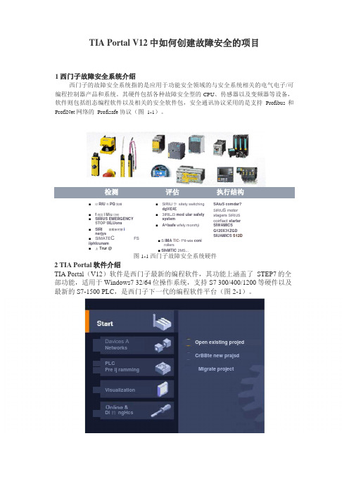
TIA Portal V12中如何创建故障安全的项目1西门子故障安全系统介绍西门子的故障安全系统指的是应用于功能安全领域的与安全系统相关的电气电子/可 编程控制器产品和系统。
其硬件包括各种故障安全型的CPU 、传感器以及变频器等设备, 软件则包括组态编程软件以及相关的安全软件包,安全通讯协议采用的是支持Profibus 和 ProfiNet 网络的 Profisafe 协议(图 1-1)。
检测评估执行结构 ■ 印RIU 书PQ 别哂 ■ f 炯国I Miu 卬畔 ■ SIRIUS EMERGENCY STOP tXLUons■ SIRI 非照审时察inerjys■ SIMATE CFS iiphtcunam■ 上 Trur @■ SIRIIJ 学 sitety switchingdgVi£4£■ 3IRILJ3 mod ular safetysystem■ A^lsafe wfely monrhji 图1-1西门子故障安全系统硬件2 TIA Portal 软件介绍TIA Portal (V12)软件是西门子最新的编程软件,其功能上涵盖了 STEP7的全 部功能,适用于Windows7 32/64位操作系统,支持S7 300/400/1200等硬件以及 最新的S7-1500 PLC ,是西门子下一代的编程软件平台(图2-1)。
SAiuS comdar? SIRIU S motor stagers SIRIUS coirfiact starter SIWAMICS G120X31ZGD SIUAMICS S12D ■ S IMA TIC- f^il-wie coni rollers ■ SlhMTlC 2MS ...Open existing projedMigrate projectVisualizationDavices ANetworks PLCPre ij ramming Di 的 ngHcsCrBBte new prajsd图2-1 TIA Portal软件界面由于原Step7软件中将无法支持最新的S7-1500F /S7-1200F系列的故障安全型CPU等硬件产品,原来基于Step7软件的故障安全的软件包Distributed Safety也将更新为适用于TIA Portal平台下的软件包Step7 Safety advanced(目前最新的版本为V12)。
ate. titan mux 用户手册说明书

Remultiplexing capabilitiesInput ProcessingMULTI-FUNCTION SOFTWARE STREAM PROCESSINGTITAN Mux is a scalable stream processing solution for broadcast, cable, satellite, digital terrestrial television and IPTV applications.It can be easily incorporated into any existing headend for supporting digital turnaround services.The TITAN Mux scalable design reduces deployment time, enables adding new services on the fly and support any video, audio and data service.TITAN Mux can be controlled by PILOT Manager, and easily integrate with any NMS using REST API. TITAN Mux is a true hardware and OS agnostic solution running on any server, any form factor,bare-metal OS as well as any cloud environment.It includes support for IP input-output and support for legacy ASI headend using PCIe ASI cards.TITAN Mux eliminates operationalheadaches and ensures high scalability, flexibility and availability.• Service pass-through & remapping • Service duplication• Service generation from incoming components or data streams• Component pass-through, remapping, filtering and duplication•Smart service replacementManage PSI/SI tables• Disabling • Pass-through• Internal Carouseling: Generates table body and passes through incoming descriptors•Multicast Carouseling: Buffers incoming table, may restamp some fields and streams at configurable pace.• MPEG TS inputs: CBR, up to 200• IP I/O’s (1Gig-E or 10 Gig-E), ASI I/O’s (optional PCI card)• IP/TS/service/PID level monitoring • Instantaneous bit-rate monitoring• ETSI TR 101 290 instantaneous analysis • Failover Active or Passive modes • Automatic or manual switch back•Redundancy on TS loss or on any ETR 101-290 P1 triggers.• Dynamic Statmux Pool : the bitrate ofvideo streams will take all the available bandwidth in the MPTS, dynamically adjusted according to the bitrate of generated SI tables, audio streams,…• VBR Reservation : Also called dynamicshaping. Titan MUX adapts the bandwidth reservation dynamically to ensure that all the external VBR data are evacuated within a specific delay (external SI (EIT), EMMs,…)Statmux w/ VBR Reservation9000800070006000500040003000200010000VBR DataService AService BService CService DMultiplexing EngineFor more information, visit our website at 。
退火炉L1功能描述及系统配置

热处理设备的控制lal ITEM 1001 : 过程控制系统1.介绍被讨论的控制系统以流行与强大的微处理器控制系统为基础,由富有经验的STEINHEURTEY根据现代炉子控制需求而设计。
被计划的微处理器控制系统关于控制可信度,操作设备和数据储藏可能性与特别的要求一起设计。
我们的计划包括基于SIEMENS PCS7控制系统的解决办法。
STEIN HEURTEY最新在处理线方面使用西门子S7的业绩:-2004 美国钢铁公司S LOVAQUIA Silicon annealing & coating line-2004 PANZIHUA 中国P.R CGL-2003 WISCO (PCS7) 中国P.R CGL-2003 EKO STAHL(Arcelor) 波兰CGL-2003 BORCELIK (Arcelor) 土耳其CGL-2002 SALZGITTER (PCS7) 德国CGL-2001 NOVOLIPETZ 俄国CGL-2001 WUPPERMAN 德国CGL-2000 RAUTARUUKKI 芬兰CCL-1998 SICOS 泰国CCL无二级的操作:一级控制系统完全能够独立于二级和更高的计算机进行操作,它能够在二级系统停机的情况下无中断的持续保持生产远程I/O:为了节省电缆,许多远程I/O安装在现场和电气室内。
还有,一些设备还具有外部总线通讯能力并与Profibus DP进行数据交换。
al ITEM 1001 : 过程控制系统2.描述(基于西门子PCS7控制系统)以下描述基于西门子PCS7控制系统:2.1.总体特征我们选择西门子PCS7控制系统是为了现代生产线的工业需求。
它设计灵活的,综合了较高制造水平,有最大可信度。
STEIN HEURTEY也认为,它安装了以下当今工业控制完全必要的特征设备:-分布控制和数字控制能力-简单的和安全处理控制-易于使用的软件-开放式系统-模块化的硬件和软件-方便的通讯能力-全面集成的现场总线-自诊断功能2.2.系统配置下面的结构图表明了自动化系统设备和通讯设备:alITEM 1001 : 过程控制系统FURNACE ARCHITECTURE DIAGRAML 1 HMIDEVELOPMENTSUPPLIED BYColorprinterFURNACE LEVEL 1FURNACE :RemoteSIEMENS PCS 7ENGINEERING Line driveFURNACEELECTRICALRemote)炉子控制系统配置图CONTROL ROOMCOMPUTER ROOML1 HMILEVEL 2 FASCOMPAQALPHA SERVER(VAX STATION)printerprinterFASCONSOLESYSTEMELECTRICALCOMPANYLEVEL 2FAS HMICONTROL SYSTEMTCV TE XV Z SINSTRUMENTATIONRemoteI/OPLC ROOML1STATIONcontrol systemor Level2ROOMI/O1 in electrical roomProfibus D PEthernetEthernet (optical fiber)EthernetEthernetopticalfiberSwitchal ITEM 1001 : 过程控制系统2.3.提供的硬件范围一个柜子能容纳装载有数据目录的过程控制站,控制环路的进程和监视也有逻辑序列和安全性.柜子被设计安置在电气室里面,尺寸和重量大概是下列各项:-长度: 4 000 mm-高度: 2 200 mm-深度: 600 mm-重量: 1 300 kg过程控制站主要包括:集中站包括:-一个主要框架UR2(9插槽)-一个控制环路控制器(CPU 416-2)-一个提供功率组件(PS 407 – 10A)-通讯版块:o CP443-3 (profibus DP) –如果有必要o CP 443-5 (以太网). –如果有必要远程I/O站:-这个远程I/O站模块(ET200M)是为了将电缆花费减少到最小而设计,被提供的数量如以下各项:数量: 5-2个分别在PHS炉子/ RTF区域-一个在炉子RCS区域-一个在冷却塔-一个在MCC电气室每一个包括:-一个远程I/O模块ET 200 M-一个电源模块PS307-5A-一个通讯模块 :(Profibus DP) IM 153-1-模拟I/O的板-数字I/O板I/O模块的数量是大概估计值(在设计阶段数量将最终被定下来):-热电偶输入模块(8 inputs) - SM 331-模拟量输入模块(8 inputs 4-20 mA) - SM 331-模拟量输出模块(4 outputs 4-20 mA) - SM 332-数字量输入模块(32 inputs 24 VDC) - SM 321-数字量输出模块(32 outputs 24 VDC) - SM 322将提供15%的备用输入和输出I/O将提供10%的备用插槽al ITEM 1001 : 过程控制系统描述型号备注主板UR2 9个插槽CPU inclufing :. 1 以太网端口. 2 Profibus端口CPU 416-2电源板PS 407 – 10 A附加以太网通讯板块CP 443-1 如果需要附加Profibus通讯模块CP 443-5 v如果需要远程I/O模块ET200 M远程I/O-带电源模块PS 307 – 5 A远程I/O-通讯模块IM 153-1数字量输入模块(32 inputs) SM 321数字量输出模块(32 outputs) SM 322模拟量输入模块(8 inputs) SM 331模拟量输出模块(4 outputs) SM 332SM 321 digitalinput moduleSM 331Analoginput moduleSM 332Analogoutput moduleSM 322digitaloutput moduleaa lITEM1001 : 过程控制系统 2.4.操作站(在控制室)操作员通过两台安装有操作站监视软件的台式机来进行过程监督管理.每个站都至少包括以下设备,如果有必要,他们的特征与版本将根据购买时间进行修订.2.5.编程单元(在PLC 室里面)提供手提电脑进行编程,并将它安放在PLC 室。
- 1、下载文档前请自行甄别文档内容的完整性,平台不提供额外的编辑、内容补充、找答案等附加服务。
- 2、"仅部分预览"的文档,不可在线预览部分如存在完整性等问题,可反馈申请退款(可完整预览的文档不适用该条件!)。
- 3、如文档侵犯您的权益,请联系客服反馈,我们会尽快为您处理(人工客服工作时间:9:00-18:30)。
17
THE END
© 2012 HALLIBURTON. ALL RIGHTS RESERVED.
18
RH OR HVT HYDRAULIC-SET RETRIEVABLE PACKER
LANDING NIPPLE
© 2012 HALLIBURTON. ALL RIGHTS RESERVED.
2
HYDRAULIC CONTROL LINE SURFACE-CONTROLLED TUBING-RETRIEVABLE SAFETY VALVE SIDE POCKET MANDREL
SLIDING SIDE-DOOR® CIRCULATING DEVICE RH HYDRAULIC-SET PACKER
CIRCULATING DEVICE
BLAST JOINT
TWB PERMA-SERIES® PACKER NO-GO NIPPLE
© 2012 HALLIBURTON. ALL RIGHTS RESERVED.
Gas Lift Packoff Installation
© 2012 HALLIBURTON. ALL RIGHTS RESERVED.
16
Packoff Gas Lift Installation B Mandrel
© 2012 HALLIBURTON. ALL RIGHTS RESERVED.
FLOW COUPLING LANDING NIPPLE FLOW COUPLING SIDE POCKET MANDREL LO LINER HANGER SIDE POCKET MANDREL
Single Selective Completion System ( Special FeatureLO Liner Hanger )
© 2012 HALLIBURTON. ALL RIGHTS RESERVED.
6
BK Latch & JK Running Tool
© 2012 HALLIBURTON. ALL RIGHTS RESERVED.
7
RA & RM Latches JC Running Tool
© 2012 HALLIBURTON. ALL RIGHTS RESERVED.
13
Camco Type OM Kickover Tool
© 2012 HALLIBURTON. ALL RIGHTS RESERVED.
14
Ability to Work in High Angle Wells
© 2012 HALLIBURTON. ALL RIGHTS RESERVED.
15
8
RK Latch RK Running Tool
© 2012 HALLIBURTON. ALL RIGHTS RESERVED.
9
Non-Orienting Kickover Tools
© 2012 HALLIBURTON. ALL RIGHTS RESERVED.
10
Merla Type Orientating KickoverToolGAS LIFT
Single Retrievable Gas Lift Completion TUBING-RETRIEVABLE
SAFETY VALVE
(For Offshore Wells)
SIDE POCKET MANDRELS WITH GAS LIFT VALVES AND LATCHES
3
Gas Lift Installations
© 2012 HALLIBURTON. ALL RIGHTS RESERVED.
4
Unloading Continuous Gas Lift
© 2012 HALLIBURTON. ALL RIGHTS RESERVED.
5
Unloading Intermittent Gas Lift
© 2012 HALLIBURTON. ALL RIGHTS RESERVED.
11
Camco Type Orientating Kickover Tool
© 2012 HALLIBURTON. ALL RIGHTS RESERVED.
12
Camco OK Type Kickover Tool
© 2012 HALLIBURTON. ALL RIGHTS RESERVED.