AU6980安装操作说明
Au698x 量产工具操作手册

Au698x量产工具操作手册2009.06.26目录1. 软件的运行环境 (1)2. 软件主要功能 (1)2.1FLASH支持部分 (1)2.2U盘制作功能 (1)3. 快速使用方法 (2)4. 设定界面说明 (5)4.1密码设定 (5)4.2存储器设定 (6)4.2.1存储器类别 (6)4.2.2量产设定 (7)4.2.3 其他设定及老化设定 (10)4.3装置方式设定 (11)4.3.1 普通盘 (11)4.3.2 本地盘 (12)4.3.3 只读盘 (12)4.3.4 加密盘 (13)4.3.5 AES盘 (13)4.3.6 AutoRun盘 (14)4.4U盘信息设定 (15)4.4.1 客户信息设定 (15)4.4.2 SCSI (15)4.4.3 USB (15)4.4.4 序列号设置 (16)4.5坏磁区设定 (17)4.6其它设定 (19)4.7导入配置和导出配置 (20)1. 软件的运行环境适用系统:Windows 2000,Windows XP。
量产工具是绿色版的,不用安装即可以使用。
2. 软件主要功能2.1 FLASH支持部分1) 最多可以16个U盘同时量产。
2) 支持不同型号的FLASH同时量产,并可单独停止或开始任意一颗的量产。
3) 支持安国不同U盘及MP3主控混合同时量产。
4) 自动识别FLASH型号、ID、CE数目,也可手动选择FLASH型号进行量产。
5) 支持单贴、双贴、单通道和双通道。
6) “低格检测”设定,可支持Half Page及其它特殊状况的FLASH。
7) 提供手动选择ECC设定。
8) 有高级格式化和低级格式化两种扫描方式:a. 高级格式化指扫描时直接读取FLASH的坏块信息,分为全新、全新+AA55、量产过和清空四个扫描级别:全新:直接读取原厂坏块信息。
全新+AA55:全新扫描+简单的检测。
量产过:直接读取上一次量产写入的坏块信息(必须是该量产工具量产过)。
Au3教程——精选推荐
Au3教程⾃动安装脚本制作⼊门(⼀)⼀、制作⽬的和原则说到⾃动安装,其⽬的就是模拟⼿动操作,⾃动完成对指定按键的点击和输⼊指定内容,处理可能出现的情况,最终完成程序的安装和设置。
也许有⼈说这样就明⽩了,⽤AutoIt⾥的MouseClick、Send来完成点击和输⼊,只要抓好点击的坐标就⼀切搞定了啊!这当然不能说不是个办法,但做出来的成品可能只能在你⾃⼰的电脑上能⽤,说不定下⼀次你⾃⼰也没法⽤了。
因为每个⼈的电脑是不⼀样的,安装窗体在不同分辨率下的位置也是不⼀样的,如果⽤这样做的脚本在别⼈电脑上操作,就会看到⿏标经过N次狂奔后,打开了M个窗⼝,却没有点到你要的东西(⽤来整⼈倒不错)。
我们的⽬的是让脚本能有效的在其他⼈电脑上运⾏安装,处理遇到的情况,完成设置或注册等动作,然后结束。
所以制作的原则就是通⽤、精确和可*1、尽量少的⽤⿏标模拟点击的⽅法,实在⽤要也要做到保证点击坐标的可*原因上⾯都说了,但有时不得已⽤到点击坐标时怎么办呢,你先想想吧。
后⾯告诉你我的办法2、尽量少⽤sleep等待语句,⽽换⽤其它准确的时间判断语句有的朋友喜欢⽤sleep在⼀个操作后等待⼀下,来保证脚本的可*性,其实这却是个不可*的做法。
因为每台电脑的性能有所差异,在不同的情况下也有差异,在你的电脑上制作脚本时要停顿5秒的,在⼀台第旧的电脑上可能要等待20秒也不⼀定。
AutoIt⾥是有解决⽅法的,⽐如winwaitactive,winwaitclose等,再不⾏⾃⼰写判断啦!3、尽量考虑可能出现的情况有的程序在安装时会提出⼀些要求,⽐如需要更新什么⽂件或进⾏什么操作,⽽且未必在每台电脑上安装时都会出现,这就要我们在做好脚本后多在不同环境测试⼀下,考虑到⼀些常见的问题⼆、如何学好AutoIt对于AutoIt我也是个菜鸟,没有什么经验可谈,但我觉得有三点⼀定要做到1、充分利⽤帮助⽂件。
AutoIt的帮助⽂件写的⾮常详细,索引和搜索功能使它在查询上⾮常⽅便,⽽且每个命令最后都有例⼦。
操作安装说明书
操作安裝說明書一、安裝網路視訊 Install the webcam1.將網路視訊裝到電腦的USB孔後,電腦會找到新硬體,並啟動新增硬體精靈,請選擇〝自動安裝軟體〞,並點選〝下一步〞。
Plug in the USB port, Computer will find out the new device, startthe new device installation guide as following, and choose the “AutoInstallation”, then press next step.2.點選〝繼續安裝〞Click the “Continued Installation”01023.軟體安裝中...The Software is installing...4.點選〝完成〞 Click “Finish”03045.開啟我的電腦,下方會出現USB視訊裝置的圖示,開啟後可以 看到自己的影像,並可拍照。
Click into “My computer”, there’s a new icon of USB webcam, click this icon, then display your image, you can take photo too.二、安裝網路視訊驅動 Install the Driver1.將驅動光碟放入光碟機中,並點選〝LiveCam 690 Driver〞 選項Put the disc into disc machine, click on “LiveCam 690 Driver”05062.程式安裝準備中Software arrangement 3.點選〝下ㄧ步〞Click the 〝Next Step〞07084.程式安裝中... Installing...5.點選〝繼續安裝〞Click the “Continued Installation”09106.點選〝繼續安裝〞Click the “Continued Installation”7.點選〝完成〞Click on “Finish”11128.開啟桌面上的捷徑 ,可以進行影像的預覽。
优盘量产工具集(芯片精灵)

慧荣SMI方案SM321/SM325/SM3252/3253优盘量产工具SM32x_I1126/read.php?tid=140913慧榮SM3211BC1_I1020_P_091026量產工具(2009.10.26更新)/read.php?tid=139044最新SMI SM3251/SM3252/SM3252BB 量產工具I1023/read.php?tid=136597SM3255量产工具,SM3255_I1016 V2.02/read.php?tid=133578慧荣SM3255_I0918最新量产程序V2.01/read.php?tid=133511最新SMI SM3251/SM3252 量產工具I0910 ********/read.php?tid=133048慧荣SM325X量产工具I0626汉化版(仅适用于SM325X主控)/read.php?tid=117634SM321/SM324/SM325/SM3252优盘量产工具SM32x_I0414/read.php?tid=108286&fpage=2SM325x-BA TSB 43nm D2 Flash专用量产工具/read.php?tid=128645SM32X_I0112量产软件(2009年第一版数码之家首发)/read.php?tid=103204慧荣SM32X_I0112量产软件汉化版/read.php?tid=113384SM32X_H1226量产软件(2008年最后一版)/read.php?tid=78998SM32X_H1226量产软件V1.17.44 V3 12/18 汉化版/read.php?tid=84343慧荣SM32x主控最新量产工具V1.17.42 H1029 (20081101发布)/read.php?tid=65117SM324BC+K9WAG08U1M SLC FLASH专用版量产工具(20081022发布) /read.php?tid=60187SM3251_321CC_DG_针对黑片的最新量产工具V1.17.40 (20081008发布)/read.php?tid=59116SM32X量产工具H0828版/read.php?tid=57092慧荣SM32x主控最新量产工具V1.17.38 H0821/read.php?tid=51044SM32X量产工具H0328汉化版/read.php?tid=30538SM32X量产工具H0229(V1.17.20汉化版,纯手工录入汉字)/read.php?tid=27371SMI SM32x H20080109量产修复工具简体中文汉化版/read.php?tid=272232008年首版SMI H0109量产工具及FLASH支持列表/read.php?tid=27218SM32x量产工具G2*******汉化版-每个字都是手工输入的,望支持/read.php?tid=25553SM32x量产工具G1219汉化版/read.php?tid-25553.htmlSM321&SM323 U盘量产修复工具下载,适用朗科U盘/read.php?tid=3970SMI32X主控U盘量产修复程序下载/read.php?tid=5811SM321最新版本1.7量产工具(支持多种芯片)/read.php?tid=15377最新惠荣SMI SM223 CF卡量产工具,支持SSD固态硬盘量产!/read.php?tid=52025群联Phison方案群联PS2251-xx最新量产工具MPALL 2.01版/read.php?tid=132415PHISON MP2239 v1.04.00(PS2239量产工具)/read.php?tid=127107群联PS2233主控方案量产工具V1.11/read.php?tid=106579UP15/PS2237主控量产工具v1.06/read.php?tid=103311群联Phison UP10~UP14 u盘量产工具V1.08官方版本/read.php?tid=91102#0群联助手v1.00(U盘自动化量产工具箱,包括V1.96/V1.03/V1.06)/read.php?tid=84963群联Phison UP10 UP12 UP13 UP14 u盘量产工具V1.06官方版本/read.php?tid=68107Phison PS2233(UP16)量产工具v1.03 破解版支持自定义VID PID【仅发数码之家】/read.php?tid=65779PS2233(UP16)量产工具V1.03数码之家首发/read.php?tid=61127PS2232(UP13/UP14) MP TOOL V1.05.00新鲜版(目前最新)/read.php?tid=60779&fpage=3群联UP13/14(PS2232)最新量产工具放出(版本号奇怪,为1.0.20.3,不是1.96往后排)! /read.php?tid=60541Phison UP13/UP14/UP12(PS2231/PS2232)量产工具V1.96/read.php?tid=31113PHISON UP12(PS2231) &UP10(PS2136)量产工具V1.89/read.php?tid-20398.html群联phison 2143-2134系列U盘量产格式化修复程序下载V1.28/read.php?tid=5806群联phison UP8-R 主控U盘量产格式化工具下载V2.0/read.php?tid=5800PHISON UP8-Y 专用量产工具V1.65/read.php?tid-18943.html群联UP10(PS2136)、UP11低格工具/read.php?tid=15433phison UP10主控U盘量产修复工具下载v1.78,感谢zhby9462提供/read.php?tid=6984群联Phison最新版量产工具V1.81 适用于PS2136(UP10)等主控/read.php?tid=15046群联Phison UP12 (PS2231)量产修复工具V1.85/read.php?tid-17925.htmlPNY U盘修复工具Pretest v1.11(群联)/read.php?tid=16858群联Phison UP10低格工具 1.30.0.0版下载/read.php?tid-23352.html群联Phison UP14(PS2232)主控u盘加密工具!/read.php?tid=60599群联Phsion UP10 ~14(PS2232)u盘主控最新加密工具V2.64中文版。
优盘
iCreate i5068主控量产检测工具下载V3.11
/read.php?tid=5261
UT163 U盘量产修复工具下载USBest(MP tool)
/read.php?tid=4239
SM321&SM323 U盘量产修复工具下载
具体使用:看是什么样的U盘,先用U盘检测工具检测一下你的U盘的主控芯片的型号,然后下对应的主控量产程序对其进行格式化,一般都能解决问题的。
要补充说明的是,用U检测工具检测的清华同方主控芯片都使用的芯邦的,有问题的朋友们可到网上去下载试下看,希望这能给你带来好运。
/read.php?tid=4335
iCreate 5122方案U盘量产修复工具下载V1.08
/read.php?tid=4333
iCreate 5062LQ主控U盘量产工具下载
/read.php?tid=4324
3:修改盘符的方法
把RAW的盘符改一下,如果是C、D、E、F,F是RAW盘符,就把F改成E,就可以恢复了。
4、使用EasyRecovery Pro软件恢复:
1、使用EasyRecovery Pro 6.06,选择数据恢复Advanced Recovery(选用高级选项自定义数据恢复功能);
U盘不能格式化、打不开的维修方法 来源:网络 作者: 时间:2008-04-05 如果你是菜鸟,你的U盘或MP3 坏了,自己又不会修,是不是只能拿去修呢,这完全不必,下面来看看吧。
最近我的2G金士顿U盘插上电脑,显示只有8M。于是我就用WINDOWS自带的格式化工具格式,但却发现无法格式化,这下我急了,于是我就上网搜索一番。下载了一个U盘的万能格式化软件对其进行格式化,但结果却出乎意料,还是不行,并提示U盘卷有问题,且无法完成格式化。
AU简明操作手册(480-680)
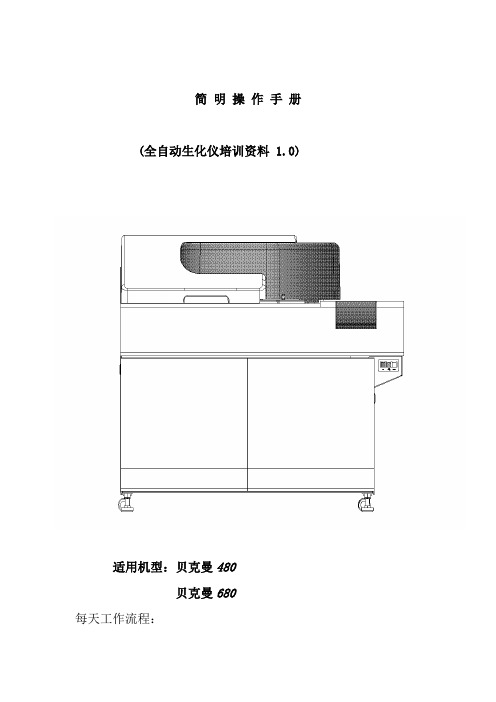
简明操作手册(全自动生化仪培训资料 1.0)适用机型:贝克曼480贝克曼680每天工作流程:一、开机前检查;二、开机;三、修改日期索引;四、检查、添加试剂;五、做质控,查看质控结果;六、如有必要,做定标;七、做定标项目的质控,查看结果;八、做标本;九、插入急诊标本;十、查看标本结果;十一、传输标本结果;十二、关机;十三、常见符号;十四、常见报警。
仪器主要单元介绍仪器主要界面介绍主要按键介绍一、开机前检查1、检查样品配送器、试剂配送器是否泄漏;2、检查清洁剂蠕动泵装置是否泄漏;3、检查主清洁剂的数量并补给;4、检查并清洗样品探针、试剂探针和搅拌棒;二、开机开启键,仪器主机以及操作电脑将会自动启动,操作电脑进入“修改日期索引”界面。
三、修改日期索引1、开机后,仪器自动进入以下界面2、点击,仪器将自动建立一个日期索引。
注:每天必须修改日期索引,并且每天只能修改一次,如果当天第二次开机,则选择“ ”,然后点击,仪器将不建立新索引。
四、 检查、添加试剂2、点击“”点击“”后,进入以下界面点击“”点击“”后,进入以下界面1、在此查看各试剂剩余测试点击“ ”,进入以下界面1、如果添加的试剂品种很多,就使用第一个选择;2、如果添加试剂品种只有几个,使用第二个;3、第三个选择几乎不用;4、试剂状态显示红色的时候,使用“试剂复位”。
选择好后,点击“”,仪器将对试剂进行检查。
五、做质控,查看质控结果1、做质控:将质控品放在“绿色”样品架相应的位置,将“绿色”样品架放置于仪器进样轨道上,点仪器“开始”键。
仪器自动做设置好的项目的质控。
2、查看质控结果:在中文报告系统,点击“质控” “质控图”,即可查看质控结果。
六、定标点击“”后,进入以下界面点击“”点击“”后,进入以下界面2、选择需要定标的项目将定标液放置于“黄色”定标架指定位置,在“蓝色”试剂空白架的“1号”位置放水。
“蓝色”架前,“黄色”架后,放置于仪器进样轨道上,点击“开始键”,仪器将自动定标。
人为中断移动硬盘格式化再次点击出现windows无法完成格式化怎么办
人为中断移动硬盘格式化过程再次点击硬盘出现windows无法完成格式化怎么办时代发展了,人们拥有电子资料的需求越来越大,那么为了保存相关电子资料,对移动硬盘的空间需求越来越大。
2008年拥有一个500G的移动硬盘就算是比较高的待遇了,直到现在,拥有一个1T、2T的移动硬盘又算得上什么难的事呢?购买新移动硬盘后,有的新手不了解硬盘格式化的操作程序,在右键点击格式化(未选择快速格式化)想对硬盘进行格式化,但事与愿违,由于硬盘的存储空间大,格式化过程非常非常缓慢,2T移动硬盘在未选择快速格式的情况下可能要花费近约24小时的时间,进度缓慢又浪费时间,于是就想当然的取消格式化,转而想用快速格式化,然而这一动手,问题就出来了:取消后,硬盘空间变为0字节,双击硬盘打不开,总是提示要进行格式化;你按照它的提示进行格式化,却再也进行不了格式化动作了,因为系统会老是提示你“windows 无法完成格式化,要先启用分区和卷”,这下麻烦大了吧?是硬盘坏了吗?怎么解决呢?下面请跟小编一起学习一下解决办法,搜罗网上,方法很多,希望能给大家提供一些帮助,一些问题可能还需要用不同的方法解决,各位大虾就多多花费点精力好好看看吧。
中间还附有安装XP系统的方法,大家也可以看看啊。
windows无法完成格式化怎么办|浏览: 121854 |更新:2012-07-24 16:50 |首先要提前声明的一点是,如果你的U盘是硬件损害,怎么修复都是不行的,所以如果你尝试了下面的方法仍然无法格式化就不要喷了,大家都不容易,还得天天看别人脸色。
下面的方法只是适合软件损坏,或者电脑本身的故障。
方法一:改变磁盘路径1. 1按下快捷键win+r,打开运行窗口,输入cmd,按下回车键,打开命令窗口2. 2命令窗口中输入命令:format f: /fs:fat32 注意中间的空格,按下回车键即可执行命令。
命令中,f:指的是你的优盘的盘符比如在这里看到的盘符是H:3. 3在开始菜单打开控制面板在控制面板中,将查看方式改为小图标,然后在找到管理工具,打开它4. 4在管理工具中,找到计算机管理,双击打开它5. 5在计算机管理中,你会看到所有的磁盘,找到U盘所在的磁盘,右键单击它,然后选择【更改驱动器和路径】6. 6打开一个对话框,在右侧的下拉列表里选择盘符为A,然后点击确定按钮。
U盘量产教程等
AU6983 4G三驱三启成功!【教程】三驱是指将U盘分为3个驱动器,插电脑上你会看到一下子多出来三个盘符;三启,即这三个驱动器都能当启动盘用,就是在开启电脑的时候你可以选择三种启动方式:一、首先说说AU6983的USB-CDROM启动和U盘分区的量产具体步骤:(即把一个分区模拟成一个USB接口的光驱,里面放入模拟的光盘,即ISO光盘镜像,我使用的是深蓝技术Ghost XP SP3 纯净版4.0.iso;剩余的部分同时分成两个区块,为的是一个做USB-ZIP 启动,一个做USB-HDD启动。
)1.ChipGenius 是用来查U盘的主控芯片的工具,通过ChipGenius你就知道需要哪种量产软件来给U盘分区了。
比如我用查到我的U盘主控是安国品牌,型号是AU6983。
我的U盘是爱国者L8202 4G,用ChipGenius查是安国AU6983芯片。
本人喜欢拆东西,将U盘拆开看了看:拆开可以看到主控是AU6986,flansh为Micron(美光)MT29F16G08MAA,所以有时候用软件检测也是不可靠的。
2.然后在网上找到AU6986的量产软件最新版AlcorMP 090515.01。
版本不适合,重新找另一个版本。
3.点“设定”进入,因我的U盘是量产过的,就是分过区。
所以这里“扫描级别”是“量产过”,当然我也可以选别的,但是那样就要重新扫一遍,且太慢,没必要。
第一次量产的朋友就选默认的,以后再量产就是选“量产过”。
点“装置方式设定”选“AutoRun”,默认方式,自动弹出一个窗口,因为我的镜像是ISO格式的,所以我选了“ISO Mode”,找到“深蓝技术Ghost xp sp3”,点打开。
注意下面这个100%的意思是U盘的总容量减去“深蓝技术Ghost xp sp3”占用的空间剩余的部分,即4096M-700M=3396M,如果你只想把U盘做成一个USB-CDROM的启动盘和一个用来放文件的普通U盘,那就不要动这个这个指示光标,保持它在100%的位置,这样你量产好的U盘在电脑就只显示两个盘符,一个CD光驱,一个就是普通可移动磁盘了。
(AU6980)完美量产CDROM教程
最近入手一个迷你王®商务型爱国者U盘,用ChipGenius检测结果如下:显示是AU6980的主控,但用遍了量产工具,从6.18到v.2.1.2.0,都无法识别这个U盘的主控.在网上闲逛的时候发现安国出了新版的量产工具,是08年12月8号更新的,用这个版本的量产工具终于实现了完美量产!!量产成功后,在我的电脑中显示两个盘符,一个是CDROM,一个是移动磁盘.下面附上量产工具,是完全绿色的,不用安装!:[attachment=111374]下面进入主题:量产开始!!!!!!!!!!!!第一步:先要把U盘拨下来,先运行量产工具:AlcorMP.exe,然后插入U盘,点"更新",正确识别到U盘:第二步:进入"设定"进行设置:进入设定的时候会提示输入密码,密码默认为空!第三步:进行"存储器设定",注意两个地方,一个是要决定选择低级格式化还是高级格式化(要低格的话,时间会长很多),然后初视情况选择扫描级别,注意就是ECC要选一定要选"1",!,再就是要选中"量产后擦除FLASH",让他量产完后直接把移动盘部分格式化!第四步:进入关键的一步了!!到"装置方式设定",在这儿当然要选Autorun 这个项目了,点中后,注意!!一定要用鼠标再点一下Autorun这个单词这个位置,会弹出一个新对话框,这是个关键,只有点了这个才会出现一个是选择IMG或是ISO的启动文件的对话框!,如下图:第五步:其它地方都默认就可以了,然后返回主界面,点"开始"就可以了!量产结束后如下:附后:终于传完了!好累啊!不过还是没弄明白,这个U盘到底是什么主控的啊?可能是软件没有识别正确,期待改进!还有一个注意事项:要在设定的"坏磁区设定"这儿的"关闭MP时卸载驱动"点上,这样退出软件后U盘才能正常使用!!千万注意哦!。
AU6980中文资料
元器件交易网
元器件交易网
'
*
( $ "' '
$" ) "' & '
$)
! ' " !
" $" ' ) " "
# # $ % ( $" $ ) " & ' ( ' "' ) *
& ' ' "*
$ " )
$
8;C 8 C来自$ +5
!
5
Q 8
C C C
/
C?% C/ +
+
85
/) ) + '
Q 8
+4
1
9&'
! 8
C C C?% +/9# ? / )
2
9&' 2 &
) ) C + ' ) 8 88 > 88
!
5
*
9 *
&
;&
8> 8-
+
C C C
/
9&) 1
! 8 !
??% ?/A
?%
9&) 1 & & ;& +
µ µ 9 $6' 9 $6' ()&& 9 $6' > > > ρ ρ ρ % ) ) ) ) $ *
*
? + ? ) ) )
/ +
安国(Alcor)AU6983 1G U盘写保护修复记档
安国(Alcor)AU6983 1G U盘写保护修复记【图+文】同事小妹说她的U盘写保护了,不能往里面复制文件,也不能删除,提示信息是“请检查驱动器\Device\Harddisk1\DR18”。
怀疑是中毒,可是杀毒还是照样弹出“写保护”提示。
但是可以把文件复制出来。
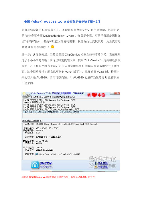
我告诉她让我试试吧,反正我有过修复U盘的经验哦!!第一步:U盘拿来后,当然还是用ChipGenius检测主控和芯片型号。
我在这里走了个小小的弯路啊!在这里特别提醒大家,使用“ChipGenius”一定要用最新版本的(右下角有个检查更新,点击后直接跳出到U盘精灵最新版的官方下载页面。
这个很重要哦!现在已更新到V3.01版了)。
我开始要V2.56版,检测出来的芯片是AU6980,结果可想而知,用AU6980的量产当然是连U盘都识别不出来的。
这是用ChipGenius v2.56版测试出来的结果,其实是AU6983的主控第二步:找到AU6983相适应的量产工具AlcorMP(100421),安装好后先运行Al corMP.exe,然后再插上U盘。
这时你回发现U盘自动识别出来(如果量产工具不对的话,U盘肯定识别不出来)。
第三步:点击设定按钮,会弹出一个输入密码的对话框,默认密码是空的,所以直接点确定就可以了。
按照这个页面设置进入设定页面后,第一个选项卡“存储器设定”中选项全部默认设置,但“量产后擦除flash”这个选项最好选上。
!!zougy1168互联网上最最爆力、最最新奇、最最热门的拆客之家,满足你窥探的欲望!--- 相关话题∙Alcor AU6983/AU6985/AU6987/AU6990主控量产工具【20100517】(主控型號全)∙我的 Toshiba(东芝)SK6211BB/TC58NC6686G1F 量产成功了 ∙ [分享] 朗科 U208 16G 量产实例关键词: AU6983 写保护回复 引用举报顶端coco_lee 离线级别: 数码8级 UID: 221538精华: 0发帖: 34M 币: 67 M专家: 1 级贡献值: 0 点 在线时间: 13(时)注册时间: 2008-06-28最后登录: 2010-05-191楼 发表于: 昨天 16:17只看该作者 ┊ 小 中 大第四步:其他的设置都按默认设置就可以了。
Alcor AU6980-6981量产工具操作说明V6.18

量 产 工 具 操 作 说 明目录1、软件的运行环境及特性 (3)2、功能: (3)3、使用方法 (3)4、进入设置 (7)4.1密码的设定 (7)4.1.1 量产工具密码设定: (7)4.1.2密码更改: (7)4.2存储器类别 (8)4.2.1存贮器类型: (8)4.2.2量产设置: (9)4.3装置方式 (12)4.3.1 普通盘: (12)4.3.2 本地盘: (12)4.3.3 只读盘: (13)4.3.4加密盘: (13)4.3.5 AutoRun盘: (14)4.3.6 分区设置 (15)4.3.7二次开发设置 (16)4.4U盘信息 (16)4.5坏磁区 (17)1、软件的运行环境及特性系统需求:Windows 2000,Windows XP。
注:编号MP6.15以后的量产工具是绿色版的量产工具,不用安装即可以使用。
2、功能:1)支持所有主控U盘及所有MP3同时量产2)支持不同Flash同时量产3、使用方法(1)双击量产工具包里的AlcorMP.exe图标(),进入量产工具的界面:(2)插入U盘,量产工具自动识别U盘使用的Flash类型及相关信息:(3)点击“开始”键将所有的flash进行量产格式化:(4)单个量产开始 --- 代表单个Flash开始量产结束 --- 代表单个Flash结束量产(5)当状态栏显示“绿”色字体信息时,关闭量产工具并重新插拔一次U盘即可使用。
(6)单击右上角红色标记区域会显示量产工具版本信息:(7)双击工具信息显示栏,即弹出下图的信息窗口,显示当前U盘的主控型号、Flash 型号及ID号。
(8)配置端口:打开量产工具,选择“配置端口”,弹出USB配置端口(如下图),找到HUB端口,根据客户自己的要求,选择自己所要使用到的端口。
选择好后,点击"确定"保存设置。
这个功能有利于工厂生产时判断故障,提高生产率。
4、进入设置在使用量产工具生产U盘之前,首先应用工具提供的配置功能将生产参数设置好,然后在进行U盘扫描和格式化。
AFL 音频光纤链接模块说明书
DN-6980:A • 05/01/2009 — Page 1 of 2AFL-RM, AFL-TM, AFL-RS, AFL-TSAudio Fiber Link ModulesDN-6980:A • C-1506980c o v 2.J P G 6980c o v 1.j p g ,h 6980c o v 2.J P GGeneralThe AFL-TS/AFL-TM (single- or multi-mode transmitters) and AFL-RS/AFL-RM (single- or multi-mode receivers) are Audio Fiber Link M odules that distribute low-level audio signals via fiber-optic media.The AFL-TS/-TM transmitter accepts low-level audio signals from the DVC-AO. The AFL-TS/-TM then converts the low-level audio signals to modulated light, which is transmitted through fiber-optic cable. The AFL-RS/-RM receiver accepts that modulated light at the other end of the fiber-optic cable,then converts the modulated light to low-level audio to feed AA-30, AA-100, AA-120, or XPIQ amplifiers, or (if required) the next daisy-chained AFL-TS/-TM.Audio Fiber Link (AFL) modules are powered from nonresetta-ble 24 DVC output from power supplies that are listed for fire protective signaling service.ApplicationsAudio Fiber Link modules may be used in systems where:•The use of wire media is not possible due to security requirements.•Fiber-optic cable is already installed and available for low-level audio distribution.•Significant distances between DVC-AO and remote ampli-fier cabinets dictate the use of fiber.•High-intensity electromagnetic fields of audible frequencies could be coupled to low-level audio over wire.•Both distance and physical location of remote cabinets require the use of star topology.Up to 50 AFL transmitters maybe be connected to the output of a DVC-AO.A maximum of ten amplifiers may be fed from AFL receiver output; and a maximum of ten AFL transmitters may be fed by a single AFL receiver.The maximum series connection of audio fiber links is two AFL transmitters/receiver pairs deep.APPLICATION NOTES:• A system requiring many fiber links may also require larger batteries and external chargers. Please refer to the POWER REQUIREMENTS section on page 2.•AFL transmitters should be powered by the 24 VDC UL-listed power supply connected to the same reference (bat-tery negative) as the audio signal source (DVC-AO, AFL receiver).•Class A low-level audio riser cannot be implemented when using AFL modules.•Any combination of up to 50 AFL transmitters and AA-30,AA-100, and AA-120 series amplifiers may be connected to the output of any one DVC-AO. All of the AFL-transmitters must remain in the same cabinet as the DVC-AO.•Once audio system installation is complete, the audio gain level must be adjusted. See Installation Document 52230for instructions.InstallationThe AFL transmitters or receivers may be mounted in a CHS-4or CHS-4L chassis, which in turn mounts into a CAB-3 or CAB-4 Series cabinet. When mounting AFL modules on the CHS-4 and CHS-4L, adequate clearance above the board is required. Mounting AFL modules onto the outer position of the CHS-4 is possible only if the AFL board is mounted with com-ponents facing inward. AFL modules attach to CHS-4 and CHS-4L chassis via screws to PEM standoffs or studs.FIber Optic LinkThe attenuation of fiber-optic cablins between the AFL trans-mitter of receiver must not exceed a 10 dB limit. See Installa-tion Document 52230 for formulas to establish limits in the system design stage. The actual attenuation can be measured end-to-end with standard fiber-optic test equipment, using a signal wavelength of 850 nanometers.The following are supported by Audio Fiber Link:•Connectors: ST®-style•Fiber type: multi-mode for AFL-TM and AFL-RM ; single-mode for AFL-TS and AFL-RS.•Core size: 62.5/125 micrometers for multi-mode; or 9/125micrometers for single-mode.•Wavelength: 850 nanometers for multi-mode; or 1300nanometers for single-mode.•Maximum attenuation of fiber-optic link between AFL-TS/-TM and AFL-RS/-RM cannot exceed 10 dB.Page 2 of 2 — DN-6980:A • 05/01/2009Notifier® is a registered trademark of Honeywell International Inc. ST®-style is a registered trademark of AT&T.©2009 by Honeywell International Inc. All rights reserved. Unauthorized use of this document is strictly prohibited.This document is not intended to be used for installation purposes. We try to keep our product information up-to-date and accurate. We cannot cover all specific applications or anticipate all requirements.All specifications are subject to change without notice.For more information, contact Notifier. Phone: (203) 484-7161, FAX: (203) 484-7118.Power RequirementsOperating Voltage: 20.4 to 26.4 VDC Current for AFL-TS/-TM: 130 mA Current for AFL-RS/-RM: 120 mABattery calculations: Refer to fire panel instructions.Product Line InformationAFL-TS: Audio fiber link single-mode transmitter. Includes transmitter, mounting bracket and hardware, and instruction manual.AFL-RS: Audio fiber link single-mode receiver. Includes receiver,mounting bracket and hardware, and instruction manual.AFL-TM: Audio fiber link multi-mode transmitter. Includes trans-mitter, mounting bracket and hardware, and instruction manual.AFL-RM: Audio fiber link multi-mode receiver. Includes receiver,mounting bracket and hardware, and instruction manual.Application ExampleOrigin of the main Audio RiserNOTE:•This drawing is not intended to accurately represent a proper fiber bend radius.Refer to the specifications from the fiber manufacturer for the correct bend radius.•The Compatible Power Supply should be a Regulated, Power-Limited Power Supply UL/ULC-listed for Fire Protective Signal Use.cabinet。
杰尼奥安全金库安装与设置指南说明书
I. Battery installationUse the key to open the door and install a new 9V battery (Included). T o install battery, locate the battery compartment on the right interior of the vault. Clip in your battery and place in the battery holder compartment. Replace battery compartment cover. Repeat steps for battery replacement.II. Programming Security CodeFind the SETUP button inside the box on the left side of the front panel. Press and hold the SETUP button for 5 seconds (you should hear two beeps and see the green keypad light blink twice) and enter your 5 entry security code within 12 seconds. If code is accepted, the keypad light will blink green two times along with two beeps. If you do not see the green light blink or hear the beeps, repeat this process. There are over 1,000 combinations available.III. Reset Security CodeT o factory reset your vault, press and hold the SETUP button for 10 seconds. You should see the green keypad light blink 5 times and hear 5 beeps. The code is then reset to the factory-default code: 1,2,3,4,1IV . Internal Courtesy LightWhen a security code has been used to open the vault, the interior light will shine for 20 seconds allowing a clear view of the interior. Light will automatically turn off after 20 seconds of activation.V . T amper Detect FeatureWhen an invalid security code is entered for the first time, the keypad light will blink red eight times along with eight quick beeps. If five consecutive incorrect entries areattempted, the keypad light will blink red and the alarm will beep once every 3 seconds for 3 minutes. Pushbuttons are disabled during lockout mode and only the key will open the vault during the 3 minute period.VI. Low Battery Warning IndicatorWhen battery life is low, the red keypad light will flash eight times along with eight beeps when the valid security code is entered.VII. Turning on/off the Key Press BeepT o silence audible beeps, you can press the MUTE button inside the vault on the left side of the front panel. Press the MUTE button again to reactivate the audible beeps. VIII. Key Back-upThe provided keys can be used at any time to access the vault.IX. Mounting Your VaultEach vault has been pre-drilled with mounting holes on the bottom of the vault. Once a mounting location is determined, open your vault and remove bottom layer of foam liner to expose mounting holes. Mark the hole locations, pre-drill holes, and secure your vault. Replace foam upon completion.Note: This product is intended to be mounted with a horizontal orientationX. Security CableT o use your provided security cable, wrap cable around desired anchor point. Insert smaller looped end through the larger loop end, then place smaller loop in the cable slots located at the back, right of the vault. Close door to secure.Warranty:Register your vault to activate Liberty’s 2-year manufacturer’s warranty. T o register online, visit: /warrantyNote: Keep key and written combination in a secure location. You can register your combination in Liberty’s Combo Vault by visiting: QUICK START GUIDE - Liberty Home Defender Series HD-100Thank you for purchasing a Liberty Home Defender Series Vault . Liberty Safe provides the finest home and office security products available. The Home Defender Series has been designed to offer you quick access to your valuables or firearms, while also providing excellent safety and security. Below is aquick set-up guide that will assist you in programming your Vault.For additional product information, instructional videos, FAQ’s and troubleshooting, visit: Disclaimer: Neither seller nor manufacturer shall be liable for any injury, loss or damage, direct or consequential, arising out of the use of, or the inability to use the vault. The user shall determine the suitability of the vault before the intended use and user assumes all risk and liability whatsoever in connection therewith.Warning: It is never recommended that a loaded gun be kept in this or any other vault.。
万利安高功能声音和警报声系统安装指南说明书

51 Winthrop RoadChester, Connecticut 06412-0684Phone: (860) 526-9504Internet: Salese-mail:*******************CustomerServicee-mail:******************M a s s N o t i f i c a t i o n®ENGINEERING COMPANY INC.For warranty information regarding this product, visit /warrantyWARNING: This product can expose you to chemicals including Methylene Chloride which is known to the State of California to cause cancer, and Bisphenol A, which is known to the State of California to cause birth defects or other reproductive harm. For more information go to .©2001 Whelen Engineering Company Inc.WPS-4000 SERIES HIGH POWER VOICE & SIREN SYSTEMINSTALLATION MANUALTable Of ContentsImportant Note To Installation Technicians..................................................................................page5 Section I :Site Selection...........................................................................................................page6 Section II:Utility Pole Preparationa) Pole Selection......................................................................................................page7b) Component Dimensions....................................................................................page7 Section III:Equipment Mountinga) Pole Top Mounting Bracket..............................................................................page12b) Electronic Cabinet Mounting...........................................................................page14c) Siren Assembly Mounting.................................................................................page16d) Antenna Mounting (optional)...........................................................................page18e) Solar Panel Mounting (optional)......................................................................page19f) Determining Solar Panel Mounting Angle.......................................................page22 Section IV:Wiringa) Siren Connections..............................................................................................page23b) AC Wiring..........................................................................................................page25c) Batteries..............................................................................................................page27d) Landline..............................................................................................................page30 Section V:System Test..............................................................................................................page31IllustrationsFig. 1 Station Drawing.....................................................................................................................page3 Fig. 2 Station Drawing (with optional Solar Panel)......................................................................page4 Fig. 3 Pole Top Mounting Bracket Dimensions.............................................................................page8 Fig. 4 Type II Electronic Cabinet Dimensions...............................................................................page9 Fig. 5 Type III Electronic Cabinet Dimensions.............................................................................page10 Fig. 6 Antenna Mounting Bracket Dimensions..............................................................................page11 Fig. 7 Pole Top Mounting Bracket..................................................................................................page13 Fig. 8 Electronic Cabinet Mounting (Side View)...........................................................................page14 Fig. 9 Siren to Pole Top Mounting Bracket (Side View)...............................................................page17 Fig. 10 Antenna Mounting Orientation..........................................................................................page18 Fig. 11 Solar Panel Wiring Connections.........................................................................................page20 Fig. 12 Solar Panel Mounting Views...............................................................................................page21 Fig. 13 Rotor Control and Siren Amplifier Connections..............................................................page24 Fig. 14 AC Outlet Installation.........................................................................................................page26 Fig. 15 Battery Connections (Type II Cabinet)..............................................................................page28 Fig. 16 Battery Connections (Type III Cabinet)............................................................................page29 Fig. 17 Landline Wiring...................................................................................................................page30 Fig. 18 System LED Indicators.......................................................................................................page32 Fig. 19 Electronic Cabinet Front Panel..........................................................................................page33Fig. 1: Sample Station Drawing (AC Powered Battery Charger)Fig. 2: Sample Station Drawing (Optional Solar Powered Battery Charger)An Important Note to the Installation Technicians...The installation of this product requires careful planning and attention to detail! The installation of this system should NOT be attempted by individuals without experience in the disciplines necessary to this procedure (i.e. High-voltage electrical wiring, utility pole installation, etc.).The installation of the WPS-4000 station provided in this manual follows a logical progression. This process is not arbitrary and was developed using information gathered from both the manufacturer and experienced field technicians. Deviations from any of these procedures are not recommended unless they are in contradiction with local codes. IN ALL INSTANCES, LOCAL CODES TAKE PRECEDENT OVER PROCEDURES OUTLINED HEREIN.It is the responsibility of the installation technicians to read this entire manual. The installation procedure should not begin until all personnel are familiar with the entire process. The overall process includes the following:Installation Sequence1.Site Selection2.Utility Pole Preparation3.Mount Pole Top Bracket and Ground Wire4.Mount Electronic Cabinet to Pole5.Mount Siren Assembly to Pole Top Bracket and Conduit to Pole6.Set Utility Pole (pointing speaker North)7.Prepare and Mount Antenna Assembly (if present)8.Prepare and Mount Solar Panels and Conduit (if present)9.Installation of AC or Solar Service and Batteries10.Confirm Proper System OperationSection I: Site SelectionThe site selection for the WPS-4000 requires careful consideration in order to achieve the optimum coverage of the siren station. For a guideline to system planning, sound propagation and site selection we direct the user to the Federal Emergency Management Agency’s “Outdoor Warning Systems Guide, CPG 1-17.”The Location of the siren site should be reviewed for its compatibility with its surroundings such as private homes, schools and hospitals. The user is cautioned to consider the use of hearing protection devices for service personnel working in close proximity to the speaker cluster.Access to the siren site is important from the standpoint of service, maintenance inspection and access to a utility service connect.Site locations for radio controlled units should be reviewed for radio reception.Section II: Utility Pole Preparation...a) Pole SelectionNOTE:This installation manual will address the procedures applicable to wooden utility poles of specific size and dimensions. Procedures for poles consisting ofother materials (steel, concrete, etc.) are not addressed within this document.The information presented, however, provides the necessary data andguidelines for a successful installation regardless of pole material.A WPS-4000-3 or WPS-4000-4 system may use a Class 2 or Class 1 utility pole. The WPS-4000-8 requires the use of a Class 1 utility pole. The length of the utility pole is consistent regardless of speaker cell quantity. The total length of the pole referenced within this document is 60 feet. The pole depth of the set pole is 10 feet, leaving a 50 foot pole as measured from the top of the pole to the ground. The utility pole should be set in accordance with local codes.The inside area of the pole top mounting bracket will accept a pole that is no greater than10.00” in diameter. On large scale projects, it is beneficial to order the pole to be “gained” toa top diameter of 9.5” +/- .50” for the top 30” section of the utility pole.b) Component DimensionsThe utility pole may be pre-drilled prior to installation. The dimensions for all potentially mounted equipment are as follows:Fig. 3: Pole Top Mounting Bracket DimensionsFig. 6: Antenna Mounting Bracket DimensionsSection III: Equipment Mountinga) Pole Top Bracket Installation...Items Required for installation (not included)....(4)5/8” x 14” Hex or Square head mounting bolts(4)5/8” Hex or Square head nuts(8)5/8” Flat Washer sized for the above referenced mounting bolt(4)5/8” Lock Washer1.Position the WPS-4000 pole top mounting bracket onto the top of the pole (see “Fig.7: Pole Top Mounting Bracket” on page13). Make sure there is a 1 inch space between the top of the pole and the pole top mounting bracket(see “Fig. 8: Electronic Cabinet Mounting (Side View)” on page14).NOTE:The inside area of the pole top mounting bracket will accept a pole that is no greater than 10.00” in diameter. On large scale projects, it is beneficial toorder the pole to be “gained” to a top diameter of 9.5” +/- .50” for the top 30”section of the utility pole.ing the pole top mounting bracket as a guide, drill four mounting holes throughthe pole at the bracket mounting hole locations. These holes should be sized to accommodate the above referenced hardware.3.Secure the bracket to the pole using the prescribed hardware (see “Fig. 7: Pole TopMounting Bracket” on page13). Be sure to position all the associated hardware items in their proper order.4.Secure a length of #4 solid copper wire to the pole top bracket grounding lug usingthe supplied nut. Make sure that this wire is of sufficient length to reach the ground when the pole has been set.NOTE:All Hardware used for connecting equipment to the utility pole should be inspected for tightness between 12 to 18 months after installation. Someshrinkage of the newly treated utility pole may occur, loosening connections.Fig. 7: Pole Top Mounting Bracketb) Electronic Cabinet Mounting and Siren Connections... MountingItems Required for installation (not included)....For Type II & III cabinetsQty. Qty.(Type II)(Type III)Description(2)(3)5/8” x 14” Hex or Square head mounting bolts(4)(6)5/8” Flat Washer sized for the above mounting bolt(2)(3)5/8” Split-Lock Washer(2)(3)5/8” Hex or Square head nuts(1)(1)Aluminum-to-Copper lug sized for #4 ground wire (crimpor screw style)(1)(1)Stainless Steel 1/4-20 x 2” bolt with appropriately sized flatwasher, split-lock washer and nut(1)(1)10’ Copper ground rodFig. 8: Electronic Cabinet Mounting (Side View)The WPS-4000 siren case assembly may be installed onto the pole and wired before setting the pole.NOTE:Note: Due to the weight of the siren amplifier panel, the electronic cabinet assembly must be transported in an upright fashion to prevent distortion ofthe amplifier panel.1.It is necessary for the installer to remember that two factors should determine theoptimum mounting location; the desired distance of the mounted cabinet to the ground (typically 10 to 12 feet as measured from the bottom of the cabinet) and available speaker wire length (speaker assemblies are provided with a minimum of50 feet of speaker wire as measured from the bottom of the speaker assembly).2.After the mounting location has been determined, drill an appropriately sized thru-hole into the pole at the top cabinet mounting hole. Install a bolt loosely into the hole and hang the cabinet onto the bolt.3.With the cabinet fitted snugly to the pole, mark the surface of the pole at the lowermounting hole location inside the battery storage compartment. Type III cabinets will have an additional mounting hole located in the second battery storage compartment (see “Fig. 5: Type III Electronic Cabinet Dimensions” on page10).Remove the cabinet from the pole and drill an appropriately sized thru-hole into the pole at the location(s) marked. Return the cabinet to its mounting location and secure to the pole using the specified hardware.4.Install an aluminum-to-copper lug (crimp or screw style) onto the #4 solid copperwire. Secure this to the cabinet mounting channel in hole supplied using stainless steel 1/4 - 20 hardware.5.Install the ground rod as specified by local codes and connect both copper wires(from pole top mounting bracket and electronic cabinet) to this rod.6.Install rigid steel conduit and necessary couplings from the speaker’s 1” conduitadapter to the 1” speaker conduit protruding from the base of the siren case assembly. The first section of conduit may be installed onto the speaker’s base casting prior to mounting the speaker to the pole top bracket. At the option of the user, conduit unions may be used between the first section of conduit and the speaker base casting and at the speaker cable conduit entrance to the siren case assembly. NOTE:If the location of the conduit on the pole requires difficult conduit bends or couplings, a section of metal bonded seal tight conduit NOT TO EXCEED 24INCHES may be used at the top of the pole and/or at the bottom of the pole asneeded for the speaker cable installation.Batteries for the system should not be installed until the siren station is set in place, otherwise some leakage of the battery fluid may occur. Batteries should not be connected to the system until AC power (or solar power if equipped) is available to the system to operate the system’s battery charger.c) Siren Assembly Mounting...Hardware required for installation (factory included)....(8)3/4” Hex Head nuts(8)7/8” Flat Washers(4)3/4” Split Lock Washers1.Mount the speaker/rotator assembly to the pole top bracket. Make sure that the “N”cast into the top of the rotor assembly is oriented to the “N” on the pole top bracket.Secure the rotor assembly to the bracket using the hardware provided.2.Sling or cradle the utility pole in a safe manner so that the pole top is 3 to 4 feet offthe ground. This will allow the speaker assembly to clear the ground when installed.3.Locate the 4 mounting studs on the bottom of the speaker assembly (see “Fig. 9:Siren to Pole Top Mounting Bracket (Side View)” on page17).4.Thread a 3/4” hex nut onto each of the mounting studs until there is approximately1” of space between the top of the nuts and the bottom of the siren assembly. This space will allow the speaker assembly to be leveled once the pole has been set.5.Install a 7/8” flat washer onto each of the mounting studs.6.Insert the four mounting studs through the mounting holes on the top of the pole topbracket. The bottom of the siren assembly should lie flat against the pole top bracket.7.Install a 7/8” flat washer onto each of the mounting studs.8.Install a 3/4” split lock-washer onto each of the mounting studs.9.Thread a 3/4” hex nut onto each of the mounting studs. Tighten this nut firmly tosecure the siren assembly to the pole top bracket.At this point the pole may now be set. However, the installer may use their own discretion as to whether to mount the electronic cabinet onto the utility pole before the pole is set.When setting the pole, make sure to rotate the pole so that the speakers are pointed North. THIS IS IMPORTANT!When the pole has been set, use the adjustment nuts (indicated in step 2) to adjust the siren assembly until it is level.Fig. 9: Siren to Pole Top Mounting Bracket (Side View)d) Antenna Mounting (optional)...NOTE:Antenna installation must be in compliance with all FCC regulations.The proper antenna bracket mounting location is determined by several considerations. The antenna bracket should be positioned as high on the utility pole as is possible. However, under no circumstances should the top of the installed antenna mast be any closer than one inch from the bottom of the Pole Top Mounting Bracket (see “Fig. 6: Antenna Mounting Bracket Dimensions” on page11). Be sure to ground the antenna bracket as shown using 4 AWG solid copper wire. The antenna cable provided by the factory is 35 feet in length.It is also important to remember that the antenna MUST be mounted on the side of the utility pole that faces the transmitter (see below)Fig. 10: Antenna Mounting OrientationRefer to the installation sheet included with your antenna kit for further information regarding cable connections and antenna trimming.e) Solar Panel Mounting (optional)...The solar panel must be installed so that it is directly facing the earth’s equator with an unobstructed view. Failure to orient the solar panel in this way will result in significantly reduced charging effectiveness.The most critical aspect of properly mounting the solar panel involves achieving the optimum tilt angle. The tilt angle is determined by the distance between the upper and lower mounting brackets, as shown.Refer to page20 for electrical connection information.Refer to page21 for general solar panel mounting.Refer to page22 for information on determining your specific mounting angle.Run rigid steel conduit from the solar panel to the 3/4” AC knockout located at the bottom of the siren case assembly. A section of up to 24 inches of metal bonded seal tight conduit may be utilized where conduit connections to the solar panel or electronic cabinet are not conveniently accomplished with rigid steel conduit and fittings. This conduit should be sealed to prevent insects and pests from entering the siren case assembly.Fig. 11: Solar Panel Wiring ConnectionsFig. 12: Solar Panel Mounting Viewsf) Determining Solar Panel Mounting Angle1.Determine the LATITUDE of your location.2.Find your Latitude on the table below and not the corresponding Tilt Angle.LATITUDE TILT ANGLE0° to 9°75° = Tilt Angle10° to 20°85° minus LATITUDE = Tilt Angle21° to 45°80° minus LATITUDE = Tilt Angle46° to 65°75° minus LATITUDE = Tilt Angle66° to 75°10° minus LATITUDE = Tilt Angle3.Locate your TILT ANGLE in the list below. For every TILT ANGLE, there is acorresponding “Dimension A”. “Dimension A” represents the distance from thebottom of the upper mounting bracket to the bottom of the lower mounting bracket.example 1:example 2:Location LATITUDE is 30°Location LATITUDE is 7°80° - 30° = 50° Tilt Angle7° = 75° Tilt Angle50° Tilt Angle = 33.60” Dimension A75° Tilt Angle =15.54” Dimension ASection IV: Wiringa) Siren ConnectionsFor WPS-4000-3 & WPS-4000-4 systems, a 5-pair harness cable is provided. This cable has 5 BLACK wires numbered 1 to 5 and 5 RED wires numbered 1 to 5. WPS-4000-8 systems use a 10-pair harness cable 10 BLACK wires numbered 1 to 10 and 10 RED wires numbered 1 to 10. Also included with all WPS-4000 systems is a 12 conductor Rotor Control harness cable. This cable is routed from the rotor to the siren cabinet. Refer to the table below for the necessary wiring connections.Unused wires should be dressed so they are out of the way. Do not cut these wires, as they can be used to replace damaged wires in the future.NOTE:The following procedure provides the information necessary for successfully connecting the siren harness wires to their designated amplifiers. Dependingupon the distance between the siren base and the electronic cabinet, there willbe varying lengths of wire remaining in the cabinet. It is the installersresponsibility to properly trim and dress these wires in a fashion that not onlyleaves the wires organized, but also includes a service loop of suitable length.WPS-4000-8 harness cables may need their outer jackets stripped to allow thewires to fit through the flex conduit and into the siren cabinet.1.Locate the siren wiring harness where it enters the electronic cabinet.2.Locate the BLACK and RED wires marked 1 on their insulation. These wires aredesignated for connection to siren amplifier 1.3.Route these wires through the cabinet’s wire loom and connect to Amp 1 (see “Fig.13: Rotor Control and Siren Amplifier Connections” on page24).4.Repeat steps 2 and 3, substituting the appropriate number for all remaining amps.5.When all amplifiers have been wired, install loom cover.6.Route rotor cable through the wire loom to the rotor control.7.Locate the 11-position Phoenix connector included with your system. Insert the rotorcontrol wires into this connector as follows:Position Color Position Color1RED (14 AWG)7ORANGE (20 AWG)2BLACK (14 AWG)8GREY (20 AWG)3BROWN (20 AWG)9VIOLET (20 AWG)4BLUE (20 AWG)10RED (20 AWG)5GREEN (20 AWG)11BLACK (20 AWG)6YELLOW (20 AWG)12WHITE (Spare/20 AWG)8.Insert this connector into the receptacle marked “RC2” on the rotor control.Fig. 13: Rotor Control and Siren Amplifier Connectionsb) AC WiringAn AC Service (Single Phase only) with an acceptable disconnect is required. A 15 amp (minimum) 120 V AC circuit is recommended.Locate the service on the pole according to local codes, taking care that the service entrance will meet height requirements once the pole is set into place.The WPS-4000 includes a 15 amp, 120 V AC outlet. The cabinet’s battery charger plugs into one of the receptacles. The remaining receptacle is available for use by service personnel (see “Fig. 14: AC Outlet Installation” on page26).NOTE: A section of up to 24 inches of metal bonded seal tight conduit may be utilized where conduit connections to the siren case assembly are not convenientlyaccomplished with rigid steel conduit and fittings.Each WPS-4000 siren system is supplied with a lightning arrestor which is to be installed on the AC service. Local codes should be reviewed and followed to establish the connection of this device on the primary or secondary side of the disconnect.NOTE:The location of the siren site should be reviewed for the quality of the AC service. AC power sources that are subject to excessive power surges ortransients are not acceptable.The AC charger is simply plugged into an AC duplex outlet (factory included) installed as follows:1.Remove the cover from the 4” x 4” box.2.Position the 3/4” knock-out in the box above the 3/4” knockout in the cabinet.3.Attach a flex fitting (not included) through the cabinet and the box. This will securethe box to the cabinet.4.Connect the AC service to the leads on the cover assembly.5.Attach the cover to the box.6.Attach ground wire (GREEN) to cabinet ground stud above the installed outlet.Fig. 14: AC Outlet Installationc) Batteries1.Make sure that the system battery switch is in the OFF position.2.Install the batteries included with your system and connect them as shown in theillustration representing your cabinet type. MAKE SURE TO OBSERVE THE POLARITY OF THE TERMINALS BEFORE MAKING ANY CONNECTIONS. NOTE:For battery wiring, DC wiring conventions are used (BLACK is ground (-)).For Type II Cabinets (see “Fig. 15: Battery Connections (Type II Cabinet)” on page28) Type III Cabinets (see “Fig. 16: Battery Connections (Type III Cabinet)” on page29)3.Rotate the system battery switch to the ON position.4.Plug the battery charger into the AC outlet.5.Verify system operation as outlined in the system maintenance check list.d) Landline (optional)As an option. the WPS-4000 may be remotely controlled by either landline or RF link. Either method communicates via a DTMF protocol. Remote control may be one-way or two-way. The one-way option simply controls the WPS-4000, while the two-way option controls the WPS-4000 and reports WPS-4000 status back to a central control point.Fig. 17: Landline WiringSection V: System Test...After the installation of the WPS-4000 station has been completed, a basic system check is recommended to confirm that the system is functioning properly. Before initiating these tests, locate the system LED’s on the main control board mounted to the cabinet door (see “Fig. 18: System LED Diagnostic Indicators” on page32).NOTE: The KEYPAD ARM button enables local station operation via keypad. Once pressed, the keypad remains active until either a) another keypad button is pressed, or b) 60 seconds have elapsed, whichever comes first. The KEYPAD ARM button must be pressed each time a keypad button is to be pressed. Note that the CANCEL button is always enabled and does not require Keypad Arm to be pressed.1.Confirm that the ACTIVE light on the control board is flashing at a rate of a 1/2second on and a 1/2 second off.2.Press KEYPAD ARM, then the SI TEST® button on the siren front panel and checkto make sure that all the siren amplifier diagnostic LED’s illuminate for 5 seconds.These LED’s are located on the front of the cabinet door. Also verify that the speaker rotated during the test.3.After the amplifier LED’s turn off, check to see if the AC, DC, PARTIAL, FULL andROTOR LED’s are on.If one of your amplifier lights did not illuminate during this test then refer to the procedure below to troubleshoot the problem.This procedure may be used when the Partial or Full LED’s indicate a failure.NOTE:In order for a “Full” indication to be valid, the “Partial” LED must also be on.1.Press KEYPAD ARM, then the SI TEST® button located on the front panel of theelectronic cabinet. Each amplifier has a red LED diagnostic indicator that is visible on the front panel (see “Fig. 19: Electronic Cabinet Front Panel (Type II).” on page33).2. A SI TEST® will cause each amplifier’s diagnostic indicator to turn on. If one ormore do not turn on, proceed to step 3. If all indicators turn on, the siren amplifiers are functioning properly.3.Open the front panel and remove the speaker driver from the amplifier that did notlight and install it onto an amplifier that did light. For example: If amplifier 1 did not light but amplifier 2 did, install speaker 1 on amplifier 2 and speaker 2 on amplifier1. This will indicate if the failure was with the speaker or the amplifier. For moreinformation on troubleshooting the system, refer to the advanced trouble shooting manual.Fig. 18: System LED Diagnostic IndicatorsFig. 19: Electronic Cabinet Front Panel (Type II).。
AU6980安装操作说明
4 重启 5 重起后执行“升级包.EXE”执行升级
固件升级操作说明 : (注:可多个 U 盘同时测试) Байду номын сангаас 点桌面“AlcorMP_6980”
2 点弹出面的“设置”,再点弹出的“确定”
数码之家
3 选到“装置方式”,如需加密,则选“加密盘”,不加密则选“普通盘”,点“确定”
可多个u盘同时测试1点桌面alcormp69802点弹出面的设置再点弹出的确定数码之家wwwmydigitcn3选到装置方式如需加密则选加密盘不加密则选普通盘点确定4插入u盘显示已插入后点清空
数码之家
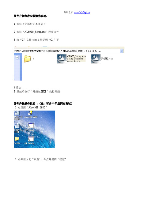
固件升级程序安装操作说明: 1 安装(完成后先不重启) 2 安装“AU6980_Setup.exe”程序文件 3 将“C”文件内的文件复到“C:”下
4 插入 U 盘,显示已插入后点“清空”。
数码之家
5 清空完成后点“更新”再退出 U 盘,
6 重新插入 U 盘,显示已插入后点“开始”
数码之家
7 显示绿色表示已量产 OK。
8 点“更新”,再退出 U 盘。操作结束
阿蛮歌霸!网络版点歌系统安装说明
阿蛮歌霸!网络版点歌系统安装说明一、安装概述网络版点歌系统,是通过局域网共享歌曲文件的一种点歌系统——歌曲文件存储于服务器并共享,然后包房电脑通过局域网访问服务器上的歌库。
网络版点歌系统的安装过程,大致需要4个步骤:1.在服务器上,安装“歌库管理器”;2.设置服务器:A.设置局域网;B.设置歌库共享;C.批量添加歌曲;D.批量添加歌星;3.在包房电脑上,安装“阿蛮歌霸点播器”;4.设置包房电脑:A.设置局域网;B.设置点播器;C.安装解码插件;服务器的操作系统,推荐使用Windows2003;包房电脑的操作系统,推荐使用WindowsXP。
二、具体步骤Step1. 在服务器上,安装“歌库管理器”网络版点歌系统的歌库,都是安装在服务器上的。
因此,为了便于管理,将“阿蛮歌霸!歌库管理器”程序,也安装在服务器上。
1)运行KtvSongMgr.exe,以安装“歌库管理器”。
2)指定程序安装的文件夹;然后,按照向导“下一步”完成安装。
【注意】后面的步骤2中,将对安装文件中的DataBase文件夹设置共享,请记住您的安装位置。
Step2. 设置服务器A.设置局域网熟悉局域网设置的读者,可以直接略过该部分。
1)设置服务器IP。
例如:IP=192.168.1.250、网关=255.255.255.0。
2)设置服务器的计算机名。
例如:计算名=VODSERVER;B.设置歌库共享1)共享Databas文件夹将安装文件夹中的DataBase文件夹,设置为共享。
共享名为DataBase,权限为“读取”与“共享”;2)共享歌曲文件夹将服务器上歌曲文件的根目录,设置为共享,权限为“只读”;3)更新曲库共享打开“歌库管理器”,选择“曲库共享”;然后在“曲库共享”窗口中,点“自动更新”;最后“确定”,保存设置。
C.批量添加歌曲1)打开“阿蛮歌霸!歌库管理器”→“曲库工具”→“歌曲工具”→“离线索引歌曲”。
2)指定需要索引的歌曲文件存放的位置。
- 1、下载文档前请自行甄别文档内容的完整性,平台不提供额外的编辑、内容补充、找答案等附加服务。
- 2、"仅部分预览"的文档,不可在线预览部分如存在完整性等问题,可反馈申请退款(可完整预览的文档不适用该条件!)。
- 3、如文档侵犯您的权益,请联系客服反馈,我们会尽快为您处理(人工客服工作时间:9:00-18:30)。
2 点弹出面的“设置”,再点弹出的“确定”
数码之家
3 选到“装置方式”,如需加密,则选“加密盘”,不加密则选“普通盘”,点“确定”
4 插入 U 盘,显示已插入后点“清空”。
数码之家
5 清空完成后点“更新”再退出 U 盘,
6 重新插入 U 盘,显示已插入后点“开始”
数码之家
7 示绿色表示已量产 OK。
8 点“更新”,再退出 U 盘。操作结束
数码之家
固件升级程序安装操作说明: 1 安装(完成后先不重启) 2 安装“AU6980_Setup.exe”程序文件 3 将“C”文件内的文件复到“C:”下
4 重启 5 重起后执行“升级包.EXE”执行升级
固件升级操作说明 : (注:可多个 U 盘同时测试) 1 点桌面“AlcorMP_6980”