3D3SV11.0升级内容说明彩页
先闻CAD工具箱-3d3s模块使用手册

先闻CAD工具箱3d3s辅助工具使用手册一、3d3s辅助绘图工具的描述3d3s辅助绘图工具是先闻CAD工具箱的增值模块之一,主要针对3D3S 空间结构(主要针对管桁架)开发的专用绘图辅助工具,让用户可以快速绘制大型复杂空间桁架结构的构件施工图,极大减少绘图工作量,缩短绘图时间,增加准确性。
注:使用该模块基本前提是结构空间模型要求十分准确,各节点定位明晰,杆件截面赋值明确。
本模块主要包含的操作步骤包括:1、加载3D3S数据文件。
注:目前要求3D3S版本为10.0,其他各版本可根据用户要求陆续开发。
2、模型校核。
(1)杆件查询。
(2)节点查询。
3、选择待绘制单元或构件。
4、绘制选定单元或构件。
以上步骤,要求用户按顺序执行,且互动准确。
二、安装方法用户下载解压后,安装至AutoCAD中,安装过程中需正确选择CAD版本。
三、系统需求:系统:Windows NT4/2000/2003/XP and Windows Vista/win7硬件:·Intel Pentium II 350MHz或以上, 或Athlon·64 MB RAM 或以上四、3D3S辅助绘图各步骤详细介绍1、加载3D3S数据文件:要求3D3S版本10.0。
输出3D3S文件按以下步骤。
(1)利用3D3S计算软件打开已经计算好的3D3S模型(模型几何数据准确,单位:mm),如下图所示:3D3S计算模型(2)选择菜单:结构编辑->数据输入、输出:将3D3S计算模型导出(3)选择菜单:导出->3D3S文件,并另存为.txt文件:保存3D3S计算模型的数据文件(4)利用先闻CAD工具箱3D3S辅助绘图模块,加载该模型文件(.txt):辅助绘图工具加载该数据文件(5)双击CAD屏幕,让模型充满显示区域。
注:此时模型为XY平面视角下显示,用户可利用空间视角查看空间模型。
数据文件加载成功,模型已读入该模块读入模型的功能,已经根据原模型的层信息读入,并把每个层重新定义为不同的颜色显示,这样能方便用户查看、选择。
PlayStation3 系统软件更新指南说明书

SYSTEMSOFTWARE AKTUALISIERENNähere Details dazu, wie Sie die Systemsoftware für das PlayStation ®3-System aktualisieren können, finden Sie unter oder in der Kurzanleitung des PS3™-Systems.SICHERHEITSHINWEISE• Diese Disc enthält Software für das PlayStation ®3-System. Verwenden Sie diese Disc niemals mit einem anderen System, da dieses sonst beschädigt werden könnte. • Diese Disc entspricht ausschließlich den Spezifikationen für PlayStation ®3 in den PAL-Ländern. Sie kann nicht auf Systemen mit anderen Spezifikationen für PlayStation ®3 verwendet werden. • Lesen Sie sich die PlayStation ®3-Bedienungsanleitung sorgfältig durch, um eine fehlerfreie Handhabung des Systems zu gewährleisten. • Legen Sie diese Disc immer mit der zu lesenden Seite nach unten in Ihr PlayStation ®3-System ein. • Berühren Sie nie die Oberfläche der Disc. Greifen Sie sie immer an den Seiten. • Vermeiden Sie Schmutz und Kratzer auf der Disc. Wenn Schmutz auf die Oberfläche kommt, wischen Sie sie vorsichtig mit einem weichen trockenen Tuch sauber. • Bewahren Sie die Disc niemals in der Nähe von Wärmequellen oder feuchter Umgebung auf und setzen Sie sie keinem direkten Sonnenlicht aus. • Verwenden Sie keine beschädigten oder deformierten Discs oder solche, die mit Klebstoff repariert wurden, da dies zu Fehlfunktionen führen kann.RAUBKOPIENDie unautorisierte Vervielfältigung des gesamten Produkts oder einzelner Teile und die unerlaubte Verwendung von eingetragenen Warenzeichen sind strafbare Handlungen. Raubkopien schädigen den Konsumenten und seriöse Entwickler, Publisher und Einzelhändler. Wenn Sie den Verdacht haben, dass es sich bei diesem Produkt um eine Raubkopie handelt, oder wenn Sie Informationen über unrechtmäßig kopierte Produkte haben, wenden Sie sich bitte an Ihren örtlichen Kundenservice. Die Nummer finden Sie auf der Rückseite dieses Software-Handbuchs.GESUNDHEITSWARNUNGSpielen Sie stets in einem gut beleuchteten Raum. Legen Sie eine Pause von 15 Minuten pro Spielstunde ein. Unterbrechen Sie das Spielen, wenn Schwindelgefühle, Übelkeit, Müdigkeit oder Kopfschmerzen auftreten. Bei einigen Personen kann es zu epileptischen Anfällen kommen, wenn sie bestimmten Lichtfrequenzen, flackernden Lichtquellen oder geometrischen Formen und Mustern ausgesetzt sind. Bestimmte Lichtfrequenzen in Fernsehbildschirm-Hintergründen oder bei Computerspielen können bei diesen Personen einen epileptischen Anfall auslösen. Befragen Sie Ihren Arzt, wenn Sie oder eines Ihrer Familienmitglieder an Epilepsie leiden, bevor Sie dieses Spiel spielen. Brechen Sie das Spiel sofort ab und suchen Sie einen Arzt auf, sollte eines der folgenden Symptome beim Spielen auftreten: Sehstörungen, Augen- und Muskelzucken, Bewusstseinsstörungen, Orientierungsverlust, unfreiwillige Bewegungen und Krämpfe.3-D-GESUNDHEITSWARNUNGManche Menschen verspüren Unbehagen (wie z. B. Belastung oder Erschöpfung der Augen oder Übelkeit), wenn sie sich 3-D-Videos ansehen oder stereoskopische 3-D-Videospiele auf 3-D-Fensehgeräten spielen. Wenn Sie solches Unbehagen verspüren, sollten Sie unverzüglich den Gebrauch des Fernsehgeräts einstellen, bis die Beschwerden nachlassen.Allgemein empfehlen wir Ihnen, Ihr PlayStation ®3-System nicht über längere Zeit ohne Unterbrechungen zu benutzen und pro Spielstunde eine Pause von 15 Minuten einzulegen. Beim Betrachten von 3-D-Videos oder dem Spielen von stereoskopischen 3-D-Videospielen variiert die Länge und Häufigkeit der notwendigen Pausen allerdings je nach Person. Bitte pausieren Sie lange genug, sodass eventuelle Beschwerden nachlassen können. Falls die Symptome bestehen bleiben, wenden Sie sich bitte an einen Arzt.Das Sehvermögen von kleinen Kindern (besonders den unter Sechsjährigen) ist noch in der Entwicklung begriffen. Fragen Sie Ihren Kinderarzt oder Augenarzt um Rat, bevor Sie kleinen Kindern erlauben, 3-D-Videos anzusehen oder stereoskopische 3-D-Videospiele zu spielen. Kleine Kinder sollten von Erwachsenen beaufsichtigt werden, um sicherzustellen, dass sie die obigen Empfehlungen einhalten.EUROPAWEITES SYSTEM PEGI (PAN EUROPEAN GAMES INFORMATION) ZUR VERGABE VON ALTERSEMPFEHLUNGENDas europaweite System PEGI zur Vergabe von Altersempfehlungen schützt Minderjährige vor Spielen, die für ihre Altersgruppe nicht geeignet sind.BITTE BEACHTEN SIE: Dies ist keine Richtlinie für den Schwierigkeitsgrad des Spiels. Besuchen Sie für weitere Informationen.PEGI besteht aus drei Einstufungskriterien, die es Eltern und anderen Käufern ermöglichen, eine sachkundige Auswahl, passend für das Alter deszukünftigen Spielers, zu treffen. Das erste Kriterium ist eine Alterseinstufung:Das zweite Kriterium der Altersempfehlung kann aus einem oder mehreren Inhaltssymbolen bestehen, die die Art des Spielinhalts anzeigen.Die Anzahl dieser Inhaltssymbole ist vom Spiel abhängig. Die Altersempfehlung des Spiels spiegelt die Intensität von dessen Inhalt wider.Es gibt die folgenden Inhaltssymbole:Das dritte Kriterium ist eine Kennzeichnung, die anzeigt, dass das Spiel online gespielt werden kann. Diese Kennzeichnung darf nur von Online-Spiele-Anbietern verwendet werden, die sich dazu verpflichten, gewisse Standards aufrechtzuerhalten. Diese Standards beinhalten den Schutzvon Minderjährigen in Online-Spielen.Besuchen Sie www.pegionline.eufür weitere Informationen.KINDER- UND JUGENDSCHUTZDieses Produkt besitzt verschiedene auf dem Inhalt der Software basierende Kinder- und Jugendschutzeinstufungen. Diese können Sie für das PlayStation ®3-System einstellen, um das Abspielen von Produkten zu verhindern, deren Kinder- und Jugendschutzeinstufung eine höhere als die eingestellte Altersfreigabe erfordert. Weitere Informationen finden Sie in der Bedienungsanleitung des PS3™-Systems.Dieses Produkt wurde mit dem …PEGI“-Einstufungssystem bewertet. Die …PEGI“-Einstufungssymbole und -Inhaltsbeschreibungen sind auf der Packung dargestellt (mit Ausnahme der Länder, in denen es eine gesetzliche Regelung gibt). Es besteht die folgende Beziehung zwischen dem …PEGI“-Einstufungssystem und den Kinder- und Jugendschutzeinstufungen:Aufgrund der unterschiedlichen Altersfreigabesysteme in den verschiedenen Ländern, in denen dieses Produkt verkauft wird, kann in seltenen Fällen die Kindersicherungsstufe dieses Produktes höher sein als die in Ihrem Land geltende Altersfreigabe. Sie müssen eventuell die Kindersicherungsstufe auf Ihrem PS3™-System zurücksetzen, um das Spielen zu ermöglichen.…PEGI“-ALTERSEINSTUFUNGSGRUPPEKINDER – UNDJUGENDSCHUTZEINSTUFUNG97532ALTERSGRUPPE Keine Jugendfreigabe Frei ab 16 Jahren Frei ab 12 Jahren Frei ab 6 Jahren Ohne AltersbeschränkungFor Help & Support please visit: or refer to the telephone list below. If your local telephone number is not shown, please visit for contact details.INFORMATIONEN ZUR ONLINE-EINRICHTUNGSTEUERUNGCREdITSCREdITSCREdITSCREdITSCREdITSCREdITSCREdITSCREdITSCREdITSCREdITSCREdITSCREdITSCREdITSCREdITSHollywood Chamber of Commerce.KUNdENdIENST-INFORMATIONEN。
3D3S11网架网壳模块手册

第三章 例题 ............................................................................................................................................. 37 3.1 螺栓球网架 .......................................................................................................................................... 37 3.2 焊接球网架 ........................................................................................................................................... 43 3.3 网架下部为橡胶支座带混凝土柱网架 ............................................................................................... 45 3.4 网架模块的加锥、及模型包络的功能例题 ....................................................................................... 49 3.5 网架模块加吊车、辅助孔以及基准孔拟合功能例题 ....................................................................... 51
SANSI 产品安装说明书

WARNING: RISK OF FIRE AND SHOCK. Do not connect the module 02 to any other circuits or outlets. CAUTION: RISK OF FIRE AND SHOCK. ONLY intended for use on 15 ampere branch circuits. CAUTION: RISK OF FIRE AND SHOCK. Do not install power supply cord 13 within wall cavity.
This Cable Kit is designed to fit into both interior and exterior walls constructed with:
Back Wall
Minimum Space into Wall: 3 in. Stud
Minimum Drywall Thickness: 1/2 in. (MAX: 1 in.)
swallowed. Before starting assembly, verify all parts are included and undamaged. If any parts are missing or damaged, do not return the damaged item to your dealer; contact Customer Service. Never use damaged parts!
13
Removal
a
Unplug power
b Turn screws to remove modules
Loosen ONLY enough to remove module.
3d3s入门教学说明

21
支座边界和单元释放
刚性约束、弹性约束、支座位移边界 斜边界 支座和刚节点
刚节点:各杆连接起来,相互之间不 能发生任何相对位移或转动的节点。 固定支座:支承结构的装置,限制结 构任何方向的移动或转动。
返回
22
菜单功能简介——荷载编辑(部分)
施加节点荷载 施加单元荷载 查询和删除荷载 组合
建模准备工作?分析目的?根据分析目的决定模型的繁简?概念分析?精确分析?节点全生成?结构特征?刚性柔性?线性非线性?施工过程决定分析方法?程序功能?选择合适的分析软件?选择合适的分析模块?设备能力?ansys需要1g空间?3d3s需要autocad2000或autocad2002支持
3D3S 通用钢结构分析和设计软件
菜单调用 软件缺省将调用3D3S定制菜单,当界面上仍 为acad菜单时,可使用menu 命令在3D3S安装 目录中调用。
6
3D3S坐标系统
●3D3S要求采用ACAD世界坐标系,并规定Z
的负方向为重力方向。
注意:必须理解ACAD中的用户坐标系和世 界坐标系的区别。
操作:如何将ACAD中的坐标系统从用户坐 标系转到世界坐标系
下一张
19
建立截面库
用途:选择工程中会用 到的截面类型,增 加新截面
重排 增加 删除 显示截面特性
返回
20
定义方位
i,j,k三点构成的平面确 定局部坐标1-2,按右手 螺旋法则确定3
为什么有无穷大? 为什么设负无穷大? 什么是绕1轴转角? 楔形单元放置参数(小
小大大) 特殊的方位设定
示\部分隐藏\取消附加信息显 示\全部显示 显示荷载 显示参数\显示颜色
下一张
15
总体信息\构件查询\总用钢量
维纳斯立体观察系统操作说明和维修手册说明书
E N G I N E E R I N GMantis Stereo Viewing SystemOperating InstructionsAndService ManualUse this manual only after assembling the Mantis Viewing system.After assembling the Mantis Stereo Viewing System you should be familiar with its various components. These instructions will help you become familiar with the operation and use of the Mantis as well as some of the available options. Also included in this manual is a more comprehensive maintenance, troubleshooting and service guide.NOTE: REFER TO THE MANTIS USER GUIDE AS REQUIRED1/Mantis/7/98CONTENTS Page1) System Diagrams (2)M antis Universal Boom Mount (3)M antis FX Bench Mount (4)1) The Basic Systems (5)1) Objective Specifications (7)1) Using the Mantis (9)T urning the Power “ON” (10)F ocusing (10)A djusting the Lighting .................................... (10)C hanging the Magnification (11)A djusting the Eye Spacing (11)5) Options (12)L ens Protective Covers (13)6)Maintenance (14)Lamp Replacement (15)Lens Cleaning (15)Moisture Control (15)Optical Path Alignment (15)Fan (15)7)Troubleshooting (16)Mantis has No Power (17)Optical View ............... (17)8)Service (18)C leaning the Mirrors (19)F an Replacement (20)R epairing Eye Spacing Adjustment (21)M irror Removal (22)9)Warranty (23)10) Information (25)SYSTEM DIAGRAMSSYSTEM DIAGRAMMANTIS UNIVERSAL BOOM MOUNTE N G I N E E R I N GDescription User Guide Des.Part No.1. Yaw Bolt Cover Cover Plate 187-A-00792. Yaw Bolt Assembly Yaw Spigot YB-A-0013. Anti-glare Shield Anti-glare Shield 187-B-00904. Adj. Friction Handle Height Friction Clamp HAN-05675. Table Mount Base Universal Mount 187-C-02586. C Clamp Assembly G ClampHDW-10927. Power Switch SWI-01228. Switch Cover 187-A-01119. Fan Cover Assembly 187-A-021110. Desiccant(10 pack)Desiccant CartridgeM00611. Grommet HDW-103012. Turret Assembly 187-A-020813. Filter Tray - Left 187-C-007614. Filter Tray - Right 187-C-007515. Lamp Diffuser 187-A-011516. Lamp Diffuser(Blue)187-A-0115A 17. Lamp, 12volt, 20wattLAM-13001241314151617101139128756MANTIS FX BENCH STANDVisi nE N G I N E E R I N GDescription User Guide Des.Part No.1. Yaw Bolt Cover Cover Plate 187-A-00792. Yaw Bolt Assembly Yaw Spigot YB-A-0013. Anti-glare Shield Anti-glare Shield187-B-00904. Focusing Thumbwheel 5. Focusing Platform 187-D-292*6. Surface Lighting Switch7. Substage Lighting Switch8. FX Base187-C-03109. Fan Cover Assembly 187-A-021110. Desiccant(10 pack)Desiccant CartridgeM00611. Grommet HDW-103012. Turret Assembly 187-A-020813. Filter Tray - Left 187-C-007614. Filter Tray - Right 187-C-007515. Lamp Diffuser 187-A-011516. Lamp Diffuser(Blue)187-A-0115A 17. Lamp, 12volt, 20wattLAM-1300*Requires Sub-Assembly187-B-3071231011121314151617956784SYSTEM DIAGRAMThe Basic Systems2) The Basic SystemsThe Mantis Stereo Viewing System is a powerful optical inspection system. The patented optical technology provides a bright, crystal clear overhead image in a fatigue free viewing environment. Long working distance offers ample room for rework and part rotation.Mantis systems are available in two versions. One version is the boom mount (refer to page 3 of this manual) which can be mounted on almost any table surface. This is good for general inspection, viewing and rework, especially in a production environment. The other version is the Mantis FX (refer to page 4 of this manual). This version has a portable stand that resembles a traditional microscope stand. This version is better suited to off-line inspection.Each Mantis system can be equipped with any two of the objective lenses listed below. It is common to use a lower magnification lens (such as 2X or 4X) for general inspection and a higher magnification lens (such as 8X or 10X) for closer inspection of possible defects.Mantis - Boom MountDescription Vision Engineering Inc. Part No.1) Mantis viewing head M0012) Mantis Boom Mount M003Mantis FX - Bench StandDescription Vision Engineering Inc. Part No.1) Mantis viewing head M0012) FX Bench Stand M002Objectives - For use with either systemDescription Vision Engineering Inc. Part No.1) 2X Magnification Lens M2222) 4X Magnification Lens M4443) 6X Magnification Lens M0044) 8X Magnification Lens M0085) 10X Magnification Lens M0096) 6X SLWD Magnification Lens M013The 6X SLWD magnification lens has a much longer working distance than the standard 6X magnification lens. It is specifically designed for rework applications.Objective Specifications 3)Objective SpecificationsThe Mantis objectives provide different levels of magnification ranging from 2X to 10X. As magnification changes, working distance (the distance between the objective lens and the subject when properly focused), field of view (the area of subject that is visible in the viewing screen at any one time) and depth of field (the maximum subject height variation that will remain in focus) also change. The chart below shows the characteristics of each lens.Lens Working Distance Field of View Depth of Field2X171 mm ~ 6.7 in.56 mm ~ 2.2 in. 25 mm ~ 1.0 in.4X 86 mm ~ 3.4 in.28 mm ~ 1.1 in. 11 mm ~ 0.4 in.6X 55 mm ~ 2.2 in.20 mm ~ 0.8 in. 5 mm ~ 0.2 in.6X SLWD112 mm ~ 4.4 in.20 mm ~ 0.8 in. 5 mm ~ 0.2 in.8X 41 mm ~ 1.6 in.15 mm ~ 0.6 in. 3 mm ~ 0.1 in.10X 41 mm ~ 1.6 in.12 mm ~ 0.5 in. 2.5 mm ~ 0.1 in.Using the Mantis 4) Using the MantisTurning the Power “ON”Boom Mount (refer to page 3 of this manual)There is one power switch for the Mantis boom mount system. It is located on the front panel of the vertical support column. Flip the switch to energize the Mantis illuminatorFX Bench Stand (refer to page 4 of this manual)There are three power switches for the Mantis FX bench stand system. The first is the main power switch. It is located on the back of the bench stand vertical support. When energized the switch is illuminated. The remaining power switches are on the front of the bench stand vertical support. The upper switch powers the main illuminator incorporated in the Mantis viewing head. The lower switch powers the substage illuminator built into the focusing platform.FocusingAll of the Mantis objective lenses (except 2X) are parfocal. This means that the image stays in focus when switching between objectives without re-focusing. For best results always focus with the highest magnification lens, then switch to the lower magnification.Boom Mount (refer to page 3 of this manual)To focus the boom mount Mantis system move the Mantis viewing head “UP” or “DOWN”. (Before moving the Mantis head always loosen the boom friction clamp lever located on the right side of the boom mount pivot). To facilitate focusing there are 4 plastic lugs located on the underside of the Mantis head. Hold one of the lugs between your thumb and index finger and gently move the head until proper focus is obtained. Tighten the boom friction clamp.FX Bench Stand (refer to page 4 of this manual)To focus the FX bench stand locate the focus adjustment wheel on the front, right hand corner of the bench stand base plate. Turning this wheel will move the focusing platform “UP” or “DOWN”. With a subject on the focusing platform look into the viewing screen and turn the focus adjustment wheel until a clear image is obtained.Adjusting the LightingThe main illuminator built into the Mantis viewing head features an adjustment to optimize lighting for different applications. The illumination adjustment is a horizontal disc on the right side of the Mantis viewing head. Rotate the disc while looking into the viewing screen until optimal lighting is achieved.4) Using the Mantis (con’t)Changing the Magnification (refer to pages 3 or 4 of this manual)Both Mantis systems use a turret assembly to allow the user to select between two different magnification levels. Objective lenses are screwed onto the threaded turret underneath the Mantis viewing head.After two objectives have been selected and screwed into place on the Mantis turret, they can be switched using the objective selection lever. The lever is located on the left side of the Mantis viewing head. The objective selection lever can be moved into two positions. Each position corresponds to a different objective lens being activated. Select the position that provides the magnification required for your application.Adjusting the Eye Spacing (IPD)The Mantis has an adjustment for different eye spacing. The Inter-pupilary Distance (IPD) must be adjusted to obtain a comfortable view. The IPD adjustment is located on the right side of the Mantis viewing head. While looking in the viewing screen rotate the adjustment knob (the left side optical path will move “LEFT” or “RIGHT”) until a comfortable view is achieved.Note: This adjustment is very important to comfortable and effective inspection. It must be re-adjusted for every individual using the Mantis.Options5) OptionsLens Protective coversAll mantis objectives can be fitted with a replaceable, clear plastic protective cap. These inexpensive caps protect the objective lens from damage and are especially useful when using the Mantis for rework operations. Choose from the chart below.Lens Vision Engineering Part No.2X, 4X, 6X, 8X M0106X SLWD M01610X M011Maintenance6)MaintenanceLamp Replacement (refer to pages 3 or 4 of this manual)Replace the lamps using the following procedure.1) Remove the Mantis viewing head by removing the Yaw Spigot nut.2) Turn the Mantis viewing head upside down.3) Remove the lamp cover (filter tray) by sliding it away from the Mantis head. Do not allow thediffuser lens to drop when removing the lamp covers.4) Pull the lamp out by holding it between your thumb and index finger.5) Replace lamp.6) Reassemble by reversing previous steps.Lens CleaningClean the objective lens using a lint free cloth. An anti-static cleaner may be used to reduce static charging.If frequent contamination is experienced it is recommended to use the optional Protective Lens Covers.Moisture Control (refer to pages 3 or 4 of this manual)The Mantis head is equipped with a blue desiccant cartridge for moisture control. This should be checked regularly. When the desiccant turns pink it is ready for replacement.To replace the cartridge remove the rubber plug under the Mantis viewing head, pull out the desiccant cartridge, replace and re-install the rubber plug.Replace with Desiccant 10 pack, Part No. M006.Optical Path AlignmentIt is a good idea to periodically check the Optical Path Alignment of the Mantis stereo view. Look into the viewing screen from a distance of 12”. The view will appear as two illuminated circles. These two circles must be horizontally aligned within 2/3 of their diameter of each other. Improper alignment will cause imaging problems.If the illuminated circles are out of alignment then they can be adjusted. Locate the large Phillips screw head on the back of the Mantis viewing head (this screw head is locked in place with black silicon). While still looking at the viewing screen from a 12” distance, adjust the screw until the two paths are in acceptable alignment.Fan (refer to pages 3 or 4 of this manual)Blow out the fan assembly with CLEAN, DRY AIR (up to 100 PSI) at least once a month to prevent excessive particulate build-up. This will maximize fan life.Troubleshooting7) TroubleshootingMantis has no powerIf the Mantis head has no power and the illuminator will not come “ON” then check the following items:•Is the Mantis power cord plugged in?•Is the wall outlet functioning properly and supplying sufficient voltage?•Is the fuse in the Mantis support column in good working condition?Optical ViewIf over time the optical view of the Mantis has degraded, check for the following:Are the objectives dirty or damaged?•Dirty or damaged lenses will cause an inferior image.Are both lighting lamps functioning properly?•Both lights must be working to supply sufficient light.Is the Eye Spacing control properly adjusted?•The eye spacing adjustment must be set correctly to obtain a comfortable view.Has the lighting adjustment been used to optimize the lighting?•Optimized lighting is important to maintaining a clear image.Have the Mirrors within the Mantis head become dirty?•Mirrors contaminated with particulate will impede image performance.Is the viewing screen dirty?•Clean the viewing screen regularly to prevent dirt build-up from degrading the image.Has the Optical Path alignment been checked?•Proper Optical path alignment will greatly improve viewing ease.Service 8) ServiceShould the Mantis stereo viewing system require service the unit may be returned to Vision Engineering Inc. Some of the simpler repair procedures are discussed here to prevent excessive downtime.Cleaning the mirrorsThe mirrors within the Mantis viewing head can be cleaned. These mirrors are very delicate and can only be blown off with clean, dry air. Never wipe the mirrors with any type of cloth. Required Tools:Small Phillips screwdriverMedium Phillips screwdriver (magnetic preferred)Work in a dust free environment1. Remove the Mantis viewing head from its support by removing the Yaw bolt.2. Rest the viewing head upside down (objective turret facing “UP”)3. Remove the two screws on the rear of the viewing head.4. Remove both filter trays to gain access to the lamps. Do not allow the diffuser lens to dropwhen removing the lamp covers.5. Remove the screw located in each lamp socket.6. The lower viewing head assembly (black lower section) should now be removable7. Turn the lower viewing head assembly over to prevent dust accumulation on the mirror.8. Without Touching the Mirrors, blow off mirrors with CLEAN, DRY AIR while holding unitupright. Ensure that any dust falls out of the viewing head.9. If any contaminant is on the beam splitter, it can be gently wiped with a soft cloth.10. Reassemble by reversing the disassembly instructions.8)Service (con’t)Fan ReplacementRequired Tools:Small Phillips screwdriverMedium Phillips screwdriverWork in a dust free environment1. Remove the objective lenses.2. Remove the Mantis viewing head from its support by removing the Yaw bolt.3. Rest the Mantis viewing head upside down (turret facing “UP”)4. Remove the three screws from the turret.5. Remove the two screws on the infinity lens.6. Remove the two screws holding the fan assembly in place.7. Remove the two screws on the rear of the Mantis viewing head.8. Remove both filter trays providing access to the lamps. Be careful not to allow the diffuserlens to drop when removing the filter tray.9. Remove the single screw in each lamp socket.10. The lower viewing head assembly (black lower section) now lifts off.11. Gently turn over the viewing head assembly to reduce the risk of the mirror collecting dust.12. Disconnect fan wires from P.C. board and remove old fan. Pay close attention to the wireconnection orientation on the P.C. board.13. Install new fan. Feed new fan wires through grommet one at a time. Connect the wires tothe P.C. board being careful to follow the same orientation as the prior fan.14. Reassemble by reversing disassembly steps.8)Service (con’t)Repairing Eye Spacing Control (IPD)Required Tools:Small Phillips screwdriverMedium Phillips screwdriver (magnetic preferred)Work in a dust free environment1. Remove the magnification objectives2. Remove the Mantis viewing head from its support by removing the Yaw bolt.3. Remove the eye spacing adjustment knob.4. Rest the Mantis head upside down (turret facing “UP”).5. Remove the two screws on the rear of the viewing head.6. Remove both filter trays providing access to the lamps. Be careful not to allow the diffuserlens to drop when removing filter tray.7. Remove the single screw from each lamp socket.8. The lower viewing head assembly (lower black section) can now be removed.9. Gently turn over the viewing head assembly to reduce the chance of dust collecting on themirror.10. Without Touching the Mirrors, replace the detached pin through the viewing head and intothe narrow groove on the eye spacing control knob.11. If necessary, blow off the mirrors with CLEAN, DRY AIR while holding the unit upright.Ensure that any dust falls out of the viewing head.12. Reassemble by reversing the disassembly steps.8)Service (con’t)Remove Mirror from Mantis HeadIn the event that a mirror become dislodged within the Mantis viewing head it may be possible to reattach it by following these steps. If a repair cannot be made then follow these steps toremove the loose mirror. Removing the loose mirror will prevent any internal damage during shipping when returning the unit for service. The mirror can now be packed separately and both units sent back to the factory for service.Required Tools:Small Phillips head screwdriverMedium Phillips head screwdriver (magnetic preferred)Work in a dust free environment1. Remove the Mantis viewing head from its support by removing the Yaw bolt.2. Rest the viewing head upside down (turret facing “UP”).3. Remove the two screws on the rear of the viewing head.4. Remove both filter trays providing access to the lamps. Be careful not to let the diffuser lensdrop when removing the filter trays.5. Remove the single screw in each lamp socket.6. The lower viewing head assembly (lower black section) can now be removed.7. Without Touching the Mirror, remove the mirror or reattach if required.8. Reassemble by reversing the disassembly steps.Warranty9) WarrantyThis product is warranted to be free from defects in material and workmanship for a period of one year from the date of invoice to the original purchaser.If, during the warranty period the product is found to be defective, it will be repaired or replaced at facilities of Vision Engineering Inc. or elsewhere, all at the option of Vision Engineering Inc. However, Vision Engineering Inc. reserves the right to refund the purchase price if it is unable to provide replacement, and repair is not commercially practicable or cannot be timely made. Parts not of Vision Engineering Inc. manufacture carry only the warranty of their manufacturer. Expendable components such as lamps and fuses carry no warranty.This warranty does not cover damage caused in transit, damage caused by misuse, neglect, or carelessness, or damage resulting from either improper servicing or modification by other than Vision Engineering Inc. approved service personnel. Further this warranty does not cover any routine maintenance work which is reasonably expected to be performed by the purchaser.No responsibility is assumed for unsatisfactory operating performance due to environmental conditions such as humidity, dust, corrosive chemicals, deposition of oil or other foreign matter, spillage, or other conditions beyond the control of Vision Engineering Inc..Except as stated herein, Vision Engineering Inc. MAKES NO OTHER WARRANTIES, EXPRESS OR IMPLIED BY LAW, WHETHER OR MERCHANTABILITY, FITNESS FOR A PARTICULAR PURPOSE OR OTHERWISE. Further, Vision Engineering Inc. shall not under any circumstances be liable for incidental, consequential or other damages.Information10) InformationVision Engineering Inc. is committed to providing top quality optical inspection systems. We employ a staff of trained Sales and Service engineers and have a network of Authorized distributors to assist you. Please call whenever you have questions.For additional information contact your local Vision Engineering Distributor or call:Corporate Headquarters Western Region Sales Office Vision Engineering Inc.Vision Engineering Inc.570 Danbury Road745 W. Taft AvenueNew Milford, CT 06776Orange, CA 92865Phone: (860) 355-3776Phone: (714) 974-6966。
桑德斯3D打印机Model X材料最佳实践指南说明书

Version 1.1,February 2022Model X Material Best PracticeManufacturer:EnvisionTEC US LLCA Desktop Metal Company15162 S. Commerce Dr.Dearborn,Table of ContentsAbout Model X (3)Identification (3)Applicable Printers (3)Getting Started (4)Primary Supplies (4)Capture Patient Data (4)Design Models for Model X (5)Software (6)Orient Models Envision One RP Software (6)Support Models Envision One RP Software (6)Print Preparation (7)Mix Material (7)Fill Material Tray (7)Print with Model X Material (7)Post-Processing (8)Clean Printed Models (8)Dry Models (9)Post Cure Printed Models (9)About Model XIdentificationModel X with its 50-micron build layer allows for exceptionally detailed crowns, bridges with removable dies, implant cases and diagnostic and orthodontic models.This technical guide details the best practices for preparing models, post-processing, and finishing. Applicable PrintersThis material is tested and approved for the following printers:•Einstein™•Envision One cDLM•D4K ProGetting StartedPrimary SuppliesThe following supplies are required to print Model X material:•99% isopropyl alcohol (IPA).•Air compressor.•Cone-shaped paint filter, Starter Kit item.•Curing unit: Otoflash, SAP Part # ACC-00-0007, or PCA 4000 SAP Part # ACC-06-1000•Disposable aluminum loaf pan.•Dual Motion Bottle Roller, SAP Part # ACC-26-1000 (110V) and ACC-26-1000 (220V).•Nitrile gloves.•Paint scraper, Starter Kit item.•Paper towels.•Plastic funnel.•Rubber spatula, Starter Kit item.•Spray bottle with 99% IPA.•Snips, precision blade, or similar tool.•Storage container for material, sealable and opaque.•Washing unit: PWA 2000, SAP # ACC-22-2000.Capture Patient DataA digital impression can be accomplished with a handheld intraoral scanner and CBCT scan, or with a traditional impression and a desktop box scanner.Envision One RP Software is compatible with the universal .STL file format and is thus compatible with almost all dental CAD and model design software as well as digital design services. Models may be designed in-house or outsourced to a design partner.Design Models for Model XHollow dental models printed in Model X must have a minimum wall thickness of 3 mm, Fig. 2.It is recommended to add channels or drainage holes to hollow models. This allows uncured material to drain from the hollow feature during the printing process.SoftwareOrient Models Envision One RP SoftwareOrient models in Envision One RP Software with the flat base side down, parallel with the build platform.•Spacing: place models a minimum of 1.5 mm apart.•Level at build platform: place unsupported models 0 mm from the build platform. Place supported models 4 mm from the build platform.•Resolution: 50 µm Z resolution.Support Models Envision One RP SoftwareSome approved applications require supports. Always use the Model X.ini support file for supports –•Minimum support base: 1.0 mm•Minimum contact tip: 0.45 mm•Minimum support beam height: 4.0 mmPrint PreparationMix MaterialModel X material must be mixed in the material bottle prior to use:1.Place the sealed material bottle on the Dual Motion Bottle Roller for a minimum of 60 minutes.2.Wait for bubbles to subside before filling the material tray.3.Mix material in the material tray gently with the rubber spatula from the Starter Kit before eachprint. The material should be a uniform color.Ensure there are no small cured particles in the material. If found, then the material must be filtered using the plastic funnel, cone-shaped paint filter, and a spare material bottle. See the Knowledge Base for filtering instructions.Fill Material TrayDo not overfill the material tray. Overfilling can cause the material to overflow when the build platform moves down at the start of the print job.To add more material to the printer, carefully pour material into the material tray between prints. Adding material while the print is paused, or during a print, will cause a small shift line in the model.See the Knowledge Base for instructions adding material.Print with Model X MaterialTo start the print, follow instructions in the printer’s User Manual.To remove the models from the build platform after the print is complete, follow instructions in the printer’s User Manual. See the Knowledge Base for the latest User Manual.Post-ProcessingClean Printed ModelsThe PWA 2000 is the recommended parts washer, Fig. 4. Always wear gloves when handling uncured material and alcohol.Important:Do not expose Model X to alcohol for longer than 5 minutes. Excessexposure to alcohol may cause discoloration and warping.Clean models the PWA 2000:1.Open the washing compartment lid.2.Lift the handle to raise the interior grate to the highest position.4.Place the model on the grate and gently lower the handle to submerge the model in 99% IPA.5.Close the washing compartment lid and lock in place.6.Plug in the power cable to turn on the PWA-2000.ing the touchscreen, select the High washing program. Set the timer to 00:03:00, or 3 minutes.Press Start.→The PWA 2000 will immediately begin the set washing cycle.8.Remove the model as soon as the program is complete.9.Spray the models with the spray bottle filled with 99% IPA.e compressed air to remove all IPA from the surface of the model as soon as possible.Dry ModelsModels must be completely dry before post curing –1.Place the models on a clean paper towel lined surface.2.Air dry in ambient room temperature / humidity for 10 min.Post Cure Printed ModelsCure the models using the following method:Otoflash:2 cycles for 500 flashes, flip models between cycles.See the Knowledge Base for instructions setting an Otoflash curing cycle.PCA 4000:1 Minute - 20° C - 100% Power.See the Knowledge Base for instructions setting a PCA 4000 curing cycle.Place models into the curing unit with as much space between models as possible. Models should never touch one another while curing. Let models cool completely before handling them or starting the next cycle. Flip models between cycles for an even cure.Important: Desktop Health does not support third-party curing units.。
3D3SV13升级功能点
第 7.2.18 条
新增抗震设计
5 锚栓面积 时锚栓最小面
第 3.4.3 条第 3 款
--
积构造要求
11
v13 升级功能点
4 13202 混凝土多高层
4.1 全新的设计流程,支持按标准层快捷编辑模型,保证层间位移等总体信息的正确输出。 同时,支持在在组装模型中添加复杂空间结构。
4.2 更新《高层民用建筑钢结构技术规程》JGJ99-2015。 4.3 增加《钢管混凝土结构技术规范》GB50936-2014 第五章、第六章,圆管混凝土构件、矩
13
v13 升级功能点
梁柱节点 叠合板
形钢管混凝土结构的验算。 4.4 增加墙、墙组的计算和验算功能。 4.5 实现新增截面 3 种十字形钢截面的验算功能,5 种型钢混凝土截面的设计功能。
12
5 13202A PC-装配式结构
v13 升级功能点
5.1 新增混凝土装配式节点设计工具箱,通过可视化,参数化建模方式,生成装配式整体模 型,所有部件实体建模,可检查钢筋碰撞,真实计算截面有效高度,支持梁柱节点、柱 与基础节点、柱与地下室顶板节点、主次梁节点、叠合楼板节点,外挂墙板节点,预埋 件节点等,节点包含预制柱连接,梁柱核心区计算,梁端结合面计算等功能。
新增局部屈曲承压计算等。
3.4 节点设计 新规范改进了节点域转动刚度验算的公式,增加了锚栓抗剪计算,增加了锚栓锚固
长度和锚栓面积的最小构造要求。
节点设计比较
序 节点计算
号
项
内容对比
门式刚架轻型房屋钢结构 CECS102-2002(2012 年
技术规范(GB51022-2015)
版)
1 钢材强度
f, fv
9
Flow-3D V11.1版本的新功能介绍
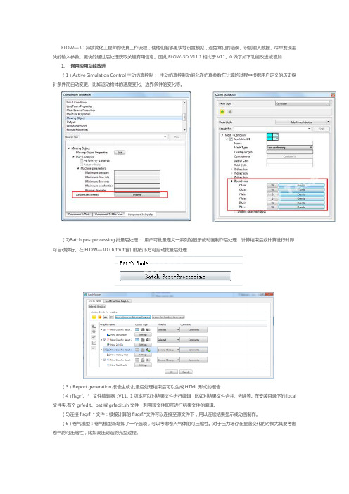
FLOW—3D持续简化工程师的仿真工作流程,使他们能够更快地设置模拟,避免常见的错误、识别输入数据、尽早发现丢失的输入参数、更快的通过后处理获取关键有用信息。
因此,FLOW-3D V11.1相比于V11。
0做了如下功能改进或增加:1。
通用应用功能改进(1)Active Simulation Control主动仿真控制:主动仿真控制功能允许仿真参数在计算的过程中根据用户定义的历史探针条件而自动变更。
比如运动物体的速度变化、边界条件的变化等。
(2)Batch postprocessing批量后处理:用户可批量定义一系列的显示或动画制作后处理,计算结束后或计算进行时即可自动执行。
在FLOW—3D Output窗口的右下方可启动批量后处理.(3)Report generation报告生成:批量后处理结束后可以生成HTML形式的报告.(4)flsgrf。
*文件编辑器:V11。
1版本可以对结果文件进行编辑,比如对结果文件合并、去除等。
在安装目录下的local 文件夹,有个grfedit。
bat或grfedit.sh文件,利用该文件即可进行结果文件的编辑。
(5)连接flsgrf.*文件:续接计算的flsgrf.*文件可以连接至源文件下,用以连续结果显示或动画制作。
(6)卷气模型:卷气模型新增加了一个选项,可以考虑卷入气体的可压缩性。
对于压力场存在显著变化的时候尤其要考虑卷气的可压缩性,比如高压铸造的充型过程。
(7)Cavitation model空化模型:V11.1版本中的空化模型能更好地解决到湍流引起的空化问题.增加了基于经验关系式空化核选项,补充现有的恒定速率方法.(8)固体组件燃烧模型:新增固体组件燃烧模型,用于火箭等航天器固体燃料推进剂的模拟,燃烧反应速率可以是当地气体压力的函数.(9)双流体相变模型:过冷模型已经添加到双流体气液流动当中,通过定义过冷温度常数,气体温度可以在冷凝发生前下降到饱和温度点以下.(10)液体/壁面接触时间:V11。
3D3SV12.1版软件功能说明
3D3SV12.1新规范版本设计软件改进说明2015年3月目录1.基本模块 (3)1.1 推出64位3D3S (3)1.2 增加结构类型选项 (3)1.3增加支座显示数值项 (3)1.4增加构件直接定义为连接单元项 (3)1.5可直接编辑的荷载说明 (4)1.6更加人性化的最小夹角查询功能 (4)1.7由用户选择的参考端 (4)1.8增加标注截面序号项 (5)1.9增加任意曲面方位拟合功能 (5)1.10不断扩充的截面库 (6)1.11比例缩放支持分数的输入 (8)1.12更加人性化的计算书输出 (8)1.13导出为revit文本格式文件 (8)1.14导出为Sap2000(V15)文本格式文件 (8)2. 多高层设计系统 (9)2.1改进结构总信息窗口 (9)2.2不断完善的总体信息查询 (10)2.3增加P-Dalta力来源各自工况或组合项 (10)2.4增加P-Dalta效应缺陷考虑项 (10)2.5增加定义质量源中质量集中于楼层平面项 (11)3.网架网壳结构设计系统 (12)3.1增加自定义配件库 (12)3.2 可控的锥头、封板、套筒强度 (12)3.3 灵活的封板锥头焊缝间隙 (12)3.4 增加用户控制螺栓球大小的碰撞提示命令 (13)3.5 完善支座节点参数默认值,并保存上次修改值 (13)3.6完善显示小立柱定义及显示功能 (13)3.7人性化的螺栓节点设计 (13)3.8 调整焊接球节点设计参数默认值 (14)3.8 更加精准的焊接球材料表 (14)3.9 增加不规则网架尺寸按比例输入功能 (14)3.10 改进网架结构带颜色显示实体的功能。
(15)3.11 验算结果增加加劲肋结果显示项 (15)4.钢管桁架结构设计系统 (16)4.1不断完善的桁架快捷建模 (16)4.2增加支座节点定义功能 (16)5.变电构架设计系统 (17)5.1增加单管柱中柱节点设计及出图 (17)5.2增加柱与有偏移横梁的中部连接节点 (17)5.3完善高架短柱柱顶节点设计,新增加劲肋参数设置 (17)5.4 完善人字柱变电站图纸,更贴合设计人员绘图习惯 (17)1.基本模块1.1 推出64位3D3S3D3SV12.1支持xp系统,32位、64位win7系统以及win8系统等多种计算机系统。
3D3SV11.0升级内容说明彩页

3D3SV11.0版软件功能介绍任意空间结构设计模块 1. 3D3S 软件AutoCAD 平台由AutoCAD2004~2006升级为AutoCAD2007~ 2009; 2. 内置规范完全升级为新规范,包括抗震规范(GB50011-2010)、网格规范(JGJ7-2010)、混凝土结构设计规范(GB50010-2010)、高层建筑混凝土结构技术规程(JGJ3-2010);3. 增加铝合金结构设计规范(GB50429-2007)进行构件验算的功能;4. 增加完善了模型数据接口功能,支持的格式包括IFC 格式、SAP2000、ETABS 、MIDAS 、ANSYS 、ABAQUS 、STAAD ;5. 新增按照截面插入点设置杆件偏心的功能;通过调整截面插入点来对梁上表面进行对齐操作数据转换所支持的格式8.新增构件1轴方位调整的功能,可用于对不等肢角钢等非对称截面方位进行调整;6.新增将模型内力图、位移图等3D3S实时显示效果保存为dwg文件的功能;7.增加将结构内力、位移、反力和振型输出为excel表格的功能;得到Excel表格9.验算结果查询对话框对于验算结果信息的显示更为详尽,包括验算过程中的塑性开展系数、稳定参数等;10.新增可允许产生部分位移的支座设置功能;通过输入支座的允许位移值乱来控制支座的滑移梁,当位移值小于允许位移时则支座不产生反力。
11.新增节点局部坐标,可以轻松处理斜方向支座的问题;节点局部坐标设置对话框通过调整节点局部坐标来实现对于结构径向及切向的约束:12.新增在任意结构中布置悬挂吊车的功能;任意悬挂吊车设置对话框通过选择节点可为在任意结构中布置悬挂吊车:14.新增模型中显示构件计算长度的功能;在验算结果显示中勾选显示数值来显示计算长度:13.新增构件按照优选分组进行显示的功能;通过选择优选分组所在的层来显示同组构件:15.新增按导荷载作用范围对构件显示调整功能;对于已经设置了导荷载的杆件可以直接进行复制、显示等操作,同时还可以对荷载所作用的范围进行复制来的到新的作用范围相同的荷载:仅显示作用杆件17. 改进了彩色云图图标色条的背景颜色,保证与CAD 的背景颜色一致,便于输出方便打印的图像;16. 新增在部分杆件或节点上显示荷载的功能;调整后的位移及内力云图标色条的背景颜色将自动保持与CAD 背景颜色一致。
3D3S10.0升版通知
3D3S10.0升版通知感谢各位用户多年来对3D3S软件的支持。
3D3S v10.0在V9.0的基础上进一步得到完善和加强。
与9.0相比,本次升版更新内容如下:建模基本功能V10.0版的界面更为友好,操作更加便捷、导荷载更为方便,大大提高了模型编辑操作的效率。
1. 新增裹冰风荷载增大系数;2. 新增特殊组合输入输出文本功能;3. 新增导荷载参数按序号分开定义及导风荷载内部参考点显示功能;4. 新增沿某一方向(如X向)Scale功能;5. 改进了导出为sap模型时,将分层信息转换为sap的分组信息;6. 新增读入Sap2000,ETABS,及Midas 模型的功能;7. 新增国标GBT 6723 冷弯薄壁型钢截面库的截面尺寸;内力分析功能V10.0修正了V9版本中的一些非线性分析的荷载处理和收敛性能的问题,从而大大提高了大型钢结构非线性分析的效率。
1. 新增与硬盘交换的大型求解器,可以求解百万自由度的大型工程;2. 改进了振型求解器的性能,振型求解更加迅速;3. 新增三节点纤维梁单元,可以分析截面线性变化的构建;注:功能1和功能3将在12月份发布。
设计验算功能V10.0完善了计算长度的搜索的搜索功能 能正确搜索到曲梁的计算长度。
修正了原本柱计算长度的搜索的错误。
能够正确判断打断后的楔形构件的两端截面特性和内力。
对于两端有支座约束的构件可以正确判断其计算长度。
增加了钢结构验算输出结果: 计算长度; 验算用的材料强度; 验算局部稳定所用的规范条文及限值; 验算长细比时所取的长细比限值。
新增自定义材料设计强度的修改功能,若用户在选择了某一牌号的钢材料,如Q235,又修改了其屈服强度,则材料的设计强度也会相应发生改变。
对于铝合金规范的嵌入工作,目前正在完善中,完成后将及时提供给v10.0用户。
新增友好的帮助系统全新打造的帮助系统,可以完成与当前操作对话框相关的帮助信息的自动查找,并可以按关键字查找以及设置书签。
A3S3 固件升级记录说明书

A3S3固件更新记录发布日期:2022-01-15固件版本:V2.7数据版本:V2.0修改内容:•修改无接收机信号的判定条件,陀螺仪只会在副翼、升降和方向三个通道都没有输入信号时才进入接收机信号超时状态;•修改所有PWM输入捕获通道的有效脉宽范围为500~2500uS,超出该限制的输入信号将被陀螺仪忽略,舵机停留在当前位置不动;•修改所有输出通道的PWM最大脉宽范围为800~2220uS。
注意事项:•下载最新的A3 Configurator集成配置软件完成在线固件升级和调参;•此次升级不会改变陀螺仪的当前设置,但还是建议您在升级完成后确认设置是否正确;•设置卡不需要升级,您可以继续使用设置F/W V4.0或设置卡X F/W V1.0进行调参;•A3 Super 3使用说明书V2.0同样适用于新固件V2.7。
发布日期:2021-08-06固件版本:V2.6数据版本:V2.0修改内容:修复了V2.5的已知问题。
注意事项:•下载最新的A3 Configurator集成配置软件完成在线固件升级和调参;•此次升级不会改变陀螺仪的当前设置,但还是建议您在升级完成后确认设置是否正确;•设置卡不需要升级,您可以继续使用设置F/W V4.0或设置卡X F/W V1.0进行调参;•A3 Super 3使用说明书V2.0同样适用于新固件V2.6。
发布日期:2021-04-10固件版本:V2.5数据版本:V2.0修改内容:•改进姿态算法,修复之前固件在自动平衡模式或教练模式下飞行时偶尔出现的飞机俯冲问题。
为获得更好的性能,新固件要求更精确的陀螺仪开机校准,在通电后请保持飞机静止直到初始化完成。
当检测到轻微移动时,蓝灯会保持常亮,直至飞机不再移动校准才会重新开始。
尽管如此,开机初始化阶段并不需要将飞机水平放置;•为直连通道[A2]和[E2]增加失控保护功能,当[A2]或[E2]被用作直连通道时,如果飞行过程中来自接收机的信号丢失,舵机将自动回到它们上电时的初始位置上,从而实现失控保护。
HP 3D High Reusability PA 11 Ductile材料说明书

HP 3D High Reusability PA 11Ductile,1 quality partsProduce strong, ductile,1 functional parts• Thermoplastic material delivering optimal mechanicalproperties.• Provides excellent chemical resistance2 and enhancedelongation-at-break.1• Impact resistance and ductility1 for prostheses, insoles,sports goods, snap fits, living hinges, and more.Minimize waste with a renewable raw material3• Renewable raw material from vegetable castor oil (reducedenvironmental impact).3• Minimize waste—reuse surplus powder batch after batchand get functional parts, no throwing away anymore.4• Get consistent performance while achieving 70% surpluspowder reusability.5• Optimize cost and part quality—cost-efficient material withindustry-leading surplus powder reusability.4Engineered for HP Multi Jet Fusion technology• Designed for production of functional and final parts acrossa variety of industries.• Provides the best balance between performance andreusability.6• Easy-to-process material enables high productivity and lesswaste.7• Engineered to reliably produce final parts and functionalprototypes with fine detail, dimensional accuracy.3D data courtesy of NACARFor more information, please visit866-277-8778This is an HP Indigo digital print.© Copyright 2017, 2018 HP Development Company, L.P.Nothing herein should be construed as constituting an additional warranty. The only warranties for HP products and services are set forth in the express warranty statements accompanying such products and services and/or in a written agreement between you and HP for such HP products and services. HP believes that the information herein is correct as of the date of its publication, however, HP EXPRESSLY DISCLAIMS ANY REPRESENTATIONS AND WARRANTIES OF ANY KIND, WHETHER EXPRESS OR IMPLIED, AS TO THE ACCURACY, COMPLETENESS, NON-INFRINGEMENT, MERCHANTABILITY AND/OR FITNESS FOR A PARTICULAR PURPOSE (EVEN IF HP IS AWARE OF SUCH PURPOSE) WITH RESPECT TO ANY INFORMATION PPROVIDED. HP shall not be liable for technical or editorial errors or omissions contained herein and the information herein is subject to change without notice. In no event shall HP be liable for damages or losses of any kind or nature that result from the use of or reliance upon this information. The HP Jet Fusion 3D Materials have not been designed, manufactured or tested by HP for compliance with legal requirements for 3D printed parts and their uses and recipients are responsible for making their own determination as to the suitability of HP Jet Fusion 3D Materials for their purposes and uses.4AA7-0715ENE, November 20181. Testing according to ASTM D638, ASTM D256, and ASTM D648 using HDT at different loads with a 3Dscanner for dimensional accuracy. Testing monitored using statistical process controls.2. Tested with diluted alkalies, concentrated alkalies, chlorine salts, alcohol, ester, ethers, ketones, aliphatichydrocarbons, unleaded petrol, motor oil, aromatic hydrocarbons, toluene, and DOT 3 brake fluid.3. HP 3D High Reusability PA 11 powder is made with 100% renewable carbon content derived from castorplants grown without GMOs in arid areas that do not compete with food crops. HP 3D High Reusability PA 11 is made using renewable sources, and may be made together with certain non-renewable sources. A renewable resource is a natural organic resource that can be renewed at the same speed in which it is consumed. Renewable stands for the number of carbon atoms in the chain coming from renewable sources (in this case, castor seeds) according to ASTM D6866.4. Based on using recommended packing densities and compared to selective laser sintering (SLS)technology, offers excellent reusability without sacrificing mechanical performance. Tested according to ASTM D638, ASTM D256, ASTM D790, and ASTM D648 and using a 3D scanner for dimensional accuracy. Testing monitored using statistical process controls.5. HP Jet Fusion 3D Printing Solutions using HP 3D High Reusability PA 11 provide 70% post-productionsurplus powder reusability, producing functional parts batch after batch. For testing, material is aged in real printing conditions and powder is tracked by generations (worst case for recyclability). Parts are then made from each generation and tested for mechanical properties and accuracy.6. Compared to selective laser sintering (SLS) technology. Providing an elongation at break XY of 50%with 70% post-production surplus power reusability according to the ASTM D638 test method. For testing, material is aged in real printing conditions and powder is tracked by generations (worst case for recyclability). Parts are then made from each generation and tested for mechanical properties and accuracy.7. Easier to process than standard HP 3D High Reusability PA 12, providing proper fusing along with goodspreadability and compatibility due to its small particle size.8. The following technical information should be considered representative of averages or typical values andshould not be used for specification purposes. These values are with FW TATDAG_15_18_11.69 and have been obtained from a sample of specimens printed in plots with 6% packing density. Separation between specimens in the plot was 10 mm. Modulus has been calculated using the slope of the regression linebetween 0.05% and 0.25% strain measured with an automatic extensometer during the entire test. Cross-section dimension obtained using a micrometer with round ends. Conditioning according to ASTM D618 Procedure A: 48 hours after printing and unpacking of the parts at 23°C/73°F and 50% RH. Orientations defined according to ASTM F2971.9. Test results realized under the ASTM D638 with a test rate of 10 mm/min, specimens type V.10. Test results realized under ASTM D790 Procedure B at a test rate of 13.55 mm/min.11.Based on HP internal testing, June 2017, HP 3D600 Fusing and Detailing Agents and HP 3D High Reusability PA 11 powder meet USP Class I-VI and US FDA's guidance for Intact Skin Surface Devices. Tested according to USP Class I-VI including irritation, acute systemic toxicity, and implantation; cytotoxicity per ISO 10993-5, Biological evaluation of medical devices–part 5: Tests for in vitro cytotoxicity; and sensitization per ISO 10993-10, Biological evaluation of medical devices–Part 10: Tests for irritation and skin sensitization. It is the responsibility of the customer to determine that its use of the fusing and detailing agents and powder is safe and technically suitable to the intended applications and consistent with the relevantregulatory requirements (including FDA requirements) applicable to the customer’s final product. For more information, see /go/biocompatibilitycertificate/PA11.12. Available in the second half of 2018.13. Liters refers to the materials container size and not the actual materials volume. Materials are measured in kilograms.14. The HP powder and agents do not meet the criteria for classification as hazardous according to Regulation (EC) 1272/2008 as amended.15.Compared to manual print retrieval process used by other powder-based technologies. The term “cleaner” does not refer to any indoor air quality requirements and/or consider related air quality regulations or testing that may be applicable.16.Compared to PA 11 materials available as of June, 2017. HP Jet Fusion 3D Printing Solutions using HP 3D High Reusability PA 11 provide 70% post-production surplus powder reusability, producing functional parts batch after batch.Technical specifications8Ordering informationCategoryMeasurement ValueMethodGeneral propertiesPowder melting point (DSC)202 °C/396 °F ASTM D3418Particle size54 μmASTM D3451Bulk density of powder 0.48 g/cm3/0.017 lb/in3ASTM D1895Density of parts1.05 g/cm3/0.038 lb/in3ASTM D792Mechanical properties Tensile strength, max load,9 XY, XZ, YX, YZ52 MPa/7542 psi ASTM D638Tensile strength, max load,9 ZX, ZY 52 MPa/7542 psi ASTM D638Tensile modulus,9 XY, XZ, YX, YZ 1800 MPa/261 ksi ASTM D638Tensile modulus,9 ZX, ZY1800 MPa/261 ksi ASTM D638Elongation at break,9 XY, XZ, YX, YZ 50%ASTM D638Elongation at break,9 ZX, ZY35%ASTM D638Flexural strength (@ 5%),10 XY, XZ, YX, YZ, ZX, ZY 70 MPa/10150 psi ASTM D790Flexural modulus,10 XY, XZ, YX, YZ, ZX, ZY1800 MPa/261 ksi ASTM D790Izod impact notched (@ 3.2 mm, 23°C), XY, XZ, YX, YZ 5 kJ/m2ASTM D256 Test Method A Izod impact notched (@ 3.2 mm, 23°C), ZX, ZY 4.5 kJ/m2ASTM D256 Test Method A Shore Hardness D, XY, XZ, YX, YZ, ZX, ZY80ASTM D2240Thermal properties Heat deflection temperature (@ 0.45 MPa, 66 psi), XY, XZ, YX, YZ, ZX, ZY185 °C/365 °F ASTM D648 Test Method A Heat deflection temperature (@ 1.82 MPa, 264 psi), XY, XZ, YX, YZ, ZX, ZY54 °C/129 °F ASTM D648 Test Method AReusability Refresh ratio for stable performance 30%Recommended environmental conditions Recommended relative humidity 50-70% RHCertifications USP Class I-VI and US FDA guidance for Intact Skin Surface Devices 11For more information, please visit 866-277-8778。
3D3S Design V2020快速安装说明
3D同济D3S快速大学3D3S 软S De 速安软件研发中esig 安装中心|上海同gn V 装说同磊土木工V20说明工程技术有限020 限公司注意:3D3S* 请确* 请确* 请确* 请确为确保安装软件锁外形 3D3S 32位/ 3D3S 支持6确保您的机器确保您在安装确保您的客户确保您的客户装成功,请形图: Sense4单Design V264位、win Design V264位);其器的USB 接装软件及硬户端电脑可户端电脑上前请认真阅读单机锁 020软件锁dows8 32位020可兼容其中“变电构接口可以正常硬件锁驱动可以通过网上的所有杀3D3S 安装说 锁支持的操作/64位、wi 容的平台:支构架”模块常工作。
时具有计算络正常访问毒软件均有言说明,严格CodeMeter 网作系统环境indows 10 6支持AutoC 块支持64位算机的管理问到服务器有退出。
格按照下列步网络锁正面 境:windows 64位。
AD2014-20位中望CAD 员权限。
。
步骤操作。
s Vista 、win 018(2016D 2020。
ndows7以上仅A. 单1、 请正确安2、 请找到如果是单机版 安装请正确安装A 安装AutoCAD 请安装3D3S 3D3S 软件安是初次安装则装步骤AutoCAD20D2014-2018,S 软件 安装程序所在则按默认设置14-2018(2安装完成后在的文件夹,双置安装即可2016以上仅请启动CAD 双击“3D3S 仅支持64位,确保CAD 能Design V202)能够正常使用0.exe ” 。
然后请退出出CAD 。
1>如果之前安装盘.exe 2>如不是同安装即可;3>安装完成提示操作。
安装过3D3S 进行安装即版本软件,可 成后,启动软件S 同版本软件可; 可根据需要自件,会出现 件,则会在安自行选择是否“没有找到软 安装之前提示否卸载旧版软软件锁。
3D3S空间网格技术手册

目录第一章 空间网格结构体系简介与设计要点 (5)1.1 空间网格结构体系简介 (5)1.2 空间网格结构体系设计要点 (7)第二章 网架与网壳结构功能说明 (12)2.1 结构建模 (12)2.2 显示查询 (22)2.3 构件属性 (22)2.4 荷载编辑 (23)2.5 内力线性及非线性分析 (24)2.6 设计验算 (24)2.7 节点设计 (25)2.8 施工图 (41)第三章 桁架结构功能说明 (46)3.1 结构编辑 (46)3.2 显示查询 (49)3.3 构件属性 (49)3.4 荷载编辑 (49)3.5 内力线性及非线性分析 (50)3.6 设计验算 (50)3.7 桁架节点验算 (50)3.8 后处理 (53)3.9 施工图 (67)3.10 相贯加工 (70)第四章 屋架结构功能说明 (76)4.1 结构编辑 (76)4.2 杆件设计 (76)4.3 实体模型 (78)4.4 节点设计 (83)4.5 施工图 (86)第五章 例题 (95)5.1 螺栓球网架 (95)5.2 焊接球网架 (102)5.3 网架下部为橡胶支座带混凝土柱网架 (102)5.4 网架模块的加锥、及模型包络的功能例题 (107)5.5 网架模块加吊车、辅助孔以及基准孔拟合功能例题 (109)5.6 直线空间桁架 (112)5.7 曲线空间桁架 (118)5.8 四边形廊桥模型及出相贯下料数据 (121)5.9 部分相贯桁架节点 (127)5.10 钢网架设计与分析 (129)5.11 网架-框架混合结构分析与设计 (139)5.12 带橡胶支座的网架结构分析与设计 (145)第六章 空间网格建模常见问题 (148)第一章 空间网格结构体系简介与设计要点1.1空间网格结构体系简介空间网格结构(space frame structures)是空间结构的一种,也是我国空间结构中发展最快、应用最广的结构形式。
3D3S新功能介绍——目录树及表格输入输出
3D3S新功能介绍——目录树及表格输入输出3D3S自1997年推出1.0版以来,至今已有10多年的使用、维护和升版历史,历经千家以上用户和数千个工程实践的检验。
为提高软件的性能,使之更好地满足广大用户的需求,3D3S不断推陈出新,开发出更便捷,更灵活的软件功能。
在充分参考了用户的使用需求后,3D3S10.1版特新增了目录树和表格输入输出功能,极大地提高了软件的工作效率。
本文以一实际工程为例,详细介绍3D3S10.1版目录树和表格输入输出功能。
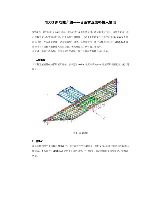
1工程概况本工程为某机场航站楼钢屋架部分。
总跨度为408m,屋架高度为8m,屋架采用钢管桁架结构(见图1)。
图1屋架结构2目录树该工程结构模型单元数为19196个。
由于该模型单元数量多,结构复杂,采用传统的结构编辑工作量大,不易维护。
3D3S10.1提供了目录树功能,可以使整体信息的编辑更直观便捷,如图2所示。
图2目录树右击任一属性选项,即可弹出编辑选择框,如图3所示。
图3“模型属性”对话框在编辑选择中,用户可以进行“定义”、“选择”、“显示”、“隐藏”和“属性”等操作。
通过目录树功能,可以对同一属性的单元进行批量修改和定义。
如要修改单元的截面特性,选择截面属性,右击属性选项,选择属性选项,软件会弹出属性编辑对话框,如图4所示。
图4“单元截面属性”对话框用户只要对属性值进行重新修改,就可以将原截面属性的所有单元定义成新的截面属性。
对于其他的属性,也可以用采用同样的操作方式进行编辑。
3表格输入输出对于结构复杂的模型来说,数据的显示和编辑显得尤为重要。
好的编辑操作能极大地提高软件的使用效率。
为此,3D3S10.1版本中特增加了表格的输入和输出功能。
点击菜单“显示查询”,选择“节点信息查询修改”,选择要查询的节点后,弹出对话框如图5所示。
图5“节点查询”对话框表格中会显示出所选择的节点信息。
包括节点坐标、节点荷载以及导荷载的信息。
用户可以在表格中直接编辑相关数值就可以完成节点信息的编辑。
3D3S快速安装说明书

3D3S快速安装说明
Insatll Instructions
目录
单机版 安装步骤 ------------------------------------------------ 4
步骤一 请正确安装AutoCad2004
------------------------ 4
步骤二 请安装3D3S软件 ---------------------------------------- 4
此时请点击确定将低版本卸载,卸载完成后再次双击3D3S安装盘.exe 进行安装即可。
Page 07
步骤三 启动3D3S软件,查看单位和软件模块信息。 双击3D3S快捷图标,启动后,在模块切换/帮助 菜单下 点击关于3D3S 命令:
从对话框中可以看到 用户名称和软件授权号,以及软件含有的功能模块信息。
2、当在服务运行的情况下拔除了网络锁,则重新插上网络锁后必须重新 启动服务。
Page 15
二、客户端安装步骤 网络版客户端的安装步骤请参照单机版的安装步骤执行。
Page 16
3D3S快速安装说明
Insatll Instructions
客户端安装步骤完成后需要设置IP地址。在模块切换/帮助菜单,找到网络/单 机版切换命令:
图2 网络锁服务管理程序界面 注意:关于参数ModuleID0到ModuleID2的数字,不需要用户进行干预。其具 体的含义说明,请参看光盘中详细说明文档后半部分的常见问题解决方法。
Page 14
图3 网络锁服务的启动与停止
注意: 1、如果服务管理工具与服务不在同一台机器运行,则无法通过服务管理 工具进行启动/停止服务的操作。
Page 03
单机版 安装步骤
- 1、下载文档前请自行甄别文档内容的完整性,平台不提供额外的编辑、内容补充、找答案等附加服务。
- 2、"仅部分预览"的文档,不可在线预览部分如存在完整性等问题,可反馈申请退款(可完整预览的文档不适用该条件!)。
- 3、如文档侵犯您的权益,请联系客服反馈,我们会尽快为您处理(人工客服工作时间:9:00-18:30)。
3D3SV11.0版软件功能介绍
任意空间结构设计模块 1. 3D3S 软件AutoCAD 平台由AutoCAD2004~2006升级为AutoCAD2007~ 2009; 2. 内置规范完全升级为新规范,包括抗震规范(GB50011-2010)、网格规范(JGJ7-2010)、混凝土结构设计规范(GB50010-2010)、高层建筑混凝土结构技术规程(JGJ3-2010);
3. 增加铝合金结构设计规范(GB50429-2007)进行构件验算的功能;
4. 增加完善了模型数据接口功能,支持的格式包括IFC 格式、SAP2000、ETABS 、MIDAS 、ANSYS 、ABAQUS 、STAAD ;
5. 新增按照截面插入点设置杆件偏心的功能;
通过调整截面插入点来对梁上表面进行对齐操作
数据转换所支持的格式
8.新增构件1轴方位调整的功能,可用于对不等肢角钢等非对称截面方位进行
调整;
6.新增将模型内力图、位移图
等3D3S实时显示效果保存
为dwg文件的功能;
7.增加将结构内力、位移、反
力和振型输出为excel表格
的功能;
得到Excel表格
9.验算结果查询对话框对于验算结果信息的显示更为详尽,包括验算过程中的塑性开展系数、稳定参数等;
10.新增可允许产生部分位移的支座设置功能;
通过输入支座的允许位移值来控制支座的滑移量,当位移值小于允许位移时则支座不产生反力。
11.新增节点局部坐标,可以轻松处理斜方向支座的问题;
节点局部坐标设置对话框
通过调整节点局部坐标来实现对于结构径向及切向的约束:
12.新增在任意结构中布置悬挂吊车的功能;
任意悬挂吊车设置对话框
通过选择节点可为在任意结构中布置悬挂吊车:
14.新增模型中显示构件计算长度的功能;
在验算结果显示中勾选显示
数值来显示计算长度:
13.新增构件按照优选分组进行显示的功能;
通过选择优选分组所在的层来显示同组构件:
15.新增按导荷载作用
范围对构件显示调整功能;
对于已经设置了导荷载的杆件可以直接进行复制、显示等操作,同时还可以对荷载所作用的范围进行复制来的到新的作用范围相同的荷载:
仅显示作用杆件
16.新增在部分杆件或节点上显示荷载的功能;
17.改进了彩色云图图标色条的背景颜色,保证与CAD的背景颜色一致,
便于输出方便打印的图像;
调整后的位移及内力云图标色条的背景颜色将自动保持与CAD背景颜色一致。
21.新增构件与直线相交打断的命令;
18.信息树性能得到大
幅提升,操作更为快速;
19.增加高级求解器提
升结构计算速度;
使用高级求解器后能够大幅提高结构的内力分析速度
20.新增模型分析日志
输出功能;
方便查看内力分析日志
22.新增对地震反应谱
进行人工调整的功能;
23.新增快捷命令菜单
使软件操作更为高效;
通过点击命令栏快捷键快捷的对模型进行操作。
24.新增手工添加封闭面的功能,使封闭面的生成更为便捷;
当封闭面无法正常生成时,可以手动添加需要的封闭面来进行导荷载。
自动生成导荷载封闭面
手工添加导荷载封闭面
25.调整优选分组功能,使对于杆件优选分组的操作更为便捷;
对不同的优选分组进行定义,并对每一组的截面优选范围进行选择,之后进行杆件截面优选。
26.新增验算结果表格输出功能,使对于设计结果的处理更为便捷;
软件中可将构件的验算结果输出为表格,更为方便查看和使用excel对表格进行编辑。
27.增加模型修改日志记录功能,使的对于模型修改功能的计录操作更为
便捷;
添加模型修改日志后,打开模型即可查看模型修改日志及模型相关信息。
28.调整了荷载组合设置界面,组合修改更加便捷;
选中组合后可直接在对话框右侧对组合参数进行修改。
29.增加连接单元属性定义功能;
可添加线性或非线性弹簧。
30.增加任意空间结构模型图纸生成功能;
通过使用施工图绘制功能,可直接有计算模型生成需要的杆件截面编号图及各种视图下的图纸。
31.调整构件查找界面,可直接缩放到需要查找的构件;
除了可着重显示构件、节点外,也可以直接缩放到该构件、节点。
多高层建筑结构设计模块
1.增加标准层、模型层快捷切换功能;
第一标准层第二标准层
第三标准层第四标准层
2.增加钢管刚接柱脚并对柱脚节点加劲肋倒角进行修正;
圆管刚接柱脚
3D3SV10 3D3SV11
钢管桁架结构设计模块
1.调整相贯节点验算功能,使节点验算更为便捷;
选中节点后可查看节点位置,对于不满足验算结果的节点可查看原因并对节点杆件进行调整。
构件属性的调整 端头切割的定义
端头约束调整
杆件内力调整 杆件截面调整
2. 增加部分用于后处理模型调整的功能;
当需要在焊接球设计时考虑周围圆管的相贯连接时,可先手动对节点进行焊接球设计,之后软件会自动将与之相连的圆管进行相贯处理。
3. 提高焊接球设计灵活性,支持对于包含有部分相贯杆件的焊接球设计;
网架与网壳结构设计模块
1.新增不同支座刚度模型杆件包络功能,保证设计安全;
对于同一个结构模型,如果无法判断实际的约束情况,保守起见,可以使用模型包络功能对不同约束的两个模型杆件截面进行包络,包络后
的模型各杆件截面取两个模型的较大者。
铰接支座模型弹性支座模型
包络模型
3.新增杆件夹角查询功能及模型最小夹角查询功能;
杆件夹角查询功能用以确定两根杆件之间的夹角是否能够满足相关规范要求及节点构造要求,模型最小夹角查询功能用以查寻整个模型中的最小杆件夹角值。
杆件夹角查询模型最小夹角查询
2.螺栓球设计中的参数设置更为详细;
3D3SV10 3D3SV11
4. 新增螺栓球加辅助孔功能;
根据需要我们可以在螺栓球上增加辅助孔。
加辅助孔
5. 新增在螺栓球设计过程中选择想要使用的螺栓球型号进行设计的功能;
通过选择需要用于设计的螺栓球来对节点进行设计而不需要在螺栓球库中对螺栓球进行删除。
三孔 四孔
6.增加螺栓和套筒强度咨询功能;
变电塔架结构设计模块
1.变电塔架荷载快捷添加功能;
通过选择节点布置导线及地线荷载
2.格构式变电塔架节点设计功能;
3.格构式电力塔架图纸绘制;
塔段详图
节点详图
4.人字柱变电塔架节点设计功能;
5.人字柱变电塔架梁柱施工图绘制;
梁详图
柱详图
6.变电塔架设计过程中可任意添加板件及其他配件;
软件提供了直接添加板件的功能,可在模型中添加任意板件或挂线环等构件,并可将节点保存下来下次设计时使用。
挂线环封口板
非线性分析系统
1.改善了缺陷添加功能,可根据不同工况&组合作用下的线性屈曲模态添
加结构初始缺陷;
首先进行线性稳定分析,之后在进行非线性分析时添选
择工况及对应的屈曲模态,即可将对应模态作为缺陷加到结
构中。
2.增加根据构件原长、初应变、温度添加构件预应力的方式,使预应力
添加更为灵活;。