万高双电源WATSG说明书
万高双电源用户手册介绍
4.4.1 A 型控制器 ............................................................. 10 4.4.2 B 型控制器 ............................................................. 11 4.5 使用方法 ....................................................................... 14 5 维护与故障排除................................................................. 15 5.1 维护................................................................................ 15 5.2 常见故障及排除 ........................................................... 15 5.3 售后服务 ....................................................................... 16 附录: WATSN 系列产品用户接线图 ................................ 18
高功率变压器电源功耗测试仪操作手册说明书
FREE Download App HTANALYSIS ™ for iOS & Android devicesavailable on the available on theModules Database,More than 30,000.Troubleshooting Assistant.Manage the modules in your instrumenttrough your mobile device.Add new , Delete or check what is insideyour I-V Curve Tracer.The only App that helps you with online FAQ.Depending on the outline of the I-V Curve you havemeasured, the app will suggest you the possiblecauses of the problem that you have faced.Download the FREE App HTANALYSIS ™ to use HTCloud ™database and share measures with your colleaguesanytime and from any place on the planet .Upload your measures onto HTCloud ™ to find them on your PC software TOPVIEW real-time.HT Cloud ™Share. Whenever,whatever and wherever.I-V Curve and much more.Expected degradation.What is the truth? Jump Function ™Data Analysis. OK or NOT OK?With your mobile device, HTANALYSIS ™helps you to understand the problemsyou may have in the PV Installations.Enter the installation date of the PV systemand the app will tell you the truthabout the real performance drop.Select your I-V Curve and analyze it.You can add a photo , an audio note ,a text note and a video .Yes, all can be completed on the field .HTANALYSIS.I-V Curve and much more.1500V MULTISTRINGIrradiance sensor HT304N.Solar02 remote unit.Only one person needed to measure.› I -V Curve measurement up to 1500V and 15A*› Power measurement of modules and strings › Open-circuit voltage (Voc) up to 1500V › Short-circuit current (Isc) up to 15A ›I rradiance measurement with HT304N remote sensor › Ambient and Panel temperature with PT300N probe**›W ireless environmental measurements with Solar 02 remote unit **› N o distance limits for environmental measurements with Solar 02 remote unit I-V Curve Measurement* 1000V/15A or 1500V/10A ** Check standard and optional accessories › 1500V & 15A: Suitable also for new PV plants with 1500VDC string voltage.›C ompact, lightweight and On-board screen: I-V500w needs only one person thanks to the on-board screen and returns immediate test results with OK or NOT OK outcome.› Multi-String Autosequence ™: Just few seconds to measure, save data and move to next string.› Wi-Fi Connection: Connect your smartphone or tablet to download and analyze in details your measures with exclusive features like Troubleshooting Assistant, Jump function and others available only on the APP HTANALYSIS ™.Why I-V500w?All that you need is KITKELVIN Test Leads Accessory.Multi-String Auto Sequence ™Dramatically decrease your PV String testing time with the NEW KITKELVIN.KITKELVIN provides an Auto Sequence function to HT Curve Tracersto reduce testing time up to 75%! KITKELVIN provides 2 leads for a singleoperator to move from string to string in a combiner box for fast testing. TheAuto-sequence is Start, Acquire, Manual store, Rearm. The Start command isautomatically initiated when the operator connects the probes across a stringor panel, with Voc triggering the next acquisition sequence.Memory and Module Database No need for external storage . The Internal Memory can store up to 249 I-V Curves (128 test points) and up to 999 Quick Checks of Voc & Isc . The intuitive User Interface (UI) provides easy access to all of your stored data including I-V Curves, power curves and numerical values in the table while in use. To ease measurement set up, HT Solar instruments store up to 30 modules to ensure you have all panels in the field being tested . Whenyou get to the field, you are ready to go for the entire day!Measurement Results (OPC & STC)The acquired I-V data or the operating conditions (OPC) is the true data acquired during I-V curve test . Taking the panel characteristics, the environmental measures (Irradiance & Temp) the instrument transforms these data points (OPC) to create the equivalent STC (Standard Test Condition) curve to evaluate if the panel or string is operating to specification .Report creation with TopView ™ SoftwareMeasuring Solar Field is often only the beginning of your project.Customers want to see proof their fields are working as promised.HT’s Copyrighted Software, TopView makes the business ofreport generation a breeze . Easy download, customized naming ofdata fields, File storing and sharing trough HT Cloud ™, analyzingcapabilities and display options to your preference . You cancompare Strings, Combiner boxes even Farms year over year to makedescribing the state of the field intuitive and obvious. I n addition,TopView incorporates standard templates for professional-lookingreports customizable with your logo and company information.CROSS TABLE FUNCTIONSM A D E I T A L Y I N b s h _I V 500w _e n 1-00Electrical specifications General specifications VDC Voltage @ OPCRange (V) (*): 15.0 ÷ 1499.9Resolution (V): 0.1÷ 0.3Accuracy: ±(0.5%rdg+2dgt)(*) The I-V curve and Rs measurements start for VDC > 15V and the accuracy is defined for VDC > 20V IDC Current @ OPCRange (A): 0.10 ÷ 15.00Resolution (A): 0.01Accuracy: ±(1.0%rdg+2dgt)Max Power @ OPC (Vmpp >30V, Impp >2A)Range (W) (*): 50 ÷ 99999Resolution (W): 1Accuracy: ±(1.0%rdg+6dgt)Vmpp = Maximum power voltage, Impp = Maximum Power Current(*) Max measurable value of Power must include FF value (~ 0.7) > Pmax = 1000V x 15A x 0.7 = 10500W Pmax = 1500V x 10A x 0.7 = 10500WVDC Voltage (@ STC ), I-V, IVCKRange (V): 5.0 ÷ 999.9Resolution (V): 0.1Accuracy (*,**): ±(4.0%rdg+2dgt)IDC Current (@ STC), I-V, IVCKRange (A): 0.10 ÷ 99.00Resolution (A): 0.01Accuracy (**): ±(4.0%rdg+2dgt)Max Power @ STC (Vmpp >30V, Impp >2A)Range (W) (*, **): 50 ÷ 99999Resolution (W): 1Global accuracy (**): ±(5.0%rdg+1dgt)Vmpp = Maximum power voltage, Impp = Maximum Power Current(*) Measurements start for VDC > 15V and the accuracy is defined for VDC > 20V (**) Test conditions:• Test cond.: Steady Irrad.≥700W/m 2, spectrum AM 1.5,solar incidence vs perpendicular. ≤ ± 25°, Cells Temp. [15..65°C] • Global accuracy include contribute of solar sensor and its measuring circuit Irradiance (with reference cell)Range (mV): 1.0 ÷ 100.0Resolution (mV): 0.1Accuracy: ±(1.0%rdg+5dgt)Temperature of module (with auxiliary PT1000 probe)Range (°C): -20.0 ÷ 100.0Resolution (°C): 0.1Accuracy: ±(1.0%rdg+1°C)Display and memory Features: 128x128pxl custom LCD with backlight Memory capacity: 256kbytes Saved data: 249 curves (I-V curve test), 999 IVCK Power supply I-V500w internal power supply: 6x1.5V alkaline batteries type LR6, AA, AM3, MN 1500Autonomy of I-V500w: > 249 curve (I-V curve test), 999 IVCK test SOLAR-02 power supply: 4x1.5V alkaline batteries type AAA LR03SOLAR-02 max recording time (@ IP=5s): approx 1.5h Output interface PC communication port: optical/USB and WiFi Interface with SOLAR-02: wireless RF comunication (max distance 1m)Mechanical features Dimensions (L x W x H): 235x165x75mm Weight (batteries included): 1.2kg Environmental conditions:Reference temperature: 23°C ± 5°C Working temperature: 0° ÷ 40°C Working humidity: <80%HR Storage temperature (batt. not included): -10 ÷ 60°C Storage humidity: <80%HR General reference standards:Safety: IEC/EN61010-1EMC: IEC/EN61326-1Safety of measurement accessories: IEC/EN61010-031I-V curve measurement: IEC/EN60891 (I-V curve test) IEC/EN60904-5 (Temperature measurement)Insulation: double insulation Pollution degree: 2Overvoltage category: CAT II 1000V DC, CAT III 300V AC to ground Max 1500V among inputs P1, P2, C1, c2Max altitude of use: 2000m Accessories provided • KITGSC4 Set of 4 cables banana 4mm, 2m + 4 alligator clips • KITPVMC3 Set of 2 adapters with connector compliance MC3 • KITPVMC4 Set of 2 adapters with connector compliance MC4 • HT304N Reference cell for irradiance measurement with set of fixed screws • M304 Mechanical inclinometer for detection of sun incidence angle • VA500 Hard carrying case• SP-5100 Hands-free kit• TOPVIEW2006 P C Windows software + optical/USB connection cable • User’s manual on CD-ROM• Quick start guide• Calibration certificate ISO9000 for I-V500w•C alibration certificate ISO9000 for HT304NOptional Accessories •S OL AR-02 Remote unit •P T300N PT1000 probe for cell temperature measurement •K ITPVEXT25M Set of 2 cables banana 4mm, Green/Black, 25m •M PP300Accessory to check on PV plants with multi MPPT up to 3•K ITKEL VIN Autosequence ™ test leads kit HT ITALIA S.R.L.Via della Boaria, 4048018 Faenza (RA) Italia T +39 0546 621002F +39 0546 621144E-mail *******************ht-instruments.it HT INSTRUMENTS SL C/ Legalitat, 89 08024 Barcelona, España Tel. +34 93 4081777 Fax +34 93 4083630 E-mail:*********************ht-instruments.es HT INSTRUMENTS GMBH Am Waldfriedhof, 1b D-41352 Korschenbroich, Deutschland Tel. + 49 (0)2161 564 581 Fax + 49 (0)2161 564 583 E-mail: **********************ht-instruments.de HT INSTRUMENTS AMERICAS LLC 2804 Patricia Lane Billings, MT 59102USATel. 171****9323E-mail: **************************。
万高双电源用户手册介绍

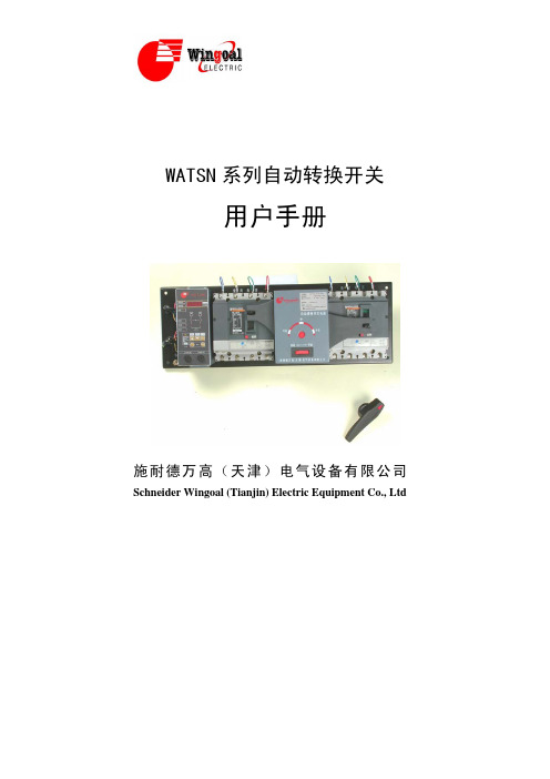
WATSN 系列不同型号产品外形见图 1~4,安装尺寸见表 3
护。未按使用手册操作而造成的不良后果,施耐德电气公司将不负任 何责任。
目录
1 概述........................................................................................ 1 1.1 产品简介 ......................................................................... 1 1.2 产品主要特点 ................................................................. 1 1.3 产品型号说明............................................................... 2
表 1 WATSN 自动转换开关控制器功能一览
控制器 工作电压① 工作频率 3 个工作位置 常用电源闭合 备用电源闭合 常用和备用电源均断开 (0 位) 3 种操作方式 自动操作 手动遥控 手柄操作② 自动操作
A(内置式) AC220 50/60Hz
■ ■ ■
■
■ቤተ መጻሕፍቲ ባይዱ
监控常用电源和自动切 ■(三相断相、失压
标准产品
WATSN
PC
非标准产品
X: 带消防联动功能
工作 方式
R: 自投自复 S: 自投不自复 I: 互为备用
PC级自动转换开关,不带短 路、过载保护
开关级数:3极、4极
电流等级:32A/40A/63A/80A/100A
控制器类型:A型、B型、D型 施耐德万高(天津)电气设备 有限公司自动转换开关电器
万高-WATSN-样本提案3[1].24
![万高-WATSN-样本提案3[1].24](https://img.taocdn.com/s3/m/4f63a024482fb4daa58d4b45.png)
短路容量与ATSE........................................................................... 29 系统配合与ATSE........................................................................... 30 完全选择性与ATSE .......................................................................31 电动机负荷与ATSE .......................................................................32 配电盘与ATSE ..............................................................................33
情况下保证可靠的接通回路。
电流800A至1600A WATSN800-1600
目录
标准与选型 .................................................................... 1
功能特性.....................................................................3-9
WATSN系列自动转换开关若选择具有过电流脱扣器的断路器作为执行器 则属于CB级自动转换开关。具备选择性的保护功能,能对下端的负荷和电 缆提供短路和过载保护;其接通和分断能力远大于使用接触器和继电器等
WATSN用户手册-中文版-07.11.15
返回延时
中性线误接相线保护功 能 转换信号发出后,超时 故障切断功能
■标准配置
■
■
■ ■
0 秒 、5 秒 、 15 秒、 30 秒 精度 ≤5℅ 0 秒 、5 秒 、15 秒 、 30 秒 精度 ≤5℅ ■
■ □ 可选功能
■ ■ ■
■
■ ■ ■ ■
0-255 秒连续可调
0-255 秒连续可调
下面的符号将用于本手册的说明,提醒您注意潜在的 危险,或者请您注意那些阐述、简化过程和关键操作。
! :安全警示标志,提示您如果违规操作可能造成
人身安全危险或本开关的不可恢复性损坏。
;: 关键性操作,提示您使用不当时,可能使控制
器工作于非正常状态。
":提供另外的信息或简化的操作方法。
请注意: 电气设备应该让有资格的专业人员进行安装、操作、使用、维
护。未按使用手册操作而造成的不良后果,施耐德电气公司将不负任 何责任。
目录
1 概述........................................................................................ 1 1.1 产品简介 ......................................................................... 1 1.2 产品主要特点 ................................................................. 1 1.3 产品型号说明............................................................... 2
施耐德万高双电源自动转换开关
施耐德万高双电源自动转换开关施耐德万高双电源自动转换开关WATSN 系列自动转换开关是施耐德万高公司生产销售的利用微机控制技术开发研制的新一代自动转换开关。
该开关以施耐德电气公司的 Multi9 系列、Compact 系列断路器或符合开关为执行元件,并配以机电一体化、带机电双重联锁的新型控制机构,特别适合用在不容许电源断电的重要供电场所即重要负荷。
为满足现场需求,自动转换开关可实现自投自复、自投不自复、互为备用三种不同的工作方式。
实现市电对市电双电源 WATSN-40 负荷隔离开关INT WATSN-63/63 3CBRX WATSNA 2P 40A WATSNA 40A/2 WATSNA 63/16 3CBR-D WATSNA 63/40-4CBR WATSNA 63/63 2CBR-C WATSNA 63/63 4CBR-D WATSNA-1004PCR WATSNA-100 4PCR INT WATSNA-100/ 4PCR WATSNA-100/100 3CBS WATSNA-100/100 3PCR WATSNA-100/100 4CBI WATSNA-100/100 4CBR WATSNA-100/100 4CBS WATSNA-100/100 4PCR WATSNA-100/100.3CBR WATSNA-100/100.4CBR WATSNA-100/100.4PCR WATSNA-100/100A 3CBR WATSNA-100/100A 4CBIF WATSN-63/63 3CBR WATSNA-100/100A 4CBR WATSNA-100/100A 4CBRXF WATSNA-100/100A 4PCR WATSNA-100/16 .3CBR WATSNA-100/25 3CBR WATSNA-100/25A 4CBR WATSNA-100/32 .3CBR WATSNA-100/32 3CBR WATSNA-100/32.4CBR WATSNA-100/40 .3CBR WATSNA-100/40 3CBR WATSNA-100/40 4CBR WATSNA-100/40 4P PCRWATSNA-100/503CBRWATSNA-100/50.4CBRWATSNA-100/50A 4CBRWATSNA-100/63 3CBRWATSNA-100/63 4CBRWATSNA-100/63 4PPCRWATSNA-100/63.3CBRWATSNA-100/63A 4CBRWATSNA-100/63A 4CBTRWATSNA-100/63A 4PCRWATSNA-100/80 4CBRWATSNA-100/80 4CBR XFWATSNA-100/80 4PCRWATSNA-100/80.3CBRWATSNA-100/80.3CBSWATSNA-100/80.4CBRWATSNA-100/80A 3CBRWATSNA-100/80A4CBRWATSNA-100/80A.3CBR-XWATSNA-100-100-3CBIWATSNA-100-100-4PCRWATSNA-100-40-3CBRSTR22SEWATSNA-100A4PCRWATSNA-125/3RWATSNA-125A/4PCRWATSNA-16/162CBRWATSNA-160.4CBRWATSNA-160/1004PCRWATSNA-160/100.4CBRWATSNA-160/100A 4CBRWATSNA-160/100A4PCRWATSNA-160/125 4CBRWATSNA-160/125.3CBRWATSNA-160/125A 4CBRWATSNA-160/125A 4PCRWATSNA-160/160 3CBIWATSNA-160/160 3CBRWATSNA-160/160 4CBRWATSNA-160/160.3CBRWATSNA-160/160.3CBSWATSNA-160/160.3CBS手柄WATSNA-160/160.3PCIF WATSNA-160/160.4CBR WATSNA-160/160.4PCR WATSNA-160/160-4CBR WATSNA-160/160A 3PCR WATSNA-160/160A 4CBR WATSNA-160/160A 4CBRXF WATSNA-160/160A 4PCR WATSNA-160-125-3CBI WATSNA-160-40-3CBI WATSNA-160A/120A 3CBR WATSNA-160N/125-3CBR WATSNA-200A/4PCR WATSNA-250/125 4CBR WATSNA-250/160 4PCR WATSNA-250/200 4PCR WATSNA-250/200.3CBR WATSNA-250/200.4CBR WATSNA-250/200.4CBS WATSNA-250/200A 4CBR WATSNA-250/250 3CBS WATSNA-250/250 4BCR WATSNA-250/250 4PCR WATSNA-250/250.4CBR WATSNA-250/250A 4CBR WATSNA-250/250A.3CBR WATSNA-250/H200A 3CBR WATSNA-250/H250A 3CBR双电源是指:一种由微处理器控制,用于电网系统中网电与网电或网电与发电机电源启动切换的装置,可使电源连续源供电。
施耐德万高 产品2014.12.18

n多种系统连接方式
Ø 两层(100-300点) Ø 三层(300点以上) Ø 混合(500-1000点)
Wingoal Marketing
WEFPT
WEFPS
……
WEFPJ
……
WEFPT
15
选型与配置
WATSG系列自动转换开关
PC级自动转换开关
选型指南
WATSG B 100
4 RF
A
B
C
D
E
F
6 1.05
0.5
0.05
交
流
AC-33A AC-33B
10
1.05
0.45 ≤100A 0.35 >100A h
0.05
AC-35A AC-35B
3.0 1.05
0.50
0.05
AC-36A AC-36B
1.5 1.05
d
0.05
注:GB14048.11-2002标准中AC33的试验电流为6倍等同于现在的AC33iA
拨码开关 ■ 一体式 ■
■ ■
LCD ■ 分体式 ■ ■
WATSG系列
施耐德电气 – 部门 – 姓名 – 日期
23
附件
● X—消防联动功能
● 发生火灾时,由消防控制中心发出信号切断非消防负荷 ● 信号类型:DC24V恒压/脉冲,AC220V恒压/脉冲 ● 适用于B型/C型控制器选配
● F—反馈信号功能
施耐德电气 – 部门 – 姓名 – 日期
12
WEFP电气火灾监控系统
● 通过检测回路泄漏电流和 温度非正常升高(组合式 可监测过电流)造成潜在 的火灾隐患,防患于未然
WEFPS
● 系统构成灵活,方案多样
WATSN常见问题

常见问题CB级产品和PC级产品有何区别?PC级:能够接通、承载但不用于分断短路电流的ATSECB级:配备过电流脱扣器的ATS,它的主触头能够接通并用于分断短路电流CB 级产品及PC级产品孰优孰劣?不能泛泛而谈,需根据不同的现场需求,不同厂家产品的制造技术、工艺、品质管理而定。
选择性是配电系统的基本要求,对CB级产品而言,可以根据生产厂家提供的数据进行选型,实现选择性;对PC级产品而言,就需要在ATSE的进线端加装短路电流保护器:熔断器或断路器,来实现选择性的要求。
CB级产品自身带有电流故障保护有利于降低成本及系统复杂度。
对于消防泵类负载,发生火警时,设备的安全和供电的连续性相比已不再是首要考虑的因素,此时PC级产品比较适合。
但对照明类负荷或生产过程电动机负载,CB级产品的保护特性将保证供电连续性及负载安全,如果选用PC级产品,则必须在进线端加过电流保护电器,加大箱体的尺寸和造价,同时易出现故障状态下的重合闸,扩大事故的影响范围。
所以CB级产品和PC级产品的选择,视具体应用而定。
WATSN系列产品标准配置的断路器具体为什么形式?•63A 以下产品配C65N C型曲线断路器•100A~250A 产品配Compact NS100~250 N 断路器 TMD电磁脱扣器•400A~630A 产品配Compact NS100~250 N 断路器 STR23SE电子脱扣器如客户对断路器的分断能力或脱扣器的形式有其它选择,请再产品订购时加以说明。
63A 以下产品属性类型分断能力 (KA)脱扣曲线 瞬时脱扣特性C (5~10) lnC65N 6D (10~14) lnC (5~10) lnC65H 10D (10~14) lnC (7~10) lnC65L 15D (10~14) ln* 由于鼠笼式电机启动电流为6~9倍,20ms时出现的尖峰电流又是启动电流的2倍,而C65系列D曲线的断路器的短路保护的动作值也是20ms,动作倍数是10 ~14倍,为了保证可靠工作,我们建议选择断路器时应使断路器能够有效地躲过电动机的尖峰电流,因此我们建议放大一档选择D曲线的断路器。
wellstar电源部分说明书
第四章供电系统一、概述WELL STAR综合录井仪供电系统有接地保护、防爆接线盒、安全控制系统、变压器、配电系统等部分。
仪器能适应多种井场发电机,电源输入电压440V(线电压,以下若无特殊说明,三相电均指线电压)、380V、220V;频率50/60Hz均可。
本系统在设计中充分考虑到用户操作和检修方便。
为了使工作人员接电源线时不用每次都拆装电缆通道(MCT),在仪器房储藏室设置了一个总电源防爆接线盒,电源线每次只要接到这个接线盒就可以了,而从接线盒通过电缆通道接到仪器房内安全控制系统的电缆则在仪器出厂前就一次性安装好了。
电源在输入到用电设备之前,都要经过电源配电箱统一控制。
各部分电气设备都有自己单独的断路器。
在操作和维修时可以互不干扰。
断路器不仅可以控制电源的通断,也是短路、过载等电路故障的保护器。
二、接地保护供电系统拥有可靠的接地保护。
电气设备发生漏电现象时,电流会通过接地线迅速流入大地,使外壳仍保持零电位;这时,系统的保护装置(如断路器等)就能及时切断电源。
仪器房电源通过隔离变压器实现输入输出隔离,地线也隔离。
所以在本系统中,有两路接地输入,一是通过仪器房外壳上的接地柱与仪器所配的接地棒连接,接地棒埋入大地,从而达到仪器房箱体接地;二是电源输入线中的地线与井场发电机接地相连,然后通过防爆接线盒再经过安全控制系统输到变压器输入端。
需要注意的是,在安全控制系统中,地线是与电源都受安全控制系统控制而同时通断的,这是防爆的要求。
在仪器房内部,凡固定安装在仪器房箱体上的设备如烘箱、空调等都可以通过其金属外壳直接与仪器房相连接。
配电箱本身也安装在仪器房箱体上,在配电箱最下面的一根导轨上安装了一排接线端子,其中有14个黄绿色的接地线端子,它们通过导轨相互导通,并且与配电箱外壳连接,进而使这些接地端子都达到接地目的。
从这些端子分别引出若干导线与各电源插座的接地线相连,所有的用电设备(包括上面提到过的安装在仪器房箱体上的设备)都可以通过电源插座中的这根接地线来实现接地保护。
万高双电源用户手册

95% • 污染等级为Ⅲ级
2.2 电气性能及功能
WATSN 自动转换开关根据工作电源的电压状态,以及用户所设 置的工作方式,决定是否从一个电源转向另一个电源。它的功能取决 于其所配的控制器,控制器包括 A 型和 B 型两种,其具备的主要功能 如表 1 所示。
1 概述
1.1 产品简介
WATSN 系列自动转换开关是我公司利用微机控制技术开发研制的 新一代自动转换开关。该开关以施耐德电气公司的 Multi9 系列、 Compact 系列断路器或负荷开关为执行元件,并配以机电一体化、带 机电双重联锁的新型控制机构,特别适合用在不容许电源断电的重要 供电场所。为满足现场需求,自动转换开关可实现自投自复、自投不 自复、互为备用三种不同的工作方式。
表 1 WATSN 自动转换开关控制器功能一览
控制器 工作电压① 工作频率 3 个工作位置 常用电源闭合 备用电源闭合 常用和备用电源均断开 (0 位) 3 种操作方式 自动操作 手动遥控 手柄操作② 自动操作
A(内置式) AC220 50/60Hz
■ ■ ■
■
■
监控常用电源和自动切 ■(三相断相、失压
3 开箱检查注意事项................................................................ 6 4 安装使用.............................................................................. 7
2 常规特性及功能.................................................................... 3 2.1 常规特性.......................................................................... 3 2.2 电气性能及功能.............................................................. 4
施耐德万高D型控制器使用说明-

0x0005 遥控投备
0x0009 遥控双分
3,6
WTS-D800~5000系列没有遥控双分
59
3B
1
常用欠压阀值
3,6
V
60
3C
1
常用过压阀值
3,6
V
61
3D
1
备用欠压阀值
3,6
V
62
3E
1
备用过压阀值
3,6
V
63
3F
1
过流阀值
3,6
A
64
40
1
变比
3,6
--
备注:
计算机接收到该响应信息后表示该命令已发送到控制器。建议计算机以1秒的发送周期向控制器发命令信息,以利于控制器做相应处理。如果控制器因处理其他任务而未能立即向计算机回答响应信息,计算机可在下一个发送周期继续发送命令信息。
1
备用CA线电压
3
V
38
26
1
A相电流
3
A
39
27
1
B相电流
3
A
40
28
1
C相电流
3
A
41
29
1
功率
3
kW
42
2A
1
电能
3
kWh
43
2B
1
故障标志1
低字节
BIT7=1 --备用缺相
BIT6=1 --备用欠压
BIT5 --空
BIT4=1 --备用过压
BIT3=1 --常用缺相
BIT2=1 --过流
BIT1=1 --常用欠压
错误校验码(CRC码):主机或从机可用校验码进行判别接收信息是否出错。有时,由于电子噪声或其他一些干扰,信息在传输过程中会发生细微的变化,错误校验码保证了主机或从机对在传送过程中出错的信息不起作用。这样增加了系统的安全和效率。错误校验采用CRC-16校验方法,占两个字节,低字节在前。
施耐德万高技术支持

施耐德万高技术支持技术支持Q&A技术支持1.1 综述1. 双电源自动转换系统中CB级和PC级分别是什么意思?施耐德是哪一类的产品?在双电源转换系统中,PC级是指能够接通、承载、但不用于分断短路电流的双电源转换系统(无过电流保护);CB级是指配备过电流脱扣器双电源转换系统,它的主触头能够接通并用于分断短路电流(即具备短路过载保护功能)。
施耐德电源转换开关产品中既有CB级(WATSN、ATNSX、ATMT、WSATS)的产品,也有PC级(WOTPC、WBTPC、WTS、WATSG、WATSN、WSATS)产品。
2. 自动转换开关电器常用使用类别怎样选用?使用类别:ATSE(自动转换开关电器)常选用AC-33A、AC-33B、AC-33 iA、AC-33iB作为其使用类别。
AC-33 iA、AC-33iB含义是:系统总负荷包含笼型电动机及阻性负载。
AC-33A、AC-33B含义是:电动机负载或包含电动机、电阻负载和30%以下白炽灯负载的混合负载。
其中A表示频繁操作,B表示不频繁操作。
3. 建筑消防电气设计上有没有对电源切换的要求, 如果有应设置在什么位置?火灾自动报警、消防通信等消防用电设备均设有应急电源。
当使用的电源故障停电时,被停止供电的重要负荷采用电源自动切换装置(ATS)切换至另一电源。
《高层民用建筑设计防火规范》第9.1.2条规定:“高层建筑的消防控制室、消防水泵、消防电梯、防烟排烟风机等的供电,应在最末一级配电箱处设置自动切换装置。
4. 首端与末端设置转换开关的不同点?ATS设在首端 (如在变电所低压的第一级配电处)和设在末端相比,末端设ATS时,除了电源故障停电能自动切换外,当配电设备故障或低压线路上发生故障而停电时,末端ATS也能动作,增加了负荷的供电可靠性;首端设ATS时,如果配电设备或低压线路发生故障而停电,该ATS不动作,这样就无法保证负荷的继续供电,所以末端ATS比首端ATS更为可靠。
Eaton Ferrups FE 50Hz Tower Series 配置指南说明书
Eaton FerrupsFE 50Hz Tower SeriesFerrups CTO Worksheet (2)Ferrups 50Hz Tower Series Quick Reference Sheet (3)Ferrups CTO DetailsFE1.4kVA…………………………………………………………. 1.4k-1FE3.1kVA…………………………………………………………. 3.1k-1FE5.3kVA…………………………………………………………..5.3k-1Additional Ferrups External Options (21)Voltage Matching TransformersCaster KitsConnectivity OptionsSoftwarerating, voltages, runtime, and other options pertaining to the FERRUPS configuration. As you select theoptions needed, they will become part of the CTO number.Sample CTO Number: FS500OU1A0A0A0A.External battery packs, bypass switches and other external options should be ordered as separate items.UPS CTO Order Code List Price Discount Net Price Base Unit F_Input / Output VoltageBattery and Battery ChargerInternal Maintenance Bypass SwitchInput ConnectionOutput ConnectionInternal OptionsComplete UPS CTO Number F_UPS SubtotalBattery Pack Selected:Other External Battery Options Selected:External Maintenance Bypass Switch Selected:OptionsNote: Eaton offers a complete line of Power Distribution Units (PDUs). Please contact your sales representative or visit our websites, and , for details.Sub TotalFreightInsuranceTax/DutyQuote TotalA = NoneB 1 = AVR/ DVR (recommended for PFC loads)D = Anchor Kit for structural slab floorE = Anchor Kit for raised of access floor I 1 = AVR/DVR with Anchor kit for slabJ 1 = AVR/DVR with Anchor kit for access floor Q= Neutral to ground bond removal (shipboard) R 1 = Neutral to ground removed & AVR/DVR S = Neutral to ground removed & anchor kit 1. AVR not available on FS (1.4kVA) modelInternal Options (15)A = Hardwired O = IEC320 C14 S = IEC309 16AInput (6) FS = 1.4kVA FV = 3.1kVA FX = 5.3kVAModels FS, & FV have no front panel display. An optional RCK-0007 remote display can be ordered to provide display function through the RS232 port.See page 21.Base Unit (1-2)Note: Not all options are available on each base unit. Options restrictions exist. Please consult information in this guide for further detail.* Eaton has announced the End of Life of these Ferrups options. Products will be available while supplies last.0 = Standard Battery/ Standard Charger 1 = ERT Internal Battery/ Standard Charger 3 = Setup for Internal w/o Battery/ Std Charger 4 = External Battery/ Standard Charger 5 = External Battery/ 10A Charger 6 = External Battery/ 15A Charger 7 = External Battery/ 20A ChargerBattery / Battery Charger (4)Capacity: 1.4kVA/ 1.0kW Dimensions: 15.1” x 15.25” x 20.2" Input Voltage: 220, 230, 240V (HxWxD) 385mm x 390mm x 515mm Output Voltage: 220, 230, 240V Weight (with batteries1): 70kg / 154lbWeight (without batteries): 45.5kg / 100lbSee Eaton Ferrups FE Series 50Hz Product Focus (ILP0368) for additional product specification.1. Weights are approximate for standard batteries, option 0 for digit 4.Base Unit Digits 1-2 Base Model, Frequency, Cabinet Style CTO Order Code Base Price QFE1.4kVA, 50 Hz Tower FS $8,392Input / Output Voltage Digit 3 Input Voltage Output Voltage CTO Order Code Option Price 220 220 4 $0 230 230 5 $0 240 240 6 $0Battery and Battery Charger Digit 4 Battery Configuration Battery Charger CTO Order Code Option Price 14 minute internal (37m half load) standard 0 $319 21 minute internal (25m half load) standard 1 $490 Set up for internal (less batteries) standard 3 $97 set up for external battery pack1 standard 4 $50 1 Includes External Battery ConnectorOrder desired external battery pack as a separate line. See page 1.4k-3.Internal Maintenance Bypass Switch Digit 5 Internal Maintenance Bypass Switch CTO Order Code Option Price No internal maintenance bypass switch option available1 0 $0 1External maintenance bypass switch available for hardwired systems. Order desired maintenance bypass switch as a separate line item on your order. See page 1.4k-3.Input Voltage Selected Input ConnectionCTO Order Code Option PriceAnyHardwired 1A $45 220, 230, 240IEC320 – Jumper Cord 3O$01 Hardwired input requires hardwired output 2Cannot be used with 15 Amp battery charger 3Limits output connections to two panelsDesignated by 8 digits within the unit CTO number. These eight digits allow selection of the type and quantity for up to four different types of receptacles.•Three output slots available when a NEMA line cord is selected• Two output slots available when an international line cord is selected.• For multiple quantities of one receptacle type, enter the type once with the total quantity (ex: B2 not B1B1). • Always enter the receptacle types alphabetically (ex: B1C1 not C1B1).• If hardwire output is desired, select type “A”, quantity “0” for all four receptacle types (ex: A0A0A0A0). •If fewer than four types of receptacle are selected, complete the remaining receptacle digits with A0 (ex: B1C1A0A0).Output Voltage RequiredOutput ConnectionCTO Order Code Option Priceper Panel Type Qty AnyHardwired 1A 0 $0 220, 230, 240VIEC320 10A (Qty 2 per panel)U$50Receptacle Output Connection CTO Order Code_ _ _ _ _ _ A 0 Hardwire Output Connection CTO Order CodeA 0 A 0 A 0 A 01Hardwired output requires hardwired inputInternal OptionsDigit 15OptionCTO Order Code Option PriceNo other optionA $0 Anchor Kit for structural slab floor D $200 Anchor Kit for raised or access floorE $200 Neutral to Ground bond removal (For Shipboard Use)Q $25External battery packs, bypass switches and other external options are not a part of the CTO number and will need to be ordered as separate line items. Some external options require that the UPS be configured for use with the option. More options are listed in the Additional External Options section of this g uide.Output ConnectionDigits 7-14Runtime Full/Half Battery Charger Required Order Number List Price 38m/1h38m Standard Battery Charger 2me $2,211 55m/2h26m Standard Battery Charger 3me $2,557 Option Order Number List Price External Battery Connector Extension (72”)Also recommended for third-party external battery configurations.BCS-0108 $1421UPS Input Voltage Switch Type Order Number List Price220, 230, 240 MBB (Make Before Break) BPE01MBB1A $704 MBB, with AS/400 (iSeries) Option BPE01MBBAS1A $7331 Bypass Switch must be mounted on the wall near the UPS.Capacity: 3.1kVA/ 2.2kW Dimensions: 21.2” x 15.25” x 22.9" Input Voltage: 220, 230, 240V (HxWxD) 540mm x 390mm x 585mm Output Voltage: 220, 230, 240V Weight (with batteries1): 116kg / 256lbWeight (without batteries): 69kg / 152lbSee Eaton Ferrups FE Series 50Hz Product Focus (ILP0368) for additional product specification.1. Weights are approximate for standard batteries, option 0 for digit 4.Base Unit Digits 1-2 Base Model, Frequency, Cabinet Style CTO Order Code Base Price QFE3.1kVA, 50 Hz Tower FV $12,765Input / Output Voltage Digit 3 Input Voltage Output Voltage CTO Order Code Option Price 220 220 4 $0 230 230 5 $0 240 240 6 $0Battery and Battery Charger Digit 4 Battery Configuration Battery Charger CTO Order Code Option Price 14 minute internal (35m half load) standard 0 $833 37 minute internal (1h38m half load) standard 1 $1,414 Set up for internal (less batteries) standard 3 $233 set up for external battery pack1 standard 4 $98 set up for external battery pack1 15 amp internal upgrade2 6 $743 1 Includes External Battery ConnectorOrder desired external battery pack as a separate line. See page 3.1k-5.2 Required for external battery packs 12me – 15meInternal Maintenance Bypass Switch Digit 5 Internal Maintenance Bypass Switch CTO Order Code Option Price No internal maintenance bypass switch option available1 0 $0 1External maintenance bypass switch available for hardwired systems.Order desired maintenance bypass switch as a separate line item on your order. See page 3.1k-3.Input Voltage Selected Input Connection CTO Order Code Option Price220, 230, 240VHardwired1 A $48 IEC309 16A2,4 S $601 Hardwired input requires hardwired output2 Cannot be used with 15 Amp battery charger4 Limits output connections to two panelsDesignated by 8 digits within the unit CTO number. These eight digits allow selection of the type and quantity for up to four different types of receptacles.•Three output slots available when a NEMA line cord is selected•Two output slots available when an international line cord is selected.•For multiple quantities of one receptacle type, enter the type once with the total quantity (ex: B2 not B1B1). •Always enter the receptacle types alphabetically (ex: B1C1 not C1B1).•If hardwire output is desired, select type “A”, quantity “0” for all four receptacle types (ex: A0A0A0A0).•If fewer than four types of receptacle are selected, complete the remaining receptacle digits with A0 (ex: B1C1A0A0).Output Voltage Required Output Connection CTO Order Code Option Priceper Panel Type Qty220, 230, 240VHardwired 1 A $0 IEC320 10A (Qty 2 per panel) U $50Receptacle Output Connection CTO Order Code _ _ _ _ _ _ A 0Hardwire Output Connection CTO Order Code A 0 A 0 A 0 A 01 Hardwired output requires hardwired inputInternal Options Digit 15 Option CTO Order Code Option Price DVR (recommended when loads contain PFC power supplies) B $0 DVR and Anchor Kit for structural slab floor I $215 DVR and Anchor Kit for raised or access floor J $215 Neutral to Ground bond removal and DVR (For Shipboard Use) R $25Output Connection Digits 7-14External battery packs, bypass switches and other external options are not a part of the CTO number and will need to be ordered as separate line items. Some external options require that the UPS be configured for use with the option. More options are listed in the Additional External Options section of this g uide.External Battery PacksRuntime Full/Half Battery Charger Required 1Order NumberList Price57m/2h27m Standard Battery Charger 115 Amp Battery Charger Upgrade Optional9me $5,187 1h41m/4h03m Standard Battery Charger 115 Amp Battery Charger Upgrade Optional10me $8,916 2h29m/5h44mStandard Battery Charger 115 Amp Battery Charger Upgrade Optional11me $9,875 2h52m/6h50m 15 Amp Battery Charger Upgrade 1 12me $13,135 4h07m/9h27m 15 Amp Battery Charger Upgrade 1 13me $16,035 5h52m/13h30m 15 Amp Battery Charger Upgrade 1 14me $19,679 9h41m/22h18m 15 Amp Battery Charger Upgrade 1 15me$26,6101Order battery charger as part of UPS. See page 3.1k-1.External Battery AccessoriesOptionOrder Number List PriceExternal Battery Connector Extension (72”)Also recommended for third-party external battery configurations.BCS-0108$142External Maintenance Bypass Switches 1 (Recommended for hardwired units)UPS Input Voltage Switch TypeOrder Number List Price220, 230, 240MBB (Make Before Break)BPE01MBB1A $704 MBB, with AS/400 (iSeries) Option BPE01MBBAS1A $7331Bypass Switch must be mounted on the wall near the UPS.Capacity: 5.3kVA/ 3.7W Dimensions: 29.5” x 15.5” x 25"Input Voltage: 220, 230, 240V (HxWxD) 750mm x 395mm x 635mm Output Voltage: 220, 230, 240V Weight (with batteries1): 229kg / 505lbWeight (without batteries): 131kg / 289lbSee Eaton Ferrups FE Series 50Hz Product Focus (ILP0368) for additional product specification.1. Weights are approximate for standard batteries, option 0 for digit 4.Base Unit Digits 1-2 Base Model, Frequency, Cabinet Style CTO Order Code Base Price QFE5.3kVA, 50 Hz Tower FX $18,507Input / Output Voltage Digit 3 Input Voltage Output Voltage CTO Order Code Option Price 220 220 4 $0 230 230 5 $0 240 240 6 $0Battery and Battery Charger Digit 4 Battery Configuration Battery Charger CTO Order Code Option Price 20 minute internal (50 m half load) standard 0 $1,254 Set up for internal (less batteries) standard 3 $388 set up for external battery pack standard 4 $0 set up for external battery pack1 10 amp internal upgrade2 5 $270 set up for external battery pack1 20 amp internal upgrade37 $6241 Order desired external battery pack as a separate line. See page 5.3k-3.2 Required for external battery packs 4fe – 5fe3 Required for external battery packs 6fe – 7feInternal Maintenance Bypass Switch Digit 5 Internal Maintenance Bypass Switch CTO Order Code Option Price No internal maintenance bypass switch option1 0 $0 Internal maintenance bypass switch option – MBB 1 $825 1 External maintenance bypass switch also available for hardwired systems.Order desired maintenance bypass switch as a separate line item on your order. See page 5.3k-4.Input Voltage Selected Input Connection CTO Order Code Option Price 220, 230, 240 volt Hardwired A $0Designated by 8 digits within the unit CTO number. These eight digits allow selection of the type and quantity for up to four different types of receptacles.•Up to four output slots available without internal maintenance bypass switch option.•Up to four output slots available when internal maintenance bypass switch option is selected.•For multiple quantities of one receptacle type, enter the type once with the total quantity (ex: B2 not B1B1). •Always enter the receptacle types alphabetically (ex: B1C1 not C1B1).•If hardwire output is desired, select type “A”, quantity “0” for all receptacle types (ex: A0A0A0A0).•If fewer than four types of receptacle are selected, complete the remaining receptacle digits with A0 (ex: B1C1A0A0).Output Voltage Required Output Connection CTO Order Code Option Priceper Panel Type Qty220, 230, or 240 voltHardwired 1 A 0 $0 15 Amp / 2 pole Circuit Breaker2 W $60 20 Amp / 2 pole Circuit Breaker2 Y $60 30 Amp / 2 pole Circuit Breaker2 2 $60Receptacle Output Connection CTO Order Code _ _ _ _ _ _ _ _Hardwire Output Connection CTO Order Code A 0 A 0 A 0 A 01 Hardwired output requires hardwired input2 Internal maintenance bypass switch option required for circuit breaker output connectionsInternal Options Digit 15 Option CTO Order Code Option Price DVR B $0 DVR and Anchor Kit for structural slab floor I $323 DVR and Anchor Kit for raised or access floor J $323 Neutral to Ground bond removal and DVR (For shipboard use) R $25Output Connection Digits 7-14External battery packs, bypass switches and other external options are not a part of the CTO number and will need to be ordered as separate line items. Some external options require that the UPS be configured for use with the option. More options are listed in the Additional External Options section of this guide.External Battery PacksRuntime Full/Half Battery Charger Required 1Order NumberList Price27m/1h14m Standard Battery Charger 110 or 20 Amp Battery Charger Upgrade Optional1fe $6,407 49m/2h10m Standard Battery Charger 110 or 20 Amp Battery Charger Upgrade Optional2fe $8,972 1h12m/3h08m Standard Battery Charger 110 or 20 Amp Battery Charger Upgrade Optional3fe $9,943 1h27m/3h39m 10 Amp Battery Charger Upgrade 120 Amp Battery Charger Upgrade Optional4fe $13,256 2h13m/5h11m10 Amp Battery Charger Upgrade 120 Amp Battery Charger Upgrade Optional5fe $16,200 3h08m/7h22m 20 Amp Battery Charger Upgrade 1 6fe $19,499 5h10m/12h10m 20 Amp Battery Charger Upgrade 1 7fe$26,9291Order battery charger as part of UPS. See page 5.3k-1.External Maintenance Bypass Switches 1 (Recommended for hardwired units)UPS Input VoltageSwitch TypeOrder Number List Price220, 230, 240 voltMBB (Make Before Break)BPE02MBB1A $966 MBB with AS/400 (iSeries) OptionBPE02MBBAS1A$1,0091Bypass Switch must be mounted on the wall near the UPS.Voltage Matching Transformers208V in – 120/240V out(required for applications using MBB bypass with source voltage of 208V)Transformer Description For use with Ferrups models:Order Number List Price 7.5kVA TransformerFJ, FK (5.3kVA - 7kVA) TRN-0239 $2,400Caster KitsFor use with Ferrups models: Order Number List PriceFV (3.1kVA)CAA-0006$212ConnectivityOptionOrder Number List PriceIBM AS/400 (iSeries) Interface Kit – UPS w/o maintenance bypass switchIPK-0001 $135 Serial RS-232 CheckUPS Cable DB25M to DB9FINT-0035 $70 BestLink SNMP/WEB Adapter116750225-001 $400includes links to LanSafe and NetWatch software.Eaton’s latest release of our free LanSafe® software is fully supportive of the Ferrups product line. Ferrups customers can use LanSafe to deliver comprehensive UPS support including graceful, remote shutdown of UPS systems and network monitoring tools via a serial connection. The most recent release of LanSafe software is available for download on our website .NetWatch Clients UPS software enables users to shutdown a server or workstation and acts as a network-monitoring tool through the BestLink SNMP/WEB Adapter that monitors and controls it. During an extended power outage, the SNMP/WEB adapter informs all registered NetWatch Clients that it is time to shut down their respective operating systems, thus preparing them for the removal of AC power.Ferrups products are also compatible with the Eaton PowerXpert Software, geared toward end users with mostly Eaton power distribution products such as switchgear, UPSs, breakers, PDUs, RPPs, meters, and relays amongst others. PowerXpert has web based views including Trend Viewer, Layout Manager and Quality Manager Modules.Additionally, the CheckUPS® Software Suite is available for download under legacy software at . This product remains in Eaton's portfolio and is still used in a number of applications but is not under further development.For more information on Eaton software products, visit /Support/Software-Drivers21UNITED STATES8609 Six Forks Road Raleigh, NC 27615 U.S.A. Toll Free: 1.800.356.5794 Or 919.872.3020 CANADAOntario: 416.798.0112LATIN AMERICAArgentina: 54.11.4343.6363Brazil: 55.11.3616.8500Mexico: 52.55.5488.5252EUROPE/MIDDLE EAST/AFRICADenmark: 45.3686.7910Finland: 358.94.52.661France: 33.1.6012.7400Germany: 49.7841.666.0Italy: 39.02.66.04.05.40Norway: 47.23.03.65.50Sweden: 46.8.598.940.00United Kingdom: 44.1753.608.700ASIA PACIFICAustralia/NZ: 61.2.9878.5000China: 86.21.6361.5599HK/Korea/Taiwan: 852.2745.6682India: 91.11.2649.9414 to 18Singapore/SEA: 65.6829.8888Powerware and ABM are trade names,trademarks and/or service marks of EatonPower Quality Corporation or its subsidiariesand affiliates. All other trademarks are propertyof their respective owners.2018 Eaton CorporationAll Rights ReservedPDF OnlyConfiguration GuideApril 2021。
MORNSUN WRA_ST SD-1WR2 双输出隔离电源说明书
1W isolated DC-DC converterWide input and regulated dual outputPatent Protection RoHSFEATURES●Ultra compact DIP/SMD package●Wide2:1input voltage range●Operating ambient temperature range:-40℃to+85℃●I/O isolation test voltage:1.5K VDC●Short circuit protection(continuous)●Industry standard pin-out●EN62368approved●Meets UL62368standardsWRA_ST/SD-1WR2series of isolated1W DC-DC converter products with a2:1input voltage range.The product has a ultra-compact DIP/SMD package,operating temperature of-40℃to+85℃and continuous short circuit protection.The ultra-small volume design makes the converters an ideal solution for communications,instrumentation and industrial electronics applications.Input SpecificationsItem Operating Conditions Min.Typ.Max.Unit Input Current(full load/no-load)12VDC input voltage--108/15112/30mA24VDC input voltage--54/656/12Reflected Ripple Current12VDC input voltage--40--24VDC input voltage--55--Surge Voltage(1sec.max.)12VDC input voltage-0.7--25VDC24VDC input voltage-0.7--50Start-up Voltage12VDC input voltage----924VDC input voltage----18Input Filter Capacitance filterHot Plug UnavailableOutput SpecificationsItem Operating Conditions Min.Typ.Max.Unit Voltage Accuracy5%-100%load,input voltagerangeVo1--±1±3%Vo2--±3±5No-load Output Voltage Accuracy Input voltage rangeVo1--±2±5Vo2----±8Linear Regulation Input voltage variation fromlow to high,5%-100%loadVo1--±0.2±0.5Vo2--±0.5±1Load Regulation 5%-100%loadVo1--±0.5±1%Vo2----±2Transient Recovery Time 25%load step change --13ms Transient Response Deviation --±3±5%Temperature Coefficient Full load----±0.03%/℃Short-circuit ProtectionContinuous,self-recoveryGeneral SpecificationsItemOperating ConditionsMin.Typ.Max.UnitIsolationInput-output Electric Strength test for 1minute with a leakage current of 1mA max.1500----VDC Insulation Resistance Input-output insulation at 500VDC 1000----M ΩIsolation Capacitance Input-output capacitance at 100KHz/0.1V --100--pF Operating Temperature See Fig.1-40--+85℃Storage Temperature -55--+125℃Pin Soldering Resistance TemperatureSoldering spot is 1.5mm away from case for 10seconds----+300Reflow Soldering Temperature Peak temperature ≤245℃,duration ≤60s max.over 217℃.see also IPC/JEDEC J-STD-020D.1.Storage HumidityNon-condensing5--95%RH Switching Frequency (PFM Mode)Full load,nominal input voltage --300--KHz MTBFMIL-HDBK-217F@25℃1000----K hoursMechanical SpecificationsCase Material Black plastic;flame-retardant and heat-resistant (UL94-V0)Dimensions WRA_SD-1WR214.00×14.00×9.00mm WRA_ST-1WR215.00×14.00×9.10mmWeight2.2g(Typ.)Cooling MethodFree air convectionElectromagnetic Compatibility (EMC)EmissionsCE CISPR32/EN55032CLASS B (see Fig.3-②for recommended circuit)RE CISPR32/EN55032CLASS B (see Fig.3-②for recommended circuit)ImmunityESD IEC/EN61000-4-2Contact ±6KV perf.Criteria B RSIEC/EN61000-4-310V/mperf.Criteria A EFT IEC/EN61000-4-4±2KV (see Fig.3-①for recommended circuit)perf.Criteria B Surge IEC/EN61000-4-5line to line ±2KV (see Fig.3-①for recommended circuit)perf.Criteria B CSIEC/EN61000-4-63Vr.m.sperf.Criteria ATypical Characteristic CurvesFig1Design Reference1.Recommended circuitAll the DC/DC converters of this series are tested before delivery using the recommended circuit shown in Fig.2.Input and/or output ripple can be further reduced by appropriately increasing the input &output capacitor values Cin and Cout,connecting a “Y”capacitor between input “GND”and output “0V”,and/or by selecting capacitors with a low ESR (equivalent series resistance).Also make sure that the capacitance is not exceeding the max.capacitive load value of the product.Fig.2Vin(VDC)1224Cin 47uF/25V 47uF/50V Vo(VDC)±5,±9±12,±15Cout100uF/16V27uF/25V2.EMC compliance circuitFig.3Parameter description:Part No.Vin:12VDC Vin:24VDC FUSE slow blow,choose according to actual input current C01000µF/25V 680µF/50V C1 4.7µF/50V LDM115µH C2 4.7µF/50V C3330µF/50V CY11nF/2KV C4,C5Refer to the Cout Fig.2Notes:For EMC tests we use Part ①in Fig.3for immunity and part ②for emissions test.Selecting based on needs.3.Input currentWhen the electricity is provided by the unstable power supply,please make sure that the range of the output voltage fluctuation and the ripple voltage of the power supply do not exceed the indicators of the modules.Input current of power supply should afford the flash start-up current of this kind of DC/DC module(see Fig.4).Generally:Vin=12V series lave =205mAVin=24V series lave =104mAInput Voltage (V)Input Voltage scopeIaveFig.44.Output load requirementsWhen using,the minimum load of the module output should not be less than 5%of the nominal load.In order to meet the performance parameters of this datasheet,please connect a 5%dummy load in parallel at the output end,the dummy load is generally a resistor,please note that the resistor needs to be used in derating.5.For additional information please refer to DC-DC converter application notes onDimensions and Recommended LayoutWRA_SD-1WR2seriesWRA_ST-1WR2seriesNotes:1.For additional information on Product Packaging please refer to .Packaging bag number:58210095,Rollpackaging bag number:58210094;2.Recommend to use module with more than5%load,if not,the ripple of the product may exceeds the specification,but does notaffect the reliability of the product;3.The maximum capacitive load offered were tested at nominal input voltage and full load;4.Unless otherwise specified,parameters in this datasheet were measured under the conditions of Ta=25℃,humidity<75%RH with nominalinput voltage and rated output load;5.All index testing methods in this datasheet are based on company corporate standards;6.We can provide product customization service,please contact our technicians directly for specific information;7.Products are related to laws and regulations:see"Features"and"EMC";8.Our products shall be classified according to ISO14001and related environmental laws and regulations,and shall be handled byqualified units.Mornsun Guangzhou Science&Technology Co.,Ltd.Address:No.5,Kehui St.1,Kehui Development Center,Science Ave.,Guangzhou Science City,Huangpu District,Guangzhou,P.R.China Tel:86-20-38601850Fax:86-20-38601272E-mail:***************。
WATS自动转换开关控制器说明书
二、电气性能及功能
1 工作电源:交流型:AC220V(±30%),50HZ 2 环境温度:普通型 0C~60C 宽温型-10C~70C 3 电源Ⅰ(常用电)/电源Ⅱ(备用电)电压检测
6.转换延迟
通过键设定转换延迟 0-255 秒后按确认键存储,同时自动进入下一项设置
7.返回延迟
通过键设定返回延迟 0-255 秒后按确认键存储,同时自动进入下一项设置
8.冷机延迟
通过键设定冷机延迟 0-255 秒后按确认键存储,同时自动进入下一项设置
9. 电源Ⅰ电压检测器的上限电压 50~500V 11.电源Ⅰ电压检测器的下限电压 50~500V 12.电源Ⅰ电压检测器的时间延迟(上限电压)0~10 秒 13.电源Ⅱ电压检测器的上限电压 50~500V 14.电源Ⅱ电压检测器的下限电压 50~500V 15.电源Ⅱ电压检测器的时间延迟(上限电压)0~10 秒 16.可编程输出: 通过键选择 负载在电源Ⅰ 负载在电源Ⅱ 电源Ⅰ正常 电源Ⅱ正常
5
● 20 芯插头座接线
A1 UN 常用电源 A 相电压输入监测端 A2 VN 常用电源 B 相电压输入监测端 A3 WN 电压输入监测端 A5 RN 备用电源 N 相电压输入监测端 A6 UR 备用电源 A 相电压输入监测端 A7/A8 S1/S2 电源输出 A9 D3 控制输出共公端 A10 J1 常用电转换电源 A11 J2 备用电转换电源 B2 D1 转换至常用电源控制端 B3 D2 转换至备用电源控制端 B4 NF 常用电源反馈输入端 B6 RF 备用电源反馈输入端
