STS双电源静态切换开关使用说明
STS静态双路切换模块
深圳市柏盛科技有限公司
4
柏盛科技
STS 静态双路切换模块技术手册
快速转换的无触点电子式开关装置,为电源二选一自动切换系统,第一路出现故
障后 STS 自动切换到第二路给负载供电,第二路故障的话 STS 自动切换到第一
路给负载供电。适合用于 UPS+UPS,UPS+发电机,UPS+市电,市电+市电,
市电+UPS 等任意两路交流电源的不断电转换。
Since the establishment, we try our best to build up self-owned intellectual properties, to persist in developing R&D technology independently, and to develop the AC products with modular parallel redundancy and hot-swapping. The R&D team has overcome digital modular parallel technology of AC power with a main control chip,’DSP’. We provide a series of products including modular parallel inverter power, modular UPS, modular EPS and modular active power inverter load , which are used in subway, power plants and office buildings etc.
STS静态切换开关
STS静态切换开关
静态切换开关,包括它的工作原理和用途等相关内容
静态切换开关(Static Switch,STS)是一种具有低延迟、高可用性
和可扩展性的网络切换技术,它能够控制数据流的集中控制和转发。
STS
通常用于需要及时响应和迅速反应的应用程序中,例如视频会议、在线教
育和多媒体流媒体等。
STS静态切换开关的结构包括一个“外壳”和一块内部的控制板。
外
壳是一种紧凑的机械结构,控制板封装了切换器控制模块和数据交换模块,通过控制面板上的开关可以控制切换开关的操作。
STS静态切换开关通常
包括两个网络端口,一个“源”端口和一个“目标”端口,以及一个用于
管理的端口。
STS静态切换开关可以根据用户需要通过控制端口来控制其操作,允
许用户在源和目标之间进行持续的网络连接,以确保不间断的数据传输。
此外,用户也可以设置STS静态切换开关的阈值,以便当一些端口出现故
障时,能够自动将网络切换到另一个端口上。
STS静态切换开关
STS静态切换开关在传统的电力系统中,当电力供应中断或出现故障时,会出现供电中断的情况,这会对关键的设备和系统造成严重影响。
为了解决这个问题,引入了STS静态切换开关,它可以在电力供应中断时迅速切换到备用电源上,以保证系统的连续供电。
STS静态切换开关通过监控电力供应的状态,来实现电源的自动切换。
当电源正常供电时,STS将主电源连接到负载上,同时将备用电源与负载隔离。
而当主电源故障或中断时,STS会立即切换到备用电源上,以保证负载的连续供电。
切换的过程非常快速,通常在几毫秒之内完成,对于关键的设备和系统来说,这几毫秒的切换时间是可以接受的。
首先是电源输入模块,用于接收主电源和备用电源的输入。
主电源和备用电源可以分别来自不同的电网或独立的电源设备。
输入模块会对电源的电压、频率、相序等进行监测,以确保电源输入的稳定性和一致性。
接下来是双重静态开关,用于实现主电源与备用电源之间的切换。
双重静态开关包括两个独立的开关,一个连接主电源,另一个连接备用电源。
当主电源正常供电时,主开关处于导通状态,备用开关处于断开状态;而当主电源故障或中断时,主开关会自动断开,备用开关则会闭合,实现供电的切换。
监控控制模块是整个STS系统的核心部分,它负责监测电源输入状态,判断主电源是否正常,并控制双重静态开关的切换。
监控控制模块可以通过多种方式进行监测,包括电流变压器、电压变压器、频率变压器等。
一旦监测到主电源故障,监控控制模块会立即触发切换过程,并确保备用电源的合理使用。
最后是负载输出模块,用于将电源的输出连接到负载上。
负载输出模块可以根据实际需求进行扩展,可以连接多个负载,并提供多个输出通道。
它也可以根据负载的要求提供不同的电源电压和频率。
STS静态切换开关具有很多优点。
首先,它可以实现电源的快速切换,确保负载的连续供电,避免因电源中断而造成的设备和系统故障。
其次,它可以实现不间断的供电,而不需要使用UPS等大型设备,减少了电力系统的复杂性和成本。
双电源STS静态换转开关输入配电系统解决方案
双电源STS静态换转开关输入配电系统解决方案双电源STS静态转换开关输入配电系统是一种用于提供可靠电力供应的解决方案。
它可以自动地将主电源和备用电源之间进行静态转换,并确保在主电源出现故障时备用电源能够立即接替供电,从而保证关键设备的连续运行。
以下是一个基本的双电源STS静态转换开关输入配电系统的构成和工作原理:2.备用电源:备用电源是在主电源发生故障或停电时可以立即接替供电的备用能源。
常见的备用电源包括柴油发电机组、蓄电池组和太阳能电池组等。
3.双电源STS静态转换开关:双电源STS静态转换开关是系统的关键设备,它用于控制主电源和备用电源的切换。
当主电源正常时,它会将主电源的电能传输到负载设备上,同时备用电源处于待命状态。
一旦主电源出现故障或停电,双电源STS静态转换开关会立即感知到并将备用电源切换到负载设备上,确保用户设备的持续供电。
4.负载设备:负载设备是配电系统的最终用户,可以是各种各样的设备,如计算机、服务器、通信设备等。
它们依赖于稳定和可靠的电力供应,因此需要一个双电源STS静态转换开关输入配电系统来保证其正常工作。
1.当主电源正常时,双电源STS静态转换开关将主电源的电能传输到负载设备上,同时备用电源处于待命状态。
2.一旦主电源出现故障或停电,双电源STS静态转换开关会立即感知到,并迅速将备用电源切换到负载设备上。
3.当主电源恢复正常供电时,双电源STS静态转换开关会再次迅速切换回主电源,同时备用电源恢复待命状态。
通过以上的工作原理,双电源STS静态转换开关输入配电系统能够实现主备电源之间的无缝切换,确保重要设备的持续供电。
这种系统具有以下优点:1.自动切换:双电源STS静态转换开关能够自动感知主电源的状态并进行切换,无需人工干预,大大提高了系统的可靠性。
2.快速切换时间:双电源STS静态转换开关能够在数毫秒内完成主备电源之间的切换,保证了负载设备的连续供电,避免了数据丢失和设备损坏。
双电源STS静态换转开关输入配电系统解决方案

双电源STS静态换转开关输入配电系统解决方案双电源STS静态换转开关输入配电系统是一种利用静态切换开关(Switch Transfer System, STS)实现两个电源之间自动切换的配电系统。
它能够实现电源供电的冗余,并且在一个电源故障时能够无缝切换到备用电源,保持供电的连续性。
下面将介绍双电源STS静态换转开关输入配电系统的解决方案。
首先,双电源STS静态换转开关输入配电系统包括两个主电源和一个备用电源,同时还包括两个静态切换开关和配电系统,以及监测和控制模块。
主电源一般是两个独立供电网,可以是两个不同的电网,也可以是两个不同的变压器或发电机组。
备用电源可以是UPS蓄电池组、发电机组或其他备用电源。
静态切换开关用于在主电源发生故障时切换到备用电源。
它可以是电力电子器件,如IGBT或MOSFET等,也可以是机械开关。
配电系统负责将电能从电源分配到负载上。
它包括配电开关柜、母线、电缆和保护设备等。
配电开关柜用于将不同的电源切换到负载上,确保负载能够得到稳定的电源供应。
母线用于将电能从电源输送到负载,同时还可以实现对电源的并联或分联。
电缆用于连接电源和负载。
监测和控制模块可以监测电源的状态,并且根据电源的状态切换静态切换开关。
它可以实现对电源故障的实时检测,并且能够在主电源故障时自动切换到备用电源。
监测和控制模块还可以监测负载的电压、电流和功率等参数,并且能够对配电系统中的各种设备进行管理和控制。
双电源STS静态换转开关输入配电系统的解决方案主要包括以下几方面:设计合理的电源选择,确保两个主电源之间的电源供应冗余;静态切换开关的选用,选择合适的电力电子器件或机械开关;适当的配电系统设计,包括配电开关柜、母线和电缆等;可靠的监测和控制模块,用于实现电源状态的监测和自动切换。
此外,双电源STS静态换转开关输入配电系统的解决方案还需要考虑系统的可靠性、安全性和可维护性等方面的问题。
在系统的设计和安装过程中,需要充分考虑到各种故障情况,并且进行适当的设备选择和布置,以确保系统的可靠性和安全性。
STS静态电源转换开关-产品介绍及说明书

Static Transfer Switch 静态电源转换开关
(STS 单相 三相全系列通用)
产品说明书
静态转换开关 STS(Static Transfer Switch)是实现两个独立电源间的 快速转换的无触点电子式开关装置,其最高转换时间可以达到 4mS,为数字 设备、控制设备或其它对电源供电连续性要求极高的用电设备提供供电保障, 当一路电源超限或断电后,迅速地切换至另一路电源,保证设备运行及数据安 全。它(STS)是实现所谓“分布式供电”方案的有利工具,可以大大提高机房、 PLC、精密仪器等设备供电系统的可靠性。
功能介绍: 快速负荷转移 STS 能在同相与不同相环境中达到最快负荷转移(6ms)。 供电优先级 RSTS 可由使用者自行设定。 保护功能 输出电流超限保护 110%,冲击能力 4:1,输入过流与防雷。 故障报警 环境电量与输出电量出现故障时,设备将自动声光报警,90 秒后自动关闭。 多功能接口 本系列产品具有 PC 连接接口(RS232)。
GND
STS 静态电源切换装置产品说明书
5.2、STS 三相系列:
INPUTUPS1
INPUTUPS2
OUTPUT
RYBNRYBNRYBN
GND
INPUTUPS1:STS 第一路输入; R、Y、B、N:STS 第一路输入 380V 电压; INPUTUPS2:STS 第二路输入; R、Y、B、N:STS 第二路输入 380V 电压; OUTPUT:STS 输出; R、Y、B、N:STS 输出 380V 电压; GND:STS 接地端;
动消音。
STS 静态电源切换装置产品说明书
三、技术性能指针: STS 为二选一自动切换系统,第一路出现故障后 STS 自动切换到第二路给负载供电,第二路故障后 STS 自动切换到第一路给负载供电。
双电源STS静态换转开关输入配电系统解决方案

双电源STS静态换转开关输入配电系统解决方案双电源STS(Static Transfer Switch)静态换转开关输入配电系统是一种用于确保电力供应的高可靠性解决方案。
该系统通过使用两个独立的电源输入和一个静态转换开关来自动保持电力供应,以确保在一个电源故障情况下,系统可以自动转换到备用电源,从而保证电力连续性。
1.主电源输入:系统使用两个独立的主电源输入,通常是两个不同的电网供电或两个不同的电源回路。
这样可以确保在一个电源出现故障时,系统仍然可以继续供电。
2.备用电源输入:系统还包括一个备用电源输入,通常是由发电机提供的电力或是其他备用电源。
备用电源通常是在主电源发生故障时用于维持电力供应。
3.静态转换开关:系统中的关键组件是静态转换开关,它能够检测主电源的故障并自动转换到备用电源。
静态转换开关使用电子元件实现,具有快速转换速度和高可靠性。
4.控制系统:系统还包括一个智能控制系统,用于监测和控制主电源和备用电源的状态,以及管理转换过程。
控制系统可以自动检测电源故障,并在出现故障时进行切换。
它还可以提供远程监控和远程控制功能,方便运维人员管理系统。
1.高可靠性:通过使用两个独立的电源输入和静态转换开关,系统可以在主电源故障时快速切换到备用电源,确保电力连续性。
2.快速转换:静态转换开关具有快速转换速度,通常可以在几毫秒内完成转换,几乎无感知电源切换。
3.节省空间:相对于传统的切换设备,双电源STS静态换转开关输入配电系统具有更小的体积,可以节省空间。
4.简化维护:静态转换开关没有机械部件,因此相对于传统的切换设备,其维护成本更低,可靠性更高。
5.远程监控和控制:控制系统可以提供远程监控和控制功能,方便运维人员进行管理和控制。
综上所述,双电源STS静态换转开关输入配电系统是一种高可靠性的解决方案,它通过使用两个独立的电源输入和静态转换开关,可以在主电源故障时快速切换到备用电源,确保电力连续性。
该系统具有快速转换速度、节省空间、简化维护以及远程监控和控制等优势,适用于对电力可靠性要求较高的场所,如数据中心、医院、电信基站等。
(完整版)STS静态转换开关工作原理
STS静态转换开关工作原理静态转换开关(STS,Static Transfer Switch)是双电源二选一转换开关,可以实现不同输入电源之间的不间断切换,为单电源负载提供双母线供电如:*非并联UPS系统的n+1冗余*不同容量UPS系统的n+1冗余*不同型号UPS系统的n+1冗余功能两个独立输入源之间的快速转换转换时间 : 典型值 8 ms/每相相单独转换模式转换时间 : 最大5 ms 三相同时转换模式转化瞬间:源于源之间没有环流有序的转换:按照顺序,每相在电流过零点的时候发生转换自动和手动转换转换由内部逻辑或外部命令控制。
自动转换发生在被选择的源超出其允许精度范围的时候。
手动转化是通过前面板的按钮开关或UPS输入的控制命令来实现的。
其内部结构如图所示。
STS 设计用来实现两个同步三相交流电源之间进行不间断(〈8ms)转换.两路交流电源的幅度、频率和相位差应控制在一定的范围内.STS的主要作用是在一路输入电源发生故障或需要检修、测试时实现从一路电源到另一路电源之间真正地不间断地转换,禁止接入两路会产生回流的输入电源。
STS可以通过控制面板设定其中任意一路输入电源为主电源,另一路输入电源为备用电源.只有在主电源故障或手动复位的情况下,STS才会自动在8ms内从主电源切换到备用电源。
STS的两路静态开关是严格互锁,STS内还装有手动旁路开关,在STS需要检修时,可以手动地将输入电源切换到旁路开关。
进行手动转换时可保证输出不间断.STS的所有的转换都是快速的先断后合,主备电源之间不会产生冲击电流,所有的转换都在小于8ms的时间内完成.正常工作状态下,在主电源处于正常的电压范围内,负载一直连接于主电源。
在主电源发生故障时,负载自动切换到备用电源,主电源恢复正常后,负载又自动切换到主电源.当STS感应的负载电流超过预先设定的过流值时,表示有冲击电流或者过载,这时即使主电源电压超出正常的电压范围,STS也不发生转换。
ATS和STS静态转换开关

负载峰值因数: 4:1
效率: ≥98%
冷却方式: 风冷
最高温升: <60 0C;
允许工作温度: 0-400C
相对湿度: 20 – 90 % (不凝露)
安装高度: <1000 米海拔高度
外形: 机架式/壁挂式/柜式
ATS工作原理的概述
■超载保护(选件):当负载超过设备负载的150%时设备将自动关断输出并报警,10秒后自动再次开启;
■高低压保护功能:当输入交流低压,超压时,设备会自动转向另一路电源;
■智慧检测:当任一时刻,某一路市电断电(含人工切换),设备会自动切换到另一路,免除人工切换或断电的危险;
◇自动定时切换功能(选件):可设定单路供电时间,自动切换到另一电源供电,确保两路电源供电之老化程度。
二、技术性能指标:
输入电压: 220±15% / 380±15%;
输出电压: 220±15% / 380±15%;
工作频率: 50Hz/60Hz
断电切换时间: ≤8ms;
切换方式: 自动/手动 先断后合
◇智能报警功能:
■当市电断电时,设备会自动启动报警,90秒后自动消音;
■当市电超限时,设备也会自动报警,90秒后自动消音;
◇手动切换功能:
■两路电源正常时,可随意将负载转向另一路电源供电;
■当某路市电断电或超限时,设备会自动锁闭手动、自动切换;
STS静态转换开关(STS静态转换开关)采用先断后通(Break before Make)的切换方式,可以实现不同输入电源之间的不间断切换, 为单电源负载提供双母线供电,如:
- 非并联UPS系统的n+1冗余
sts双电源静态切换开关工作原理
一、概述STS双电源静态切换开关是一种用于电力系统中的重要设备,其作用是在主电源故障时自动切换到备用电源,以确保电力系统的持续供电。
本文将详细介绍STS双电源静态切换开关的工作原理。
二、STS双电源静态切换开关的组成1. 主电源输入端:主电源输入端连接主电源引线,接收主电源供电。
2. 备用电源输入端:备用电源输入端连接备用电源引线,接收备用电源供电。
3. 输出端:输出端连接电力系统的负载,输出电力给负载设备。
4. 控制电路:控制电路通过传感器监测主电源和备用电源的状态,实现自动切换功能。
5. 机械传动装置:机械传动装置用于实现在主电源故障时的切换动作。
三、STS双电源静态切换开关的工作原理1. 初始状态:当主备电源同时正常供电时,STS双电源静态切换开关处于初始状态,主电源供电给负载设备,备用电源处于待机状态。
2. 主电源故障检测:当主电源发生故障(如电压异常、频率异常等),控制电路会即时检测到,并发出信号。
3. 控制动作:控制电路接收到主电源故障信号后,通过机械传动装置,使备用电源输入端与输出端连接,同时切断主电源输入端与输出端的连接。
4. 备用电源供电:一旦切换完成,备用电源会立即开始供电给负载设备,以保证电力系统的持续供电。
5. 主电源恢复:当主电源故障恢复时,控制电路会检测到主电源正常恢复的信号,并触发切换动作。
6. 切换回主电源:控制电路通过机械传动装置,将主电源输入端与输出端连接,同时切断备用电源输入端与输出端的连接,完成切换回主电源的过程。
四、STS双电源静态切换开关的特点1. 快速切换:STS双电源静态切换开关能在毫秒级别内实现主备电源之间的切换,确保电力系统的稳定供电。
2. 自动化控制:控制电路能够实时监测电源状态,并自动触发切换动作,减少人工干预。
3. 安全可靠:STS双电源静态切换开关采用机械传动装置实现切换动作,其结构简单、稳定可靠。
4. 适用广泛:STS双电源静态切换开关可广泛应用于发电机组、UPS、变电站等电力系统中,提供可靠的电源切换保护。
双电源切换开关使用说明
双电源切换开关使用说明
一、总体介绍
双电源切换开关(Dual-Power Switch,以下简称双电源)旨在提供
多路电源的可自动切换能力,以达到多路备用或阻断路的电源效果,一般
用于定位系统中的电源转换作用。
它是一种全自动电源切换开关,它采用
双电源技术,可自动在两个电源之间切换,以满足系统的不同需求。
一般
双电源可用于喇叭、音箱等模拟音频设备的电源备用,以及电子设备的电
源切换,以改善电源电压的可靠性和稳定性,保障设备正常工作。
二、产品特性
1、采用双电源技术,能够自动切换电源,避免了电源的失效及损坏;
2、可实现多种电源备用或阻断路的电源效果,满足双电源配置的多
需求;
3、开关采用智能电路控制,自动检测电源状态,自动切换电源;
4、可以根据实际应用需求设计布线,调节电源电压,确保电源的正
常运行;
5、有高低电压继电器输出,可通过智能控制确保安全性和稳定性;
6、独特的定位系统,可精确定位电源切换状态;
7、抗干扰能力强,可抗全局干扰,保护电源性能;
8、独立系统采用低功耗芯片,可有效降低耗电;。
STS静态转换开关说明书
www.borri.itSTS - STATIC TRANSFER SWITCHES BROCHUREBorri's R&D vast expertisein all facets of firmware, powerelectronics and mechanical designprovides innovative solutions fortomorrows problems in Industrial and Critical Power applications.The company prides itself onits first-class service and superiorengineering disciplines. To ensuresustained quality, Borri managesall its processes in house from feedstudies to design, production and after sales service technology. Based in Bibbiena, Italy with over 15,000 m² production area, Borri operates across all five continents with subsidiaries in USA, Canada, Germany, UAE, India and Malaysia. It has also established a strong distributor network, able to deliver on site support and technical guidance indicative of our own capabilities.The Borri Group has been developing and buildinguninterruptible power systems since 1932 and is a globalprovider of power electronics systems and solutions for harshindustrial and demanding critical power requirements.YOUR CRITICAL POWER SOLUTION PARTNER.BORRI | WHO WE ARE45STS | 16 A - 3000 Ato 3000 A STATIC TRANSFER SWITCHES 3-PHASE1-Phase and 3-Phase static transfer switches for seamless load transfer in dual path powersystems. The STS rugged design and high reliability provides supply redundancy and prevents fault propagation.Applications No break seamless transfers Automatically transferring loadsto alternative power sourceswhen the primary powersource fails or is not available.High availability Thanks to source separation, dual maintenance bypass and redundant crititical paths.Short circuit protectionEnsuring maximum sourceprotection in dual feedapplications.STS | 16 A - 3000 A 7Data centre Network& Server Industrial controls & processautomation1-phase static transfer switch series designed to offer solutions for the protection of single-phase loads.STS 16-32from 16 A to 32 A 16 A and 32 A version.6 x 40 A input terminal board.Zero switching time.supplies to controlboards, for increasedavailability. Redundant cooling and fan failure monitoring, for reliable operation.propagation. High overload capability, for robust electrical design. Comprehensive setof communicationoptions for total remotemonitoring of equipmentoperation. ITS maintenance switch.RS485 ModBusinterface.SNMP interface.Main optionsSTS block diagram ITS maintenance switchmain featuresSTS 16-32 front view STS 16 rear viewSTS 32 rear view 1-PHASE STATIC TRANSFER SWITCHES BYPASS 2BYPASS 1OUTPUT LOADSSTS 16-32 | 16 A - 32 A9protection.SCR fault detection andbackfeed protectionfor maximum upstreamsafety.Dual manual bypassfor complete sourceindependence duringmaintenance.True oversized neutral(2x In), redundantcooling with monitoredfans and redundant (3x3)internal power supply inComprehensive set of communication options for total remote monitoring of equipment operation. Fully compliance with all international product standards for maximum quality guarantee. Circuit breakers for reliable and safe tripping on all operating conditions.STS block diagramDry contact relay card(Included)To send UPS status to PLC’s,SCADA’s or AS400’s by voltagefree SPDT contacts RS485 ModBus-RTU port (Included)To send UPS status to BMS’s by RS485 connection and ModBus-RTU protocol. For remotemonitoring and remote serviceenvironment.Isolation transformer. Plug-in breakers. Output distribution panels. Panel builder version.Additional SPDT contactrelay board.4-pole configuration.Operation without neutral.Main optionsBYPASS 2BYPASS 1OUTPUT LOADSSTS 300 | 100 A - 3000 A 11Rating (A)*10025040063080010001250Dimensions WxDxH (mm)**820x835x14751220x860x19002000x1000x2100Weight (kg)**26529030561566010001450InputConnection type Hardwired 4wNominal voltage 208/380/400/415/440/480 Vac 3-phase with neutralVoltage tolerance ±10% (up to ±20% on request)Frequency and range 50/60 Hz, ±2 Hz (up to ±4 Hz on request)Source harmonic voltage contentUnlimited (if THD>20% transfer time ≤10ms)Transfer phase angle5° to 30°OutputConnection type Hardwired 4wNominal voltage 208/380/400/415/440/480 Vac 3-phase with neutralFrequency 50/60 Hz Transfer time ≤4 msTransfer mode Break before make, transfer inhibit on faultLoad power factor 1 to 0.3Maximum crest factor 3:1THD current feedback from loadUnlimitedOverload capacity***125% for 30 min, 150% for 10 min, 200% for 30 s, 2000% for 1 cycle, 4000% for ½ cycleEfficiency (AC/AC)>99%Connectivity and function extensionsFront panel Graphical LCD display, mimic LED panel and keyboard Remote communicationIncluded: dry contact relay card, RS232 and RS485 serial ports,ModBus-RTU protocol.Optional: additional dry contact relay cardOptional function extensions 4-pole configuration; plug-in circuit breakers;operation without neutral;panel builder execution;output distribution panels; isolation transformerSystemProtection degreeIP 20 (other options)Colour RAL 9005 (other options)Installation layout Wall, back to back and side by side installation allowedAccessibiltyFront access, bottom and top cable entry*rating up to 3000 A on request **3-pole version *** conditions applyEnvironmentalOperating temperature range 0°C to +40°C Storage temperature range-10°C to +70°CAltitude (AMSL)< 1000 m without power reduction, > 1000 m with reduction of 0.5% per 100 mAudible noise at 1 m (dBA)<62Standards and certifications Quality assurance, environment,health and safetyISO 9001:2015, ISO 14001:2015, BS OHSAS 18001:2007Safety IEC/EN 62310-1EMC IEC/EN 62310-2Breakers IEC/EN60947-3Transfer voltage limits IEEE Standard 446Protection degree IEC 60529Performance IEC/EN 62310-3MarkingCE STS 300 technical dataOther featuresSERVICE12Customer’s expectation defines Borri’s priority from the early analysis of the project requirements to a worldwide commissioning andservice. Many thousands of systems have been successfully installed and maintained globally, with continuous support from a highlytrained team of expert, certified technicians and engineers. From the professional set-up of Borri’s training centre or on site, the trainingand service team stand ready to provide support and contribute to tailored training at Borri or on site.You can be assured of Borrisupport to the highest standards no matter where in the world you are.Planning, installation, commissioningBorri assist you in every single step of your project. Our R&D team can analyse and develop solutions to a wide range of edge system requirements.Repair & spare partsAll spare parts supplied by Borri are original, tested and guaranteed to be fully compliant with Borri solutions.MaintenancePreventive maintenance guarantees uninterrupted operations and optimised system efficiency.TrainingBorri offers distributors and customers a service training structured in 3 levels. Courses can be held in Borri training centres or on-site.Analytical testsBorri undertakes a series of analytical tests in order to guarantee higher efficiency and continuity to your system operation. Remote monitoringGuardian Net remote monitoring system allows you to detect any deviation from optimum operation and trigger proper and immediate response, so that anomalies don’t evolve into issues.Battery testsBatteries have a limited time life and their proper maintenance is of high importance to guarantee efficiency to the UPS and avoid potential failures. Borri delivers high quality and performing batteries to assure smooth operations.SERVICE1314Extract fromOMG60326revC | 07-2022Due to our policy of continuous development, data in this document Since 1932,securing yourpower with passion and commitment.Asia Pacific Borri Asia PacificEngineering Sdn. Bhd.No.13, Jalan Serendah 26/41,Sekitar 26, Seksyen 26,40400 Shah Alam, Selangor MalaysiaTel. +60 3 5191 9098Fax +60 3 5103 8728********************IndiaBorri Power India Pvt. Ltd. Plot No. 69, Ground Floor Nagarjuna Hills, Panjagutta Hyderabad, 500 082IndiaTel. +91 40 2335 4095*************************BORRI SUBSIDIARIES AND SERVICE CENTRESBORRI HEADQUARTERS AND FACTORY Borri S.p.AVia 8 Marzo, 2 52011 Bibbiena (AR) ItalyTel. +39 0575 5351 Fax +39 0575 561811*************************www.borri.itMiddle East and Africa Borri PowerMiddle East FZCO1-151, Techno Hub PO Box: 342036Dubai Silicon Oasis, Dubai UAE Tel. +971 4 3200528Fax +971 4 3200529*************************AmericasBorri Power (US) Inc. 9000 Clay Road, Suit 104Houston, Texas, 77080USATel. +1 346 212 2686Fax +1 346 980 8875***************************。
静态转换开关说明书
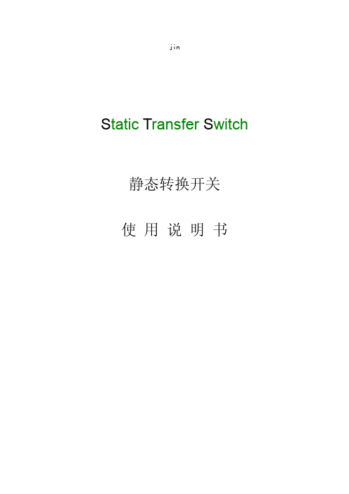
(非专业人员请勿合上维修旁路开关,以免造成故障。)
面板指示:
1.灯号、按钮说明: INPUT-A 指示灯亮(绿) :STS A 路输入正常; INPUT-A 指示灯亮(绿) :STS B 路输入正常; RUN-A 指示灯亮(绿) :STS A 路工作; RUN-B 指示灯亮(绿) :STS B 路工作; OUTPUT 指示灯亮(绿) :STS 输出正常; Fault 指示灯亮(红) :STS 异常状态; Switching:手动切换开关(本机预设 A 路优先,本按钮失效。); Mutekey:报警声消音按钮 2.转换及指示灯: 1) 当INPUT-A与INPUT-B均正常,开机3秒钟后,本装置自动将负载转到INPUT-A回路供电。 2) 若INPUT-A与INPUT-B均正常,开机3秒钟后,按面板上的手动切换开关,STS则自动切换到INPUT-B 供电。 3) 当INPUT-A正常INPUT-B异常时,热备份将由INPUT-A供电,指示灯1为亮,2为灭,5(OUTPUT)为亮, 6(Fault)亮,有报警声。 4) 当INPUT-B正常INPUT-A异常时,热备份将由INPUT-B供电,指示灯2为亮,2为灭,5(OUTPUT)为亮, 6(Fault)亮,有报警声。 5) 当负载超出设定值,静态开关将关闭,此时STS无输出。 6) 当STS有A路输入不正常时,STS以每秒一次报警,90秒后会自动消音,两路市电都正常STS自动消 音。
状况处理:
本机器仅限电工专业人员维修。请注意内部高压,非专业授权人员不得擅自打开机门检修。 机器无法顺利操作时,请先关机并检测下列步骤:
现象 无输入电源
检查方法 1. 市电输入开关是否打开? 2. 输入电源是否插妥、锁紧? 3. 输入电压是否符合额定规格?
Pulsar STS 1400 双电源切换开关说明书
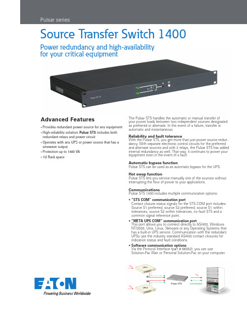
Advanced Features• P rovides redundant power source for any equipment • H igh-reliability solution: Pulsar STS includes both redundant relays and power circuit• O perates with any UPS or power source that has a sinewave output • P rotection up to 1400 VA • 1U Rack spaceSource Transfer Switch 1400Power redundancy and high-availability for your critical equipmentThe Pulsar STS handles the automatic or manual transfer ofyour power loads between two independent sources designated as preferred or alternate. In the event of a failure, transfer is automatic and instantaneous.Reliability and fault toleranceWith the Pulsar STS, you get more than just power source redun-dancy. With separate electronic control circuits for the preferred and alternate sources and with 2 relays, the Pulsar STS has added internal redundancy as well. That way, it continues to power your equipment even in the event of a fault.Automatic bypass function Pulsar STS can be used as an automatic bypass for the UPS.Hot swap functionPulsar STS lets you service manually one of the sources without interrupting the flow of power to your applications.CommunicationsPulsar STS 1400 includes multiple communication options:• “STS COM” communication portC ontact closure status signals for the STS COM port includes: Source S1 preferred, source S2 preferred, source S1 within tolerances, source S2 within tolerances, no fault STS and a common signal reference point.• “META UPS COM” communication portT his port allows you to connect directly to AS/400, Windows NT/2000, Unix, Linux, Netware or any Operating Systems that has a built-in UPS service. Communication with the redundant UPSs use the industry standard AS/400 contact closures for indication status and fault conditions.• S oftware communication optionsV ia the Protocol Interface (part # 66052), you can useSolution-Pac Wan or Personal Solution-Pac on your computer.User interface and connectionsbuzzer resetTechnical specificationsPART NUMBER 66027iNPUT Voltage 120V Frequency 50/60hzPlugs2 * Nema 5-15, 6 ft cords 2 Circuit breakers 12 amps each OUTPUT Voltage 120V Frequency 50/60hz Receptacles 6 * Nema 5-15R Circuit breakers 12 amps total TRANsfER TiME By source selector switch 4 ms By automatic switch 7 ms NO POiNT Of fAilURERelay 2 redundant relays Circuit path 2 redundant power paths Circuit breaker on Input & OutputCOMMUNiCATiONUPS#1 port / UPS#2 port STS COM / META UPS COMdiMENsiONs HxWxD 1.75 (1U)x19x9.8wEighT 5lbwARRANTy2 years (parts and labor)Pulsar STS, front viewUNITED STATES 8609 Six Forks RoadRaleigh, NC 27615 U.S.A. Toll Free: 1.800.356.5794/9135CANADAOntario: 416.798.0112LATIN AMERICABrazil: 55.11.3616.8500Caribbean: 1.949.452.9610 México & Central America: 52.55.9000.5252South Cone: 54.11.4343.6323EUROPE/MIDDLE EAST/AFRICA Denmark: 45.3686.7910 Finland: 358.94.52.661 France: 33.1.6012.7400 Germany: 49.0.7841.604.0 Italy: 39.02.66.04.05.40 Norway: 47.23.03.65.50Portugal: 55.11.3616.8500 Sweden: 46.8.598.940.00United Kingdom: 44.1753.608.700ASIA PACIFICAustralia/NZ: 61.2.9693.9366 China: 86.21.6361.5599HK/Korea/Taiwan: 852.2745.6682 India: 91.11.4223.2300Singapore/SEA: 65.6829.8888LanSafe, Eaton, ePDU, Flex, PowerChain Management, PowerTrust, Powerware,PowerPass, X-Slot, and PowerVision are tradenames, trademarks, and/or service marks of Eaton Corporation. All other trademarks are the property of their respective owners.©2009 Eaton Corporation All Rights Reserved Printed in USA STS03FXA June 2009Pulsar STS faultmain source selectPulsar STS outputsource status source OK Pulsar STS, rear viewcircuit breakersPulsar STS input STS COMMETA UPS COMUPS S2UPS S1Pulsar STS output。
双电源STS静态换转开关输入配电系统解决方案
双电源STS静态换转开关输入配电系统解决方案双电源STS静态换转开关输入配电系统解决方案(TalentPower 天普)1配置负载自动切换开关的必要性当今的市场经济和社会活动对信息网络(互联网、电信网、工业自动化控制网、政府的电子政务网站等)的依赖程度是如此之高,那怕是仅几分钟的“网络瘫痪”就可能会给公司,企业及行政管理机构的销售,经营管理、社会生活的正常运行、声誉、及公众形象带来难以估量的损失。
鉴于公众对“信息网络”的正常运营服务所期望的高度“时效性”,为此要求负责向它供电的UPS供电系统必须具有提供100%”高可利用率”的供电能力。
目前,常采用的技术措施之一是:在各种重要的信息网络机房中、配置“N+1”型UPS冗余并机系统, 从而为确保各种网络设备能安全、可靠地处理/传输/存储数据和各种信息资料创造出优良的电源运行环境。
多年来的运行实践证明:“N+1”UPS冗余并机系统具有如下技术优势:增强UPS供电系统的“容错”功能:在由“N+1”台UPS所构成的UPS冗余并机系统的运行中,如果其中某台UPS因故”出故障”时、剩下的N台UPS具有足够的”带载能力”向后接的网络设备提供纯洁的、稳压的UPS逆变器电源,从而确保各种网络设备的安全运行。
这意味着:对于这样的带“容错”功能的UPS 冗余供电系统而言,即使在遇到某台UPS因故出故障时,它仍能向它的负载提供具有100%“高可利用率”的高品质电源。
提高UPS供电系统的可靠性:例如“1+1”并机系统的平均无故障工作时间(MTBF)是UPS单机6倍左右。
如果再考虑到:当今的中、大型UPS的MTBF 值已高达40-50万小时的话,“1+1”UPS冗余供电系统的MTBF值可达250万小时左右。
同普通市电电源的99.9%的“可利用率”相比,它可将UPS供电系统的”可利用率”提高到99.99997%以上。
由此可见:它对提高供电系统的可靠性的作用是多么的巨大。
提高UPS供电系统的可维护性:它允许在UPS的逆变器电源供电的条件下、对位于UPS并机系统中的某台UPS单机执行”不带电”的定期维护/故障检修操作。
艾默生STS切换开关(16A) 说明书
用于单路供电设备的电源冗余
AC Power Systems for Business-Critical Continuity™
冗余
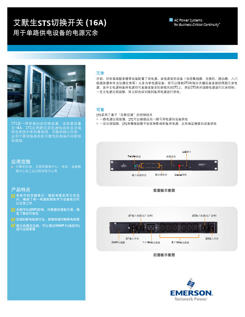
目前,仅有高端服务器等设备配置了双电源。其他类型的设备(包括集线器、交换机、路由器、入门 级服务器和专业仪器仪表等)大多为单电源设备。您可以借助STS将每台关键设备连接到两路冗余电 源,其中主电源和备用电源均可直接连接至机架框内的STS上,然后STS将对该路电源进行冗余控制。 一旦主电源出现故障,将立即自动切换到备用电源进行供电。
源2输入电缆(出厂自带)
源1输入开关
SNMP卡插槽
1个16A输出插座
6个10A输出插座
后面板示意图
源2输入开关
艾默生STS切换开关 (16A)
用于单路供电设备的电源冗余
AC Power Systems for Business-Critical Continuity™
技术指标
输入
输出 切换
环境参数
项目 工作温度 储存温度 相对湿度 海拔高度
项目 输入源 输入方式 额定电压 额定频率 电压范围 频率范围
电压失真度 功率因数 过载能力 效率(100%线性负载)
极数 自动切换间断时间
机械参数
外形尺寸(高×宽×深)
44mm×430mm×250mm
指标 两路输入源 1Ф+N+PE 220/230Vac
STS是一种单极自动切换装置,该装置容量 为16A。STS在两路交流电源构成的双总线 供电系统中承担着检测、切换的核心任务, 应用于要求极高供电可靠性的高端不间断供 电领域。
应用范围
■ 计算机机房,互联网数据中心、电信、金融数 据中心及工业过程控制中心等
毫秒级快速双电源切换开关-静态切换开关技术规范书
毫秒级快速双电源切换开关-静态切换开关技术规范书以下是毫秒级快速双电源切换开关-静态切换开关(STS)技术规范书,共计1200字以上:第一章概述1.1目的本技术规范旨在对毫秒级快速双电源切换开关-静态切换开关(STS)进行规范,确保其可靠性、稳定性和性能,以满足用户对电源切换的要求。
1.2适用范围本技术规范适用于毫秒级快速双电源切换开关-静态切换开关(STS)的设计、制造、试验和验收。
1.3术语和定义1)毫秒级快速双电源切换开关-静态切换开关(STS):一种用于自动切换电源的设备,能够在毫秒级的时间内将电路从一个电源切换到另一个电源。
2)输入电源:供应STS工作的电源。
一般包括主输入电源和备份输入电源。
3)输出电路:从STS输出的电路。
4)转换时间:从输入电源切换到输出电路的时间。
5)转换稳定性:在输入电源切换过程中,输出电路的电压和电流的稳定性。
6)额定电压:STS可以稳定工作的电源输入电压范围。
7)失效电压:STS不能稳定工作的电源输入电压范围。
第二章技术要求2.1性能指标1)转换时间:不超过10毫秒。
2)转换稳定性:在转换过程中输出电路的电压波动不超过±5%。
3)容量:能够满足用户需求的输出电流容量。
4)额定电压:在额定电压范围内,STS能够稳定工作,输出电路的电压波动不超过±2%。
5)失效电压:在失效电压范围内,STS无法保证输出电路的稳定性。
2.2安全要求1)STS应具备绝缘功能,能够防止输入电源和输出电路之间出现电流回路。
2)STS应具备过载保护功能,能够在输出电路过载时自动切断电源以防止损坏。
3)STS应具备过电压保护功能,能够在输入电压过高时自动切断电源以防止损坏。
4)STS应具备过温保护功能,能够在运行过程中温度过高时自动切断电源以防止损坏。
2.3稳定性要求1)STS的输入电源和输出电路应具备很高的抗干扰能力,能够在电磁干扰和其他干扰下保持稳定运行。
2)STS的输入电源和输出电路应具备很高的抗电压波动能力,能够在输入电压波动范围内保持稳定运行。
Liebert STS2 静态转换开关2 说明书

Color Touch-Screen Interface The color touch-screen LCD interface allows you to quickly check the status of the unit and identify problems. The controls of the Liebert STS2 are intuitive and simple. The color LCD monitor is divided into three segments. In addition to a system mimic diagram, there is a Status/Alarm panel and a section dedicated to operator instructions and menus. The screen allows you to configure the unit, including the control of the preferred source, auto/manual retransfer selection, alarm notification and other system setpoints. You benefit from improved operator effectiveness, reduced training time, and less chance of operator error.For maximum availability applications, the Liebert Static Transfer Switch2 (STS2) provides an automatic, seamless transfer between your critical load and the outputs of two independent UPS systems in a dual-bus power configuration. If the primary UPS should fail, the switch will automatically transfer the loads to the alternate UPS.Liebert is the market leader in dual-bus power systems, building the world’s most reliable UPS and Static Transfer Switch products. Liebert STS2 further extends our market leadership with design benefits unmatched by competitive products.2Standard features of theLiebert STS2 provide greateroverall protectionReliabilityy y 100% rated, fuseless design.y y Hot-swappable circuit breakers.y y Flash memory enables firmwareupdates while supportingcritical load.y y Rack-out control/powerassembly on units up to 600A toallow maintenance, service or fullreplacement without disruptingthe critical load.Flexibilityy y Internal CANBUS protocol:high-bandwidth communicationbetween system componentsvia twisted-pair cables. Optionscan be added as simplenetwork nodes.y y Dual-lug installation bus withpem nuts for single-handinstallation and “hot”torque service.Low Total Cost Of Ownershipy y Conservative design marginsand excellent overload capacity.y y UL listed.The Power to Protect Your Critical OperationsTrue Front-Access DesignAll mechanical and electronic components of the Liebert STS2 are accessible from the front of the unit for installation and service—no side or rear access required.This gives you several immediate benefits:y y Greater freedom in system design. The Liebert STS2 can be placed adjacent to or in back of other equipment. It can also be placed against a wall or partition.y y Simplified installation, with ample space for cable connections through top and bottom access plates.y y Less floor space required for maintenance access.y y Designed for maintainability, with all key components visible and accessible from thefront of the unit, without shutting down the connected load.34Figures 1 and 2Show results for the standard STS2 vs.the optimized STS2 for the samecondition (alternate source lags 120degrees) respectively. The optimizedtransfer control algorithm minimizesthe transformer saturation currentresulting from an out of phase transfer.Liebert® offers a patented optimized transfer option for the Liebert STS2 that greatly improves operation when used in primary side switching applications.The Liebert STS2 can be used in two different types of high-availability dual bus configurations—as primary or secondary side switches. For primary side switching, the unit is connected to the primary or input of a downstream transformer. On secondary side switching the Liebert STS2 is connected to the secondary or output of two transformers. One of the main advantages of using primary side switching is lower cost. These savings are the result of only one power distribution unit, a lower current due to 480V vs. 208V, and lower installation and wiring cost thanks to use of smaller three wire cable. The one drawback of this configuration is the creation of transformer inrush saturation current each time switching occurs. The downstream transformer can cause large peak saturation current during automatic transfers. The transformer saturation is caused byDC-flux built-up during transfer, especially when the sources are not in phase.Figure 1 Standard STS2 transfer Optimized Transfer Option Enhances Cost-Efficient System Operation See alsoWhite Paper: “Using an OptimizedTransfer Approach” (April 2014) at/en-US/pages/default.aspx5Liebert’s transfer control does more than balance the flux.Due to our unique approach to the optimized transfer algorithm, transfer time should not be the only performance measure for this new optimized switch. Liebert’s method, whenever possible, also seeks to minimize voltage disturbances while maintaining transformer flux balance. It takes both voltage disturbance and volt-second balance into consideration.Liebert has a unique flux balance algorithm that doesn’t just “sit and wait” for the balance point to occur. Rather, we will “pulse fire” the SCRs as soon as possible in order to minimize the load discontinuity and hence the voltage disruption.So how safe is this new optimized Liebert STS2 for your critical loads?The optimized Liebert STS2 safely meets both the CBEMA standard (prior to 1996) and the latest ITIC standard (1996) for critical loads. Liebert’s optimized STS2 minimizes the risk of transformer saturation problems during automatic transfers, while itsalgorithm control ensures minimumvoltage disturbance during transfers whilestill balancing the flux.The patented Liebert® static switch optimized transfer control algorithm significantly reduces the downstream transformer inrush saturation.The Liebert algorithm is designed to optimize transfer timing such that the volt-seconds applied to the downstream transformer primary is balanced, thusminimizing peak saturation current. This balance is achieved by directly computing the volt-second applied to the transformer during transfer events and determining the optimum time to turn on the alternate source SCRs in order to balance the volt-second within specified tolerance.This results in a volt-second balancing algorithm that is independent of voltage wave shape, voltage failure decay rate, etc., making it superior to otheralgorithms based on voltage phase angle difference only.Figure 2 Optimized STS transfer6with hinged doors to allow for easy access. The cabinet contains one vertically mounted I-line panelboard for load distribution. The panelboard is totally enclosed with an accent cover that provides access without exposing other portions of the unit. The panelboard provides space for 100A through 250A three-pole branch circuit breakers. It also includes a separate isolated neutral bus bar and safety-ground bus bar for the neutral and safety-ground connections.Redundant Output Breaker: An output plug-in, non-automatic circuit breaker provides redundancy in the output power path. The breaker is connected in parallel with the output plug-in non-automatic circuit breaker.Input Junction Boxes and Cable (Up to 600A): The input junction box option is available to simplify input connections to the STS2. Two input junction boxes and the associated flexible 10-foot long input cables are provided with this option. Available with bottom cable entrance only, typically when the unit is located on a raised floor.Remote Source Selection: An optional Remote Source Selection board may be installed in your STS2. This option allows you choose the preferred input source from a remote location. Terminal connections enable you to remotely select a preferred source in the same process as the local source transfer selection. Key Lockout Switch: The key lockout switch activates a software lockout of the touch-screen display to prevent manual transfers and configuration changes. When locked out, the touch-screen becomes a read only display. A key is needed to perform manual transfers or change settings.Liebert® STS2 Communication and Product OptionsLiebert STS2 has a wide choiceof monitoring and communicationsoptions to keep you connectedto your critical powerprotection system.RS-232 Terminal Port: Standard on allunits, this port is primarily used as analternate user interface to configure,control, and diagnose the system.Input Contact Isolator (ICI) Board:Customizable input relays allow alarmsfrom other devices to be displayed onLiebert STS2 display. Provides aninterface for up to eight user inputs.External messages and alarms can berouted to the unit, via the ICI.Programmable Relay Board (PRB):Programmable output relays for customcustomer alarms and connections. Upto two PRBs can be installed in theLiebert STS2 to route system eventsto external devices.Comms Board: This board provides adirect connection to a Liebert SiteScan®Web system, via an RS-422. SiteLink-12 orSiteLink-4 is required for SiteScan tocommunicate with the Liebert STS2.Options and AccessoriesSeismic Anchors: To ensure stability forthe unit in the event of seismic activity,anchors are available for securing the unitto a concrete floor to meet seismicZone 4 requirements.Seismic Floor Stand: Designed to levelthe unit and provide bottom cablingaccess without relying upon a raised floorfor support. Available in 18, 24,30, 36 inch heights.Distribution Cabinet (Up to 600A): Anoutput distribution cabinet mounts on the side of the STS2. It is a full height sectionLiebert IntelliSlot™ 485 Web Card ADPT y y Allows systems to be viewed from the network using a web browser. y y Delivers SNMP, Telnet and web management. y y Provides security using HTTPS message encryption. y y Supports 10 and 100 MBit Ethernet for legacy and modern networks.y y Provides compatibility with Liebert MultiLink shutdown software, to prevent data loss and ensure data availability. y y Supports Liebert SiteScan WEB enterprise monitoring software, to provide trending for proactive analysis and maintenance to ensure facility uptime. y y Interfaces to Liebert Nform alarm notification software, to facilitate quick corrective action. Liebert IntelliSlot 485 Web Card ADPT provides connectivity to any TCP/IP-based Ethernet network to allow the device to communicate with network management systems (NMS) via SNMP. Events can be transmitted to the NMS to provide remote status monitoring, plus fault and alarm detection. The card includes an RJ-45 port for an Ethernet connection, via Category 5 cable. The card can also integrate the system with an existing Building Management System (BMS) or out-of-band monitoring,using Modbus.Specifications(KW)(inches)(mm)(lbs)(kg)(inches)(mm)(lbs)(kg)1000.830x32x77762x813x1956780 35448x44x821016x1194x2082880399250 1.3730x32x77762x813x195678035448x44x821016x1194x2082880399400 2.0438x32x77965x813x1956120054448x44x821016x1194x20821300590600 3.0838x32x77965x813x1956120054448x44x821016x1194x20821300590800 4.0384x32x772134x813x19562500113492x53x822337x1346x2082260011791000 5.0984x32x772134x813x19562500113492x53x822337x1346x208226001179Note: ¹Shipping dimensions and weight include the pallet and packing material. Actual weights will vary depending on installed options.7Continuous 24-hour remote monitoring of UPS/power conditioning equipment, environmental products and other critical space support systems is available. No matter where your facilities are located, we can provide continuous oversight of a wide range of critical installations from our Customer Response Center. When a problem is detected, the monitoring system immediately alerts the Customer Response Center where each alarm is evaluated and processed. The center offers instant phone assistance using a customer-defined response and call escalation plan. Liebert will coordinate all service vendors, track the response and solution time for service calls and provide comprehensive reports on alarms and corrective actions.schematics and your equipment’s complete service record from the time it was started up.Remote Monitoring — Always There, Always Alert The key to providing proper service for your critical power systems is being aware of that equipment’s operating status atany given time. For customers who need to have these vital protection systems continuously monitored, but don’t want to do it themselves, Vertiv Service offers Remote Monitoring Service. This seamless, rapid-response system is designed to maximize the capabilities of your Liebert equipment by maximizing the effectiveness of its monitoring capabilities.Critical Space Support from Vertiv™ ServiceTotal Service Capability Vertiv provides a Basic, Essential and Preferred level of maintenance and service that allows you to select the complement of critical power system services that best fits your requirements.These programs include guaranteed four-hour response time, emergency service and preventive maintenance. With more than 300 Liebert-employed Customer Engineers and a network of over 900 factory authorized service personnel, our technical capabilities, geographical coverage and ability to respond are second to none. These factory-trained service professionals have direct access to the most comprehensive factory authorized parts network in the industry. We also provide them withimmediate online access to detailedOperating SpecificationsVoltage: 208, 220, 240, 380, 400, 415, 480 or 600 VAC (field selectable), +/- 10%Frequency: 50 or 60 Hz (field selectable), +/- 0.5 HzOverload Capability: 125% for 10 minutes,150% for 2 minutesOperating Temperature: 0 to 40° C。
(产品管理)STS静态转换开关产品描述及技术参数
(产品管理)STS静态转换开关产品描述及技术参数STS静态转换开关产品描述及技术参数壹、产品描述静态转换开关(StaticTransferSwitch)能够实现不同输入电源之间的不间断切换,为单电源负载提供双母线供电如:*非且联UPS系统的n+1冗余*不同容量UPS系统的n+1冗余*不同型号UPS系统的n+1冗余功能俩个独立输入源之间的快速转换转换时间转换时间典型值1,8ms/每相最大.5ms相单独转换模式三相同时转换模式转化瞬间源于源之间没有环流有序的转换按照顺序,每相于电流过零点的时候发生转换自动和手动转换✧转换由内部逻辑或外部命令控制。
✧自动转换发生于被选择的源超出其允许精度范围的时候。
✧手动转化是通过前面板的按钮开关或UPS输入的控制命令来实现的。
二、技术参数APOTRANS25-63AAPOTRANS125-1000A一、PillerAPOTRANSAT系列转换开关原理框图1.PillerAPOTRANSAT系列25A~63A2.PillerAPOTRANSAT系列125A~1600A二、PillerAPOTRANSAT系列转换开关工作方式PillerAPOTRANS静态转换开关采用最新的电源技术和先进的数字控制,为用户提供最佳解决方案。
该系统可实现俩个相同的电源之间或不同的电源(如不同型号、品牌的UPS)之间的不间断转换。
俩路输入电源中的壹路通过静态开关和负载连接,当这路发生故障时就会自动切换到另外壹路输入电源。
静态开关SS1和SS2通过Q1、Q2、Q3三个手动开关和负载且联,另外,俩路输入电源和负载的连接是通过俩个维修旁路开关。
正常工作方式下,Q1、Q2、Q3闭合,Q4、Q5断开。
预设定的输入电源通过可控硅开关和负载连接,若该路输入发生故障或输入电压无法满足要求时,系统会自动切换到另外壹路输入电源。
系统要恢复到预设定的输入电源,将取决于用户对系统的设置。
于特定条件下的自动切换,可通过操作面板上的控制键或外部信号实现手动转换。
- 1、下载文档前请自行甄别文档内容的完整性,平台不提供额外的编辑、内容补充、找答案等附加服务。
- 2、"仅部分预览"的文档,不可在线预览部分如存在完整性等问题,可反馈申请退款(可完整预览的文档不适用该条件!)。
- 3、如文档侵犯您的权益,请联系客服反馈,我们会尽快为您处理(人工客服工作时间:9:00-18:30)。
小于 10ms
4
5
东莞市科风电子有限公司
DongGuan KengFeng Electronic Co.,Ltd
STS 双电源静态切换开关使用说明
STS static transfer switch of power instruction manual
�STS 简介……………………………1 �电力 STS……………………………3 �技术参数…………………………...4 �典型应用…………………………...5
性能特点
》采用电力标准配置要求,工业级设计生产; 》采用 DSP 数字化控制技术和完美的保护功能,实现超强的稳定性; 》采用日本原装进口 NELL 品牌的 SCR 模块设计,极强的过载及抗冲击能力; 》具有过压,欠压,过流等保护功能。
负荷快转移
》本系列产品采用的是同步控制技术与高采样模块,确保了切换时的同步一致性。DSP 数 字化智能控制芯片确保功率部件安全可靠快速的切换,保证负载供电安全。
1
DSP 控制芯片
日本原装进口 SCR 模组
STS 安装图 2
STS 接线端子
电力 STS
25A-100A
电力 STS 是针对中国 A 级机房要求设计的一款高性能与高性价 比的高端产品。经全新数字技术研发的第二代快速负荷切换开关。 系 统采用延时拓扑衔接架构组成。完全实现切换时间的精确性,完美地 转移负荷。电力系列 STS 拥有高性能的保护,提升了系统运行安全、 可靠性。本着运行安全高于一切的应用理念,电力系列 STS 无疑是 您最佳的选择。除上述以外,电力系列 STS 还具有带载能力强,发 热低等优点。
应用领域
�中大型机房环境; �中大型通信机房; 3 �中大型配电房; �中大型工作站及外围设备。
技术参数
标准容量 额定电流 切换时间 输出接口 优先级 主路输入电压范围 输入 备路输入电压范围 输入频率范围 输出电压范围 输出 管理 保护 环境 物理特性 输出过流 输出效率 控制技术 过载短路保护 环境温度 环境湿度 机箱尺寸 机箱重量 5.5KW 25A 11KW 50A 端子台 主路 200V~240V 200V~240V 45HZ~55HZ 200V~240V 125% >98% DSP 数字控制 过流保护器 0℃-50℃ 10%-90% 300*380*210 25kg 13.8KW 63A 22KW 100A
