蓝牙转CAN模块GCAN-203 用户手册
CAN总线中继模块GCAN-206用户手册

钮卸载安装好的设备驱动。 用户可通过“添加/删除程序”中找到 ECANTools 软件对其进行卸载。
产品数据手册
8
沈阳广成科技有限公司
工业级 CAN 总线中继器--GCAN-206
2.3 接口定义及功能
GCAN-206 模块集成 1 路 DC 24V 电源接口、2 路标准 CAN-Bus 接口。 GCAN-206 模块接线端子排如图 2.3 所示。
图 2.3 GCAN-2ቤተ መጻሕፍቲ ባይዱ6 模块接线端子排
GCAN-206 模块的电源接口由 1 个 4Pin 插拔式接线端子引出,其接口定义 如表 2.1 所示。
GCAN-206
CAN总线中继模块
用户手册
文档版本:V3.2 (2018/07/18)
沈阳广成科技有限公司
修订历史
版本 V1.00 V2.01 V3.01 V3.2
日期 2013/06/16 2013/12/20 2015/04/22 2018/07/18
工业级 CAN 总线中继器--GCAN-206
产品数据手册
4
沈阳广成科技有限公司
1.3 典型应用
汽车电子网络 电力通讯网络 工业控制网络 高速、大数据量通讯
工业级 CAN 总线中继器--GCAN-206
产品数据手册
5
沈阳广成科技有限公司
工业级 CAN 总线中继器--GCAN-206
2. 设备安装
2.1 设备尺寸
设备外形尺寸:(长,含接线端子)112mm * (宽)99mm * (高)22mm,其示意图 如图 2.1 所示。
GCAN-207 RS232,485转CAN(CANCOM) 用户手册

GCAN-207高性能工业级RS232/485-CAN转换器用户手册文档版本:V3.60(2018/07/18)修订历史版本日期原因V1.002013/06/16创建文档V2.012013/12/20修正设备工作参数V3.012014/10/22添加部分参数V3.062015/09/09添加部分功能说明V3.502016/09/11添加部分参数V3.602018/07/18调整文档结构目录1功能简介 (4)1.1功能概述 (4)1.2性能特点 (4)1.3典型应用 (5)2设备安装 (6)2.1设备尺寸 (6)2.2接口定义及功能 (6)3设备使用 (8)3.1与PC连接 (8)3.2串口连接 (8)3.3CAN连接 (8)3.3CAN总线终端电阻 (9)3.4系统状态指示灯 (9)4配置说明 (11)4.1配置准备 (11)4.2软件连接 (11)4.3配置转换参数 (12)4.4配置串口参数 (14)4.5配置CAN参数 (15)4.6配置完成 (16)5应用实例 (17)5.1透明转换 (17)5.2透明带标识转换 (20)5.3格式转换 (25)6使用注意 (27)7技术规格 (28)8常见问题 (29)附录:CAN2.0B协议帧格式 (30)1功能简介1.1功能概述GCAN-207(CANCOM)是集成1路标准CAN-bus接口、1路标准串行接口(RS-232/RS-485)的工业级CAN-bus与串行总线通讯连接器(网桥)。
采用GCAN-207模块,用户可以将原本使用RS-232/RS-485总线进行通讯的设备,在不需改变原有硬件结构的前提下使其获得CAN-bus通讯接口,实现RS-232/RS-485通信设备和CAN-bus网络之间的连接,构成现场总线实验室、工业控制、智能小区、汽车电子网络等CAN-bus网络领域中数据处理、数据采集的CAN-bus网络控制节点。
GCAN-207模块在正常工作时,处于实时对CAN总线和RS-232/RS-485总线进行监听的状态,一旦检测到某一侧总线上有数据接收到,立即对其进行解析,并装入各自的缓冲区,然后按设定的工作方式处理并转换发送到另一侧的总线,实现数据格式的转换。
GCAN-208CAN光纤转换器用户手册
GCAN-208CAN光纤转换器⽤户⼿册GCAN-208CAN光纤转换器⽤户⼿册⽂档版本:V3.01 (2015/8/4)修订历史⽬录⽬录 (3)1. 功能简介 (4)1.1 功能概述 (4)1.2 性能特点 (4)1.3 典型应⽤ (5)2. 设备安装 (6)2.1 模块固定 (6)2.2 光纤连接 (8)2.3 与CAN总线连接 (8)3. 设备使⽤ (9)3.1 CAN总线配置 (9)3.2 与光纤连接 (10)3.3 与CAN连接 (10)3.4 CAN总线终端电阻 (11)3.5 系统状态指⽰灯 (11)4. 技术规格 (13)5. 常见问题 (14)附录CAN2.0B协议帧格式 (15)1. 功能简介1.1 功能概述沈阳⼴成科技有限公司GCAN-208模块是集成1路标准光纤接⼝(单模、多模,SC、ST可选)、2路标准CAN总线接⼝的⼯业级CAN总线转光纤转换器。
GCAN-208模块可以将CAN总线数据转换成光信号通过光纤传输。
通过成对使⽤GCAN-208模块,⽤户可以轻松的延长CAN总线通信距离、有效的消除长距离通信⼲扰,可以防⽌总线受到电磁⼲扰、地环⼲扰、雷击等对总线和设备造成的损坏。
GCAN-208模块可将CAN总线数据透明、⽆损的转换成光信号,再将光信号透明、⽆损的解析成CAN总线数据。
⼴成科技使⽤独有的总线信号转换技术,可将CAN数据与光信号之间的转换时间做到微秒级,这样就保证了通信的实时性,所以GCAN-208可⽀持任何CAN总线通信协议如:CANopen、SAE J1939、DeviceNet、NMEA2000等等。
GCAN-208模块独特的双通道设备可以同时延长两条CAN总线的通信距离,该模块是⼯业总线改造、长距离通信、隔离总线⼲扰的关键性⼯具,同时该模块具有体积⼩巧、即插即⽤等特点,也是现有系统集成的最佳选择。
GCAN-208模块的总线接⼝已集成隔离保护模块,使其避免由于瞬间的过压过流⽽对模块造成损坏。
EB203蓝牙说明书-cn

多功能无线立体耳机用户文档1.参数2.按键、接口、开关3.使用教程on/off(开关),把开关推向on,耳机将随之启动。
耳机默认进入蓝牙模式,耳机指示灯蓝灯闪烁。
通过M键来进行功能切换,播放MP3,FM收音功能,关机状态充电(红灯)。
3.1.蓝牙1)蓝牙模式,指示灯蓝灯长亮(或根据提示语言指引操作)。
耳机蓝牙功能已经开启,正在等待连接状态。
此时蓝牙耳机已处于可被查找状态。
2)点击手机设置中的蓝牙设置,选择“开启”完成。
这就打开了手机的蓝牙功能。
3)打开手机上的蓝牙选项,进行查找,成功搜索到等待配对的蓝牙,可用设备列表上显示EB203。
点击 EB203即可连接,此时耳机上指示灯只有绿灯闪烁,表示已经连接成功。
注意:部分手机连接,提示需要输入密码12343.2.TF卡播放将TF 卡插入到耳机卡糟中,按M键切换至读卡模式,指示灯绿灯闪烁。
系统自动解码可以播放的音频格式文件,此时你钟爱的悠扬歌声轻轻响起。
3.3.FM电台按M键切换至读卡模式,指示灯红灯闪烁。
此时可能听到咝咝声,这表示没有电台,只需按下键,耳机将会自动搜索电台节日。
短按键和键可以切换上下电台频道。
4.充电充电前,关闭耳机电源,将充电线使耳机与电脑USB连接,此时耳机指示灯以红色着亮。
表示USB连接成功,耳机正在充电。
系统内置电池容量检测与过载保护。
无需担心充电时间长对电池的影响。
指示灯自动熄灭,表示充电已经完成。
电量低--电量低时红灯闪烁,请尽快充电,这样才能满足蓝牙系统需求。
注意:充电过程中请不要打开耳机电源,否则损伤耳机硬件和电池寿命。
5.注意事项1)这款耳机不防水,请注意防水和防潮,以确保该系统可以正常使用。
2)它主支持电脑USB接口充电,不要改变或将其连接到外部其它电源充电。
3)耳机不可以长期放置,请每周一次充电和放电,从而延长电池寿命。
商业级袖珍型接口转换器UT-203说明书

五、通信连接示意图RS-232RS-422至转换UT-203UT-2031RS-422/、点到点四线全双工通信2RS-422/、点到多点四线全双工3UT-203、接口转换器之间全双工通信连接UT-203RS-422设备UT-203RS-422设备RS-422设备RS-422设备RS-232/RS-485/RS-422UT-203商业级袖珍型接口转换器使用说明书为了便于配有不同标准串行接口的计算机、外部设备或智能仪器之间进行远程数据通信,必须进行标准串行接口的相互转换。
转换器兼容、、标准,能够将单端的信号转换为平衡差分的或信号,转换器可将通信距离延长至公里,无需外接电源采用独特的“电荷泵”驱动,不需要靠初始化串口可得到电源,内部带有零延时自动收发转换,独有的电路自动控制数据流方向,而不需任何握手信号如、等,无需跳线设置实现全双工、半双工模式转换,从而保证了在全双工、半双工方式下编写的程序无需更改便可在方式下运行,确保适合现有的操作软件和接口硬件,转换器传输速率都可以应用于主控机之间、主控机与单片机或外设之间构成点到点、点到多点远程多机通信网络实现多机应答通信广泛地应用于工业自动化控制系统、一卡通、门禁系统、停车场系统、自助银行系统、公共汽车收费系统、饭堂售饭系统、公司员工出勤管理系统、公路收费站系统等等。
RS-232C RS-485RS-422RS-232RS-485RS-422RS-232 1.2RS-232RS-232I/O (RTS DTR )(RS-422)(RS-485)RS-232RS-422/485300-115.2Kbps.,.一、概述1EIA/TIA RS-232C RS-485/RS-4222RS-232DB9RS-485/422DB9345300BPS-115.2KBPS663mmX33mmX17mm7-25705%95%81,200RS-4855RS-232、接口特性:接口兼容的、标准、电气接口:端孔型连接器,端针型连接器,配接线柱、工作方式:异步全双工、半双工差分传输自动选择,无需跳线设置、传输介质:双绞线或屏蔽线、传输速率:、外形尺寸:、使用环境:℃到℃,相对湿度为到、传输距离:米(端)米(端)二、性能参数123DB-9/DB-9,++--++--RS-485T/R+A+T/R-B-RS-422T/R++RXD++T/R--RXD--RXD++TXD++RXD--TXD--本产品外形采用通用转接插头,输出接口配有普通接线柱可使用双绞线或屏蔽线,连接、拆卸非常方便。
T230说明书

您好:感谢您选择本公司生产的数字移动电话。
天语,您无线通信的最佳伙伴,无论您身处何时何地,都可以和您的亲朋挚友“keep in touch”。
清晰保真的通话音质、方便快捷的短信让您的通信随心所欲。
与您携手探索生活的无限可能与重重惊喜。
拥有天语,让您的沟通永不止步!通过阅读本手册,您可以全面地了解本手机的使用。
注:如果本用户指南中所述的功能与产品的实际功能有所不符,请以菜单查找指南和产品的实际功能为准。
本公司保留在不作任何预先通知的情况下对本手册中内容作修改的权利,恕不另行通知。
手机绑定说明本手机支持3G上网业务,为您提供更方便、更快捷的上网体验。
您可以直接通过手机上网,也可以将手机连接到电脑上,手机本身充当TD上网卡,通过电脑上网。
在使用TD上网前,您需要做SIM卡和上网卡的绑定操作,具体操作如下:1. 绑定触发场景:◆绑定,可按手机提示操作,完成绑定;◆电脑上网时,将手机通过数据线连接到电脑,在手机提示下选择示您进行绑定,可按手机提示操作,完成绑定。
2. 3G网络开关说明无论通过手机还是电脑上网,您必须开启3G网路,具体操作如下:◆◆开启3G 网络开关。
3. 去绑定、套餐变更流程作。
4. 关于绑定功能失效说明◆当您购买此款手机后但从未产生绑定关系,手机的绑定功能将在2011年12月31日失效;如果绑定功能失效,请及时与当地天语售后中心联系,申请重新开启3G上网业务,切勿自行拆卸。
◆去绑定后连续6个月未产生绑定关系(含业务暂停),手机绑定功能失效。
如果绑定功能失效,请及时与当地天语售后中心联系,申请重新开启3G上网业务,切勿自行拆卸。
注意在以下几种情况时,请先解除绑定:◆在注销SIM卡之前,请先解除绑定!!!◆当转赠他人时,请先解除绑定!!!◆如手机丢失,请去当地移动营业厅解除绑定!!!1、安全预防措施..........................................................错误!未定义书签。
ModbusRtu转CAN模块 GCAN-204 用户手册

Modbus RTU-CAN转换模块
用户手册
文档版本:V3.25 (2018/07/18)
沈阳广成科技有限公司
修订历史
版本 V1.00 V2.01 V3.01 V3.02 V3.23 V3.25
日期 2013/6/16 2013/12/20 2014/10/22 2015/08/08 2017/03/22 2018/07/18
5. 应用实例.................................................................................................................16 5.1 读取接收到的 CAN 帧................................................................................ 16 5.2 写入要发送的 CAN 帧................................................................................ 16
GCAN-204 模块是工业总线改造,多种总线设备互连的关键性工具,同时该 模块具有体积小巧、即插即用等特点,也是现有系统集成的最佳选择。GCAN-204 的各种总线接口均集成隔离保护模块,使其避免由于瞬间的过压过流而对模块造 成损坏,使用 DIN 导轨的固定方式,使其更容易集成到各种控制柜中。
1.2 性能特点
6. 使用注意.................................................................................................................18 7. 技术规格.................................................................................................................19 8. 常见问题.................................................................................................................20 附录 A:CAN2.0B 协议帧格式.................................................................................21 附录 B:Modbus 协议简介........................................................................................ 23
GCAN-203 Bluetooth-CAN converter User Manual
GCAN-203Bluetooth-CAN converterUser manualDocument version:V3.20(201704/09)Contents1.Introduction (1)1.1Overview (1)1.2Properties at a glance (1)2.Installation (1)2.1Power connection and indicator status (1)3.CANBlue config software (2)3.1Configuration (2)3.2Software connection (2)3.3CAN parameter setting (3)3.4Bluetooth parameter settings (5)3.5End of configuration (6)3.6Save the configuration file (6)3.7Open the configuration file (6)4.Application examples (7)4.1Equipment wiring (7)4.2Bluetooth connection (7)5.Technical specifications (11)Appendix:GCAN-203data flow definition (12)1.Introduction1.1OverviewGCAN-203has a standard CAN-Bus interface.GCAN-203can send CAN-Bus date to other equipment with Bluetooth.1.2Properties at a glance●CAN-Bus baud rates range from5Kbps to1Mbps●CAN-Bus isolation module insulation voltage:DC1500V●Maximum data traffic:300frames per second●Bluetooth using2.0●Power supply:9~30V(20mA,24V DC)●Installation method:DIN rail●Working temperature range:-40℃~+85℃;●Size:(L)112mm*(W)70mm*(H)25mm.2.InstallationGCAN-203interface shown in figure2.1.Figure2.1GCAN-203interface definition2.1Power connection and indicator statusGCAN-203recommends using standard24V power supply.GCAN-203has three indicator lights,1PWR,1SYS,1CAN.The functions of the three indicators are shown in table2.2,the indicators in different states,the converter status shown in table2.3.3.CANBlue config software3.1ConfigurationDisconnect the GCAN-203power supply.We can connect to GCAN-203and computer with USB.When GCAN-203is configuring,no external power is required. GCAN-203factory setting:CAN-Bus baud is250K,working mode is normal mode, name is SN number,password is1234.3.2Software connectionOpen"CANBlue Config"software in the"②CANBlue模块配置软件"document to configure the converter.Click"Connect"to connect the converter.The connection is shown in figure3.1.You can click"UpLoad"to upload the parameters in the converter to your computer.Figure3.1CANBlue Config software interfaceFigure3.2CANBlue Config software upload parameters3.3CAN parameter settingClick"CAN Param"to enter CAN communication parameter setting.We can click"CAN Baud"to configure the baud rate of the CAN-Bus,as shown in the followingFigure3.3CAN baud rate settingThe default value of“CAN Mode”or“CAN Filter”is set to0,and please do not change it.Figure3.4CAN operating mode setting3.4Bluetooth parameter settings Click"Bluetooth Param"to enter the Bluetooth parameter settings.Figure3.5Bluetooth settingsThe user can set the GCAN-203's name and connection password.GCAN-203's default name is SN number,password is1234.3.5End of configurationClick"Download"to write the configuration data to the converter's flash,as shown in figure3.6.Figure3.6Download successfulThe pop-up dialog displays"download Param success".Then power-on again.The new configuration can take effect.Note:The converter must be power-on again,otherwise the configuration will not take effect.3.6Save the configuration fileClick“SaveAs”to save the configuration parameters to the PC.The file can be opened again.3.7Open the configuration fileUse the“OPEN”function to open the configuration file and modify it.Then you can click DownLoad to the converter that the new configuration can be saved.Note:The working mode of“BlueTooth Test”and“CAN Test”is used for testing. These functions cannot be used.4.Application examples4.1Equipment wiringGCAN-203uses9-30V DC power supply.Connect CAN_H to CAN-Bus CAN_H,CAN_L to CAN-Bus CAN_L.A High-speed CAN bus must be terminated on both ends with120Ohms.Otherwise disturbances may arise.Figure4.1The wiring diagram of GCAN-203As shown in figure4.1,the left side of the equipment is USBCAN-II Pro.Wiring and termination resistance must be confirmed correctly.Open USBCAN-II Pro equipment with ECANtools software,then select the baud rate to250K.4.2Bluetooth connectionInstall"CANBlue.RSO.apk"APP to a mobile phone with android which is in the"③安卓系统串口助手安装包"document.Search for Bluetooth equipment,then enter the connection password.4.3Bluetooth serial assistant use4.3.1Connect to GCAN-203Open the software,the interface is shown in figure4.2.The function of the four buttons will be shown here:蓝牙开关——Turn on Bluetooth or turn off Bluetooth.搜索设备——Click“搜索设备”.You can find all the converters that opened Bluetooth,only the converter name turn blue can be connected.(GCAN-203's default name is SN number,password is1234)版本升级——Not open yet.侦听连接——Not open yet.Enter the receive/send data interface,as shown in figure4.3.Figure4.2Software interfaceFigure 4.3Main interface for sending and receiving data4.3.2Send and receive data for exampleThe following is a brief introduction to the received /sent data format.Please refer to the appendix for detailed data format.The CAN frame Information(FF,RTR)represents the frame format and frame type of the CAN frame.The specific values are shown in the following table;the CAN frame Information (DLC)represents the byte length of the CAN frame data.According to the actual needs ,it fills 0to 8.Example of special data transmission:table 4.1.1.The mobile equipment sends data to the CAN terminal,DLC is 2bytes less than 8bytes of data(1122334455667788),CAN receives 2bytes of data (1122).2.The mobile equipment sends data to the CAN terminal,DLC is 8bytes more than 4bytes of data(11223344),CAN receives 8bytes of data (11223344XX XX XXXX)(XX is used for the filling,which is meaningless).3.CAN sends data to the mobile equipment,and CAN terminal sends4bytes of standard data frame(11223344).The mobile equipment receives8bytes of frame data(11223344XX XX XX XX)(XX is used for the filling,which is meaningless). ArrayTable4.1Example of special data transmission5.Technical specificationsRepresentation of extended frame ID Representation of standard frame ID0X123456780X123written with 0.Otherwise it will lead to communication error.。
GCAN-302-XS SICK P30转CAN用户手册
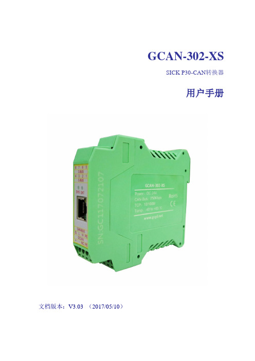
GCAN-302-XSSICK P30-CAN转换器用户手册文档版本:V3.03 (2017/05/10)修订历史目录1. 功能简介 (4)1.1 功能概述 (4)1.2 性能特点 (4)2. 设备安装 (5)2.1 设备安装 (5)2.2 与以太网连接 (6)2.3 与CAN总线连接 (6)3. 设备使用 (7)3.1 与以太网连接 (7)3.2 与CAN连接 (7)3.3 CAN总线终端电阻 (8)3.4 系统状态指示灯 (8)3.5 节点ID设置 (9)3.6 升级程序设置 (10)4. 转换协议格式 (11)4.1 配置网关IP (11)4.2 数据转换说明 (12)5. DMP传感器协议 (13)5.1 CAN帧ID说明 (13)5.2 CAN帧数据说明 (13)6. 技术规格 (14)1.功能简介1.1 功能概述GCAN-302-XS转换模块是集成1路标准CAN接口、1路SICK P30接口的高性能通讯模块。
GCAN-302-XS专用于SICK P30设备与CAN总线的连接。
GCAN-302-XS模块是一个简单、直观的节点组态工具,现已被广泛应用于构建现场总线实验室、工业控制网络、智能小区监控、变频器改造等多种环境中。
该设备具有体积小巧、即插即用等特点,同时该模块使用DIN导轨的安装方式,使其特别适用于工业现场或机柜中与其他设备配套使用。
GCAN-302-XS模块已集成CAN接口电气隔离保护模块,使其避免由于瞬间过流/过压而对设备造成损坏,增强系统在恶劣环境中使用的可靠性。
1.2 性能特点1.2.1 硬件特点●高速的32位工业级处理器;●内嵌硬件看门狗定时器;●模块内置FLASH储存器,可储存参数、映射表;●使用外接电源供电(DC+24V,40mA);●静电放电抗扰度等级:接触放电±2KV,空气放电±15KV;●电快速瞬变脉冲群抗扰度等级:±1KV;●浪涌抗扰度等级:±1KV;●工作温度范围:-40℃~+85℃;●工作湿度范围:5%~95% RH无凝露;●尺寸:(长)113mm * (宽)100mm * (高)21mm;●标准DIN导轨安装方式,专为工业设计。
RT203快速用户指南说明书

Thank you for choosing RTscan, this guide will help you to use RT203 easily.Index1. USB-HID KBW (2)2. USB-COM (USB COM Port Emulation) (4)3. RS232 Serial Port (7)4. TTL Interface (10)5. Instruction Documents Download (11)6. Programming Video Guid e (11)1. USB-HID KBWIf your RT203 come with USB interface, the default setting is USB-HID KBW, it's plug and play, connect the scanner with your computer and run Notepad / MS Word, after reading the barcode, the decoded data will be shown there.For the connection of the connector, pl ease refer to the picture bel ow.2. USB-COM (USB COM Port Emulation).If your RT203 come with USB-COM (USB COM Port Emulation), you will need to have a software that can work with a virtual serial port to test the scanner.You can use your own Virtual Serial Tool, or download the Virtual Serial Tool at the following link :https:///open?id=1djokTmXZJAlDSehhI_7EMugiCazIkP5NPlease do the foll owing steps to use the read er with USB Virtual COM.① Connect the reader with your PC or terminal.② In most cases, the computer will install the driver automatically, if not, please contact our sales to get the driver.③ Confirm the COM port number at Device Manager as below picture, below is the COM13.④ Run a virtual serial port tool, then pick the exact COM port number (like the below is COM10) and also the correct baud rate 115200 (default baud rate is 115200).For the connection of the connector, please refer to the picture below.3. RS232 Serial PortIf your RT203 come with RS232 interface, you will need to have a software that can work with a serial port to test the scanner.You can use your own Virtual Serial Tool, or download the Virtual Serial Tool at the following link :https:///open?id=1djokTmXZJAlDSehhI_7EMugiCazIkP5NPlease do the foll owing steps to use the read er with RS232 serial port.① Connect the reader with your PC or terminal.② Confirm the COM port number at Device Manager as below picture, below is the COM13.③ Run a virtual serial port tool, then pick the exact COM port number (like the below is COM13) and also the correct baud rate 115200 (default baud rate is 115200).For the connection of the connector, please refer to the picture below.PS: If you use the scanner with USB cable (USB-HID KBW) firstly, and want to change it with RS232 cabl e, please scan bel ow setting cod e on USB-HID KBW mode before connect the RS232 cabl e.For all of Default serial communication parameters and baud rate setting, same with above for “USB COM Port Emulation”4. TTL InterfaceIf your RT203 come with TTL interface, for the connection of the connector, please refer to the picture below.You can kindly d ownl oad the instruction documents of read er at the foll owing link : https:///open?id=1QoUK7G5l1HOHdunJ66zkjszgD1jaLkRQ Inclused:●Integration Guide●User Manual●Programming Command Guide●Drawing6.Programming Vid eo Guid eYou can program the barcode reader by commands, kindly refer to our video guid e as below.https://youtu.be/LsX7aeaME00 -------Command programming guideYou can also program the barcode read er by setting codes , kindly refer to the RT203 User Guide.If you need any other technical support from RTscan, please feel free to contact us:*****************, thank you!。
CAN协议转换板使用说明

如果不能确保烙铁接地良好,可以在烙铁热起来后,拔掉烙铁插头再进行焊接。 烙铁温度不宜太高,焊接与地相连的过孔时可以适当高一些 除非不得已,千万不要直接在单片机引脚上直接引线,通常这些引脚都可以在PCB上找到大
音响控制手柄
CAN总线
协议板外观
接线说明
+12V GND CAN_H CAN_L 未连接 未连接
串口地 RS232串口接收 RS232串口发送
指示灯位置
绿色电源指示灯
绿色运行指示灯 红色数据发送指示灯 橙色数据接收指示灯
指示灯说明
板子上电后,所有的指示灯都点亮。电源指示灯上电后保持常亮 上电0.5秒左右后,运行灯、发送指示灯、接收指示灯依次熄灭。 随后运行灯开始闪烁,标识板子启动完毕 当CAN总线有报文送达时,接收指示灯闪烁 当板子向往发送数据时,发送指示灯闪烁
CAN协议转换板使用说明书
功能介绍
CAN协议转换板可以将来自CAN总线的数据转发至RS232异步串口上;同时也可以将RS232 串口上的数据转发至CAN总线上,从而完成协议转换。
有了CAN协议转换板,不具备CAN收发功能的设备就可以通过RS232连接至CAN网络,进行 数据收发。
307智能行车辅助系统需要通过CAN协议转换板接入车辆的舒适总线,从而完成车辆状态的 读取和对车辆的控制。
12V输 入GND
ACC
电源模块
12V输 出地
12V输 出地
主板12V 输出
主板
Power ORenset
Байду номын сангаасGND
协议板
串口设置范例
RGBlink MSP 203 视频转换器用户手册说明书
MSP 203用户手册●文件编号:RGB-RD-UM-M203 C001●版本:V1.3MSP 203·用户手册首先感谢您选购我们的产品!为了让您迅速掌握如何使用这款视频转换器,我们为您送上了详细的产品使用手册。
您可以在使用视频转换器之前阅读产品介绍以及使用方法,请仔细阅读我们所提供给您的所有信息,以便于您正确地使用我们的产品。
版权©2012所有版权归厦门视诚科技有限公司所有。
所有版权为RGBLINK 所有,此文本都由厦门视诚科技公司独立完成,未经允许,不得拷贝,复制或翻译。
注意RGBlink本手册提供了“按原样”提供,且不作任何形式的保证,无论是明示的还是暗示的,包括但不限于暗示保修或适销性和特定用途适用性的担保。
RGBlink可能改进或更新产品版本或修改程序,用户手册修改新版本将不会另行通知。
该版本可能包含技术不确或排版错误。
如有更改,将会定期会新版本上修改并发布。
声明该设备经过严格测试,符合电子类数码设备的标准,根据FCC第15部分的规定,这些限制是为了合理地防止设备在商业环境中操作时的有害干扰。
如果没有安装和使用规定的指导手册,该设备的产生、使用和放射无线电频率,可能会对无线电通讯造成有害干扰。
闲杂人员若擅自操作造成伤害,将自行负责!担保与赔偿视诚提供了作为法定保障条款组成部分,与完善生产相关的保证书。
收到产品后,买家必须立即检查产品,如在运输途中或因材料和制造故障而导致的受损,请以投诉的书面方式通知视诚。
保证期间的日期开始转移风险,在特殊的系统和软件调试期间,最迟30天内转移风险。
收到合理通告,视诚可以修复故障或在适当的时期提供自己的自主判断的解决方案。
如果此措施不可行或失败,买家可以要求降价或取消合同。
其他所有的索赔,尤其那些关于视诚软件操作及提供的服务的直接或间接损害,作为系统或独立服务的一部分,将被视为无效损害,归因于书面担保缺乏性能,视为意图不明或有重大过失。
AIO-203模拟量采集模块使用手册

模拟量采集模块使用手册适用型号:AIO-203版本:Aio-16ai203_cn_user_01简介AIO-203 模块可实现16路DC0~20mA、0~5/10V或AC0~300V电压(可同时将电压信号转换为开关量信号,每路电压对应相应的开关量)等模拟信号测量。
通讯接口为1路RS-485口,MODBUS-RTU通讯协议。
模块经外配精密电流互感器,可实现16路交流0~5A、20A、200A等电流测量;可测量压力、温度、电量等变送器输出的4~20mA或0~5V信号。
目录第一章、产品介绍 (3)1.1.功能特点 (3)1.2. 技术参数 (3)第二章、产品应用 (4)2.1. 外形及安装 (4)2.2. 端子定义 (5)2.3. 典型接线 (5)2.4. 应用说明 (6)第三章、Modbus寄存器列表 (7)第四章、通讯规约 (9)4.1 MODBUS-RTU通讯规约示例 (9)第五章、注意事项 (10)第一章、产品介绍1.1.功能特点⏹16位AD采集处理;⏹16路模拟量输入:0/4~20mA、0~5V、0~10V或AC0~300V可选;⏹通信规约采用标准Modbus-RTU方式;⏹带ESD保护电路的RS-485通信接口;⏹宽工作电压DC10~30V,并具防接反保护功能;⏹内置看门狗,并具有完善的防雷抗干扰措施;⏹可配置实时数据更新周期;⏹35mm 标准DIN导轨安装。
1.2. 技术参数1.2.1 16路模拟量输入1) 输入信号:直流或交流可选(203A外配互感器测量交流);2) 输入量程:20mA、5V、10V、AC260V等可选;3) 数据更新周期:0.12S~2.4S可配置;4) 过载能力:1.2倍量程可持续;瞬间(<1S) 3倍量程不损坏;5) 输入阻抗:电压通道>1 kΩ/V;电流通道≤150Ω;1.2.2 通讯接口1) 接口类型:1路RS-485通讯接口2) 通讯规约:MODBUS-RTU标准规约3) 通讯地址:1~247可设置4) 数据格式:可软件设置,“n,8,1”、“e,8,1”、“o,8,1”、“n,8,2”5) 通讯速率:可设置1200、2400、4800、9600、19200、38400Bps;1.2.3 测量精度:±0.2%FS;1.2.4 隔离:隔离型:电源、输入、通讯口三方全隔离,隔离电压2500VDC;非隔离型:信号输入与通讯之间不隔离,电源单独隔离。
GCAN-202,Ethernet转CAN用户手册

GCAN-202工业级以太网-CAN转换器用户手册文档版本:V3.52 (2017/09/30)修订历史目录1. 功能简介 (4)1.1 功能概述 (4)1.2 性能特点 (4)1.3 典型应用 (5)2. 设备安装 (6)2.1 安装固定 (6)2.2软件安装 (7)2.3 与PC连接 (7)2.4 与CAN总线连接 (7)3. 设备使用 (8)3.1 与PC连接进行配置 (8)3.2 与以太网连接 (9)3.3 与CAN连接 (11)3.4 CAN总线终端电阻 (12)3.5 系统状态指示灯 (12)4. CANet Config软件使用 (14)4.1 恢复出厂设置 (14)4.2 GCAN-202连接 (14)4.3 配置通讯基本信息 (15)4.4 配置完成 (17)4.5 保存/加载配置文件 (18)4.6 升级CANet固件内核(此功能请在指导下使用) (18)5. CANet简易测试软件使用 (20)6. 网络调试助手使用方法 (21)6.1 调试前准备工作 (21)6.2 TCP Server模式通信测试 (22)6.3 TCP Client模式通信测试 (23)6.4 UDP模式通信测试 (24)6.5 CAN口状态的TCP通知数据格式说明 (25)7.GCAN-202在线修改波特率功能 (26)7.1 功能说明 (26)7.2 格式说明 (26)7.3 发送举例 (26)8. 二次开发 (27)9. 技术规格 (28)10. 常见问题 (29)附录A:CAN2.0B协议帧格式 (30)附录B:GCAN-202(CANet)数据流定义 (32)1. 功能简介1.1 功能概述广成科技GCAN-202(CANET-II)是集成2路CAN接口、1路以太网接口的高性能型CAN-bus总线通讯接口卡。
采用GCAN-202高性能CAN接口卡,用户可以轻松完成CAN-bus 网络和以太网网络的互连互通,进一步拓展CAN-bus 网络的范围。
203 PRC16位基本外设操作指导

LED D10-D3
© 2006 Microchip Technology Incorporated. All Rights Reserved.
203 PRC
Page 20
要完成的操作
打开项目
c:\RTC\203_PRC\203Lab4\203Lab4.mcp
打开文件
c:\RTC\203_PRC\203Lab4\203Lab4.c
在 MPLAB中快速查找函数和变量 的方法
源代码定位器
要使能该组件
在编辑器中右键单击并转到 “ Properties…”
选中 “Enable Source Locator” 在 Project窗口的“Symbols”选项卡上单击。
右键单击并选中 “Enable Tag Locators”
使用该功能来在大的应用程序中快速 导航
确保超级终端的设置如下: 9600 bps波特率, 8位数据,无奇偶校验位, 1个停止位,无 流控制
连接超级终端 复位PIC®单片机
© 2006 Microchip Technology Incorporated. All Rights Reserved.
203 PRC
Page 9
期望的结果
将超级终端中显示的内容与定 义的数组比较 两者应当匹配
© 2006 Microchip Technology Incorporated. All Rights Reserved.
203 PRC
Page 10
实验3
中断处理
© 2006 Microchip Technology Incorporated. All Rights Reserved
Page 11
步骤2: Case 2 – S6
广成 GCAN-IO设备 用户手册

GCAN-IO系列CANopen/Modbus总线IO模块用户手册文档版本:V3.20(2018/07/18)修订历史版本日期原因V1.002015/10/16创建文档V2.012015/12/20修正设备工作参数V3.012017/11/22添加部分参数V3.022018/01/22添加通信协议部分V3.032018/03/22修正设备工作参数V3.202018/07/18调整文档结构目录1.功能简介 (4)1.1功能概述 (4)1.2性能特点 (4)1.3典型应用 (4)2.设备安装与使用 (5)2.1模块外观及尺寸 (5)2.2模块固定 (5)2.3接线方法 (7)2.4接口定义 (7)2.5系统状态指示灯 (9)3.通信连接 (10)3.1串口连接 (10)3.2CAN总线连接 (10)3.3CAN总线终端电阻 (11)3.4CAN波特率及节点号的设置 (11)4.CANopen通信协议 (13)4.1NMT命令 (13)4.2PDO命令 (15)4.3SDO命令 (15)5.GCAN-IO-8000与GC系列IO模块搭配说明 (18)5.1搭载GC-1008及GC-1018模块 (18)5.2搭载GC-1502模块 (18)5.3搭载GC-2008及GC-2018模块 (18)5.4搭载GC-2302模块 (19)5.5搭载GC-3604及GC-3624模块 (19)5.6搭载GC-3614及GC-3644模块 (19)5.7搭载GC-3804模块 (20)5.8搭载GC-4602及GC-4622模块 (20)5.9搭载GC-4612及GC-4642模块 (20)5.10同时搭载多组模块 (21)6.技术规格 (23)7.总线通信模块及GC系列IO模块选型表 (24)附录A:CAN2.0A协议帧格式 (26)附录B:CANopen协议简介 (27)1.功能简介1.1功能概述GCAN-IO系列产品是工业现场总线IO模块,该模块是标准的从站设备,其使用CANopen或Modbus协议与主站设备通信,用户可使用CANopen或Modbus 主站设备控制GCAN-IO模块的数字/模拟量输出状态,还可以使用主站实时读取该模块的数字/模拟量输入状态。
GCAN-204 CANModbus CAN to Modbus RTU User Manual
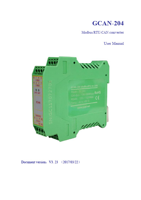
GCAN-204Modbus/RTU-CAN converterUser ManualDocument version:V3.23(2017/03/22)Contents1.Introduction (3)1.1Overview (3)1.2Properties at a glance (3)2.Installation (4)2.1Installation and fixation (4)2.2Connect to Serial bus (4)2.3Connect to CAN-Bus (5)3.Converter used (6)3.1The structure of CAN-Bus (6)3.2Termination resistor (7)3.3Indicator light (7)4.Configuration instructions (8)4.1Configuration to prepare (8)4.2Connect the software (8)4.3Configure parameter (9)4.4Configure mapping table (10)4.5Download parameters (11)4.6Save parameters (12)5.Examples (13)5.1Receive CAN data (13)5.2Transmit CAN data (13)6.Technical Specifications (14)1.Introduction1.1OverviewGCAN-204converter has one CAN-Bus interface,one serial interface.TheGCAN-204integrates the Modbus RTU protocol.With the GCAN-204,user can use the serial bus connect to other equipment(with Modbus RTU protocol)access the CAN-Bus communication interface.GCAN-204has integrated isolation protection ing DIN railway fixed,it can be easier to integrate into the control cabinet.1.2Properties at a glance●Modbus slave support function code:03H,04H,06H,16H●Serial baud rate:600bps~115200bps●CAN-Bus supports CAN2.0A and CAN2.0B frame format,conform to ISO/DIS11898standards●CAN baud rates:5Kbps~1Mbps●CAN-Bus isolation module insulation voltage:DC1500V●Power supply:9~30V(20mA,24V DC)●Interface using terminal blocks●Installation method:DIN rail●Working temperature range from-40to85°C●Size:(L)113mm*(W)100mm*(H)21mm2.Installation2.1Installation and fixationGCAN-204can be installed on a DIN rail,as shown in figure2.1.Figure2.1GCAN-204module installationNote:DIN rails require to connect with ground wire.GCAN-204power interface definition,as shown in table2.1.DC24V explanation1+24V DC+2-0V3NC NC4PE shieldTable2.1Power interface definition2.2Connect to Serial busGCAN-204serial interface use RS485interface.The pin definitions are shown in table2.2.Pin Port Name FeaturesC-BUS1RS485B-485B(-)signal lineC-BUS4A+485A(+)signal lineTable2.2RS485interface definitions2.3Connect to CAN-BusThe pin definitions for the CAN side of GCAN-204are shown in table2.3.Pin Port Name FeaturesGCAN CAN-G CAN_GNDL CAN-L CAN_L signal lineH CAN-H CAN_H signal lineTable2.3CAN-Bus signal assignment for GCAN-204Only CAN_H and CAN_H connect with each other,then CAN_L and CAN_L connect with each other.Then we establish a connection.3.Converter usedThe working principle of GCAN-204,as shown in figure3.1.Figure3.1Working principle of GCAN-204 3.1The structure of CAN-BusCAN-Bus connection,as shown in figure3.2.Figure3.2Topology structure of CAN-Bus3.2Termination resistorCAN-Bus requires two120Ωtermination resistors in the furthest of the two terminals, as shown in figure3.3.Figure3.3GCAN-204connection to other CAN converterPlease note:You should connect the two ends of the resistor to CAN_L and CAN_H respectively.3.3Indicator lightGCAN-204converter has one SYS indicator,one DAT indicator that can indicate the converter status.More functions are shown in table3.2.Indicator light Status Indicates the statusSYS Blinking Converter initialization,standbystatusOFF UninitializedDATBlinking Data transmissionOFF No data transmission Table3.2Status of the GCAN-204indicator4.Configuration instructions4.1Configuration to prepareOpen the shell of the converter,find the DIP switch shown below,turn switch2to "ON",then connected to the power supply,you can enter the configuration mode. Please note:GCAN-204uses RS485interface to configure,do not connect the "Mini USB"interface.4.2Connect the softwareWhen GCAN-204enters the configuration mode,use a RS485line to connects to PC. Open the"ModbusRTU CAN Config"software,then configure the parameters.The software interface is shown in figure4.1.Figure4.1ModbusRTU CAN Config software initial interfaceSelect the serial number,click"Connect".After setting up the connection,click"读参数Upload"to read the current configuration parameters,as shown in figure4.2. Please note:At this point the converter has been connected with the PC,please do not click"Connect"repeatedly.Figure4.2"ModbusRTU CAN Config"software main interface 4.3Configure parameterClick on"Communication Set".Figure4.3Configure the GCAN-204basic operating parameters In this interface,you can set:Node ID:The ID of the Modbus nodeParity:Odd parity or even parityByte Size:The length of the dataStop Bits:Stop the number of bitsRS232/485Baud:Modbus RTU baud rateCAN Baudrate:CAN-Bus baud rateFactory setting:Modbus RTU side baud rate is57600bps,CAN baud rate is250Kbps.4.4Configure mapping tablePress"Add"to add data."Receive CAN"Modbus address:0x00-0x7F,Modbus address of Transmit CAN:0x100-0x17F.4.4.1Receive CANClick"Receive CAN",as shown in figure4.4COB-ID:Sets the frame ID of the CAN-BusFrame Format:Sets the frame format(Standard/Extended)Frame Type:Sets the frame type(Data/RTR)Modbus Address:Modbus register first address settingLength:CAN frame data length,the maximum value of8Figure4.4Receive CAN mapping settings4.4.2Transmit CANClick"Transmit CAN"to add data mapping group,as shown in figure4.5.COB-ID:Sets the frame ID to be forwarded to CAN-Bus dataFrame Format:Sets the frame format(Standard/Extended)Frame Type:Sets the frame type(Data/RTR)Modbus Address:Sets the Modbus terminal register’s first addressLength:CAN frame data length,the maximum value is8. Set"Trace"or"Timer".Trace:When a Modbus master sends a Modbus address data with a06instruction,if the data changes,it will trigger the corresponding CAN data transmission. Timer:You can set the interval time,send CAN data circularly.It sets the interval in the"Send Timer",and enter the decimal number.The unit is milliseconds.For example,“enter1000”can sent at intervals of1000ms.4.5Download parametersAfter the configuration is completed,click on"设置参数Download",download the configuration data to the converter's"FLASH".If the download actions is unsuccessful,please download it again.Please note:After the data is downloaded successfully,you need to set the No.2 DIP switch to"OFF",and then restart the converter,to enable the new configuration.Figure4.5Transmit CAN mapping settings4.6Save parametersSave the configuration,click"保存文件SaveAs"to save the parameters to the PC. Then the file can be used many times.5.ExamplesThe user can use the included serial debugging assistant to send Modbus instruction debugging.Please note:choose"hexadecimal display"and"hexadecimal send"when using the serial debugging assistant.5.1Receive CAN dataFor example,configure the Modbus slave address:1,Modbus register first address: 0x01,CAN:standard frame,frame ID:0x181,CAN frame data:0x01,0x02,0x03,0x04,0x05,0x06,0x07,0x08.User Modbus master sends request frame:01030001000415C9GCAN-204response frame:010308020104030605080717C1Please note that the CRC is calculated by the CRC16checksum calculator.(With disk)At this point,the GCAN-204module has received a data frame with a frame ID of0x181from the CAN terminal of other equipment.5.2Transmit CAN dataFor example,Modbus slave address:1,Modbus register first address:0x101(decimal: 257),function code:16(10H),CAN:standard frame,frame ID:0x201,CAN frame data:0x01,0x02,0x03,0x04,0x05,0x06,0x07,0x08.User Modbus master sends request frame: 011001010004080201040306050807CB2EGCAN-204response frame:01100101000491F6Please note that the CRC is calculated by the CRC16checksum calculator.At this point,the CAN terminal of other equipment has received a data frame with a frame ID of0x201from the Modbus side of the GCAN-204module.6.Technical SpecificationsConnectionSerial interface Terminal blocksCAN interface Terminal blocksInterface characteristicsSerial interface Standard RS485interfaceSerial port baud rate600bps~115200bpsCAN interface ISO11898standard,CAN2.0A/BCAN baud rate1000K、500K、250K、200K、125K、100K、50K、20KElectrical isolation1500V,DC-DCCAN termination resistor None.You can add it between CAN_H and CAN_L if you need it.Power supplyPower supply voltage+9~30V DCPower supply current Maximum20mA(24V DC) Environmental testingWorking temperature-40℃~+85℃Working humidity15%~90%RH,no condensationEMC test EN55024:2011-09EN55022:2011-12 Protection grade IP20The basic informationOutline size113mm*100mm*21mmWeight120g。
- 1、下载文档前请自行甄别文档内容的完整性,平台不提供额外的编辑、内容补充、找答案等附加服务。
- 2、"仅部分预览"的文档,不可在线预览部分如存在完整性等问题,可反馈申请退款(可完整预览的文档不适用该条件!)。
- 3、如文档侵犯您的权益,请联系客服反馈,我们会尽快为您处理(人工客服工作时间:9:00-18:30)。
GCAN-203工业级智能蓝牙-CAN转换器用户手册文档版本:V3.25(2018/07/18)修订历史版本日期原因V1.002013/06/16创建文档V2.012013/12/20修正设备工作参数V3.012014/10/22添加部分参数V3.202016/09/09添加部分参数V3.252018/07/18调整文档结构目录1.功能简介 (4)1.1功能概述 (4)1.2性能特点 (4)1.3典型应用 (4)2.设备安装 (5)2.1设备尺寸 (5)2.2接口定义及功能 (5)3.设备使用 (7)3.1蓝牙连接 (7)3.2与CAN-bus连接 (7)3.3CAN总线终端电阻 (8)3.4系统状态指示灯 (8)4.CANBlueConfig配置软件使用 (10)4.1配置准备 (10)4.2软件连接 (10)4.3CAN接口参数设置 (11)4.4蓝牙参数设置 (13)4.5配置完成 (13)4.6保存配置文件 (14)4.7打开配置文件 (14)5.快速入门及应用举例 (15)5.1设备接线 (15)5.2蓝牙串口助手使用 (16)6.二次开发 (19)7.使用注意 (20)8.技术规格 (21)附录A:CAN2.0B协议帧格式 (22)附录B:GCAN-203数据流定义 (24)1.功能简介1.1功能概述GCAN-203(CANBlue)是集成1路标准CAN-Bus接口,使用蓝牙将CAN 总线数据发送给终端的工业级CAN-Bus通讯转换器。
采用GCAN-203模块,用户可以使用手持移动终端(手机/PAD)访问CAN节点,读取CAN总线数据。
这对于一些不易物理连接的CAN网络,使用GCAN-203模块通过无线终端与CAN网络连接进行数据交换将变得极为方便。
该模块已被广泛应用于构建现场总线实验室、工业控制、智能小区、汽车电子网络等CAN-Bus网络领域中数据处理、数据采集的CAN-Bus网络控制节点。
GCAN-203智能协议转换器是工业总线改造、无线采集CAN数据的关键性工具,同时该模块具有体积小巧、即插即用等特点,且用户可以使用标准DIN 导轨将模块固定安装,使其极易集成到现有的系统中。
GCAN-203智能协议转换器适合CAN-Bus低速数据传输应用,最高传输速率为300帧/秒。
同样GCAN-203智能协议转换器不仅适应基本CAN总线产品,也满足基于高层协议如DeviceNet、CANopen等CAN-Bus总线产品的开发。
1.2性能特点●CAN-Bus支持CAN2.0A和CAN2.0B帧格式,符合ISO/DIS11898规范;●CAN-Bus通讯波特率在5Kbps~1Mbps之间任意可编程;●CAN-Bus接口采用电气隔离,隔离模块绝缘电压:DC1500V;●最高数据流量:300帧/秒;●蓝牙使用2.0;●使用9~24V DC供电;●供电电流:30mA24V DC;●使用CANBlue Config配置工作模式及参数;●可用配套卡轨连接件,安装到DIN卡轨上;●工作温度范围:-40℃~+85℃;1.3典型应用●不易物理连接的CAN系统访问;●工业现场网络数据监控;●CAN教学应用远程通讯;●CAN工业自动化控制系统;●低速CAN网络数据采集数据分析;●智能楼宇控制数据广播系统等CAN-Bus应用系统。
2.设备安装2.1设备尺寸设备外形尺寸:(长,含接线端子)110mm*(宽)70mm*(高)24mm,其示意图如图2.1所示。
图2.1GCAN-203外形尺寸2.2接口定义及功能GCAN-203集成1路1路USB接口、一路DC9-24V电源接口及1路CAN-bus接口。
GCAN-203USB接口位置及定义如图2.2、表2.1所示。
图2.2USB接口位置引脚端口名称功能1USB USB与电脑连接配置参数表2.1USB接口定义GCAN-202模块电源接口及CAN-bus 接口由插拔式接线端子引出,可以用于连接1个CAN-bus 网络或者CAN-bus 接口的设备。
电源及CAN-bus 接口位置及定义如图2.3、表2.2所示。
图2.3GCAN-203模块接口位置引脚(由左至右)端口名称功能1DC 9-24VDC 9-24V 9-24V 直流电源输入正2GND 9-24V 直流电源输入负3NC 无连接4CAN CAN-L CAN_L 信号线(CAN 低)5CAN-G CAN 地6CAN-HCAN_H 信号线(CAN 高)表2.2GCAN-203模块的CAN-bus 信号分配3.设备使用设备使用前需根据用户具体实际情况对GCAN-203模块进行工作参数配置,使用CANBlue Config软件可对该模块配置的参数包括:CAN总线波特率、CAN 总线工作模式、GCAN-203蓝牙名称、GCAN-203连接密码等。
GCAN-203设备出厂默认CAN总线波特率为250K,工作模式为正常模式,蓝牙名称为设备背面的SN编号,连接密码1234。
3.1蓝牙连接用户需安装“③安卓系统串口助手安装包”中的“CANBlue.RSO.apk”软件,搜索蓝牙设备,并输入连接密码,即可与GCAN-203模块建立连接(默认设备名称:GCAN-203设备的SN号码,默认连接密码:1234),通过蓝牙串口助手软件即可对CAN总线数据进行收发。
详细的图文说明可参考本手册 5.快速入门及应用举例。
3.2与CAN-bus连接GCAN-203模块接入CAN总线连接方式为将CAN_H连CAN_H,CAN_L连CAN_L即可建立通信。
CAN-Bus网络采用直线拓扑结构,总线最远的2个终端需要安装120Ω的终端电阻;如果节点数目大于2,中间节点不需要安装120Ω的终端电阻。
对于分支连接,其长度不应超过3米。
CAN-Bus总线的连接见图3.1所示。
图3.1CAN-Bus网络的拓扑结构注意:CAN-Bus电缆可以使用普通双绞线、屏蔽双绞线。
理论最大通信距离主要取决于总线波特率,最大总线长度和波特率关系详见表3.1。
若通讯距离超过1Km,应保证线的截面积大于Φ1.0mm2,具体规格应根据距离而定,常规是随距离的加长而适当加大。
波特率总线长度1Mbit/s40m500kbit/s110m250kbit/s240m125kbit/s500m50kbit/s 1.3km20kbit/s 3.3km10kbit/s 6.6km5kbit/s13km表3.1波特率与最大总线长度参照表3.3CAN总线终端电阻为了增强CAN通讯的可靠性,消除CAN总线终端信号反射干扰,CAN总线网络最远的两个端点通常要加入终端匹配电阻,如图3.2所示。
终端匹配电阻的值由传输电缆的特性阻抗所决定。
例如双绞线的特性阻抗为120Ω,则总线上的两个端点也应集成120Ω终端电阻。
如果网络上其他节点使用不同的收发器,则终端电阻须另外计算。
图3.2GCAN-203与其他CAN节点设备连接请注意:GCAN-203模块内部未集成120Ω终端电阻。
如需连接时,请将120Ω电阻并联接入CAN_H与CAN_L接口。
3.4系统状态指示灯GCAN-203模块具有1个PWR指示灯、1个SYS指示灯、1个CAN指示灯来指示设备的运行状态。
这3个指示灯的具体指示功能见表3.2,这3个指示灯处于不同状态下时,设备状态如表3.3所示。
指示灯颜色指示状态PWR绿电源指示SYS绿蓝牙终端设备连接指示CAN红/绿CAN接口状态指示GCAN-203模块上电后,PWR点亮,表明设备已经供电,系统正在初始化;否则,表示存在系统电源故障。
供电正常且初始化通过后,SYS指示灯会快闪表示没有终端设备连接到GCAN-203模块,当有终端连接成功后,指示灯将变为慢闪。
CAN指示灯有两种颜色,如果CAN数据通信正常,指示灯绿色闪烁;如果通信错误,则红色灯闪烁。
指示灯状态指示状态PWR亮电源供电正常不亮电源供电故障SYS快闪无终端与GCAN-203连接慢闪终端与GCAN-203连接成功CAN红色闪烁CAN总线通信错误绿色闪烁CAN总线通信正常4.CANBlueConfig配置软件使用4.1配置准备断开GCAN-203供电电源,用USB线连接GCAN-203与电脑即可,GCAN-203进行配置时,无需再外接电源。
4.2软件连接当GCAN-203模块与电脑正常连接后,打开光盘中“②CANBlue模块配置软件”中的“CANBlueConfig”软件对模块进行配置。
图4.1GCAN-203Config软件主界面软件上面有5个工具按钮:Connect——连接设备;Upload——将设备中的配置信息读出来;Download——将配置信息下载到设备的Flash中;Open——打开读取PC中的配置信息文件;SaveAs——将配置信息文件保存到电脑中。
配置前请将USB方口线一端连接到电脑,另一端连接到GCAN-203设备上。
待设备的PWR灯点亮的时候,点击“Connect”连接设备,连接成功后如图4.1所示。
请注意,配置的时候不需要外接9-30V电源。
连接成功后软件界面左面的栏中会显示连接设备的设置列表,这时可以点击“UpLoad”将设备中的参数上载到电脑。
图4.2GCAN-203Config软件上载参数4.3CAN接口参数设置点击“CAN Param”一行进入CAN总线通信参数设置。
点击“CAN Baud”参数对应波特率参数对应波特率01000K1800K2666K3500K4400K5250K6200K7125K8100K980K1050K1140K1220K1310K145K图4.3CAN波特率设置“CAN Mode”及“CAN Filter”为可定制功能选项,暂不开放。
默认均设置为0即可。
图4.4CAN工作模式设置4.4蓝牙参数设置点击“BlueTooth Param”一行进入蓝牙通信参数设置。
图4.5蓝牙参数设置在此页面中,用户可以根据自己的喜好设置蓝牙设备名称和连接密码。
(设备名称默认为GCAN-203设备的SN号码,密码为1234)4.5配置完成当用户对GCAN-203模块配置完成后,可以点击“Download”将配置数据写入到设备的FLASH中,如图4.6所示。
图4.6下载参数到GCAN-203模块写入成功后会提示“download Param success”,关闭软件后对模块进行重新上电,新的配置即可生效。
请注意:配置完成后必须对设备重新上电,否则配置将不能生效。
4.6保存配置文件设置完成的配置参数和从设备中Upload上来的配置参数都可以保存到PC 机中,点击工具栏中的SaveAs根据提示设置保存文件名称,就可以将配置参数保存到PC中。
配置文件可以再次打开使用。
4.7打开配置文件可以使用OPEN功能,打开以前保存的配置文件,然后进行修改。
