SKD32.82.62.62 电动液压阀门执行器说明书_英文版
电动阀门执行器出口英文使用说明书
Non-Invasive Electric Actuator Electronic control module debugginginstructionsVersion V201SummaryThis component can receive the DCS system on-off signals (passive dry contact of active, active 24 v, 220 v, keep running can switch) or analog signals (DC4-20 ma, 0 to 10 v, etc.), direct drive electric actuators switch action or adjust the action. Output DC4-20 ma feedback current and contact/remote control state instructions. The component integration the servo control unit, solid-state drive unit, liquid crystal display unit, knobs and other ancillary units and aluminum shell assembly operation.The product operates as a fool camera is simple, like intelligent perfect protection function.2Operating Instructions2.1Knob Operating InstructionsThe red knob is the mode button, can be switched between Local/Stop/Remote. Or in a set state, to save the menu contents (from the stop bit screwed to the site) or to exit the menu(from the stop bit screwed into the remote).Black knob for the operating button can be opened or closed operation at the local.Or to plus or minus in the set state.With button operation, short time effect for the inching mode. When the operation button is effective for more than 3 seconds, in the lower right corner of the LCD, the bc is displayed automatically entered into the hold mode. When actuator movement, click the action button reverse rotation or spin mode button to Stop, the actuator Array stops.2.2 setting tool description (setting tool are optional, needto please when ordering special instructions)"Up" button = Open calibration key, "Down" button = close calibrationkey, "Enter" button = Confirm key or Save key"Stop" button = stop key, "Open" button = open key, "Close" button =close key.When mode button at Local location, press "Open" button to performopen, press "Close" button to perform off. In the action, press the"Stop" button to stop the move, short press "Close" to stop the openingprocess, short press "Open" to stop the closing process.In local mode, even by three "Up" key to enter the open position calibration status, "Open", "Close" and "Stop" keys to control the electric actuator to open, close and stop, "Enter" key to save the trip, "Stop "key is used to return.In local mode, even by three "Down" key to enter the closed position calibration status, like the rest of the operation as above.3Signal query (LCD lower left corner for a signal check area) 3.1 Remote control signal inquiryWhen the mode button is screwed into the Remote, the remote control signal received is displayed in the lower-left corner of the LCD. Switch type: show OP represents a open signal, show CL represents a close signal, show BC represents a keep signal (multi state of coexistence of alternate display). Regulating type: to display the received control current value or voltage value.3.2 Valve position signal queryWhen the mode button is screwed onto the Local, the LCD shows the valve position signal in lower left corner. When using a potentiometer, show the percentage of resistance (d01 ~ d99); When using 12 encoder, shows the percentage of the encoder (b01 ~ b99); When using 18 encoder, display micrometer ratio of the encoder (001 to 999).4 4 Stroke calibrations4.1 Calibration for close limit:The mode button at the Stop position, the rotary operation knob to the Close position for about 3 seconds, until the letter L is flashing of the LCD to release operation button, then the mode button to the Local position, now letter L no longer flashes and the system into the closed position calibration status. The actuator can open or close by the operating button. When the actuator operates to the closed position, then the mode button to spin the Stop position, and back to the Local position, at this time the red LED flashing two times said the closed position calibration is completed. If the mode button is screwed to the Remote position from Stop position, that exit travel calibration.4.2 Calibration for open limitThe mode button at the Stop position, the rotary operation knob to the Open position for about 3 seconds, until the letter H is flashing of the LCD to release operation button, then the mode button to the Local position, now letter H no longer flashes and the system into the open position calibration status. The actuator can open or close by the operatingmode button to spin the Stop position, and back to the Local position, at this time the green LED flashing two times said the open limit position calibration is completed. If the mode button is screwed to the Remote position from Stop position, that exit travel calibration.Note: When you save a stroke, display Fu or Fn characters on the LCD, please re-adjust potentiometer or rotary encoder range, and recalibrate the trip.5Feedback current trimming5.1 Feedback current 4mA trimmingThe mode button at the Stop position, the rotary operation knob to the Open position for about 10 seconds, until the letter LF is flashing of the LCD to release operation button, then the mode button to the Local position and back to the Stop position, and the system into the 4mA current trimming status. At this point,the size of the output current can be adjusted by the operating button. When adjusting the output current reaches 4mA, then mode button to spin the Local position, this time the red LED flashes three times, said 4mA output current trim is complete. If the mode button to Stop position from Remote position, which exit status of the output current trim.5.2 Feedback current 20mA trimmingThe mode button at the Stop position, the rotary operation knob to the Open position for about 10 seconds, until the letter HF is flashing of the LCD to release operation button, then the mode button to the Local position and back to the Stop position, and the system into the 20mA current trimming status. At this point,the size of the output current can be adjusted by the operating button. When adjusting the output current reaches 4mA, then mode button to spin the Local position, this time the green LED flashes three times, said 20mA output current trim is complete. If the mode button to Stop position from Remote position, which exit status of the output current trim.6About dead zoneThe dead zone to adapt automatically, without setting can ensure that in any conditions without oscillation, and the positioning precision is higher.7Alarm description (error code displayed on the LCD in the lower right corner) FaultcodeFault informationFA Actuator running direction errorFu V alve position potentiometer or encoder Angle is too largeFn V alve position potentiometer or encoder Angle is too smallFP Power phaseFF Broken valve position potentiometer, rotary to blind or pick the wrong line, or encoder failure.FC Over closed torqueFO Over open torqueFH Remote control signals to open and close signals exist (only on-off type)FS Control current signal is lost (only positioning)Fb Current control signal calibration error(only positioning)Fd Stall or other causes the valve position does not changeFL Limit contact line or torque contact line reversedFE The motor is too hot or the torque public terminal is openNOTE: The green LED is the open limit position light on the screen, the red LED is closed position light on the screen.8Advanced SettingsNOTE: All the Advanced Settings can be set after the mode button in the "Local" position. Advanced settings must open the electrical box cover and you can operate. The Close Key and Open Key mentioned below are in the electronic control board.8.1 Action when the control current loss:(Only positioning type, default: Remain in Situ)8.1.1 To press the “Close Key” and power up for 3 seconds until the red LED on the board is lit. And you release the key, then the red LED flashes three times; the “FullClose” setup is completed.8.1.2 To press the “Open Key” and power up for 3 seconds until the green LED on the board is lit. And you release the key, then the green LED flashes three times; the “Full Open” setup is completed.8.1.3 Simultaneously press two keys and power up for 3 seconds until the green and red LEDs on the board are lit. And you release the two keys simultaneously, then the two LEDs flashes three times; the “Remain in Situ” setup is completed.8.2 Control current calibration:(Only positioning type)8.2.1 To send 4mA control current to the module from the outside, press the “Close Key” and power up for 10 seconds until the red LED on the board is lighted second times. And you release the key, then the red LED flashes three times; and the4mA calibration is completed.8.2.2 To send 20mA control current to the module from the outside, press the “Open Key” and power up for 10 seconds until the green LED on the board is lighted second times. And you release the key, then the green LED flashes three times; and the20mA calibration is completed.8.3 Polarity for the control current:(Only positioning type)20mA = Full Open /4mA = Full Open (default:20mA = Full Open) Simultaneously press “Open Key” and “Close Key” and then power up for 10 seconds. To release the key after the red LED and green LED second lights up. Short press “Open Key” or “Close Key” to alternately lit red LED or green LED. The red LED light represents “20mA = Full Open”, the green LED light represents “4mA = Full Open”. Simultaneously press “Open Key” and “Close Key” for 3 seconds. To release two keys after the two LEDs lights up. Then corresponding LED flashes three times, the polarity for the control current setup is complete.8.4 Two-Wire Control:(Only on-off type)Disable or Open First or Close First (default: Disable)8.4.1Close FirstYou press “Close Key” and then power up for 10 seconds. The key is released after the red LED second light up. And the red LED flashes three times, this setup is complete. This Close First refers to the actuator close operation when voltages signal on the “Remote Close” terminal of the actuator. But no voltage signal, actuators open operation. When wiring, “Remote Open” terminal connected to 24V +.8.4.2Open FirstYou press the “Open Key” and then power up for 10 seconds. The key is released after the green LED second light up. And the green LED flashes three times, this setup is complete.This Open First refers to the actuator open operation when voltages signal on the “Remote Open” terminal of the actuator. But no voltage signal, actuators close operation. When wiring, “Remote Close” terminal connected to 24V +.8.4.3 DisableYou press the two keys simultaneously and then power up for 10 seconds. The key is released after the two LEDs second lights up. Then the two LEDs flashes three times, this setup is complete.8.5 Close direction:Clockwise /Anti-clockwise (default:Clockwise)You press the “Open Key” and “Close Key” simultaneously and then power up for 20 seconds. The keys are released after the red LED and green LED third lights up. Short press “Open Key” or “Close Key” to alternately lit red LED or green LED. Red LED light represents “Clockwise”, green LED light represents “Anti-clockwise”. You press the two keys simultaneously for 3 seconds. The keys is released after the two LEDs light up. Then corresponding LED flashes three times, the Close direction setup is complete.9Common problems to deal withPower LED is not lit or digital display does not show 1. Power is not actually access. 2. voltage is too low 3. Wiring fault. 4. Module badLEDs and digital display abnormal 1. See fault code.2. Query information.3. Replace the moduleAfter power on ,actuator can be not control in the LOCAL and REMOTE mode 1. Wiring fault or loose wiring. 2. Fault Protection.3. Motor bad or stuck.4. Bad start capacitor.5. module badLOCAL mode work is normal but the REMOTE mode can't control 1. No signal or junction anti- , 2. Bad or no knob plate in Remote3. Positive / reaction set wrong.4. Module badREMOTE mode work is normal but the LOCAL mode can't control 1. Not in LOCAL mode. 2. Knobs board bad or not at the scene mode. 3. Operation button is not properly screwed in placeActuator can open but not close or can close but not open 1. Torque wiring fault or loose wiring. 2. to limit position or over torque3. Motor bad or stall or wiring fault.4. Module badThe action immediately after power on 1. Wiring fault. 2. control signal is present3. Implementation the action when the control current loss4. Set the wrong.5. module badThe middle position can move but to the limit position does not move 1. Reverse limit switch line. 2. Motor bad or loose wiring 3. Module badThe direction of movement is the anti 1. Motor lines reversed. 2. Anti valve calibration.3. Signal Reverse4. Polarity for the control current or closing direction set wrong.No output current or sometimes no 1. The output wiring fault or bad. 2. Module bad 3. potentiometer wiring fault or loose wiringFeedback current is larger or smaller or unchanged 1.Potentiometer failure. 2. Calibration error.3. module bad4. potentiometer meshing with drive gear not wellNote: Please strictly in accordance with the wiring diagram electrical wiring connection.Like has the change, without notice。
电动阀门电动驱动器说明书
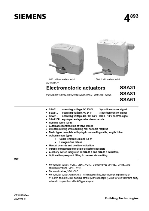
CE1N4893en 2020-05-11Building Technologies4893SSA.. without auxiliary switch SSA..1 with auxiliary switchACVATIX™Electromotoric actuatorsFor radiator valves, MiniCombiValves (MCV) and small valvesSSA31..SSA81..SSA61..·SSA31.. operating voltage AC 230 V 3-position control signal ·SSA81.. operating voltage AC 24 V 3-position control signal ·SSA61.. operating voltage AC / DC 24 V DC 0…10 V control signal ·SSA61EP.. equal-percentage valve characteristic ·Nominal force 100 N·Automatic identification of valve stroke·Direct mounting with coupling nut, no tools required·Basic types complete with plug-in connecting cable, length 1.5 m ·Optional cable types·Cable length 2.5 m and 4.5 m ·Halogen-free cables·Manual override and position indication·Parallel connection of multiple actuators possible·Auxiliary switch integrated in SSA31.1 and SSA81.1 actuators ·Optional tamper-proof fitting to prevent dismantlingUse·For radiator valves, VDN.., VEN.., VUN.., Combi valves VPP46.., VPI46.. and MiniCombiValves, VPD.., VPE..·For small valves, VD1..CLC· For radiator valves with M30 x 1.5 threaded fitting, nominal closing dimension11.6 mm and a 2.5 mm nominal stroke (without adapter). Also for use with third-party valves in conjunction with AV-type adapter2/10SiemensCE1N4893enSmart InfrastructureBuilding Technologies2020-05-11· For modulating or 3-position control in heating systems, chilled ceilings and terminal units.Type summaryTypereference Operating voltage Run time at 50 HzControl signalConnecting cableAuxiliary switchSSA31AC 230 V150 s3-position1.5 m SSA31/001)no cable SSA31.1 1.5 m YesSSA81AC 24 V1.5 m SSA81/001)no cable SSA81.1 1.5 m YesSSA61AC / DC 24 V 34 s DC 0...10 V1.5 m SSA61/001)no cable SSA61EP 2) 1.5 m SSA61EP/002)no cable1)For available cable lengths or terminal block connectors refer to "Accessories", page 42)With equal-percentage valve characteristicTypereference DescriptionOperating voltage Control signalASY3L25Connecting cable 2.5 mAC 230 V3-positionASY3L45Connecting cable 4.5 m ASY8L25Connecting cable 2.5 m AC 24 V ASY8L45Connecting cable 4.5 mASY8L45HF Connecting cable 4.5 m, halogen-free, VDE 0207-24ASY6L25Connecting cable 2.5 m AC / DC 24 V DC 0...10 V ASY6L45Connecting cable 4.5 m ASY6L45HF Connecting cable 4.5 m, halogen-free, VDE 0207-24ASY98Retaining screw for terminal block connectors. Included in ASY99 and ASY100.ASY99Terminal block connector for 3-position actuators SSA81../00ASY100Terminal block connector for DC 0…10 V modulating actuators SSA61/00AL40Tamper-proof fitting to prevent dismantling of actuators Adapter typefor third-party valves Adapter type for third-party valves AV51Beulco old (M30x1.0)AV56Giacomini AV522)Comap AV57Herz AV53Danfoss RA-N (RA2000)AV58Oventrop old (M30x1.0), till 2002AV54Danfoss RAVL AV592)Vaillant AV55Danfoss RAV AV60TA, till 20021)AV61Markaryd (MMA)1) No adapter required for type TBV-C 2)While stocks lastOrdering Type Stock no.DescriptionQuantity SSA81/00SSA81/00Electromotoric actuator 2ASY8L45ASY8L45Connecting cable2Actuators, valves and accessories are packed separately. Items are suppliedindividually packed.Overview tables, see page 9.AccessoriesExample:DeliveryRev.-No.3/10SiemensCE1N4893en Smart Infrastructure2020-05-11Equipment combinationsk vs = nominal flow rate of cold water (5...30 °C) through the fully open valve (H 100)at a differential pressure of 100 kPa (1 bar)V & = Nominal volume flow at 0.5 mm strokeTo ensure trouble-free operation of third-party valves with the SSA.. actuator, the valves must satisfy the following requirements:·Threaded connections with coupling nut M30 x 1.5·Nominal force F £ 100 N ·Dimension x x > 9.0 mm ·Dimension y y £ 14.5 mmFunction / mechanical designWhen the actuator is driven by DC 0…10 V control voltage or by a 3-position signal, it produces a stroke which is transmitted to the valve stem.The description of operation in this document applies to the valve versions which are fully open when de-energized (NO).·Voltage at Y1:Stem retracts Valve opens ·Voltage at Y2:Stem extends Valve closes ·No voltage at Y1 and Y2:Actuator maintains its current position· The valve opens / closes in proportion to the control signal at Y.· At DC 0 V, the valve is fully closed (A à AB).· When power supply is removed, the actuator maintains its current position.1)Actuator is calibrated to 2.5 mm stroke of VPI46.15.L06S t r o k e 2,5 m m ((c a l i b r a t e d )1)22.51.510.500246810control signal Y [V]Type reference Valve type k vs [m 3/h]V&[l/h]PN class Data sheet VDN.., VEN.., VUN..Radiator valves 0.09…1.41PN 10N2105, N2106VPD.., VPE..MCV radiator valves 25…483N2185VD1..CLC Small valves 0.25…2.60N2103VPP46.., bi valves 30…4001PN 25N4855For other radiator valves with type AV.. adapters refer to "Type summary / accessories"Radiator valves (M30 x 1.5) from other manufacturers, without adapter:· Heimeier · Crane D981..· TA-Type TBV-C · Oventrop M30 x 1.5 (from 2001)· MNG · Junkers · Honeywell-Braukmann · Cazzaniga · Beulco (new)Valves from othermanufacturers3-position control signalSSA31.. / SSA81..DC 0...10 V control signalSSA61, SSA61/004/10SiemensCE1N4893enSmart InfrastructureBuilding Technologies2020-05-11Combi valves VPI46../VPP46.. in combination with SSA61EP.. have an equal-percentage characteristics.· The valve opens / closes in equal percentage ratio to the control signal at Y.· At DC 0 V, the valve is fully closed (A à AB).· When power supply is removed, the actuator maintains its current position.1)Actuator is calibrated to 2.5 mm stroke of VPI46.15L06S t r o k e 2,5 m m (c a l i b r a t e d )1)2.42.51.510.500246810control signal Y [V]·Plastic housing·Locking-proof, maintenance-free gear train·Manual override with hexagonal socket wrench 3 mm ·Reduced power consumption in the holding positions·Load-dependent switch-off in the event of overload and in stroke end positions·Parallel operation of 6 SSA31.., 24 SSA81.. and 10 SSA61..possible, provided the controllers’ output is sufficient ·Terminal block connectors for customer made cables available (only for use with AC 24 V and AC / DC 24 V actuators)·Connecting cables with AC 24 V and AC 230 V connectors cannot be mixed up·Halogen-free cables availableAccessoriesAdapter types AV51 to AV61 are available for mounting the SSA.. actuators on third-party radiator valves as shown under "Type summary/accessories", page 2.1xtighten gentlyType ASY98 to secure the cable connector. Included in ASY99 and ASY100.The cable connector snaps into position,but can be additionally secured with the retaining screw.DC 0...10 V control signal SSA61EP,SSA61EP/00Features and advantagesAdapter type AV.. for third-party valves Tamper-proof fitting AL40Retaining screw ASY985/10SiemensCE1N4893en Smart Infrastructure2020-05-11For special cable lengths of the AC / DC 24 V actuators.·Type ASY99 for 3-position actuators SSA81../00·Type ASY100 for DC 0…10 V modulating actuators SSA61/00The terminal block connectors are supplied complete with mounting instructions (74 319 0385 0).Notes The actuators must be electrically connected in accordance with local regulations (refer to "Connection diagrams", page 9).Regulations and requirements to ensure the safety of people and property must be observed at all times!The permissible temperatures (refer to "Technical data", page 7) must be observed.The connecting cable of the actuator may come into contact with the hot valve body,provided the temperature of the valve body does not exceed 80 °C.Actuator types SSA 31.1 and SSA81.1 have a built-in auxiliary switch. The switch cannot be fitted in other actuators later.Mounting instructions (Ref. 74 319 0497 0) are enclosed in the product packaging.The actuator and valve are assembled with the coupling nut; no tools or adjustments are required.The actuator must be fitted in position 1 with the power disconnected (refer also to "Manual override", page 6):·Position the actuator and tighten the coupling nut manually ·Do not use any tools such as wrenches·Avoid lateral pressure or (cable) tension on the mounted actuator!In the case of actuators without a connecting cable (SSA../00), the separately orderedCrimp ferrule on stripped wire of connecting cable.When commissioning, check the wiring and the functioning of the actuator and auxiliary switch, if fitted.·Actuator stem extends (from position 1 to 0): Valve closes ·Actuator stem retracts (from position 0 to 1): Valve opens During commissioning and whenever the operating voltage is switched on,the SSA61.. runs a self-calibration routine. (Valve stroke 0® Max.stroke ® Setpoint).Never intervene manually in this process.ON0 %EngineeringMountingOrientationInstallationCommissioningTerminal block connectors ASY99ASY1006/10SiemensCE1N4893enSmart InfrastructureBuilding Technologies2020-05-11The second or third attempt at calibration occurs automatically after an 8-minute delay.After three failed calibration attempts the actuator stem remains in the extended position and the radiator valves are closed.For valves with strokes < 1.5 mm, the actuator/valve combination locks after three failed calibration attempts.The new Siemens type VDN.., VEN.. and VUN.. radiator valves have in all 1.5 mm stroke.A 3 mm hexagonal socket wrench can be used to move the actuator to any position.However, if a control signal from the controller is present, then this takes priority in determining the position.To retain the manually set position, unplug the connecting cable or switch off the operating voltage and the control signal.2.5 mm stroke5.5 mm strokeThe actuators are maintenance-free.When carrying out service work on the plant, following must be noted:·Turn power off (e.g. remove the plug)·If necessary, disconnect electrical connections from the terminals·The actuator must be commissioned only with a correctly mounted valve in place!SSA.. actuators cannot be repaired; the complete unit must be replaced.DisposalWarrantyThe technical data given for these applications is valid only when the actuators are used with the Siemens valves listed under "Equipment combinations", page 2.The use of the SSA.. actuators in conjunction with third-party valves invalidates any warranty offered by Siemens Building Technologies / HVAC Products.Note: Correctcalibration is only possible ·with valve·stroke > 1.5 mmOperationNoteManual overrideMaintenance!Repair7/10SiemensCE1N4893en Smart Infrastructure2020-05-11Technical dataPower supplyControlFunctional dataElectrical connectionsNorms and directivesDimensions /weight Housing colors 1)Provided the controller output is sufficient2)The documents can be downloaded from /bt/download8/10SiemensCE1N4893enSmart InfrastructureBuilding Technologies2020-05-11General ambient conditionsOperation EN 60721-3-3Transport EN 60721-3-2Storage EN 60721-3-1Environmental conditions Class 3K3Class 2K3Class 1K3Temperature +1...+50 °C –25...+70 °C –5...+50 °C Humidity 5...85 % r.h.< 95 % r.h. 5...95 % r.h.Connecting cableConnection terminalsY2Y1G4864Z 15Control signal CLOSE Control signal OPENSystem potential AC 24 VG0Y G4864Z 16System neutralControl signal DC 0...10 V System potential AC/DC 24 VFactory setting: 50 %0...50 % Q11® Q1250...100 % Q11® Q14The switching point can be adjusted by turning the switching cam with a screwdriver (see Mounting Instructions).Recommended connecting cable: H03VV-F, 2x0.5…0.75 mm 2.ASY3L.. with SSA31..ASY8L.. with SSA81..ASY6L.. with SSA61..ASY99for SSA81..ASY100for SSA61..Terminals for auxiliary switchesSSA31.1, SSA81.19/10SiemensCE1N4893en Smart Infrastructure2020-05-11Connection diagramsN Controller Y ActuatorL System potential AC 230 V NSystem neutralY1, Y2Control signal OPEN, CLOSE Q1, Q2Controller contactsN Controller YActuatorSP, G System potential AC 24 V SN, G0System neutralY1, Y2Control signal OPEN, CLOSE Q1, Q2 Controller contactsN Controller YActuatorSP, G System potential AC 24 V SN, G0System neutral Y Control signalSSA31..SSA81..SSA61..10/10SiemensCE1N4893enSmart InfrastructureBuilding Technologies2020-05-11DimensionsDimensions in mm8377484893M 0172.59M30 x 1,54893M 0298.5834889.5M30 x 1,59Revision numbersType reference Valid from Rev.-No.Type reference Valid from Rev.-No.SSA31K SSA61K SSA31/00K SSA61/00KSSA31.1K SSA81K SSA81/00K SSA81.1KActuator without auxiliary switch SSA31..SSA81..SSA61..Actuator with auxiliary switch SSA31.1..SSA81.1..Issued bySiemens Switzerland LtdBuilding Technologies Division International Headquarters Theilerstrasse 1a 6301 Zug SwitzerlandTel. +41 41-724 24 24/buildingtechnologies © Siemens Switzerland Ltd, 2005Technical specifications and availability subject to change without notice.。
SKD…U电子阀门驱动器安装说明说明书
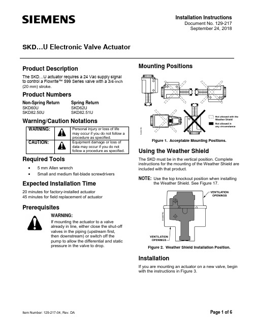
Installation InstructionsDocument No. 129-217 September 24, 2018SKD …U Electronic Valve ActuatorItem Number: 129-217-04, Rev. DAPage 1 of 6Product DescriptionThe SKD…U actuator requires a 24 Vac supply signal to control a Flowrite™ 599 Series valve with a 3/4-inch (20 mm) stroke.Product NumbersNon-Spring Return Spring Return SKD60U SKD62U SKD82.50USKD82.51UWarning/Caution NotationsWARNING:Personal injury or loss of life may occur if you do not follow a procedure as specified.CAUTION:Equipment damage or loss of data may occur if you do not follow a procedure as specified.Required Tools• 5 mm Allen wrench•Small and medium flat-blade screwdriversExpected Installation Time20 minutes for factory-installed actuator 45 minutes for field replacement of actuatorPrerequisitesWARNING:If mounting the actuator to a valvealready in line, either close the shut-off valves in the piping (upstream first, then downstream) or switch off the pump to allow the differential and static pressure in the valve to drop.Mounting PositionsFigure 1. Acceptable Mounting Positions.Using the Weather ShieldThe SKD must be in the vertical position. Complete instructions for the mounting of the Weather Shield are included with that product.NOTE: Use the top knockout position when installingthe Weather Shield. See Figure 17.Figure 2. Weather Shield Installation Position.InstallationIf you are mounting an actuator on a new valve, begin with the instructions in Figure 3.Document No. 129-217 Installation Instructions September 24, 2018Page 2 of 6 Siemens Industry, Inc.Removing the Actuator from the Valve1. Remove the actuator cover.2. Disconnect the wires and conduit, if installed.3. Loosen the valve stem retainer using a 5 mm Allenwrench and lower the valve stem into the valve. 4. Loosen the yoke nuts using a 5 mm Allen wrenchin the actuator yoke.5. Remove the actuator from the valve, being carefulnot to damage the valve stem.Continue with Mounting an Actuator to a Valve .Figure 3. Preparing a new Valve.Mounting an Actuator to a Valve.NOTE: Install the stem heating element,(P/N ASZ6.6), if used, before proceeding.Figure 4.NOTE: Ensure the yoke nuts are loose enough toallow the actuator to slip over the bonnet. See Figure 5.Figure 5.Figure 6.NOTE: Hold the stem retainer in place as you tightenit around the valve stem. See Figure 6.Figure 7.NOTE: Position the actuator to accommodate thewiring. Hold the actuator in place while tightening the yoke nuts. See Figure 7.Figure 8.1234 567Document Number: 129-217Installation Instructions September 24, 2018Siemens Industry, Inc. Page 3 of 6WiringCAUTION:Use care when removing the knockout. Do not damage the circuit board.Do not use autotransformers. Use earth ground isolating step-down Class 2 transformers.Determine supply transformer rating by summing total VA of all actuators used. The maximum rating for a Class 2 power supply circuit is 100 VA.ActuatorPower ConsumptionActuators Per Class 2 Supply Circuit* (80% of Transformer VA)S KD6…U 17 VA 4 SKD82.50U 13 VA 8 SKD82.51U18 VA5* Operating more actuators requires additional transformers or separate 100 VA power supplies.Wiring DiagramsSKD60U/SKD62U Figures 9 and 10 SKD82.50U/51UFigures 11 through 13SKD6…U12Figure 9. SKD6…U. DIP Switches1Selection of Control Signal 2Selection of Flow Characteristic ON 4 to 20 mAModified*OFF(Factory Setting)0 to 10 Vdc Default*Changing the default setting will modify an equalpercentage valve to a linear flow characteristic. When set to default, the flow characteristic is determined by the valve body.Figure 10.Connecting Terminals24 VacG System Potential (SP) G0 System Neutral (SN)Y Control Input: 0 to 10 Vdc or 4 to 20 mA(DIP switch selectable) Z Override Control(See Technical Instructions 155-180P25) M Measuring NeutralU Output for 0 to 10 Vdc or 4 to 20 mAmeasuring voltage. It will match the input signal type. The position output signal U will switch from 0 to 10 Vdc to 4 to 20 mA when a 4 to 20 mA input signal is selected and used on the terminal.Wiring for SKD82…UFigure 11. Location of Terminals.Document No. 129-217 Installation Instructions September 24, 2018Page 4 of 6 Siemens Industry, Inc.Wiring for SKD82…U , ContinuedFigure 12. Non-Spring Return SKD82.50U.Connecting Terminals G System Potential 24 Vac (+)Y1 Outward movement of coupling piece (0 to 1) Y2 Inward movement of coupling piece (1 to 0) Cm1 Limit switch for 100% strokec1 ASC9.3DU double auxiliary switch c2ASC9.3DU double auxiliary switch 1000 ΩASZ7.3 potentiometerThe diagram shows all possible connections. How many and which are used depend on the application.Figure 13. Spring Return SKD82.51U.Connecting TerminalsG System Potential 24 Vac (+) 21 System Neutral (SN) Y1 Outward movement of coupling piece (0 to 1) Y2 Inward movement of coupling piece (1 to 0) Cm1 Limit switch for 100% stroke c1 ASC9.3DU double auxiliary switch c2 ASC9.3DU double auxiliary switch 1000 Ω ASZ7.3 potentiometermany and which are used depend on the application.Start-UpCheck the wiring for proper connections.Consult Flowrite 599 Series SKD6xU Electronic Valve Actuators 24 Vac Proportional Technical Instructions 155-180P25 for detailed commissioning information.Normally Closed ValveActuator pressure cylinder moves: • Outward (0 to 1): Valve opens. •Inward (1 to 0): Valve closes.Normally Open ValveActuator pressure cylinder moves:• Outward (0 to 1): Valve closes. •Inward (1 to 0): Valve opens.Document Number: 129-217Installation Instructions September 24, 2018Siemens Industry, Inc. Page 5 of 6Three-Way ValveActuator pressure cylinder moves:• Outward: Valve opens between port NC and C. •Inward: Valve opens between ports NO and C.NOTE: The valve body assembly determines thecomplete assembly action.ReferenceTechnical InstructionDocument Number Flowrite EA599 Series SKD Electronic Valve Actuator Proportional Control155-180P25 Flowrite EA599 Series SKDElectronic Valve Actuator 3-position (Floating) Control155-181P25Manual OperationFigure 14. Manual Override in Manual and AutomaticPosition.Each complete revolution (360°) is equal to 3/32-inch (2.5 mm) stroke.Figure 15. Valve Stem Travel Indication.DimensionsFigure 16. Dimensions of the 599-10071 Weather Shield in Inches (Millimeters).Document No. 129-217Installation InstructionsSeptember 24, 2018Information in this publication is based on current specifications. The company reserves the right to make changes in specifications and models as design improvements are introduced. Flowrite is a trademark of Siemens Industry, Inc. Other product or company names mentioned herein may be the trademarks of their respective owners. © 2018 Siemens Industry, Inc.Siemens Industry, Inc. Building Technologies Division 1000 Deerfield Parkway Buffalo Grove, IL 60089-4513 USATel. +1 847-215-1000 Your feedback is important to us. If you havecomments about this document, please send themto ***************************************Document No. 129-217Printed in the USAPage 6 of 6Dimensions, ContinuedCAUTION:Be careful when removing the knockout. Do notdamage the circuit board.NOTE: Use the top knockout position when installing theWeather Shield.SERVICE ENVELOPEMINIMUM ACCESSSPACE RECOMMENDED4 inches (100 mm)8 inches (200 mm)Figure 17. SKD…U Dimensions in Inches (Millimeters).。
AUMA说明书中英文对照文稿

AUMA说明书中英文对照文稿操作说明手册的封面内容翻译(中英文对照):Multi-turn actuators万向驱动装置SA07.1-SA48.1 (产品型号)SAR 07.1-SAR 30.1 (产品型号)AUMA NORM (AUMA是这个阀门生产厂的品牌名称)AUMA标准Operation instructions (操作手册)目录内容:Scope of these instructions:本手册内容介绍的范围包括:These instructions are valid for multi-turn actuators for Open-close duty, SA 07.1-SA 48.1 ,and multi-turn actuators for modulating duty, SA07.1-SA 30.1.本手册的说明适应型号为SA 07.1-SA 48.1、具有开启-关闭功能系列的万向驱动装置和型号为SA07.1-SA 30.1、具有调节功能系列的万向驱动装置有效。
These operations instructions are only valid for “clockwise closing”, i.e. driven shaft turns clockwise to close the valve.这些操作说明只对"顺时针关闭"有效,即:驱动轴顺时针转动关闭阀门。
.Safety instructions (安全说明 )1.1 Range of application (应用的范围) AUMQ multi-turn actuators are designed for the operation of industrial valves, e.g, globe valves, butterfly valves and ball valves. For other applications, please consult us. AUMA is not liable for any applications. Such risk lies entirely with the user. AUMQ万向驱动装置是为工业用阀所设计的,例如:工业生产常用球瓣阀,蝶阀和球阀。
亚瑟 美国92系列电动阀门驱动器操作和维护手册说明书

Quarter Master Chief Series 92 ActuatorInstallation, Operationand Maintenance ManualTable of ContentsSeries 92 Electric Actuator Introduction (3)Description (3)Electrical Requirement (3)Installation (4)Electrical (4)Type 21 Ball Valve (4)Type 23 Ball Valve (3-way) (5)Type 57 / 57L Butterfly Valves (5)Actuator Mounting Dimensions (6)Operation (7)Manual Override Operation (7)Setting Limit Switches (7)Options (8)Single Limit Switch (8)Double Limit Switch (8)Heater and Thermostat (8)Mechanical Brake (9)Feedback Potentiometer (9)Series 92 Options Codes for Serial # Tags (10)Troubleshooting (10)Maintenance (12)ATEX Requirements (12)Spare Parts (13)Series 92 Electric Actuator IntroductionDescriptionThe Series 92 electric actuators feature a reversing,capacitor run motor, with a permanently lubricated gear train, and hardened steel spur gears. These actuators are equipped with integral thermal overload protection (AC models) with automatic reset, independently adjustable limit switches, declutchable manual override, beacon position indication, baked powder epoxy coating with stainless steel trim, ISO bolt circle, and 2 (two) ½” NPT conduit entries.Standard models are offered in 115 VAC, feature a combination enclosure of Nema-4X, 7 & 9, and, provide up to 2000 in-lbs. of output torque.Various options are available such as operating voltages, additional limit switches, heater and thermostat, feedback potentiometers, etc.Please see page 8 regarding these options.Electrical RequirementWARNING: Do not open actuator cover while circuits are energized.CAUTION: Proper voltage must be supplied to actuator or damage will result.CAUTION: If 115vac & 220vac models are PLC driven, output contacts of PLC should be rated at a minimum of 1.5 times required input voltage of actuatorNOTE: To conform to various electrical codes, a green grounding screw has been provided (on the baseplate) inside of actuator.Terminal Strip Wiring: 75° C Copper Supply Wires up to #14 AWG, wired as per the attached diagrams or the wiring diagram affixed inside of actuator cover. Control Wiring shall be insulated with conductors rated 105° C, 300 V minimum.Torque Terminal Strip Wiring to 5 in-lbs.115 Vac 230 Vac 12 Vdc 24 Vdc 12 Vac 24 Vac Cycle Timeper 90 Model Torque Amp Duty Amp Duty Amp Duty Amp Duty Amp Duty Amp DutyDegrees (in/lbs) Draw Cycle Draw Cycle Draw Cycle Draw Cycle Draw Cycle Draw Cycle (seconds) S92 400 0.5 100% 0.4 100% 2.075% 4.075% 2.075% 3.0 75% 10A92 700 0.8 75% 0.6 75% 2.075% 4.075% 2.075% 3.0 75% 10B92 1100 0.5 100% 0.4 100% 2.075% 4.075% 2.075% 3.0 75% 25C92 2000 1.0 50% 0.6 50% 2.075% 4.075% 2.075% 3.0 75% 25 NOTE: Amp rating is considered locked rotor.Duty cycles are for ambient temperature (73°F)InstallationElectricalReference Drawing #289S92Models S-92, A92, & B921A. To gain access to terminal strip (Part #24) it is necessary to remove manual override knob (Part #18) by loosening slotted setscrew (Part #39). Remove 2 cover screws and cover; the remaining 6 cover screws are packaged inside the actuator. Torque cover/base screws to 120 in-lbs.Note: Failure to properly tighten cover/base flange fasteners to 120 in/lbs may compromise the certified safety factors of the actuator.Model C921B. To gain access to terminal strip it is necessary to remove manual override hand wheel (Part #18A) by loosening slotted setscrew (Part #39). Remove cam (Part #51) by loosening 2 set screws (Part #52). Remove 2 cover screws and cover; the remaining 6 cover screws are packaged inside the actuator.Torque cover/base screws to 120 in-lbs.All Models2. Make electrical connections to terminal strip as shown on wiring schematiclocated inside the cover (per various electrical codes there is a green screw on the actuator base plate for grounding purposes). Terminals are suitable for up to #14 AWG wire. All units are completely calibrated prior to shipment, and no internal adjustments should be required.3. For United States units, Install 1/2" NPT conduit fitting(s) to actuator base.For ATEX Certified European Union units, Install M20 x 1.5 conduit fitting(s) to actuator base.Note: Proper conduit fitting must be used to maintain enclosure rating and not compromise the certified safety factors of the actuator(weatherproof, explosion proof or combination weather proof/explosion proof). NOTE: We recommend sealing conduit openings on units installed outdoors or exposed to large temperature swings (15ºF or more).We also recommend the Heater and Thermostat option in these applications. 4. Replace actuator (gasket if removed) cover, and install 8 cap screws suppliedand tighten securely to 120 in/lbs. For outdoor or wet locations it isrecommended prior to replacing the cover that the top shaft seal be cleaned and coated with silicone grease. Also clean shaft and lightly coat seal area of shaft with silicone grease. Unit is now ready for operation.Type 21 Ball ValvePosition the valve and the actuator to corresponding positions (either OPEN or CLOSED). The flats on the actuator shaft extension indicate valve positionType 21 Ball Valves (See Drawing #0107BV sizes ½” – 2”)Install mounting bracket #3 to actuator #2 using bolts #8 and washers #9. Insert coupling #4 on stem of valve #1 and then bolt valve #1 to mounting bracket #3 using bolts #5, nuts #7, and washers #6.Note: All bolts should be snug and not excessively over tightened.Type 21 Ball Valves (See Drawing #0113BV sizes 2-1/2” - 4")Install mounting bracket #3 to actuator #2 using bolts #8 and washers #9. Insert coupling #4 on stem of valve #1 and then bolt valve #1 to mounting bracket #3 using bolts #5, nuts #7, and washers #6.Note: All bolts should be snug and not excessively over tightened.Type 23 Ball Valve (3-way)Position the valve and the actuator to corresponding positions (either OPEN or CLOSED). The flats on the actuator shaft extension indicate valve positionType 23 Ball Valves (3-way): (See Drawing #0130BV, sizes ½” - 4”)Install mounting bracket #3 to actuator #2 using bolts #8 and washers#9. Insert coupling #4 on stem of valve #1 and then bolt valve #1 tomounting bracket #3 using bolts #5, nuts #7, and washers #6.Type 57 / 57L Butterfly ValvesCAUTION: If valve is in line, system must be shut down and have no line pressure before removing throttle plate and retaining washer.Position the valve and the actuator to corresponding positions (either OPEN or CLOSED). The flats on the actuator shaft extension indicate valve position Butterfly Valves (See Drawing # 0200BF57 sizes 1-1/2” - 6”)No specially machined stem or valve body drilling required. Remove handle (remove handle cap and hex head bolt) to expose throttle plate screws. Remove throttle plate and retaining washer to expose existing bolt pattern.Mount bracket #3 to actuator #2 with bolts #8 and washers #9 and tighten evenly. Insert coupling #4 into actuator #2.Install valve #1 onto mounting bracket #3 and align stem of valve to engage with coupling. (Line scribed on top of stem indicates disc orientation). Install bolts #5, washers #6 and nuts #7 and tighten evenly. Flats on actuator shaft indicate valve position. (Disc Orientation)Butterfly Valves (See Drawing #0168BF57 8” size)No specially machined stem or valve body drilling required. Remove gear operator by removing 4 thru bolts in body of valve to gear operator and lift off. Mount bracket #2 to actuator #10 using bolts #7 and washers #8. Insert actuator shaft adapter #9 into actuator #10. Install valve #1 to mounting bracket #2 and align stem of valve to engage with coupling. (Line scribed on top of stem indicates disc orientation). Install bolts #3, washers #4 & #5 and nuts #6 and tighten evenly. Flats on actuator shaft indicate valve position. (Disc Orientation) CAUTION: If mounted unit is installed other than straight up, the actuator should be supported independently to prevent side loading and loosening up ofOperationManual Override OperationReference Drawing #289S92Models S-92, A92, & B92Pull up the declutching knob (Part #18) and apply a 5/8" open end wrench to exposed flats and rotate within labeled limits as indicated by arrows.To re-engage simply rotate actuator shaft in the opposite direction until declutching knob drops back down into position.Model C92Push down on hand wheel (Part #18A) and rotate within labeled limits.To re-engage simply rotate actuator hand wheel until it moves up and re-engages.CAUTION: The manual override should only be used when there is no power applied to actuator. When power is restored the actuator will automatically resume normal operation.Setting Limit SwitchesReference Drawing #289S92Open Travel Limit Switch (Top Switch Part #25):Using declutchable manual override, move the valve into a full open position. Then loosen set screws on top cam (Part #40) and rotate cam (CCW) into limit switch arm until a click is heard, this designates the switch circuit has opened and defines a full open position. Tighten 2 set screws (Part #40) on cam.Close Travel Limit Switch (Bottom Switch Part #25):Using declutchable manual override, move the valve to a full closed position, loosen set screws on bottom cam (Part #40) and rotate cam (CW) into limit switch arm until a click is heard, this designates the switch circuit has opened and defines a full closed position. Tighten 2 set screws (Part #40) on cam.Manually position valve to midstroke. Reapply power to actuator and drive to open or closed position. Actuator motor will run. The shaft will not turn until drivepins (Part #7) reseat in drive gear. This could take up to 25 seconds.OptionsModels S92, A92, B92, C92Single Limit SwitchInstall additional limit switch on posts on opposite side of standard limit switches using screws provided.Wiring for switch is as follows:Pink = Common to Terminal #6Purple = NC to Terminal #7Blue = NO to Terminal #8Cam must be set so that this switch is tripped just ahead of Closed limit switch. Wire tie loose wiring and check operation before installing cover.Double Limit SwitchInstallation and wiring is the same as for the single limit switch, with the additionof wiring of the second switch as follows:Brown = Common to Terminal #9Green = NC to Ternimal #10Orange = NO to Terminal #11Cam must be set so that this switch is tripped just ahead of Open limit switch. Wire tie loose wiring and check operation before installing cover.Heater and ThermostatModels S92 & A92Install Heater into threaded hole located between actuator base gasket andmotor module.Wiring is as follows:Heater lead = Terminal #12Thermostat lead = Terminal #13Wire tie loose wiring and check operation before installing cover.Models B92 & C92Install Heater into threaded hole located between actuator shaft and motor module.Wiring is as follows:Heater lead = Terminal #12Thermostat lead = Terminal #13Wire tie loose wiring and check operation before installing cover.Mechanical BrakeLoosen two (2) motor screws diagonally from each other and install bracket with tabs facing upward. Tighten screwsInstall hexagonal adapter over armature shaft and tighten set screws.NOTE: The adapter should be resting on the step of the armature shaft.Install brake assembly onto hexagonal adapter making sure that the brake assembly is sitting flush on the bracket. Tighten with supplied screws.Remove motor leads “A” & “B” from capacitor and install “piggy back connectors to capacitor, the re-install motor leads to their original locations.Connect brake leads to piggy back connectors on capacitor (orientation does not matter)Wire tie loose wiring and check operation before installing cover.Feedback PotentiometerUsing 4-40 x 3/8 hardware, install potentiometer and bracket on standoffs by limit switches, with potentiometer gear facing output shaft.Install drive gear face down over output shaft.Wiring for potentiometer as follows:#1 on potentiometer (black) #14 on terminal strip.#2 on potentiometer (white) #15 on terminal strip.#3 on potentiometer (red) #16 on terminal strip.Using multimeter set at 2k ohms, calibrate potentiometer with leads from meter connected to terminals #15 and #16. With actuator in closed position multimeter should read between 95 and 100 ohms.Rotate actuator 90 degrees (open position).Connect leads from multimeter to terminal #14 and #15; multimeter should read 95 to 100 ohms.If necessary adjust open limit switch cam so that multimeter will read 95-100 ohms.Series 92 Options Codes for Serial # TagsExample 1: S92HTP XWJHeater & thermostat and feedback potentiometer installed.Example 2: A92BRM1XWJMechanical brake and 1 extra limit switch installed.Troubleshooting WARNING: Do not open actuator cover while circuits are energized.Q: What if there is no output, but the motor runs?A: Manual override possibly engaged.When the manual override is engaged, the motor will run, but no output will be observed until the manual override re-engages with the output shaft.A: Valve stem broken. When the valve stem is broken, there will not be a change in fluid movement, making it seem as if the actuator has no output..Q: What if valve does not cycle?A: No power source to actuator. Check for power.A: Power source disconnected. Check for broken wire, loose connection or no connection as per appropriate wiring diagram.A: Low or wrong power source. Check for proper voltage.A: Mechanical Brake jammed or misaligned. Check alignment of brake assembly.This could occur during installation when someone would rest their hand on the Mechanical Brake to steady themselves. M1 1 extra limit switchM2 2 extra limit switches HT Heater & thermostat P Feedback potentiometer DP Dual feedback potentiometers C1 4-20 mA Positioner C3 4-20mA Output Transmitter BR Mechanical brake L2 2-Position Indicating Lights CO Center offCL Cycle length control 2W 2-wire control FS Failsafe Battery Pak A4 4-12mA Input Signal Positioner B12 Split Range Positioner ASI AS-I Bus Network CardQ: What if there is water and/or moisture inside of the unit?A: Conduit fitting installed improperly. Re-install correctly.A: Cover and/or base seal damaged. Replace damaged seal(s).A: Base gasket damaged or installed improperly. Check gasket and replace if necessary.A: Temperature swings of more than 15 degrees F. Install heater and thermostat to eliminate condensation.When these temperature swings occur, the unit will “sweat” on the inside causing internal corrosion unless the actuator is equipped with a heater and thermostat to keep a constant temperature inside of the housing.A: Unit has been submerged. Raise unit above liquid level.An actuator that is to be submerged MUST meet NEMA 6 for the proper protection of the actuator and the elimination of a potential hazard. We do not recommend submerging the Series 92 Actuator as the electrical rating does not meet NEMA 6.Q: What if unit is oscillating?A: Valve torque exceeds output torque of actuator. Check for chemical compatibility of valve, and flange torque.Q: What if thermal overload frequently cuts out motor?A: Frequency of operation exceeds duty cycle rating. Check cycling period.A: Unit is oscillating. Refer to above.Q: What if motor hums and no output is observed?A: Foreign material caught in valve. Remove material and inspect valve for damaged and/or worn parts. Replace parts as necessary.A: Unit wired incorrectly (simultaneously powering open and closed). Check wiring as per appropriate wiring diagram.A: Capacitor worn. Replace.Q: What if actuator “over-shoots” limit switches without stopping?A: Actuator wired in parallel to each other. Please note that each actuator requires it’s own set of switch contacts.MaintenanceDisconnect power!WARNING: Do not open actuator cover while circuits are energized. ArrayCAUTION: It is imperative for reducing the chance of electrical shock, and to prevent ignition of hazardous atmospheres that youDisconnect powerbefore any maintenance or repairs are performed.Series 92 actuators are virtually maintenance free. We do however, recommend that periodic checks are made to ensure that all fasteners are tight and properly torqued to extend the life of the actuator and valve.Series 92 Actuators are manufactured with factory lubricated grease in the gear case and gearbox. In most cases, this lubricant should never have to be replenished, however if deemed necessary, we recommend using Aeroshell Grease #33 MS, mfg. by Shell Oil Co.Consult our technical department before replenishing lubricant.For outdoor or wet locations keep top and bottom seals coated with a silicone based grease.ATEX RequirementsATEX Standard EEx d IIB Directive II 2 G Certified UnitsService/Maintenance/Inspection RequirementsAbove directive for hazardous location service electric actuators, for use throughout the European Union.All electric actuators are to be used for remote operation of a valve to open or closed positions. Any other uses are not approved by Asahi/America, Inc.Every 250,000 cycles or 10 years whichever comes first, the actuator must be removed from service and sent back to Asahi/America, Inc. for inspection of wear of bearings as they relate to joints and gaps in accordance with above directive. Any units not within normal tolerances, will need to be re-built or replaced at theusers expense.Spare PartsReference Drawing #289S92We recommend that the following be kept on hand as spare parts.1 --- Limit Switch (Part #25)1 --- Capacitor (Part #27 or #28)NOTE: When ordering replacement motor parts and/or options specify model # and voltage.Attachments:9 drawings: 0043EL, 0044EL, 0042EL, 0107BV, 0113BV,0130BV, 0168BF57, 0200BF57, 289S92。
电动蝶阀使用说明书(中英文)

电动蝶阀使用说明书(中英文)电动蝶阀Electric Butterfly Valve使用说明书Operation Manual一、用途Ⅰ.Application本系列蝶阀适用于冶金、矿山、建材、石化、造纸、纺织等行业的工业管道中。
它对气体半流体等管道中的介质按不同的信号,改变其流量的大小,从而达到自动调整风量,实现自动控制。
体阀采用优质钢板焊接结构,具有传动轻巧灵活,密封性能好,开闭时间短,切断速度快,能可靠的杜绝事故的发生。
This series butterfly valve is suitable to use in the industry pipe of metallurgical, ore building material. Paper textile and so on, Accord to the different signal in the pipes of the gas half fluid medium. Change the flow volume, and adjust the fan volume automatically. It can realize automatic control. The valve is used good welding structure. It is characterized by light, nimble good sealing, short open time, fast speed broken and dependable.二、结构及工作原理Ⅱ.The structure and Working principle1、电动蝶阀由电动执行机构和蝶阀组成,有关电动执行机构作用原理,使用维护等参阅电动执行机构说明书。
1、The electric butterfly valve is composed of electric executestructure and butter fly valve. The relative electric execute. Working principle and main is refer to the operation manual of electric executor.2、电动蝶阀按作业方式可分为电开式和电关式两种。
SKD32[1].62.82电动液压阀门执行器
![SKD32[1].62.82电动液压阀门执行器](https://img.taocdn.com/s3/m/54bfb0758e9951e79b8927ca.png)
5/10 Siemens Building Technologies HVAC Products 电动-液压阀门执行器 CM1N4561CN 12. 2002
安装位置
允许 允许 允许 允许 不允许 阀门安装指南与执行器同时提供。附件安装指南与所需附件同时提供。 调试注意事项 在调试过程中,进行接线和功能检查。另外,检查或对辅助开关、电位计和行程限位器 进行所需设置。
0 1
0 1
4561Z12
0 1
0 1
4561Z13
连接件完全收缩
连接件完全伸出
如果手动旋钮逆时针方向旋转到最终位置,阀门 VVF…, VVG…, VPF…, VXF…和 VXG…型号系列关闭(行程 = 0%)。
01330a
01330b
? MAN
? AUTO
手动运行 流量特征的出厂设置 维护注意事项
自动运行
仅适用于 SKD62 和 SKD62U:等百分比。
对于执行器的维护工作: • 停泵并切断电源,关闭阀门。系统管路减压使阀门冷却,如果需要,拆下电气连接。 • 如果执行器正确连接时,只需要重新调试阀门。 保证 执行器技术数据(Δpmax、ΔPs、泄露率、噪声水平、使用寿命)只适用于配套西门子 阀门(组合设备表).。 使用第三方设备应注意符合安全要求 技术数据 电源 工作电压 SKD32… SKD82… SKD62…
流量0 % 等百分比流量特性 (出厂设定) 线性流量特性
型号概览 标准版本
型号 SKD32.50 SKD32.51 SKD32.21 SKD82.50 SKD82.51 SKD62 型号 SKD82.50U
2/10 Siemens Building Technologies HVAC Products 电动-液压阀门执行器 CM1N4561CN 12. 2002
A-T CONTROLS 电动阀门和阻尼器阀门驱动器产品说明说明书

Confirmation of Product Type ApprovalCompany Name:A-T CONTROLSAddress:9955INTERNATIONAL BOULEVARD OH45246United StatesProduct:Actuator,Electric for Valves and DampersModel(s):KE-440,KE-880,KE-1700,KE-3500Endorsements:Certificate Type Certificate Number Issue Date Expiry DateProduct Design Assessment(PDA) Manufacturing Assessment(MA) Product Quality Assurance(PQA)23-2343935-PDA22-5418453NA31-JAN-202318-AUG-2022NA30-JAN-202820-AUG-2027NATier3-Type Approved,unit certification not requiredIntended ServiceMarine&Offshore ApplicationDescriptionOn-Off or Modulating service electrical operated actuator fitted with manual override,anti-condensation heater and thermostat for valves&dampers and other quarter-turn devices;Option Configurations:Convex lens visual position indicator.RatingsVoltage:110/220VAC,Single Phase,50/60Hz,12VDC(440&880models only)/24VDC;Operating Temperature:-4ºF to+140ºF(-20ºC to+60ºC);Enclosure IP rating:IP67;Actuator torque output;(i).KE-440,440In-Lbs.,50NM;(ii).KE-880,880In-Lbs.,100NM;(iii).KE-1700,1700In-Lbs.,200NM;(iv).KE-3500,3500In-Lbs.,400NM.Service Restrictions1.Unit Certification is not required for this product.If the manufacturer or purchaser request an ABS Certificate for compliance with a specification or standard,the specification or standard,including inspection standards and tolerances,must be clearly defined;2.Suitable for Non-hazardous area installation;3.The actuators are not to be used for valves on tanks containing flammable liquids,fire mains and fire dampers in high fire risk area such as machinery spaces unless fitted with approved insulation to ensure effective closure facility in the event of fire(ABS Marine Vessel Rules4-6-4/13.5.3b),MOU Rules4-2-5/3.9.2.).CommentsThe Manufacturer has provided a declaration about the control of,or the lack of Asbestos in this product;i)Setting and calibration of limit switches are to be in accordance with the manufactures' recommendation;ii)Cables for power supply and signals are to be suitable for intended service and environmental conditions(ABS Marine Vessels Rules4-8-3/9,4-8-4/21,27.9,MOU Rules4-3-3/5&4-3-4/7);iii)Where actuators are remotely controlled and used in propulsion and safety related systems,the complete control system and its associated electrical system for each application are to be submitted to ABS technical office for suitability review(ABS Marine Vessels Rules4-9-5/13.13).Notes,Drawings and DocumentationDocument No.30441,KE Series BOM,Revision:0,Pages:1Document No.KE Dimensional Dwg,KE Dimensional Dwg,Revision:0,Pages:N/ADocument No.No.DoC,KE Series Actuators Declaration of Conformity,Revision:n/a,Pages:1Document No.BST18011046630001Y-1SR-2,IP67Test Report,Revision:0,Pages:10,Dated:20 January2018Document No.0P221213.ZTASU33,ECM Certificate,Issuance dated:13December2022,Expiry date: 12December2027,Document No.WE XE XC KE Actuator Literature,WE XE XC KE Actuator Literature,Revision:0, Pages:N/ADocument No.IOM08069,Installation&Maintenance Manual,Revision:23July2020,Pages:7Term of ValidityThis Product Design Assessment(PDA)Certificate remains valid until30/Jan/2028or until the Rules and/or Standards used in the assessment are revised or until there is a design modification warranting design reassessment(whichever occurs first).Acceptance of product is limited to the"Intended Service"details prescribed in the certificate and as per applicable Rules and Standards.This Certificate is valid for installation of the listed product on ABS units which exist or are under contract for construction on or previous to the effective date of the ABS Rules and standards applied at the time of PDA e of the Product for non-ABS units is subject to agreement between the manufacturer and intended client.ABS RulesThe Rules for Conditions of Classification,Part1,2023Marine Vessels Rules1-1-4/7.7,1-1-A3,1-1-A4, which covers following:2023Marine Vessels Rules:4-8-3/1.3,4-8-3/1.11.1;The Rules for Conditions of Classification-Offshore Units and Structures,2023Mobile Offshore Units Rules:1-1-4/9.7,1-1-A2,1-1-A3which covers the following:2023Rules for Building and Classing Mobile Offshore Units:4-3-1/15.International StandardsN/AEU-MED StandardsN/ANational StandardsEN61000-3-2:2019/A1:2021,EN60947-1:2021.Government StandardsN/AOther StandardsN/ACorporate ABS ProgramsAmerican Bureau of ShippingPrint Date and Time:31-Jan-20233:53 ABS has used due diligence in the preparation of this certificate,and it represents the information on the product in the ABS Records as of the date and time the certificate is printed.If the Rules and/or standards used in the PDA evaluation are revised or if there is a design modification(whichever occurs first), a PDA revalidation may be necessary.The continued validity of the MA is dependent on completion of satisfactory audits as required by the ABS Rules.The validity of both PDA and MA entitles the product to receive a Confirmation of Product Type Approval.Acceptance of product is limited to the“Intended Service”details prescribed in the certificate and as per applicable Rules and Standards.This Certificate is valid for installation of the listed product on ABS units which exist or are under contract for construction on or prior to the effective date of the ABS Rules and standards applied at the time of PDA issuance.ABS makes no representations regarding Type Approval of the Product for use on vessels,MODUs or facilities built after the date of the ABS Rules used for this evaluation.Type Approval requires Drawing Assessment,Prototype Testing and assessment of the manufacturer's quality assurance and quality control arrangements.The manufacturer is responsible to maintain compliance with all specifications applicable to the product design assessment.Unless specifically indicated in the description of the product,certification under type approval does not waive requirements for witnessed inspection or additional survey for product use on a vessel,MODU or facility intended to be ABS classed or that is presently in class with ABS.Due to wide variety of specifications used in the products ABS has evaluated for Type Approval,it is part of our contract that; whether the standard is an ABS Rule or a non-ABS Rule,the Client has full responsibility for continued compliance with the standard.Questions regarding the validity of ABS Rules or the need for supplemental testing or inspection of such products should,in all cases,be addressed to ABS.。
阀门电动装置使用说明书
09 7 5 3 1 O
S 0
CLOSE
外观及各部门名称 Appearance and name of every part
1 箱体 Case body 2 开度计 oppening gauge 3 进线线锁 Wire-in wire lock 4 手柄轴橡胶盖 handle axle’rubber stopper 5 输出轴 output axle 6 减速盖 deceleration cover
时间 TIME(sce)
电机 MOTOR
保护
20、30
13、30
15W
23W
9、30、60、90
23W
50W
90W
过热保护(自动恢复型)
30、50 100W
100 100W
PROTECT 输入信号
Over-hot protection (automatically returing type) 4-20mA、1-5V.DC(其它可出厂前选定)
SIGNAL IN 输出信号 SIGNAL OUT
(Others would be set before sale) 4-20mA.DC(其它可出厂前选定)(Others would be set before sale)
转动角度 ANGLE 环境温度 TEMPRET
0-360°
0-90° -25℃~60℃
特殊铜合金锻造、强度高、耐磨性好; 06、安全保证:通过 AC1500V 耐压检测,F 级绝缘电机,安全有保障; 07、配套简单:采用单相电源、外接线路简单,也可做 380V、直流电源; 08、使用方便:免加油、免点检、防水防锈、任意角度安装; 09、保护装置:双重限位、过热保护、过载保护; 10、多种速度:全行程时间 9 秒、13 秒、15 秒、30 秒、50 秒、100 秒(出厂前已设定); 11、防腐防锈:整机支架、联轴器、螺钉均用不锈钢; 12、智能数控:智能控制模块高度集成于电动装置本体中,无需外接定位器。数字设定、数 字整定、高度精确、自诊断、一机多能;
多关节电动阀门控制器说明书

AOLS AUXILIARY OPEN LIMIT SWITCH
OLS OPEN LIMIT SWITCH
IP1 VALVE MIDDLE TRAVEL POSITION SWITCH(No 1)
TRM THERMAL PROTECTION DEVICE (MOTOR WIND). IP2 VALVE MIDDLE TRAVEL POSITION SWITCH(No 2) C
KM3
L3
KM4
L4
OVERTORQUE IN CLOSE DIRECTION
OVERTORQUE IN OPEN DIRECTION
ELECTRIC ACTUATOR
7
8
250VAC/5A 24VDC 0,25A max (SEE NOTES BELOW)
ACLS
AOLS
0
34 36 ACLS ACLS
14-15
OLS
16-17 18-19
14-15
OLS
16-17 18-19
A
3. DPDT TORQUEN(CTS, OTS, ACTS, AOTS) AND LIMIT MICROSWITCHES (CLS, OLS, ACLS, AOLS) HAVE 1NO+1NC CONTACTS, ONLY SAME POTENTIAL CAN
49
28 29 30 53
50 51 52
LONGER COMPLY WITH THE ESSENTIAL SAFETY REQUIREMENTS. 4. THE USER MUST FIT A CLASS 10 OVERLOAD RELAY. THE RELAY MUST BE SIZED ACCORDING TO THE OVERCURRENT PROT.
西门子电动伸缩阀门操纵器说明书

Actuators with 15 mm stroke and 200 N force●SAY31P03 Operating voltage AC 230 V, positioning signal 3-position●SAY61P03 Operating voltage AC/DC 24 V, positioning signal 0...10V, 4...20 mAWith position feedback, forced control, characteristic changeover●SAY61P03/MO operating voltage AC/DC 24 V,RS-485 for Modbus RTU communication●SAY81P03 Operating voltage AC/DC 24 V, positioning sign 3-position●For direct mounting on valves; no adjustments required●Manual adjuster, position and status indication (LED)●Optional functional extension with auxiliary switch2Electromotoric actuators to operate Siemens combi valves for type series VPI46.40F9.5Q and VPI46.50F12Q with 15 mm stroke, as control valves on ventilation, air conditioning,district heating and refrigeration plants.Function DescriptionType 3-position control A 3-position signal controls the actuator via connection terminals Y1 or Y2. The desired position is transmitted to the valve.SAY31P03,SAY81P03Modulating controlThe modulating positioning signal provides stepless motor control.The positioning signal range (DC 0...10 V / DC 4...20 mA / 0...1000Ω) corresponds to the positioning range (closed...open, or 0…100% stroke) in a linear manner.SAY61P03Positioning signal and characteristic changeoverSetting with DIL switch.Factory setting:● Characteristic curve: log = Equal percentage (switch set toOff)●Positioning signal: DC 0...10 V (switch set to Off)Position feedback U Signal returned to acquire the position via input.SAY61 P03,SAY61P03/MO Forced control (Z-mode)Forced control helps override automatic mode and is implemented via higher control.CalibrationCarry out during initial commissioning. The actuator drives to the top or bottom end position; the measured values are saved.Valve seat detectionThe actuators have power-dependent seat detection. After calibration, the exact valve stroke is stored in the actuator's memory.Foreign body detectionAfter clogging is detected, three attempts are made to get past clogging. If unsuccessful, the actuator continues to following the positioning signal only within a limited range, and the LED blinks red.Modbus RTU (RS-485), not galvanically isolated Setpoint 0...100 % valve position Actual value 0...100 % for valve positionOverride control Open / Close / Min / Max / Stop Setpoint monitoring and backup modeSAY61P03/MOType Item No.Stroke Positioning force Operating voltagePositioningsignalSpringreturntimePositioning timeLED ManualadjusterAuxiliaryfunctionsSAY31P031)S55150-A13215 mm200 N AC 230 V3-position-30 s-Push andfix3)SAY61P032)S55150-A133AC 24 VDC 24 VDC ...10 VDC 4...20 mA0...1000 ΩYes4)6)SAY61P03/MO2)S55150-A145Modbus RTU5) SAY81P032)S55150-A1343-position-6)1)Approbation: CE2)Approbation: CE, UL3)Optional accessories: Auxiliary switch4)Position feedback, forced control, characteristic changeover5)Position feedback, forced control6)Optional accessories: Auxiliary switch, sequence control, control action changeoverScope of deliveryActuators, valves and accessories are supplied in individual packs.Accessories/spare partsElectrical accessoriesType Auxiliary switchASC10.51Function moduleAZX61.1Item No.S55845-Z103S55845-Z107SAY31P..Max. 2Max. 1SAY61P..SAY61P../MO-SAY81P..Max. 1Mechanical accessoryType Weather shieldASK39.1Item No.S55845-Z109Ordering (example)Type Stock number Designation Number of piecesSAY81P03S55150-A134Actuator1ASC10.51S55845-Z103Auxiliary switch13Spare partsProduct documentationTitle Contents Document IDActuators SAX.., SAY.., SAV.., SAL.. for valves Basic documentation:Detailed information on stroke actuators includingModbus typesStroke actuators for valves with 15/20/40 mm strokeand rotary actuators for butterfly valvesCE1P4040enElectromotoric actuators for valves SA.., Modbus RTU Data sheet:Modbus communication profilesA6V101037195Mounting instructions G..161../MO and S..6/MO Mounting instructions:Mounting and installation instructions for ModbusactuatorsA5W00027551Valve Actuator DIL Switch Characteristic Overview Commissioning / Configuration:Describes the characteristics of valve and actuatorcombinations, it describes the DIL Switch function.A6V12050595Related documents such as environmental declarations, CE declarations, etc., can bedownloaded at the following Internet address:/bt/download45SafetyCAUTIONNational safety regulationsFailure to comply with national safety regulations may result in personal injury and property damage.● Observe national provisions and comply with the appropriate safety regulations.WARNINGRisk of burns from hot actuator bracketsThe actuator brackets on heating plants can also become hot from the contact with the hot valve during operation. The temperature of the actuator bracket can reach 100 °C.When servicing the actuator:● Switch off both pump and operating voltage.● Close the main shutoff valve in the piping.● Allow the piping to cool off.EngineeringSAY31P03 / SAY81P033-position actuators must be controlled by a controller, see Connection diagrams [➙ 13].SAY61P03Up to 10 actuators can drive in parallel on a controller output with a rating of 1 mA.Modulating actuators have an input impedance of 100 k Ω.SAY61P03/MOThe Modbus converter is designed for analog control at 0...10 V.Keep the analog signal setting on the actuator as is (switch 1 to OFF); adjustment not permitted.MountingMounting positions1)Only together with weather shield ASK39.2. IP54 housing protection remains unchanged.2)SAY61P../MO is not intended for outdoor use.OperationDirection of control actionOn valves where the stem retracts to the close position, "direct acting" means that the valueis fully closed at positioning signal Y = 0 V or Z = 0 Ω (i.e. 100 %).6MaintenanceThe actuators are maintenance-free.DisposalTechnical data on specific applications are valid only together with Siemens products listedunder "Equipment combinations". Siemens rejects any and all warranties in the event thatthird-party products are used.7PowerOperating voltageSAY31P03AC 230 V ±15%SAY61P03..AC 24 V ± 20 % / DC 24 V +20 % / -15 % (SELV /PELV)SAY81P03Frequency45...65 HzExternal supply line fusing (EU)●Non-renewable fuse 6...10 A slow●Circuit break max. 13 A, tripping characteristic B, C,D to EN 60898●Power source with current limitation of max. 10 A Power consumption at 50 HzSAY31P03Stemretracts/extends 6 VA / 3.5 WSAY61P038 VA / 3.75 WSAY61P/MO8.7 VA / 4.25 WSAY81P03 5 VA / 3.75 WTypical inrush current1)(3-position actuators)SAY31P03 2.3 ASAY81P03 4.5 AOperating dataPositioning times (with the specified nominal stroke)The positioning time may vary depending on the type ofvalve(Type summary [➙ 3])SAY31P03, SAY61P03, SAY81P03. 30 sPositioning force200 NNominal stroke15 mmPermissible media temperature (valve fitted) 1...120 °CSignal inputsPositioning signal ”Y”SAY31P03, SAY81P033-positionSAY31P03 Voltage AC 230 V ±15%SAY81P03AC 24 V ± 20% / DC 24 V + 20% / - 15%SAY61P03DC 0...10 V Power consumption≤ 0.1 mA Input impedance ≥100 kΩDC 4...20 mA Power consumption DC 4...20 mA ± 1% Input impedance ≤ 500 kΩ8Communication SAY61P../MOCommunication protocolModbus RTU RS-485, not galvanically isolatedNumber of nodes Max. 32Address range 1...248 / 255Factory setting 255Transmission formats1-8-E-1 / 1-8-O-1 / 1-8-N-1 / 1-8-N-2Factory setting 1-8-E-1Baud rates (kbaud)Auto / 9.6 / 19.2 / 38.4 / 57.6 / 76.8 / 115.2Factory setting AutoBus termination120 Ω electronically switchableFactory setting OffParallel connectionSAY61P03≤ 10 (depending on controller output)Forced controlZ positioning signalSAY61P03R = 0...1000 Ω, G, G0R = 0...1000 ΩStroke proportional to RZ connected to G Max. stroke 100 %2)Z connected to G0Max. stroke 0 %2)Voltage Max. AC 24 V ± 20 % Max. DC 24 V +20% / -15%Power consumption≤ 0.1 mAPosition feedbackPosition feedback USAY61P03DC 0...10 VLoad impedance> 10 kΩ resistiveLoad Max. 1 mAConnection cablesWire cross-sectional areas0.75 mm2, AWG 20...163)Cable entriesSAY..P..● 2 entries∅ 20.5 mm (for M20)● 1 entry∅ 25.5 mm (for M25)SAYP61../MOFixed connection cable 0.9 mNumber of cores 5 x 0.75 mm2Degree of protection and classHousing from vertical to horizontal IP 54 as per EN 605294)Protection class As per EN 60730SAY31P03AC 230 V IISAY61P03AC / DC 24 V IIISAY81P039Environmental conditionsOperation IEC 60721-3-3Climatic conditions Class 3K5Mounting location Indoors (weather-protected)4)Temperature, general-5...55 °CHumidity (non-condensing) 5...95 % r.h.Transportation IEC 60721-3-2Climatic conditions Class 2K3Temperature-25...70 °CHumidity< 95% r.h.Storage IEC 60721-3-1Climatic conditions Class 1K3Temperature-15...55 °CHumidity 5...95 % r.h.Max. media temperature when mounted on valve120 °CDirectives and standardsProduct standard EN 60730-xElectromagnetic compatibility (field of use)For residential, commercial, and industrial environmentsEU conformity (CE)A5W000003335)RCM conformity AC 230 V A5W000003345)EAC compliance Eurasian compliance for all SAY..P..UL, cUL AC 230 V-AC / DC 24 V UL 873 /database; file number E35198Environmental compatibilityProduct environmental declarations 71 7331 05595) und A6V1010832545) include data on environmentallyfriendly product design and testing (RoHS compliance, material composition, packaging, environmental benefits,disposal).DimensionsSee Dimensions [➙ 15]Accessories6)Auxiliary switch ASC10.51Switching capacity AC 24…230 V, 6 (2) A, potential freeExternal fusing of supply line●Non-renewable fuse 6...10 A slow●Circuit break max. 13 A, tripping characteristic B, C,D to EN 60898●Power source with current limitation of max. 10 AUS installation, UL & cUL AC 24 V class 2, 5 A general purpose1)Switching time for RMS value of the sine wave at nominal voltage2)Observe acting direction of DIL switches3)AWG = American wire gauge4)For outdoor operation, always use weather shield ASK39.1, housing protection class IP 54 remains as is.SAY61P../MO is not intended for outdoor use.5)Documents can be downloaded at /bt/download6)UL-approved component10Internal DiagramsSAY31P03SAY61P..Connection terminalsSAY31P03SAY61P03AC / DC 24 V D 0...10 V4...20 mA0 (1000)System neutral (SN)System potential (SP)Positioning signal for DC 0...10 V / 4...20 mAMeasuring neutralPosition feedback DC 0…10 V - (System neutral is measuring ground M)Control signal forced controlSAY61P03/MOConnection diagramsSAY31P03SAY61P03SAY61P03/MOSAY81P03Actuator1)Device has fixed connection cable – left cable entry occupiedIssued bySiemens Switzerland LtdSmart InfrastructureGlobal HeadquartersTheilerstrasse 1aCH-6300 ZugTel. +41 58 724 2424/buildingtechnologies© Siemens Switzerland Ltd, 2015 Technical specifications and availability subject to change without notice.External Modbus converterDimensions in mm 1)Included in total weight.Type Valid from rev. no.SAY31P03..ASAY61P03..BSAY61P03/MO..BSAY81P03..B。
执行器使用英文说明书
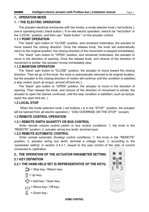
1、OPERATION MODE1. 1 THE ELECTRIC OPERATIONThe actuator electrical enclosures with two knobs, a mode selector knob ( red buttons ), one is operating knob ( black button ). If on-site electric operation, need to be “red button” in the "LOCAL” position, and then use " black button " on the actuator control.1.1.1 POINT OPERATIONThe “black” spin button to "CLOSE" position, and remained motionless, the actuator to move toward the closing direction. Once the release knob, the knob will automatically return to the original position, the closing direction of the movement is stopped immediately;The “black” spin button to "OPEN" position, and remained motionless, the actuator to move in the direction of opening. Once the release knob, and closure of the direction of movement is similar, the actuator moves immediately stop.1.1.2 MAINTAIN OPERATIONThe “black” spin button to "CLOSE" position, the actuator to move toward the closing direction. Then let go of the knob, the knob is automatically returned to its original location, but the actuator to the closing direction of motion will continue until the condition is satisfied, a stop motion (such as torque, arrived off limit etc.);The “black” spin button to "OPEN" position, the actuator to move in the direction of opening. Then release the knob, and closure of the direction of movement is similar, the actuator to open the Games continued, until the stop condition is satisfied ( such as torque, reach the open limit etc. ).1.2 LOCAL STOPWhen the mode selection knob ( red buttons ) is in the "STOP " position, the actuator will be banned from all electric operation ( " ESD OVERRIDE ON THE STOP " except).1.3 REMOTE CONTROL OPERATION1.3.1REMOTE SWITH QUANTITY OR BUS CONTROLEnter remote volume control switch or bus control conditions: 1, the knob in the "REMOTE" position; 2, actuator wiring box tenth, terminal input.1.3.2 REMOTE AUTOMATIC CONTROLEnter remote automatic (Analog) control conditions: 1, the knob in the "REMOTE" position; 2, actuator wiring box tenth, terminal a voltage input; 3, according to the “parameter setting" in section 2.4.3.1, issued to the user control of the ratio of currentconducted to calibration.2、THE OPERATION OF THE ACTUATOR PARAMETER SETTING2.1 KEY DEFINITION2.2.1THE HAND-HELD SET IS REPRESENTATIVE OF THE KEYS:= Stop key / Return key;= Up key;= Add key / Open key;= Minus key / Off key;= Down key;= Confirm key;2.2.2MODE BUTTON REPRESENTS THE KEY:Confirm key: mode button from the "STOP" - > “LOCAL" position, hereinafter referred to as the "Confirm key;Return key: mode button from the "STOP" - > “REMOTE" position, hereinafter referred to as the "return key;2.2.3THE OPERATION BUTTON REPRESENTS THE KEYDown key: the operating button - > " CLOSE" position, hereinafter referred to as the "Down key;Add key: the operating button - > " OPEN" position, hereinafter referred to as the "Add key;2.2 LCDThe actuator is equipped with a bitmap type liquid crystal display. Its layout is the region Ⅰ,Ⅱ,Ⅲ zone.I zone for valve position display area, the valve opening position percentage in the form of real-time display the current valve position value;II zone for the control of display area;III zone for running state and alarm information display area ( see behind the " five, alarm information." );When entering the working parameter setting menu, the LCD screen will use a unified region Ⅰ,Ⅱ,Ⅲ zone.2.3 POWER ON OR RESET2.3.1 POWER ON SELF TEST SYSTEMThe actuator after power on, the actuator control system based on instruction, program area, data region and a A/D conversion function in self. If the test were normal, LCD liquid crystal display valve position display area shows the current valve opening position percentage, alarm area contents are cleared. If the self-test one is not normal, warning zone will always show the abnormal code, the control system not to accept any operation, pending.The actuator power after initialization, the liquid crystal display screen in large font to display the percentage of valve opening. In the valve position limit position, the valve opening display simulation butterfly valve graphical display ( see below ).2.3.2 SYSTEM RESETIn any case, the mode button on the " STOP" position, the operation button is placed on the " CLOSE" position and maintain 5S above the clock, until the liquid crystal screen above the lighted indicator lights, and then release the operation knob away from the "CLOSE" position, the control system reset.2.4 WORKING PARAMETER SETTINGNote 1: in the menu operation, if the user in 1 minutes without key operation, display will automatically return to a setting screen. In addition, in the menu operation, should use the return key to exit the setup screen, before the motor rotates at a setting screen when the valve opening position.Note 2: in the menu operation, first display settings or first display setting value is set after the last stored value, the user can use this feature to view previously set value.2.4.1ENTER MENUThe mode button on the “LOCAL" position, according to the hand-held set on 1, 2, 5, 6 keys of any key can enter the working set menu. Or will the mode button on the " STOP" position, the operation button is placed on the " OPEN" position and maintain 3S above the clock, control system into the working set main menu.Note: In order to behind the narrative and display with convenient, " [ ] " the representationof the selected menu, in the liquid crystal screen menu display, the selected item is to reverse display mode ( i.e. black white ) indicating the cursor position; not the selected itemin a conventional manner ( i.e. black text on a white background ).2.4.2 BASIC SETTINGS MENUIn [ 1 ] on the menu, with a "Up key " or " Down key " to select the desired item, then press " Confirm key ", show will enter the corresponding menu as shown above. Basic settings [ 2 ] on the menu of 4 options, namely, " CHANGE CLOSE DIRECTION ", " LOCAL CONTROL MODE ", " ACCEPT VALVE LIMIT CLOSED VALVE LIMIT OPEN " and " ACCEPT ".2.4.2.1 CHANGE CLOSE DIRECTIONIn [ 2 ] on the menu " CHANGE CLOSE DIRECTION ", the selected item, the line of the right will show a previously set value ( " CLOCKWISE " or " COUNTER CLOCKWISE " ). Click the " Return key" to return to the previous menu, does not alter the previously set value. Users can use these characteristics to query a previously set value ( following similar, no longer has the ). Use the "Add key ", " Minus key " can make the setting value in " CLOCKWISE " and " COUNTER CLOCKWISE " switching between. Use the "Confirm key " save the selected set value.2.4.2.2 LOCAL CONTROLIn [ 2 ] on the menu " LOCAL CONTROL MODE ", the selected item, the line of the right will show a previously set value ( " INCHING " or " MAINTAIN " ). Use the "Add key ", " Minus key " can make the setting value in " INCHING " and " MAINTAIN " switching between. Use the "Confirm key " save the selected set value.2.4.2.3 ACCEPT VALVE LIMIT CLOSEDLimit set order is unlimited, the user can set off again on a set, can also open a set off again.In [ 2 ] on the menu, " ACCEPT VALVE LIMIT CLOSED " selected item, the rows of the right will show the current absolute encoder output current location for thousands of ratio of (0~ 1000). Manual mode will be available to the valve rotation limit; can also be mode button on the " LOCAL " position, according to the hand-held set is Open key/Off key or by operating the button with means of the electric motor valve rotating to limit at. Click the " Confirm key ", LCD screen above the red indicator light flashing 2 exhibit of lanterns before, said actuator has the position calibration for clearance limit. According to the " Confirm key " to " Return key " before, do not set off the limit, and return to the previous menu.2.4.2.4 ACCEPT VALVE LIMIT OPENIn [ 2 ] on the menu, " ACCEPT VALVE LIMIT OPEN " selected item, the rows of the rightwill show the current absolute encoder output current location for thousands of ratio of (0~1000). Available manually valve rotates to the open limit; can also be mode button on the "LOCAL" position, according to the hand setting device on a "Open key/Off key " or by the operating knob with means of the electric motor valve rotating to open limit position. Click the " Confirm key ", when the liquid crystal screen above the green indicator exhibit of lanterns flashing 2 after light, said actuator has the position calibration for open limit. According to the " Confirm key " to " Return key " before, do not set the open limit, and return to the previous menu.Note 1: 1000 ratio 0 and 1000 respectively for absolute encoder minimum code value and the maximum code value, the two is the coincidence. Open, close to set the limit of the whole trip can after this point, but should guarantee the full travel beyond that represent the range of absolute encoder. Note 2: if the set limit is set at one end and another end limit, should not withdraw from the original set, and run to the other end of the limiting office, then enters the other end limit setting item for confirmation, otherwise there will be a " blocking " warning error.2.4.2.5 CHANGE THE LCD DISPLAYIn [ 3 ] on the menu, with a "Up key " or " Down key " selected " CHANGE THE LCD DISPLAY", the bank's right will show a previously set value ( " INVERT " or " POSITIVE " ). Use the "Add key ", " Minus key " to select the desired value, use the "Confirm key " save the selected revision.2.4.3 SECOND SETUPIn [1] on the menu, selected " SECOND SETUP" and press "confirm " [ 3 ] into the menu. As shown in the following illustration.2.4.3.1 4-20mA OF ACC. CALIBRATIONIn [ 3 ] on the menu, with a "Up key " or " Down key " selected " 4-20mA OF ACC. CALIBRATION" and press "Confirm key " [ 4 ] on screen display menu content.When a user sends the actuator 4mA~ 20mA current and actuator previous calibration value is different, use this function is issued to the user 's current recalibrated, causes the actuator and the user's 4mA~ 20mA current transmission device with the same measure, in order to improve the accuracy of the actuator control system.In order to describe convenience, defines 4mA signal low-end (referred to as low signal ), 20mA signals for high-end (referred to as the high letter).CALIBRATE 4mA FOR ACC in [ 4 ]: on the menu, with a "Down key " selected " CALIBRATE 4mA FOR ACC", the bank's right will show the actuator to collect the control current value ( mA ); the user can send the control current to the actuator end of the signal, and when the current is stable after according to the " Confirm key " save the collected current value.CALIBRATE 20mA FOR ACC in [ 4 ]: on the menu, with a "Down key " selected " CALIBRATE 20mA FOR ACC", the bank's right will show the actuator to collect the control current value ( mA ); the user can send the control current to the actuator end signal, and to the current stability according to the " Confirm key " save the current value.At any time the user can control the current calibration menu to query the user sends the current value, but in the control current signal without calibration, inquires into the value is not accurate.2.4.3.2 POSITIONING CONTROL SETUPIn [ 3 ] on the menu, with a "Up key " or " Down key " select " POSITIONING CONTROL SETUP" and click " Confirm key " [ 5 ] on screen display menu content.2.4.3.2.1 DEADBAND ADJUSTMENTDead meaning: the functions of the remote automatic control method. In this mode, the actuator according to the control current to calculate the user wishes to valve position value, then the value and the current valve position values are compared, and if the absolute value of the difference is greater than the zone value, the actuator to action, so that the current valve valve position close to the goal orientation. If the current valve position and the user wants the valve position of the absolute value of the difference in the dead zone range, then the actuator stop motion. Set proper dead-time prevents the actuator in a valve position oscillation.In [ 5 ] on the menu, with a "Down key " selected " DEADBAND ADJUSTMENT " item, the line of the right will show a previously set value ( 0.1%~9.9% ) or " SELF ADAPTING ". The user can use the " Add key ", " Minus key " to change the deadband values. Select the desired deadband value, using " Confirm key " to save your changes.2.4.3.2.2 POLARITY FOR ACCPOLARITY FOR ACC: in current control mode, the lower end of the signal ( 4mA current)Note corresponding to the valve opening position value.In [ 5 ] on the menu, with a "Down key " selected " POLARITY FOR ACC", the bank's right will show a previously set value " 4mA = CLOSED " or " 4mA = OPEN ". The user can use the " Add key ", " Minus key " to change the selection. Select the desired value, using the " Confirm key " to save your changes.Note: the current and low current corresponding to the valve opening position values are mutually exclusive. For example, when setting the low-side current corresponding valve position switch, current automatic corresponding valves full open. Conversely, low signal valve set corresponding valve fully open, the high-end automatic current corresponding to the valve position switch.2.4.3.2.3 ACTION ON LOSS SIGNALLost letter: when the actuator is in the remote automatic control mode, and the control current is less than the low current 1/2, actuators that control signal is lost, referred to as the lost letter.ACTION ON LOSS SIGNAL:ACTION ON LOSS SIGNAL defined in the event of lost letter when the actuator should run into position. The "STAY UP ", " CLOSED ", " OPEN " 3 selectable values. The " STAY UP " refers to remain in situ.In [ 5 ] on the menu, with a "Down key " ACTION ON LOSS SIGNAL " selected " item, the bank's right will show a previously set value ( " STAY UP " or " CLOSED " or " OPEN " ). Use the "Add key ", " Minus key " to select the desired value, use the "Confirm key " save the selected revision.2.4.3.2.4 BRAKE TIME WITH TURN IN REVERSEBRAKE TIME WITH TURN IN REVERSE refers to the movement of the actuator to the target position, and then a short reverse rotation, to compensate for actuator motion inertia, to improve the control precision of the objective.In [ 5 ] on the menu, with a "Down key " " BRAKE TIME WITH TURN IN selected REVERSE " item, the bank's right will show the previous set of actuators rotate in reverse time value ( mS ). Use the "Add key ", " Minus key " in 0~ 50mS time range to select the desired value ( 0mS said without brake ), using " Confirm key " to save your changes.2.4.3.3 ESD SETUPIn [ 3 ] on the menu, with a "Up key " or " Down key " select the "ESD SETUP" and click " Confirm key " [ 6 ] on screen display menu content. : select “ESD SETUP” and " Add key ", according to the " Minus key " will cause the system reset, is a normal phenomenon ( the factory when tested with ).2.4.3.3.1 ESD ACTIONESD: refers to emergency situations (i.e., the actuator control signal terminal to detect ESD ESD appear on the effective signal) actuator which actions to perform. There are 3 kinds of ESD action: " OPEN ", " CLOSED " and " STOP ".In [ 6 ] on the menu, with a "Up key " or " Down key " selected " ESD ACTION " item, the line of the right will show a previously set value ( " CLOSED " or " OPEN " or " STOP " ). Use the "Add key ", " Minus key " to select the desired value, use the "Confirm key " save the selected revision.2.4.3.3.2 ESD ACTION WHEN ESD SIGNAL ISThe actuator ESD control signal terminal input signal can be two levels: no voltage signal is called the low level, a voltage signal is called the high level.In [ 6 ] on the menu, with a "Down key " " ESD ACTION WHEN ESD SIGNAL selectedIS " item, the bank's right will show a previously set value ( " ABSENT " or " PRESENT " ). Use the "Add key ", " Minus key " to select the desired value, use the "Confirm key " save the selected revision.2.4.3.3.3 ESD OVERRIDE ON THERMALESD OVERRIDE ON THERMAL refers to " MOT.OVERTHERMAL " even if the alarm will execute ESD control action, otherwise, to stop the implementation of ESD control action.In [ 6 ] on the menu, with a "Up key " or " Down key " ESD OVERRIDE ON THERMAL " selected " item, the bank's right will show a previously set value ( " YES " or " NO " ). Use the " Add key ", " Minus key " to select the desired value, use the "Confirm key " save the selected revision.2.4.3.3.4 ESD OVERRIDE ON THE STOPESD OVERRIDE ON THE STOP refers to the even mode button in position "STOP" to perform ESD control action, otherwise, to stop the implementation of ESD control action.In [ 6 ] on the menu, with a "Up key " or " Down key " " ESD OVERRIDE ON THE STOP selected " item, the bank's right will show a previously set value ( " YES " or " NO " ). " Add key ", " Minus key " to select the desired value, use the" Confirm key " save the selected revision.2.4.3.4 NETWORK SETUPNot When the actuator through the Profibus field bus control, need to enter the items set in advance. If using a dual channel redundant configuration, need to set of channels and II channel address, or simply set Ⅰchannel address. Channel address refers to the bus control can be the main control system ( Master) and their identification code. e: This machine address reset, the actuator must first off, turn power can guarantee the normal work of the Profibus bus control.In [ 3 ] on the menu, with a "Up key " or " Down key " select the "NETWORK SETUP" and click " Confirm key " [ 7 ] on screen display menu content.2.4.3.5.1 SLAVE ADDRESS1In [ 7 ] on the menu, with a "Up key " or " Down key " select the "SLAVE ADDRESS1 " item, the right will be displayed before the set address value. Use the " Add key ", " Minus key" may be in the 1 to 126 range selection of the desired value, use the "Confirm key " tosave your changes.2.4.3.5.2 SLAVE ADDRESS2In [ 7 ] on the menu, with a "Up key " or " Down key " select the "SLAVE ADDRESS2 " item, the right will be displayed before the set address value. Use the " Add key ", " Minus key" may be in the 1 to 126 range selection of the desired value, use the "Confirm key " to save your changes.2.4.3.6 TWO-SPEED TIMERTWO-SPEED TIMER refers to the operation of the actuator is not continuous, but stop-and-go. This operation is directed to those in need in the valve to be opened or closed in the process of setting the clearance action. TWO-SPEED TIMER allows the actuator topulsating implementation of closing / opening action, so as to effectively increase the travel time, to prevent the hydraulic shock and fluid surge.If the choice is "DISABIE ", the operation of the actuator is normal continuous operation process; if you choose to "ENABLE", show [ 8 ] to enter the menu, according to the requirements of users on TWO-SPEED TIMER [ 8 ] on the menu in the child set.2.4.3.6.1 START POSITION IN OPENINGSTART POSITION IN OPENING refers to the actuator in the opening direction during the operation of opening “TWO-SPEED TIMER “start position. Use the "Add key ", " Minus key " in 0~100% opening range to select a desired value, use the "Confirm key " to save your changes.2.4.3.6.2 STOP POSITION IN OPENINGSTOP POSITION IN OPENING refers to the actuator in the opening direction of operation process termination " TWO-SPEED TIMER " end position. Use the "Add key ", " Minus key " in 0~ 100% opening range to select the desired value ( Note: STOP POSITION IN OPENING must be greater than START POSITION IN OPENING ), "Confirm key " to save your changes.2.4.3.7.3 PULSE ON IN OPENINGPULSE ON IN OPENING refers to the actuator in the opening direction of implementation of "TWO-SPEED TIMER " operation in each TWO-SPEED TIMER required during operation of the travel value. Use the "Add key ", " Minus key " in 2~ 100% opening range to select a desired value, use the "Confirm key " to save your changes.2.4.3.6.4 PULSE OFF IN OPENINGPULSE OFF IN OPENING refers to the actuator in the opening direction of implementation of "TWO-SPEED TIMER” operation in each discontinuous stop required during the time value. Use the "Add key ", “Minus key " in 1 to 255 seconds to select a desired value, use the "Confirm key " to save your changes.2.4.3.6.5 START POSITION IN CLOSINGSTART POSITION IN CLOSING refers to the actuator in the closing direction during the operation of opening “TWO-SPEED TIMER " start position. Use the "Add key ", " Minus key " in 0~100% opening range to select a desired value, use the "Confirm key " to save your changes.2.4.3.6.6 STOP POSITION IN CLOSINGSTOP POSITION IN CLOSING refers to the actuator in the closing direction in the running process of the termination of “TWO-SPEED TIMER " end position. Use the "Addkey ", " Minus key " in 0~100% opening range to select the desired value ( Note: STOP POSITION IN CLOSING must be less than START POSITION IN CLOSING ), "Confirm key " to save your changes.2.4.3.6.7 PULSE ON IN CLOSINGPULSE ON IN CLOSING refers to the actuator in the closing direction of implementation of "TWO-SPEED TIMER” operation in each intermittent operation required during operation of the travel value. Use the "Add key ", " Minus key " in 2~ 100% opening range to select a desired value, use the "Confirm key " to save your changes.2.4.3.6.8 PULSE OFF IN CLOSINGPULSE OFF IN CLOSING refers to the actuator in the closing direction of implementation of "TWO-SPEED TIMER” operation in each discontinuous stop required during the time value. Use the "Add key ", " Minus key " in 1 to 255 seconds to select a desired value, use the "Confirm key " to save your changes.2.4.4 POS.FDBK.CALThe actuator will current location to 4mA~20mA current delivered to the control room. When the user that sent 4mA ~20mA current is not on time, you can use this feature to be calibrated. In [ 1 ] on the menu, select " POS.FDBK.CAL" and press the " Confirm key " [ 9 ] into the menu. As shown in the following illustration.2.4.4.1 ADJUST 4MA FOR CPFIn [ 9 ] on the menu, with a "Up key " or " Down key " selected " ADJUST 4MA FOR CPF", the bank's right will show the previously set value. When the actuator force feedback 0% valve position corresponding to the current value (4mA), in order to offer user detection. If the 4mA current feedback is not accurate, the user can press the " Add key ", " Minus key " to adjust the actuator feedback current value, meet the requirements for " Confirm key " to save your changes.2.4.4.2 ADJUST 20MA FOR CPFIn [ 9 ] on the menu, with a "Up key " or " Down key " selected " ADJUST 20MA FOR CPF", the bank's right will show the previously set value. When the actuator force feedback 100% valve position corresponding to the current value ( 20mA ), in order to offer user detection. If the 20mA current feedback is not accurate, the user can press the " Add key ", " Minus key " to adjust the actuator feedback current value, meet the requirements for " Confirm key " to save your changes.2.4.4.3 POLARITY FOR CPFIn [ 9 ] on the menu, with a "Up key " or " Down key " select " POLARITY FOR CPF", the bank's right will show the previously set value ( 4MA=CLOSED or 4MA=OPEN ). The lower end of said feedback current value ( 4mA ) on behalf of the valve position value ( close / open ). Select the desired value, using the " Confirm key " to save your changes." POLARITY FOR CPF" is selected, the feedback current value ( 20mA ) on behalf of the valve position value is then determined, and the low-side current corresponding to the valve opening position values are mutually exclusive. Such as " POLARITY FOR CPF" selected " off ", is the current representative of the valve position value to "4MA= OPEN ".2.4.5 STATUS MENUIn [1], “SIGNAL VIEW menu, select " and press "Confirm key " [ 10 ] into the menu. As shown in the following illustration.2.4.5.1MODE BUTTON POSITIONIn [ 10 ] on the menu, with a "Up key " or " Down key " " POSITION OF THE SELECTOR KNOB selected " item, the right hand will display " mode button " location. The user can on the knob position query:When the mode knob ( red buttons ) in " STOP " position, [ 10 ] menu " POSITION OF THE SELECTOR KNOB" right "STOP " as normal, otherwise is not normal;When the mode knob ( red buttons ) in " LOCAL " position, [ 10 ] menu " POSITION OF THE SELECTOR KNOB" right "LOCAL " as normal, otherwise is not normal;When the mode knob ( red buttons ) in " REMOTE " position, [ 10 ] menu " POSITION OF THE SELECTOR KNOB" right "REMOTE " as normal, otherwise is not normal.Note: in this way, with the knob “return “operation does not play role.2.4.5.2THE OPERATION BUTTON POSITIONIn [ 10 ] on the menu, with a "Up key " or " Down key " " POSITION OF THE OPERATOR KNOB selected " item, the bank's right will show the mode button position. The user can on the knob position query:When the operation knob ( black button ) in " OPEN " position, [ 10 ] menu " POSITION OF THE OPERATOR KNOB" right "OPEN " as normal, otherwise is not normal;When the operation knob ( black button ) in " CLOSE " position, [ 10 ] menu " POSITION OF THE OPERATOR KNOB" right "CLOSE " as normal, otherwise is not normal;When the operation knob ( black button ) in " NOTHING " position, [ 10 ] menu " POSITION OF THE OPERATOR KNOB" right "NOTHING " as normal, otherwise is not normal.Note: in this entry, with the operation knob " down" operation or the query "CLOSE" position when the screen to display " CLOSE " after a second move to the next item.2.4.5.3 REMOTE OPEN SIGNAL APPEARIn [ 10 ] on the menu, select " REMOTE OPEN SIGNAL APPEAR", the right to display。
电动阀说明书
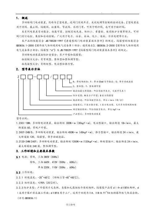
1.概述多回转阀门电动装置,简称为Z型电装,是阀门实现开启、关闭或调节控制的驱动设备。
Z型电装适用于闸阀、截止阀、隔膜阀、柱塞阀、节流阀、水闸门等。
可用于明杆阀,也可用于暗杆阀。
本系列电装具有功能全、性能可靠、控制系统先进、体积小、重量轻、使用维护方便等特点。
可对阀门实行远控、集控和自动控制。
广泛用于电力、冶金、石油、化工、造纸、污水处理等行业。
本产品的性能符合JB/T8528-1997《普通型阀门电动装置技术条件》的规定。
隔爆型的性能符合GB3836.1-2000《爆炸性气体环境用电气设备第1部分:通用要求》,GB3836.2-2000《爆炸性气体环境用电气设备第2部分:隔爆型“d”》及JB/T8529-1997《隔爆型阀门电动装置技术条件》的规定。
多回转电动装置按防护类型分:有户外型和隔爆型;按控制方式分:有常规型、整体型和整体调节型;按连接型式分:有转矩型、电站型和推力型。
2.型号表示方法A:带现场按钮;F:带4-20mA信号输出;S:带手动减速箱:整体型;T:整体调节型输出轴最大转圈数:阿拉伯数字表示,无数字见表1防护类型:W表示户外型;B表示隔爆型输出转速:阿拉伯数字表示,单位r/min(转/分)连接型式:T表示推力型,I表示电站型,无代号为常规转矩型额定输出转矩:阿拉伯数字表示,单位kgf·m产品型式:多回转电动装置型号示例:1.Z30I-18W:多回转电动装置,输出转矩300N·m(30kgf·m),电站型接口,输出转速18r/min,最大转圈数60,常规户外型。
2.Z45T-24B/S:多回转电动装置,输出转矩450N·m(45kgf·m),推力型接口,输出转速24 r/min,最大转圈数120,隔爆型,带手动减速箱。
3.Z120-24W/240T:多回转电动装置,输出转矩1200N·m (120kgf·m),转矩型接口,输出转速24 r/min,最大转圈数240圈,整体调节型。
KFD阀门控制箱中英文说明书

额定电流(安培)调节型适用电装型号Ⅲ配型、型Ⅳ配型结构形式:、抽屉式、小型R ated current (am pere)T A djusting typeZ W Q W JQ A pplicable type of electric fitting: for ZW type and Q W type.C X G Structure from : C draw er type, X sm all C ontrol cabinet of electric valve cabinetⅢⅣ抽屉式、挂壁式、、、阀门电动装置控制箱for JQ type draw er type, G wall type K F D —— 普 通 型 KFD 系 列 Common type KFD series一、概 述 Brief introduction该系列电动阀门控制箱,是与我厂生产的ZW 型、JQ 型及QW 型阀门电动装置配套使用的电控箱,用于控制阀门的开启和关闭,可用于现场单独控制或远方集中控制。
KFD 型电控箱有抽屉式和挂壁式两种结构。
This series of control cabinet of electric valve is the one to be used together with ZW type, JQ type and QW type electric valve actuator produced by our company and to control the opening and closing of valve. It can be used in site individual control or long-distance centralized control.KFD type electric control cabinet has two kinds of structure: drawer type and wall type. Designation型号表示方法 Designation二、技术数据 T echnical data1、电源:380V 50Hz 三相四线制(特殊要求,另见)2、工作环境:(1)环境温度:—20℃~+60℃ (2)相对湿度:≤85%(20℃时)(3)周围不含强腐蚀性、易燃易爆介质及导电尘埃。
西门子 SQX32. SQX82. SQX62.电动阀门执行器 说明书

4554电动阀门执行器SQX32...SQX82...SQX62...行程20 mm• SQX32…: AC 220V 工作电压, 接受三位控制信号 • SQX82...: A C 24 V 工作电压, 接受三位控制信号 • SQX62...: A C 24 V 工作电压,DC 0…10 V 和/或 0...1000 Ω 或DC 4...20 mA 阀位信号 • 通过附加辅助开关和电位计来增强功能性 • 调节力量可达 700 N • 行程 20 mm• 不需要其他设置工具可以直接与阀体安装 • 有手动调节和位置显示功能• SQX82…U 和 SQX62U 通过UL 认证用于二通阀、三通阀 V VF …, VVG …, VPF …, VXF …, VXG …系列型号的阀门执行器, 驱动行程为20mm 。
用途应用领域符合 IEC 721-3-3 (国际电工委员会721-3-3规定) 3K5 等级 • 环境温度: -15...+50 °C• 阀内介质温度: -25...+140 °C>140°C 使用S K B...系列执行器 < 0 °C: 要求使用阀杆加热元件ASZ6.5功能异步电机可通过端子Y1或Y2 输出的三位控制信号进行控制,通过抗阻碍齿轮链及齿轮架产生所希望的阀位行程。
SQX32..., SQX82... 三位控制信号• Y1 端有电压: 阀杆收缩,阀门打开 • Y2 端有电压: 阀杆伸长,阀门关闭 • Y1 或Y2 端无电压 阀杆保持在当前位置 SQX62... 是通过端子Y 和/或R.信号进行控制。
记录的位置信号通过电子微处理器控制同步电机,电机t 通过抗阻碍齿轮链及齿轮架产生所希望的阀位行程。
SQX62, SQX62U阀位信号:DC 0...10 V 和/或0...1000 Ω 或 DC 4...20 mA• 阀位信号 Y, R 值增大: 阀杆收缩,阀门打开 • 阀位信号 Y, R 值减小: 阀杆伸出,阀门关闭 • 阀位信号 Y, R 不变: 阀杆保持在各自原位通过调节滑片(外壳下面的电路板上) ,可实现VVF... , VVG…, VXF…, VXG…和 VPF...的流量特性从 "等百分比" 转换成 "线性"。
SIEMENS 电动液压阀门执行器 说明书
25 ... 150 mm
VXF40... (法兰)
15 ... 150 mm
VXF41... (法兰)
15 ... 150 mm
VXF61... (法兰)
15 和 25 mm
PN
6 bar 10 bar 16 bar 16 bar 16 bar 25 bar 40 bar
6 bar 10 bar 16 bar 16 bar 40 bar
和工作范围的顺序控制和工作方向的选择) • 线性或等比例流量特性的选择 • 阀位反馈 • 行程较验 • LED 状况显示 • 强制控制功能 • 有手动调节和位置指示功能 • 调节力量可达 2800 N • 直接安装在阀门上,不需要调节 • 可通过附加辅助开关、阀杆加热元件和机械行程逆变器来增强功能性
? G0
Fully open Fully closed
Input override
? 0 ...1000 Ω
0 ...100 %
(Signal priority)
Pump Solenoid
Y
DC 0 ...10 V or
0 ...100 %
Input
Valve Seat Detection
Stroke
型号 SKB... 行程 20 mm 标准版
功能增强版
SKC... 行程 40 mm 标准版
功能增强版
2/13 Siemens Building Technologies HVAC Products
型号
工作电压
SKB62 SKB62U *
AC 24 V
SKB60 SKB62UA * AC 24 V
控制 (控制信号)
– 控制信号的可选性 (DC 0 ... 10 V / 4 ... 20 mA / 0 ... 1000 Ω) – 流量特性的可选性 (等比例 / 线性) – 阀位反馈 – 行程较验 – LED 状态显示 – 通过端子Z 的强制控制 • SK...62UA 功能增强版: – 行程限位控制 – 可调起始点和工作范围的顺序控制 – 工作方向的选择 (正向动作 /反向动作) • 有辅助开关的安装空间 • 如果需要可使用阀杆加热元件 • 如果需要可安装机械行程逆变器 (只适用SKB...) • SK...62U 和 SK...62UA 执行器通过UL (美国电器质量标准)认证
西门子楼宇科技暖通空调产品4561电动液压阀门执行器说明书
AP1N4561zh 西门子楼宇科技暖通空调产品4561电动液压阀门执行器行程 20 mm SKD32... SKD82... SKD62... SKD60•SKD32...:工作电压为 AC 230 V,三位控制信号•SKD82...:工作电压为 AC 24 V,三位控制信号•SKD6…:工作电压为 AC 24 V、DC 0–10 V、4–20 mA 或 0–1000 Ω阀位信号•SKD6...:可选择流量特性、阀位反馈、行程调校、LED 状态指示、优先控制•SKD62UA:具有选择动作方向、行程限位控制、可调起始点和行程范围的顺序控制和附加防冻保护监控信号 QAF21…及 QAF61…等功能•驱动扭矩达 1000 N•带或不带弹簧复位功能•直接安装在阀门上,无需调节•有手动调节和位置指示功能•可通过附加辅助开关、电位计、阀杆加热器和行程逆变器来增强功能性•SKD...U 通过 UL 认证用途用于西门子二通阀和三通阀 VVF...、VVG…、VXF…和 VXG... 系列阀门,驱动行程为20 mm,应用于暖通空调系统中作为控制阀或安全截止阀。
2/16型号概览 弹簧复位 [秒] 驱动时间 [秒]型号工作电压 [V]驱动信号功能 时间 开启 关闭 增强功能SKD32.50 SKD32.51 120 120 SKD32.21 AC 230有8 3010SKD82.50 SKD82.50U *SKD82.51 SKD82.51U * 三位有8 120120SKD62 SKD62U * 有 15 标准版SKD60功能增强版SKD62UA *AC 24DC 0–10V , 4–20 mA ,或 0–1000 Ω有153015有 1)1)动作方向、行程限位控制、顺序控制、附加信号* UL 认证版本型号 描述适用执行器 安装位置ASC1.6 辅助开关 SKD6…ASC9.3 双位辅助开关 ASZ7.3 电位计 1000 Ω ASZ7.31 电位计 135 Ω ASZ7.32 电位计 200 Ω SKD32… SKD82…1 x ASC 1.6 或 1 x ASC9.3 或 1 x ASZ7.3 或 1 x ASZ7.31 或1 x ASZ7.32 ASZ6.5 阀杆加热器 AC 24 V 1 x ASZ6.5 ASK50机械行程逆变器SKD … 1 x ASK50订货订货时请说明数量、品名及型号。
电动阀门单体调试手册英文版
Commissioning Scheme of Motor-operated ValveContent1 Basis of preparation (2)2 Project Outline and Construction Scope (2)3 Allocations of Construction Personnel, Personnel Qualifications and Division of Duty (2)4 Machines & Tools, Measuring Apparatus and Safety Protection Articles for Erection (3)5 Construction Condition and Preparatory Work before Construction (3)6 Working Procedures, Method and Requirement (4)7. Quality Control and Acceptance (9)8. Requirement and Measure of Safety, Civilized Construction and Environment Management (10)1 Basis of preparation1.1 Service manual supplied by manufacture1.2 Design drawing of design institute2 Project Outline and Construction Scope2.1 Project OutlineThere is various model and many suppliers for motor-operated valves in this project. Motor-operated valves device are widely used in thermal piping of boiler drain system, soot blower system, feedwater system, turbine condensate water, drain, main steam, auxiliary steam, open (close) cycle cooling water, circulating water.2.2 Construction ScopeCommissioning of all the motor-operated valves included in BTG package3 Allocations of Construction Personnel, Personnel Qualifications and Division of Duty3.1 Allocation of Construction Personnel3.2 Qualifications of Construction Personnel3.2.1 The construction personnel of motor-operated valves commissioning must be trained with special skills, know structure and operating principle of motor-operated valves device and master commissioning method and step.3.2.2 Commissioning personnel should be familiar with operation method and can operate skillfully.3.2.3 Commissioning personnel should understand production technological process and be clear about erection location of device.3.2.4 Commissioning personnel must be clear with regulations of construction safety, master some first aid treatment, qualified in safety exam and be in good physical &mental condition during working.3.2.5 Two commissioning persons are demanded for each motor-operated valve at least i.e. one person takes charge of operating valves in distribution board room; meanwhile the other takes charge of commissioning of positioning and feedback signal.A safety inspector is necessary when commissioning on danger area at site.4 Machines & Tools, Measuring Apparatus and Safety Protection Articles for Erection5 Construction Condition and Preparatory Work before Construction5.1 Commissioning personnel must read service manual of device, be familiar with structure and working principle of motor driving actuator of valves, master method and step of commissioning and be clear with matters needing attention during commissioning.5.2 Commissioning tools which inspected qualified must be ready.5.3 Understand production work technological process and make clear erection location of device.5.4 Be familiar with location of motor-operated valves in thermal system and flow direction of system medium.5.5 Check wiring diagram of motor-driven actuator of valves with design drawing, modify if any discrepancy and guide assist wiring personnel to complete modification of site wiring.5.6 Erection of valves is finished, electric part is dry, wiring finished, label is clear, and power supply of distribution board is ready for charging and power voltage is qualified before site commissioning. Scaffold for working at high is fixed and reliable.5.7 Illumination for control panel and local must be in good condition. It is clean inside distribution panel and barrier that block commissioning at local must be cleared.5.8 Technology system is ready for commissioning and actuation of valves will not induce system safety problem. It must be approved by relevant party to operate valves of thermal system piping which is put into operation. Valves commissioning must be approved by trial operation department during commissioning period and “Permission to Work” is needed.5.9 DCS system works normally, which can indicate device status and give control instruction.6 Working Procedures, Method and Requirement6.1 Work Procedure Flow Chart6.2 Operation Method and RequirementCommissioning content of switch motor-operated valve is described only due to too much kinds of motor-operated and only pushbutton or location feedback device is added for the other kinds of motor-operated valve.6.2.1 Check Control Loop of ValvesCheck that secondary wiring of control loop and primary wiring conform to design requirement, meanwhile check the capacity of fuse or automatic air switch match with motor capacity. Check whether wiring of distribution box of motor-operated valve-DCS, local motor-operated valves-wiring of DCS is correct or not to make sure it will not affect DCS. Attention shall be paid to safety if somebody operates at DCS side.6.2.2 Measure Insulation Resistance of Control DeviceMeasure insulation resistance of control loop to ground and motor winding using 500V megger and its value >0.5 MΩ.6.2.3 Check whether it is ready for commissioningVisually inspect wiring of motor-operated valves is finished, flange bolts are fastened, and piping is fixed. Make sure commissioning the valve will not influence thermal system, otherwise inform trial running department and adopt isolation measure. Scaffold is needed if working at high.6.2.4 Measure DC Resistance of MotorMeasure DC resistance between three phases of motor for the motor-operated valves that are not integral and three-phase resistance should be basically balanced.6.2.5 Change Control Loop to Crawl ModeDisassemble self-hold contact to make it from crawl mode to continuous mode.6.2.6 Hand Operate Motor-Operated Valve to Center Position6.2.7 Check Actuating Direction of ValvesMake operation power and power supply charged to test switch operation direction which shall be same with actual switch direction, otherwise stop motors, cut all the power, change phase sequence of motor incoming power and test again.6.2.8 Check Control Function of Travel SwitchWhen valves are open, operate travel switch on open position, so that valves shall stop; when valves are close, operate travel switch on close position, so that valves shall stop.6.2.9 Check Control Function of Moment SwitchWhen valves are open, operate moment switch on open position, so that valves shall stop; when valves are close, operate moment switch on close position, so that valves shall stop.6.2.10 Adjust Moment Limit Mechanism6.2.10.1 Adjusting of Moment Switch on Close PositionMoment switch is already adjusted when leave factory, so just check at site. If it is against requirement, adjusting is needed. For the general (travel switch) motor operated valves, first close valves completely, adjust from the min. moment, and rough adjust fit fine adjust it until according with requirement. Check whether moment switch react with torque spanner with torque operating value requested by manufacture, otherwise adjust torque operating value. For the motor operated valves which will close under over-torque value, make sure first travel switch on close position react, then moment switch on close position react to stop motor operated valves running during the close process, adjust position of travel switch to meet requirement if torque value is acceptable.6.2.10.2 Adjusting of Moment Switch on Open PositionIt is the same with adjusting of moment switch on close position, but torque value for open position must be bigger than that for close position.The said adjusting is under no-load and no medium pressure. Check whether it can be closed completely under certain pressure and temperature, otherwise increase properly torque value till close completely and can open. Commissioning personnel shall confirm correct location of valves with mechanical personnel during commissioning process.6.2.11 Adjusting of Travel Limit Mechanism6.2.11.1 Adjusting of Control Mechanism for Travel on Close Position1. Close valves deadly by hands, residue is not needed for working medium under 150℃, 1/4-1/2 circle should be reserved for working medium on 150-300℃, and 3/4-1circle for that above 300℃.2. Push crown bar of travel control, rotate 90 degree and hold to make active pinion disengage from gear of counter single-digit.3.Rotate adjusting shaft on close position as per arrow direction indication to make gear match well, and then open by some circles by motor, at last close valves by motors to check whether travel for close position accord with requirement, if not, re-adjust as per the above steps.6.2.11.2 Adjusting of Control Mechanism for Travel on Open Position1. Open valves to needed position by hands, which within 85-90% of total travel of gate valves, and within 100% of total travel for butterfly valves, then push control crown bar of travel and rotate by 90 degree, than adjust travel switch on open position as per arrow direction until travel switch react.2.Loosen crown bar to make it out, then rotate adjusting shaft slightly, close it by certain circles by motor and then open to position to check whether travel accordS with requirement, re-adjust as per the above steps if not.3. If there is clear on-off sign, adjust travel switch as per the sign. Inform maintenance personnel to cooperate commissioning to make sure its travel position, if there is no clear sign so that travel position can not be confirmed.6.2.11.3 Make full travel react 2-3 times by motor, and check whether travel switch accords with requirement, i.e. repeatability error ≤ 4%, and record full travel time.Calculation of repeatability errorδ=|Ln+1-Ln|/LnLn+1— travel measured on the n+1 times testLn— travel measured on the n times test6.2.11.4 Make micro-gap switch of flashing device contact with cam if flashing requirement designed. Micro-gap switch reacts one times if output shaft rotates one circle.6.2.12 Change loop back to self-holding modeConnect self-holding contact into loop to change crawl to continuous react.6.2.13 Record Commissioning ParameterRecord commissioning parameters of valves such as No, model, specification, manufacture, production No. actuating time of full stroke and insulation resistance etc.6.2.14 Clean Commissioning SiteRecover valves to original position before commissioning, cut off power, install cover, lock local control box and recover original device maintenance & protection device after commissioning completed.6.3 Special Technical MeasureIt must be ensured before charging that site commissioning personnel ready, motor insulation resistance acceptable, communication between operator and site personnel free and sign of power switch and control loop according with local valves location.It must be ensured that valves are ready for commissioning and commissioning will not affect thermal system.Cut power and control power of motors before modify wiring and adjust local travel switch and torque switch.7. Quality Control and Acceptance7.1 Quality Control StandardsCommissioning of motor operated valves is as per requirement of <Criterion for Quality Acceptance and Evaluation of Thermal Power Construction-Thermodynamic Instrument and Control Device>.7.2 Setting of Intermediate Control Witness Point: None7.3 Setting of Intermediate Process IntersectionMotor operated valves will be released to commissioning department of main project and operating department to do operation test after valves commissioning completed.7.4 Process Requirement and Quality Assurance Measure7.4.1 Make sure wiring arrangement well and pulling at random is strictly forbidden during wiring modification.7.4.2 Marking at random on surface of panel and valve by marker is strictly forbidden.7.4.3 Cover of valves should be installed well with complete thread to prevent from corrosion of rain and dust. Maintenance & protection device at local should be recovered well.7.4.4 Forced operation is forbidden under valves jamming during commissioning and mechanical personnel should be informed to treat. Knocking motor operated valves by wrench and iron bar is strictly forbidden.8. Requirement and Measure of Safety, Civilized Construction and Environment Management8.1 Commissioning personnel should master and strictly obey related regulation of electric power construction safety operation rules. Wear safety shoes and dress correctly during commissioning. Safety belt must be worn when working at high. Live line modification wiring and adjustment of travel and moment switch under charging is forbidden.8.2 Application to trail running department is needed before commissioning motor operated valves, commissioning can only be started after approved and inform trial running department in time after completed. If motor operated valve to be commissioned is related with system in service, inform rail running department and get “Permit to Work”after approved and at last start commissioning after isolation measure ready. Finally inform trail running department in time to cancel “Permit to Work” after completed.8.3 Recover maintenance measure and cut working power supply of valves.8.4 Clear site and remove waste material after test complete。
- 1、下载文档前请自行甄别文档内容的完整性,平台不提供额外的编辑、内容补充、找答案等附加服务。
- 2、"仅部分预览"的文档,不可在线预览部分如存在完整性等问题,可反馈申请退款(可完整预览的文档不适用该条件!)。
- 3、如文档侵犯您的权益,请联系客服反馈,我们会尽快为您处理(人工客服工作时间:9:00-18:30)。
B H Montageanleitung H ?l Mounting instructions
Q Instructions de montage
M on te rin g s in s tru k tio n
CD M ontagehandleiding D Istruzioni di montaggio D As© 门nusohjo
Risk for skada vid trasig holje eller kapa Demontera ALDRIG stalldonet fran ventilen (kringflygande delar) Demontera ventil och stalldon som en enhet S kicka till S iem ens fo r analys och skrotning M ontera ny ventil och stalldon enligt m onteringsanvisning_____________________ Letselgevaar bij gebroken huis of deksel Aandrijving nooit van afsluiter demonteren (rondvliegende onderdelen) Afsluiter en aandrijving als geheel demonteren Naar Siem ens sturen voor analyse en verwijdering M onteer nieuwe afsluiter en aandrijving volgens m ontage instructies
Risque de blessure avec la com m ande manuelle ou le couvercle casse. Ne jam ais separer le servom oteur de la vanne (pieces volantes). Dem onter la vanne et le servom oteur comme une unite entiere. Envoyer I'unite entiere a Siem ens pour analyse M onter la nouvelle va nn e et le servom oteur selon les instructions de m ontage.________
1/lHCTpyKUMfl no yciaHOBKe
B 安裝指導
a cva tM
赢
Stellantriebe Actuators Servomoteur Stalldon Servomotoren Servocomandi Toimimoottorit Actuadores Motorer Silowniki
Pericolo di lesioni con custodia o coperchio rotto Non smontare MAI I'attuatore dalla valvola (parti volanti) Sm ontare la valvola e I'attuatore insiem e come se fosse un corpo unico Inviare entrambi a Siemens per I'anaiisi e lo sm altim ento M ontare una nuova valvola e attuatore secondo le istruzioni di m ontaggio______ Loukkaantumisvaara mikali kotelo tai kansi on rikki toimilaitetta El SAA irroittaa venttiilista (lentavat osat) Irroita venttiili ja toimilaite yhtena kappaleena Laheta Siemensille tutkittavaksi ja havitettavaksi Asenna uusi venttiili ja toim ilaite asennusohjeen mukaisesti
Pohony Szelepallito motorok
K iv n T h p £ ?
npuBOflbi
执行器
74 319 0325 0 M3250
SKD32..
C irn o o
o J v D o z ..
SKD62.. SKD60
AA
A Warning
Verletzungsgefahr bei gebrochenem Gehause oder Deckel Stellantrieb NIE vom Ventil demontieren (herumfliegende Teile) VentH-Stellantriebskombination als ganze Einheit demontieren I Siemens zur Analyse und Entsorgung at vorschriftgem ass m ontieren______________________________ Risk of injury with broken housing or cover I NEVER disassemble actuator from valve (flying debris) I D ism o u n t valve an d actuator as a whole unit Send to Siem ens for analysis and disposal M ount new valve and actuator according to mounting instructions
I门struccio 门6S de m ontaje
ES M onteringsvejledning
r a Instrukcja m onta之u m M on tazn 丨navod
nm Szerelesi utm utato
m 0 5 r ) Y ^ ? z \K O n 6 o ia o r\q