tja1050中文资料
SAE J1050驾驶员视野的描述和测量--中文版
高速CAN接口,TJA1050_3
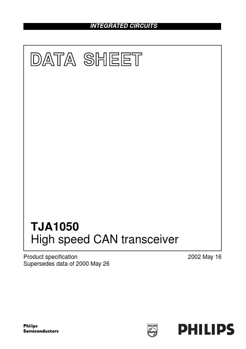
GND VCC RXD
2 3 4
TXD 1 GND 2
8 S 7 CANH CANL Vref
TJA1050T
VCC RXD 3 4
MGS375
6 5
Vref CANL CANH S
5 6 7 8
2002 May 16
3
Philips Semiconductors
PINNING SYMBOL TXD PIN 1 DESCRIPTION transmit data input; reads in data from the CAN controller to the bus line drivers ground supply voltage receive data output; reads out data from the bus lines to the CAN controller reference voltage output LOW-level CAN bus line HIGH-level CAN bus line select input for high-speed mode or silent mode Fig.2 Pin configuration.
TJA1050
The TJA1050 is the interface between the Controller Area Network (CAN) protocol controller and the physical bus. The device provides differential transmit capability to the bus and differential receive capability to the CAN controller. The TJA1050 is the third Philips high-speed CAN transceiver after the PCA82C250 and the PCA82C251. The most important differences are: • Much lower electromagnetic emission due to optimal matching of the output signals CANH and CANL • Improved behaviour in case of an unpowered node • No standby mode. This makes the TJA1050 eminently suitable for use in nodes that are in a power-down situation in partially powered networks.
一种带多种数据传输接口的工业现场多路信号检测装置[实用新型专利]
![一种带多种数据传输接口的工业现场多路信号检测装置[实用新型专利]](https://img.taocdn.com/s3/m/68046bfda8114431b90dd8f5.png)
专利名称:一种带多种数据传输接口的工业现场多路信号检测装置
专利类型:实用新型专利
发明人:杨武,张光建,陈媛,王越
申请号:CN200420105366.7
申请日:20041125
公开号:CN2743918Y
公开日:
20051130
专利内容由知识产权出版社提供
摘要:一种带多种数据传输接口的工业现场多路信号检测装置,具有多路模拟信号输入、微控制器、程序及数据存储器、控制按钮和LCD显示器。
它以51内核单片机P87C591作为微控制器,具有1个RS232接口、1个USB接口、1个以太网RJ45接口和1个CAN总线接口。
RS232接口采用电平转换器MAX202将P87C591的标准串行接口信号转换成RS232信号而获得;USB接口采用USB接口芯片PDIUSBD12;以太网RJ45接口采用RTL8019AS作为以太网控制器而获得;CAN总线接口利用
P87C591本身带的PeliCAN功能,加上CNW137光电隔离器、TJA1050总线收发器,实现与CAN总线的连接。
本仪器能够对工业现场的多路温度进行测量,并提供的多种I/O接口,充分满足与其它设备的联网和数据传输要求。
申请人:重庆工学院
地址:400050 重庆市九龙坡区杨家坪重庆工学院计算机系
国籍:CN
代理机构:重庆华科专利事务所
代理人:康海燕
更多信息请下载全文后查看。
TJA1050中文资料_数据手册_参数

2003年10月22日 4飞利浦半导体产品SPECI FI CATION高速CAN收发器 TJA1050功能说明 TJA1050是CAN协议之间的接口控制器和物理 总线.它主要用于使用波特率的高速汽车应用 60 KBAUD到1 MBAUD.它提供差分传输总线能力和差分接收器能力 CAN协议控制器.它完 全兼容 “ISO 11898”标准.限流电路保护发射机输出阶段由意外短路造成的损坏虽然电力正常或负电源电压在这种故障状态下功耗会 增加.热保护电路可保护IC免受损坏通过关闭发射机如果结温超过约165的值 C.因为发射机消耗大部分功率和功率 IC的耗散和温度降 低.所有其他 IC功能继续运行.发射机关闭状态当引脚TXD变为高电平时复位.热保护当总线短路时尤其需要电路. CANH和CANL引脚不 受汽车的保护电瞬变(根据 “ISO 7637”;参见图4).控制引脚S允许选择两种工作模式:高速模式或静音模式.高速模式是正常的操作 模式,并且是通过将引脚S连接到地面来选择.这是默认设置模式,如果引脚S未连接.但是,要确保EMI在仅使用高速应用的应用中表现 出色模式,建议将引脚S连接到地面.在静音模式下,发射器被禁用.所有其他 IC功能继续运行.无声模式是 通过连接引脚S到V CC进行 选择 ,可用于防止网络通信被阻塞,到期到一个失控的CAN控制器. “TXD主导超时”定时器电路阻止总线线路被驱动到永久主导状 态(阻塞)所有网络通信)如果引脚TXD被强制由硬件和/或软件永久为低应用失败.定时器由否定触发边沿TXD引脚.如果持续低电平 的话 TXD引脚超过内部定时器值,发送器为残疾,驾驶巴士进入隐性状态.定时器由引脚TXD上的上升沿复位.表格1 CAN收发器的功 能表; X =不在乎 V CC TXD小号 CANH CANL总线状态 RXD 4.75 V至5.25 V低低(或 FL替罪羊)高低优势低 4.75 V至5.25 V X高 0.5V CC 0.5V CC隐性高 4.75 V至5.25 V高( 飞利浦半导体产品SPECI FI CATION高速CAN收发器 TJA1050手册,全页面宽度 50 80 0 020三十 10 MGT231 40 F(MHZ) 20 40 60一个 (D B μV)图9高达50 MHZ的典型电磁发射(峰值幅度测量).数据速率为500千比特/秒.手册,全页面宽度 10 80 0 04 6 2 MGT233 8 F(MHZ) 20 40 60一个 (D B μV)图10高达10 MHZ的典型电磁发射(峰值幅度测量和峰值包络振幅).数据速率为500千比特/秒. 图1方框图.钉扎符号销描述 TXD 1传输数据输入;读入数据从CAN控制器到总线线路司机 GND 2地面 V CC 3电源电压 RXD 4接收数据输 出;读出来从公交线路到公交车的数据 CAN控制器 V REF五参考电压输出 CANL 6低级CAN总线 CANH 7高级CAN总线小号 8选择高速 模式的输入或静音模式手册,HALFPAGE 1 2 3 4 8 7 6五 MGS375 TJA1050T小号 CANH GND CANL VREF RXD VCC TXD图2引脚配置
1050操作规程

1050轧机工艺操作规程QJ/B.HT501-12技术部2006-8-2 1本规程规定了1050轧机工艺操作规程、质量控制及质量检查方法。
本规程同1050轧机工艺技术规程——QJ/B.HT501-01一、二部分等效,三、四部分与本规程合并。
一、操作规程1、操作程序原料检查→上卷→卷对中调整→引带→右卷取咬头→调整侧导板,压紧导板→测厚仪投入→轧制→甩尾捆卷→卸卷2、操作要点2.1 原料检查:按生产流程卡片,确认上料卷号。
检查卷外观质量:塔形不超标;无边裂口;表面无欠洗(无氧化铁皮)。
卷重<14T。
2.2 上卷:吊车吊卷时要稳、准,不能碰、伤钢卷端面,吊入开卷机卷筒轴线前,钢卷略高于卷筒直径,停稳,上料小车上升。
紧贴钢卷外径后,吊钩离开。
操作台操作工和上料工配合好,小车缓落,对准卷筒,将钢卷托进开卷机卷筒指定位置,然后打开捆带,同时压紧辊压下。
2.3 卷对中调整:穿带要确保钢卷在轧制中心线上,否则需用对中装置进行调整,调整对中时,应注意板边和卷端一定对齐。
2.4 穿带、右卷取咬头压头:开卷机、引料辊和校平辊,在穿带、送带到右卷取机的过程,操作工和机旁协调人员必须密切配合,采取点动,防止松圈、存套,平稳穿过轧机,对准钳口,此时用机前侧导板再次调整对中,然后进行咬头和压头。
压头时以小车两辊贴紧为好,不要用力过猛,避免损坏设备,用后及时退出。
2.5 调整侧导板和压紧导板:调整侧导板,压紧导板达到松、紧合适的程度,如果侧导板和压紧导板,经磨损不能使用,必须更换新的。
保证第一道次钢带边部不刮裂和表面不划伤。
2.6 测厚仪投入:测量原料厚度、同板差,同时观测来料板形。
2.7 轧制:2.7.1 轧制按原料材质、规格和成品厚度,分道次轧制。
各道次压下分配按表1~表7执行。
正常轧制,其工艺技术参数设定按表8执行。
第一道次轧制是关键,首先要确认下支承辊换辊后一直是水平的;轧机主轧AGC正常,液压系统正常;弯辊液压系统正常;润滑系统原料是正常的(指的是无边浪、同板差不超标、无氧化铁皮)。
tja1050中文资料

tja1050中文资料概述TJA1050是控制器区域网络(CAN)协议控制器和物理总线之间的接口。
该器件为总线提供差分发射能力并为CAN控制器提供差分接收能力。
TJA1050是PCA82C250和PCA82C251之后的第三代Philips高速CAN收发器。
最重要的区别是:由于CANH和CANL输出信号的最佳匹配,电磁辐射变得更低改善了节点未通电时的性能无待机模式。
这使TJA1050非常适合用在部分供电网络中处于节电模式的节点。
特征完全兼容ISO 11898标准高速(最大1 MBaud)电磁辐射(EME)极低差分接收器具有宽共模范围,实现了高电磁抗扰性(EMI)未通电的节点不会干扰总线线路发送数据(TXD)显性超时功能静默模式中发送器被禁用在汽车环境中对总线引脚提供抗瞬态保护输入电平兼容3.3 V和5 V器件热保护对电池和接地具有短路保护至少可连接110个节点。
当今,在自动驾驶的部分产品和原型中,所用的消费类硬件平台大都无法提供量产级别的功能安全和信息安全保障。
多年来,恩智浦和Green Hills为领先的汽车制造商和一级供应商提供功能安全技术,并已用于生产了数百万辆汽车。
此次两家公司将利用双方的经验,致力于合作解决开发SAE 2级、3级及更高级别的自动驾驶技术时遇到的问题。
恩智浦通过其S32产品系列提供安全可靠的自动驾驶功能,其中包括恩智浦针对ADAS的可扩展功能安全产品组合。
S32系列能够满足2级和3级驾驶的性能、安全与短期商业需求,并着眼于未来发布的4级和5级自动驾驶汽车,因而意义重大。
Green Hills则将其INTEGRITY RTOS技术作为安全自动驾驶软件平台的核心。
二十多年来,从飞机控制到医疗机器人,市场中需要强制防故障特性的任务和生命关键型系统纷纷选择INTEGRITY架构,这使其成为嵌入式行业中认证等级最高的RTOS。
INTEGRITY或INTEGRITY-178已经获得独立认证组织针对嵌入式应用的最高安全和保障认证,包括汽车(ISO 26262 ASIL D)、航空电子设备(DO-178 A级)、高稳健性保障(通用标准EAL 6+)、工业(IEC 61508 SIL 3)和铁路(EN 50128 SIL 4)。
SN65HVD1050_08中文资料
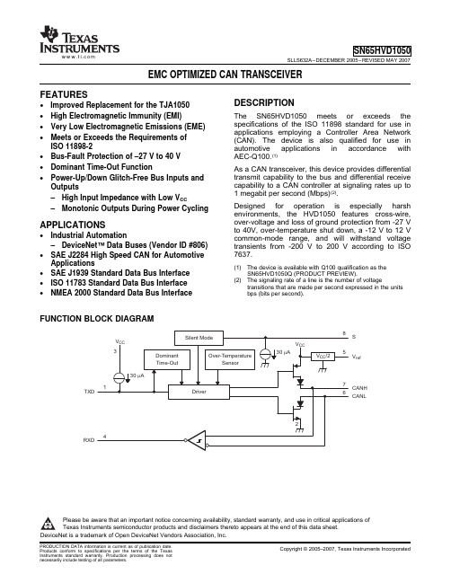
FEATURESDESCRIPTIONAPPLICATIONSFUNCTION BLOCK DIAGRAMTXDRXDSV ref CANH CANLSN65HVD1050SLLS632A–DECEMBER 2005–REVISED MAY 2007EMC OPTIMIZED CAN TRANSCEIVER•Improved Replacement for the TJA1050•High Electromagnetic Immunity (EMI)The SN65HVD1050meets or exceeds the specifications of the ISO 11898standard for use in •Very Low Electromagnetic Emissions (EME)applications employing a Controller Area Network •Meets or Exceeds the Requirements of (CAN).The device is also qualified for use in ISO 11898-2automotive applications in accordance with•Bus-Fault Protection of –27V to 40V AEC-Q100.(1)•Dominant Time-Out FunctionAs a CAN transceiver,this device provides differential transmit capability to the bus and differential receive •Power-Up/Down Glitch-Free Bus Inputs and capability to a CAN controller at signaling rates up to Outputs1megabit per second (Mbps)(2).–High Input Impedance with Low V CCDesigned for operation is especially harsh –Monotonic Outputs During Power Cyclingenvironments,the HVD1050features cross-wire,over-voltage and loss of ground protection from -27V to 40V,over-temperature shut down,a -12V to 12V •Industrial Automationcommon-mode range,and will withstand voltage –DeviceNet™Data Buses (Vendor ID #806)transients from -200V to 200V according to ISO 7637.•SAE J2284High Speed CAN for Automotive Applications(1)The device is available with Q100qualification as the SN65HVD1050Q (PRODUCT PREVIEW).•SAE J1939Standard Data Bus Interface (2)The signaling rate of a line is the number of voltage•ISO 11783Standard Data Bus Interface transitions that are made per second expressed in the units •NMEA 2000Standard Data Bus Interfacebps (bits per second).Please be aware that an important notice concerning availability,standard warranty,and use in critical applications of Texas Instruments semiconductor products and disclaimers thereto appears at the end of this data sheet.DeviceNet is a trademark of Open DeviceNet Vendors Association,Inc.PRODUCTION DATA information is current as of publication date.Copyright ©2005–2007,Texas Instruments IncorporatedProducts conform to specifications per the terms of the Texas Instruments standard warranty.Production processing does not necessarily include testing of all parameters.V refABSOLUTE MAXIMUM RATINGS (1)SN65HVD1050SLLS632A–DECEMBER 2005–REVISED MAY 2007These devices have limited built-in ESD protection.The leads should be shorted together or the device placed in conductive foam during storage or handling to prevent electrostatic damage to the MOS gates.Pin 8provides for two different modes of operation:high-speed or silent mode.The high-speed mode of operation is selected by connecting S (pin 8)to ground.If a high logic level is applied to the S pin of the SN65HVD1050,the device enters a listen-only silent mode during which the driver is switched off while the receiver remains fully functional.In silent mode,all bus activity is passed by the receiver output to the local protocol controller.When data transmission is required,the local protocol controller reverses this low-current silent mode by placing a logic-low on the S pin to resume full operation.A dominant-time-out circuit in the SN65HVD1050prevents the driver from blocking network communication with a hardware or software failure.The time-out circuit is triggered by a falling edge on TXD (pin 1).If no rising edge is seen before the time-out constant of the circuit expires,the driver is disabled.The circuit is then reset by the next rising edge on TXD.V ref (pin 5)is available as a V CC /2voltage reference.The SN65HVD1050is characterized for operation from –40°C to 125°C.ORDERING INFORMATIONMARKED PART NUMBER PACKAGE ORDERING NUMBER AS SN65HVD1050D (rail)SN65HVD1050SOIC-8VP1050SN65HVD1050DR (reel)UNITV CC Supply voltage (2)–0.3V to 7V Voltage range at any bus terminal (CANH,CANL,V ref )–27V to 40VI O Receiver output current20mA V I Voltage input,transient pulse (3)(CANH,CANL)-200V to 200V V I Voltage input range (TXD,S)-0.5V to 6V T J Junction temperature–55°C to 170°C(1)Stresses beyond those listed under "absolute maximum ratings"may cause permanent damage to the device.These are stress ratings only and functional operation of the device at these or any other conditions beyond those indicated under "recommended operating conditions"is not implied.Exposure to absolute-maximum-rated conditions for extended periods may affect device reliability.(2)All voltage values,except differential I/O bus voltages,are with respect to network ground terminal.(3)Tested in accordance with ISO 7637,test pulses 1,2,3a,3b,5,6,and 7.2Submit Documentation FeedbackCopyright ©2005–2007,Texas Instruments IncorporatedProduct Folder Link(s):SN65HVD1050ELECTROSTATIC DISCHARGE PROTECTION (1)RECOMMENDED OPERATING CONDITIONSSUPPLY CURRENTDEVICE SWITCHING CHARACTERISTICSDRIVER ELECTRICAL CHARACTERISTICSSN65HVD1050SLLS632A–DECEMBER 2005–REVISED MAY2007over operating free-air temperature range (unless otherwise noted)PARAMETERTEST CONDITIONSVALUE IEC Contact Discharge IEC 61000-4-2Bus terminals vs GND ±6kV Bus terminals vs GND ±8kV JEDEC Standard 22,Human Body Model Test Method A114-C.01All pins ±4kV Field-Induced-Charged JEDEC Standard 22,All pins±1.5kV Device Model Test Method C101Machine Model ANSI/ESDS5.2-1996±200V(1)All typical values at 25°C.MINNOMMAX UNIT V CC Supply voltage4.755.25V V I or V IC Voltage at any bus terminal (separately or common mode)–1212V V IH High-level input voltage 2 5.25V TXD,SV IL Low-level input voltage 00.8V V ID Differential input voltage –77V Driver –70I OH High-level output current mA Receiver –2Driver 70I OL Low-level output current mA Receiver2See Thermal Characteristics table,1Mbps minimum T JJunction temperature–40150°Csignaling rate with R L =54Ωover recommended operating conditions (unless otherwise noted)PARAMETERTEST CONDITIONSMINTYP MAX UNITSilent modeS at V CC ,V I =V CC610I CC5-V Supply currentDominant V I =0V,60ΩLoad,S at 0V 5070mA RecessiveV I =V CC ,No Load,S at 0V610over operating free-air temperature range (unless otherwise noted)over recommended operating conditiions (unless otherwise noted)(1)All typical values are at 25°C with a 5-V supply.Copyright ©2005–2007,Texas Instruments IncorporatedSubmit Documentation Feedback3Product Folder Link(s):SN65HVD1050DRIVER SWITCHING CHARACTERISTICSRECEIVER ELECTRICAL CHARACTERISTICSSN65HVD1050SLLS632A–DECEMBER 2005–REVISED MAY 2007DRIVER ELECTRICAL CHARACTERISTICS (continued)over recommended operatingconditiions (unless otherwisenoted)over recommended operating conditions (unless otherwise noted)over recommended operating conditions (unless otherwise noted)(1)All typical values are at 25°C with a 5-V supply.4Submit Documentation FeedbackCopyright ©2005–2007,Texas Instruments IncorporatedProduct Folder Link(s):SN65HVD1050RECEIVER SWITCHING CHARACTERISTICSS-PIN CHARACTERISTICSVREF-PIN CHARACTERISTICSTHERMAL CHARACTERISTICSSN65HVD1050SLLS632A–DECEMBER 2005–REVISED MAY 2007RECEIVER ELECTRICAL CHARACTERISTICS (continued)over recommended operating conditions (unless otherwise noted)PARAMETERTEST CONDITIONSMIN TYP (1)MAX UNITInput resistance matchingR I(m)V (CANH)=V (CANL)–3%0%3%[1–(R IN (CANH)/R IN (CANL))]x 100%over recommended operating conditiions (unless otherwise noted)over recommended operating conditiions (unless otherwise noted)PARAMETERTEST CONDITIONSMIN TYP MAX UNIT I IH High level input current S at 2V 204070µAI ILLow level input currentS at 0.8V52030over operating free-air temperature range (unless otherwise noted)PARAMETERTEST CONDITIONSMIN TYPMAXUNIT V OReference output voltage–50µA <I O <50µA0.4V CC0.5V CC 0.6V CCVover operating free-air temperature range (unless otherwise noted)PARAMETERTEST CONDITIONSMIN TYP MAX UNITLow-K thermal resistance(1)211θJA Junction-to-AirHigh-K thermal resistance131Junction-to-Board Thermal °C/WθJB 53ResistanceJunction-to-Case Thermal θJC79ResistanceV CC =5.0V,T j =27°C,R L =60Ω,S at 0V,Input to TXD a 500kHz,50%duty cycle square wave.CL at 112mWRXD =15pFP DAverage power dissipationV CC =5.5V,T j =130°C,R L =45Ω,S at 0V,Input to TXD a 500kHz,50%duty cycle square wave.CL at 170RXD =15pFJunction temperature,thermal T J_shutdown 190°Cshutdown (2)(1)Tested in accordance with the Low-K or High-K thermal metric definitions of EIA/JESD51-3for leaded surface-mount packages.(2)Extended operation in thermal shutdown may affect device reliability,see APPLICATIONS INFORMATION.Copyright ©2005–2007,Texas Instruments Incorporated Submit Documentation Feedback5Product Folder Link(s):SN65HVD1050FUNCTION TABLESPARAMETER MEASUREMENT INFORMATIONV O(CANH)V O(CANL)I 0330 W +1%−2 V 3 V TEST 3 7 VSN65HVD1050SLLS632A–DECEMBER 2005–REVISED MAY 2007DRIVERINPUTSOUTPUTSBUS STATETXD (1)S(1)CANH(1)CANL(1)L L or OpenH L DOMINANT H X Z Z RECESSIVE Open X Z Z RECESSIVE XHZZRECESSIVE(1)H =high level;L =low level;X =irrelevant;?=indeterminate;Z =high impedanceRECEIVERDIFFERENTIAL INPUTS OUTPUT RXD (1)BUS STATE V ID =V(CANH)–V(CANL)V ID ≥0.9V L DOMINANT0.5V <V ID <0.9V??V ID ≤0.5V H RECESSIVE OpenHRECESSIVE(1)H =high level;L =low level;X =irrelevant;?=indeterminate;Z =high impedanceFigure 1.Driver Voltage,Current,and Test DefinitionFigure 2.Bus Logic State Voltage DefinitionsFigure 3.Driver V OD Test Circuit6Submit Documentation FeedbackCopyright ©2005–2007,Texas Instruments IncorporatedProduct Folder Link(s):SN65HVD1050V I (CANH)+ V I (CANL)2V IC =V I V IO3.5 V1.5 V V OH V OLSN65HVD1050SLLS632A–DECEMBER 2005–REVISED MAY 2007PARAMETER MEASUREMENT INFORMATION (continued)Figure 4.Driver Test Circuit and Voltage WaveformsFigure 5.Receiver Voltage and Current DefinitionsA.The input pulse is supplied by a generator having the following characteristics:PRR ≤125kHz,50%duty cycle,t r ≤6ns,t f ≤6ns,Z O =50Ω.B.C L includes instrumentation and fixture capacitance within 20%.Figure 6.Receiver Test Circuit and Voltage Waveforms Table 1.Differential Input Voltage Threshold TestINPUTOUTPUTV CANH V CANL |V ID |R–11.1V –12V 900mV L V OL12V 11.1V 900mV L –6V –12V 6V L 12V 6V 6V L –11.5V –12V 500mV H V OH12V 11.5V 500mV H –12V –6V 6V H 6V 12V 6V H OpenOpenXHCopyright ©2005–2007,Texas Instruments Incorporated Submit Documentation Feedback7Product Folder Link(s):SN65HVD105060 W +1%V CC0 V V OHV OLNOTE: All V I input pulses are supplied by a generator having thefollowing characteristics: t r or t f ≤ 6 ns, Pulse Repetition Rate (PRR) = 25 kHz, 50% duty cycleV IV O(CANH) + V O(CANL)2VV CC0 VV OH V OL60±1%W SN65HVD1050SLLS632A–DECEMBER 2005–REVISED MAY 2007Figure 7.t en Test Circuit and WaveformNOTE:All V I input pulses are from 0V to V CC and supplied by a generator having the following characteristics:t r or t f ≤6ns.Pulse Repetition Rate (PRR)=125kHz,50%duty cycle.Figure mon Mode Output Voltage Test and WaveformsA.All V I input pulses are from 0V to V CC and supplied by a generator having the following characteristics:t r or t f ≤6ns.Pulse Repetition Rate (PRR)=125kHz,50%duty cycle.Figure 9.t (LOOP)Test Circuit and Waveform8Submit Documentation FeedbackCopyright ©2005–2007,Texas Instruments IncorporatedProduct Folder Link(s):SN65HVD1050V IV ODV CC0 VV OD(D)0 V12 V−12 V−12 V or 12 V| I OS(SS)|SN65HVD1050SLLS632A–DECEMBER2005–REVISED MAY2007A.All V I input pulses are from0V to V CC and supplied by a generator having the following characteristics:t r or t f≤6ns.Pulse Repetition Rate(PRR)=500Hz,50%duty cycle.B.C L=100pF includes instrumentation and fixture capacitance within±20%.Figure10.Dominant Time-Out Test Circuit and WaveformsFigure11.Driver Short-Circuit Current Test and WaveformCopyright©2005–2007,Texas Instruments Incorporated Submit Documentation Feedback9Product Folder Link(s):SN65HVD1050DEVICE INFORMATIONSN65HVD1050SLLS632A–DECEMBER 2005–REVISED MAY 2007Table 2.Parametric Cross Reference With the TJA1050TJA1050(1)PARAMETERHVD1050TRANSMITTER SECTIONV IH High-level input voltage Recommended V IH V IL Low-level input voltage Recommended V IL I IH High-level input current Driver I IH I IL Low-level input current Driver I ILBUS SECTIONI LI Power-off bus input current Receiver I I(off)I O(SC)Short-circuit output current Driver I OS(SS)V O(dom)Dominant output voltage Driver V O(D)V i(dif)(th)Differential input voltage Receiver V IT and recommended V ID V i(dif)(hys)Diffrential input hysteresis Receiver V hys V O(reces)Recessive output voltage Driver V O(R)V O(dif)(bus)Differential bus voltage Driver V OD(D)and V OD(R)R i(cm)CANH,CANL input resistance Receiver R IN R i(dif)Differential input resistance Receiver R ID R i(cm)(m)Input resistance matching Receiver R I (m)C i Input capacitance to ground Receiver C I C i(dif)Differential input capacitance Receiver C ID RECEIVER SECTIONI OH High-level output current Recommended I OH I OL Low-level output current Recommended I OLVref PIN SECTIONV refReference output voltage V OTIMING SECTIONt d(TXD-BUSon)Delay TXD to bus active Driver t PLH t d(TXD-BUSoff)Delay TXD to bus inactive Driver t PHL t d(BUSon-RXD)Delay bus active to RXD Receiver t PHL t d(BUSoff-RXD)Delay bus inactive to RXD Receiver t PLH t d(TXD-BUSon)+t d(BUSon-RXD)Device t LOOP1t d(TXD-BUSoff)+t d(BUSoff-RXD)Device t LOOP2t dom(TXD)Dominant time out Driver t (dom)S PIN SECTIONV IH High-level input voltage Recommended V IH V IL Low-level input voltage Recommended V IL I IH High-level input current I IH I IL Low-level input currentI IL(1)From TJA1050Product Specification,Philips Semiconductors,2002May 16.10Submit Documentation FeedbackCopyright ©2005–2007,Texas Instruments IncorporatedProduct Folder Link(s):SN65HVD1050Equivalent Input and Output Schematic DiagramsSN65HVD1050SLLS632A–DECEMBER 2005–REVISED MAY 2007TYPICAL CHARACTERISTICS−4002570125−R e c e s s i v e -t o -D o m i n a n t L o o p Ti m e −n s t L O O P 1T A −Free-Air T emperature −°C140145150155160165170−4002570125−D o m i n a n t -t o -R e c e s s i v e L o o p Ti m e −n s t L O O P 2T A −Free-Air T emperature −°C−10102030405060708090012345I O L − L o w -L e v e l O u t p u t C u r r e n t − m AV OCANL − Low-Level Output Voltage − V5101520253035404550Signaling Rate − kbpsI C C − R M S S u p p l y C u r r e n t − m ASN65HVD1050SLLS632A–DECEMBER 2005–REVISED MAY 2007RECESSIVE-TO-DOMINANT LOOP TIMEDOMINANT-TO-RECESSIVE LOOP TIMEvsvsFREE-AIR TEMPERATURE (across V CC )FREE-AIR TEMPERATURE (across V CC )Figure 12.Figure 13.SUPPLY CURRENT (RMS)DRIVER LOW-LEVEL OUTPUT VOLTAGEvsvsSIGNALING RATELOW-LEVEL OUTPUT CURRENTFigure 14.Figure 15.-0-10-20-30-40-50-60-70-80012345I O H −H i g h -L e v e l O u t p u t C u r r e n t −m AV O CANH −High-Level Output V oltage −V0.511.522.53−4002570125T A − Free-Air Temperature − °CD o m i n a n t D r i v e r D i f f e r e n t i a l O u t p u t V o l t a g e −VI O − D i f f e r e n t i a l D r i v e r O u t p u t C u r r e n t − m AV CC − Supply Voltage − V0.60.60.70.70.80.80.80.80.70.70.60.6− R e c e i v e r O u t p u t V o l t a g e − VV O V ID − Differential Input Voltage − VSN65HVD1050SLLS632A–DECEMBER 2005–REVISED MAY 2007TYPICAL CHARACTERISTICS (continued)DRIVER HIGH-LEVEL OUTPUT VOLTAGEDRIVER DIFFERENTIAL OUTPUT VOLTAGEvsvsHIGH-LEVEL OUTPUT CURRENTFREE-AIR TEMPERATURE (across V CC )Figure 16.Figure 17.DRIVER OUTPUT CURRENTRECEIVER OUTPUT VOLTAGEvsvsSUPPLY VOLTAGEDIFFERENTIAL INPUT VOLTAGEFigure 18.Figure 19.D B Vm 0204060800.11101001000f − Frequency − MHzd B mSN65HVD1050SLLS632A–DECEMBER 2005–REVISED MAY 2007TYPICAL CHARACTERISTICS (continued)TYPICAL ELECTROMAGNETIC EMISSIONSTYPICAL ELECTROMAGNETIC UP TO 50MHZ (Peak Amplitude)IMMUNITY PERFORMANCEFigure 20.Frequency Spectrum of Common-ModeFigure 21.Direct Power Injection (DPI)Response vsEmissions FrequencyAPPLICATION INFORMATION THERMAL SHUTDOWNSN65HVD1050 SLLS632A–DECEMBER2005–REVISED MAY2007The SN65HVD1050has a thermal shutdown feature that turns off the driver outputs when the junction temperature nears190°C.This shutdown prevents catastrophic failure from bus shorts,but does not protect the circuit from possible damage.The user should strive to maintain recommended operating conditions and not exceed absolute-maximum ratings at all times.If an SN65HVD1050is subjected to many,or long-duration faults that can put the device into thermal shutdown,it should be replaced.PACKAGING INFORMATIONOrderable Device Status (1)Package Type Package DrawingPins Package Qty Eco Plan (2)Lead/Ball Finish MSL Peak Temp (3)SN65HVD1050D ACTIVE SOIC D 875Green (RoHS &no Sb/Br)CU NIPDAU Level-1-260C-UNLIM SN65HVD1050DG4ACTIVE SOIC D 875Green (RoHS &no Sb/Br)CU NIPDAU Level-1-260C-UNLIM SN65HVD1050DR ACTIVE SOIC D 82500Green (RoHS &no Sb/Br)CU NIPDAU Level-1-260C-UNLIM SN65HVD1050DRG4ACTIVESOICD82500Green (RoHS &no Sb/Br)CU NIPDAULevel-1-260C-UNLIM(1)The marketing status values are defined as follows:ACTIVE:Product device recommended for new designs.LIFEBUY:TI has announced that the device will be discontinued,and a lifetime-buy period is in effect.NRND:Not recommended for new designs.Device is in production to support existing customers,but TI does not recommend using this part in a new design.PREVIEW:Device has been announced but is not in production.Samples may or may not be available.OBSOLETE:TI has discontinued the production of the device.(2)Eco Plan -The planned eco-friendly classification:Pb-Free (RoHS),Pb-Free (RoHS Exempt),or Green (RoHS &no Sb/Br)-please check /productcontent for the latest availability information and additional product content details.TBD:The Pb-Free/Green conversion plan has not been defined.Pb-Free (RoHS):TI's terms "Lead-Free"or "Pb-Free"mean semiconductor products that are compatible with the current RoHS requirements for all 6substances,including the requirement that lead not exceed 0.1%by weight in homogeneous materials.Where designed to be soldered at high temperatures,TI Pb-Free products are suitable for use in specified lead-free processes.Pb-Free (RoHS Exempt):This component has a RoHS exemption for either 1)lead-based flip-chip solder bumps used between the die and package,or 2)lead-based die adhesive used between the die and leadframe.The component is otherwise considered Pb-Free (RoHS compatible)as defined above.Green (RoHS &no Sb/Br):TI defines "Green"to mean Pb-Free (RoHS compatible),and free of Bromine (Br)and Antimony (Sb)based flame retardants (Br or Sb do not exceed 0.1%by weight in homogeneous material)(3)MSL,Peak Temp.--The Moisture Sensitivity Level rating according to the JEDEC industry standard classifications,and peak solder temperature.Important Information and Disclaimer:The information provided on this page represents TI's knowledge and belief as of the date that it is provided.TI bases its knowledge andbelief on information provided by third parties,and makes no representation or warranty as to the accuracy of such information.Efforts are underway to better integrate information from third parties.TI has taken and continues to take reasonable steps to provide representative and accurate information but may not have conducted destructive testing or chemical analysis on incoming materials and chemicals.TI and TI suppliers consider certain information to be proprietary,and thus CAS numbers and other limited information may not be available for release.In no event shall TI's liability arising out of such information exceed the total purchase price of the TI part(s)at issue in this document sold by TI to Customer on an annual basis.PACKAGE OPTION ADDENDUM26-Apr-2007TAPE AND REEL INFORMATION*All dimensions are nominalDevicePackage Type Package Drawing Pins SPQReel Diameter (mm)Reel Width W1(mm)A0(mm)B0(mm)K0(mm)P1(mm)W (mm)Pin1Quadrant SN65HVD1050DR SOICD82500330.012.46.4 5.2 2.18.012.0Q1*All dimensions are nominalDevice Package Type Package Drawing Pins SPQ Length(mm)Width(mm)Height(mm) SN65HVD1050DR SOIC D8*******.0346.029.0IMPORTANT NOTICETexas Instruments Incorporated and its subsidiaries(TI)reserve the right to make corrections,modifications,enhancements,improvements, and other changes to its products and services at any time and to discontinue any product or service without notice.Customers should obtain the latest relevant information before placing orders and should verify that such information is current and complete.All products are sold subject to TI’s terms and conditions of sale supplied at the time of order acknowledgment.TI warrants performance of its hardware products to the specifications applicable at the time of sale in accordance with TI’s standard warranty.Testing and other quality control techniques are used to the extent TI deems necessary to support this warranty.Except where mandated by government requirements,testing of all parameters of each product is not necessarily performed.TI assumes no liability for applications assistance or customer product design.Customers are responsible for their products and applications using TI components.To minimize the risks associated with customer products and applications,customers should provide adequate design and operating safeguards.TI does not warrant or represent that any license,either express or implied,is granted under any TI patent right,copyright,mask work right, or other TI intellectual property right relating to any combination,machine,or process in which TI products or services are rmation published by TI regarding third-party products or services does not constitute a license from TI to use such products or services or a warranty or endorsement e of such information may require a license from a third party under the patents or other intellectual property of the third party,or a license from TI under the patents or other intellectual property of TI.Reproduction of TI information in TI data books or data sheets is permissible only if reproduction is without alteration and is accompanied by all associated warranties,conditions,limitations,and notices.Reproduction of this information with alteration is an unfair and deceptive business practice.TI is not responsible or liable for such altered rmation of third parties may be subject to additional restrictions.Resale of TI products or services with statements different from or beyond the parameters stated by TI for that product or service voids all express and any implied warranties for the associated TI product or service and is an unfair and deceptive business practice.TI is not responsible or liable for any such statements.TI products are not authorized for use in safety-critical applications(such as life support)where a failure of the TI product would reasonably be expected to cause severe personal injury or death,unless officers of the parties have executed an agreement specifically governing such use.Buyers represent that they have all necessary expertise in the safety and regulatory ramifications of their applications,and acknowledge and agree that they are solely responsible for all legal,regulatory and safety-related requirements concerning their products and any use of TI products in such safety-critical applications,notwithstanding any applications-related information or support that may be provided by TI.Further,Buyers must fully indemnify TI and its representatives against any damages arising out of the use of TI products in such safety-critical applications.TI products are neither designed nor intended for use in military/aerospace applications or environments unless the TI products are specifically designated by TI as military-grade or"enhanced plastic."Only products designated by TI as military-grade meet military specifications.Buyers acknowledge and agree that any such use of TI products which TI has not designated as military-grade is solely at the Buyer's risk,and that they are solely responsible for compliance with all legal and regulatory requirements in connection with such use. TI products are neither designed nor intended for use in automotive applications or environments unless the specific TI products are designated by TI as compliant with ISO/TS16949requirements.Buyers acknowledge and agree that,if they use any non-designated products in automotive applications,TI will not be responsible for any failure to meet such requirements.Following are URLs where you can obtain information on other Texas Instruments products and application solutions:Products ApplicationsAmplifiers AudioData Converters AutomotiveDSP BroadbandClocks and Timers Digital ControlInterface MedicalLogic MilitaryPower Mgmt Optical NetworkingMicrocontrollers SecurityRFID TelephonyRF/IF and ZigBee®Solutions Video&ImagingWirelessMailing Address:Texas Instruments,Post Office Box655303,Dallas,Texas75265Copyright©2008,Texas Instruments Incorporated。
TJA1050T恩智浦CAN-bus收发器

GENERAL DESCRIPTIONTJA1050T是CAN协议控制器和物理总线之间的接口。
它主要用于波特率从60 kbaud到1 Mbaud的高速汽车应用。
它为总线提供差分传输功能,并为CAN协议控制器提供差分接收器功能。
它完全兼容“ ISO 11898”标准。
TJA1050是控制器区域之间的接口网络(CAN)协议控制器和物理总线。
该设备为CAN总线和差分接收功能控制器。
TJA1050是飞利浦第三款高速CAN PCA82C250和PCA82C251之后的收发器。
最重要的区别是:•最佳的电磁辐射降低了、输出信号CANH和CANL的匹配、改进了节点未通电时的行为•无待机模式;这使得TJA1050非常适合用于部分处于断电状态的节点供电网络。
FEATURES特征•完全兼容“ ISO 11898”标准•高速(最高1 Mbaud)•极低的电磁辐射(EME)•具有宽共模范围的差分接收器,用于高电磁抗扰度(EMI)•无电节点不会干扰总线•传输数据(TXD)主导超时功能•静音模式,其中发射器被禁用•防止在汽车环境中产生瞬变的总线引脚•输入电平兼容3.3 V和5 V器件•热保护•电池和接地短路保护•可以连接至少110个节点。
QUICK REFERENCE DATAORDERING INFORMATIONBLOCK DIAGRPINNINGFUNCTIONAL DESCRIPTIONTJA1050是CAN协议控制器和物理总线之间的接口。
它主要用于波特率从60 kbaud到1 Mbaud的高速汽车应用。
它为总线提供差分传输功能,并为CAN协议控制器提供差分接收器功能。
它完全兼容“ ISO 11898”标准高速模式是正常操作模式,通过将引脚S接地来选择。
如果未连接引脚S,则为默认模式。
但是,为了确保在仅使用高速模式的应用中的EMI性能,建议将引脚S接地。
限流电路可保护变送器输出级免于因意外短路而损坏正电源电压或负电源电压,尽管在这种故障情况下功耗会增加。
广州致远电子 TJA1051 Data Sheet 高速 CAN 收发器 产品数据手册
TJA1051广州致远电子有限公司类别 内容关键词TJA1051、高速、低功耗、CAN 收发器摘 要TJA1051是一款高速CAN 收发器,是CAN 控制器和物理总线之间的接口,为CAN 控制器提供差动发送和接收功能1. 概述TJA1051是一款高速CAN收发器,是CAN控制器和物理总线之间的接口,为CAN控制器提供差动发送和接收功能。
该收发器专为汽车行业的高速CAN应用设计,传输速率高达1Mbit/s。
TJA1051是高速CAN收发器TJA1050的升级版本,改进了电磁兼容性(EMC)和静电放电(ESD)性能,具有如下特性:z收发器在断电或处于低功耗模式时,在总线上不可见;z TJA1051T/3和TJA1051TK/3的I/O口可直接与3V~5V的微控制器接口连接。
这些特性使TJA1051成为高速CAN网络节点的最佳选择,TJA1051不支持可总线唤醒的待机模式。
2. 特性2.1 概要z完全符合ISO 11898-2标准;z适用于12V和24V系统;z极低的电磁辐射(EME)特性,超强的抗电磁干扰(EMI)性能;z TJA1051T/3和TJA1051TK/3的I/O口可直接与3V~5V的微控制器接口连接(可选SO8和HVSON8封装)。
2.2 低功耗管理z可预见的欠压特性;z掉电状态的收发器会从总线脱离(零负载)。
2.3 保护z总线引脚上高静电放电(ESD)特性:IEC 61000-4-2:CANL、CANH:±8KV;人体放电模型(HBM):[CANL]和[CANH]引脚:±8KV;其他引脚:±4KV;机械模型(MM):±300V;z在汽车的瞬态环境下对总线引脚进行保护;z发送数据(TXD)显性超时功能;z V CC和V IO引脚欠压检测功能;z过热保护功能。
3. 定制信息表3.1 定制信息封装类型号名称描述版本TJA1051T SO8 小外形塑料封装,8脚,宽3.9mm SOT96-1 TJA1051T/3[1] SO8 小外形塑料封装,8脚,宽3.9mm SOT96-1TJA1051TK/3[1] HVSON8 耐热超小外形塑料封装,8脚,外形尺寸3*3*0.85 mmSOT782-1[1] TJA1051T/3和TJA1051TK/3有[V IO]引脚。
tja1050中文资料

1 接口电路设计中的关键问题1.1光电隔离电路光电隔离电路虽然能增强系统的抗干扰能力,但也会增加CAN总线有效回路信号的传输延迟时间,导致通信速率或距离减少。
82C250等型号的CAN收发器本身具备瞬间抗干扰、降低射频干扰(RFI)以及实现热防护的能力,其具有的电流限制电路还提供了对总线的进一步保护功能。
因此,如果现场传输距离近、电磁干扰小,可以不采用光电隔离,以使系统达到最大的通信速率或距离,并且可以简化接口电路。
如果现场环境需要光电隔离,应选用高速光电隔离器件,以减少CAN总线有效回路信号的传输延迟时间,如高速光电耦合器6N137,传输延迟时间短,典型值仅为48 ns,已接近TTL电路传输延迟时间的水平。
1.2 电源隔离光电隔离器件两侧所用电源Vdd与Vcc必须完全隔离,否则,光电隔离将失去应有的作用。
电源的隔离可通过小功率DC/DC电源隔离模块实现,如外形尺寸为DIP-14标准脚位的5 V 双路隔离输出的小功率DC/DC模块。
1.3 上拉电阻图1中的CAN收发器82C250的发送数据输入端TXD与光电耦合器6N137的输出端OUT相连,注意TXD必须同时接上拉电阻R3。
一方面,R3保证6N137中的光敏三极管导通时输出低电平,截止时输出高电平;另一方面,这也是CAN 总线的要求。
具体而言,82C250的TXD端的状态决定着高、低电平CAN 电压输入/输出端CANH、CANL的状态(见表1)。
CAN总线规定,总线在空闲期间应呈隐性,即CAN 网络中节点的缺省状态是隐性,这要求82C25O 的TXD端的缺省状态为逻辑1(高电平)。
为此,必须通过R3确保在不发送数据或出现异常情况时,TXD端的状态为逻辑1(高电平)。
1.4总线阻抗匹配CAN总线的末端必须连接2个120Ω的电阻,它们对总线阻抗匹配有着重要的作用,不可省略。
否则,将大大降低总线数据通信时的可靠性和抗干扰性,甚至有可能导致无法通信。
1.5 其它抗干扰措施为提高接口电路的抗干扰能力,还可考虑以下措施:(1)在82C25O的CANH、CANL端与地之间并联2个30 pF的小电容,以滤除总线上的高频干扰,防止电磁辐射。
CAN总线TAJ1050
地电平偏移的问题 ........................................................................................................................ 9 不上电的收发器 ..........................................................................................................................11 7.1 7.2 7.3 普通模式电压的非对称偏置...............................................................................................11 RxD 显性箝位 .................................................................................................................. 13 与 Vcc 反向的电源 ........................................................................................................... 14 引脚 ................................................................................................................................. 14 工作模式 .......................................................................................................................... 14 斜率控制电阻 ................................................................................................................... 14 接口 ................................................................................................................................. 14 最大节点数量 ................................................................................................................... 15 最大总线线路长度 ............................................................................................................ 16 拓扑结构方面 ................................................................................................................... 16 9.3.1 9.3.2 由于信号反射造成的振荡 ....................................................................................... 17 线形拓扑 ................................................................................................................ 17
ISO1050中文资料_数据手册_参数
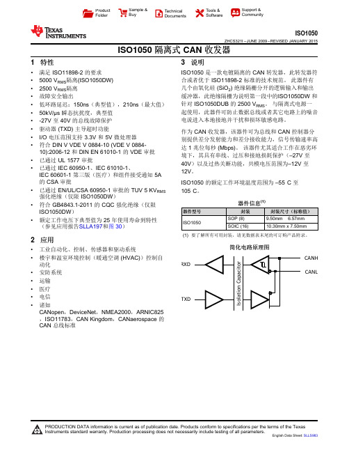
器件型号 ISO1050
器件信息(1)
封装
封装尺寸(标称值)
SOP (8)
9.50mm × 6.57mm
SOIC (16)
10.30mm x 7.50mm
(1) 要了解所有可用封装,请见数据表末尾的可订购产品附录。
简化电路原理图
CANH RXD
CANL
TXD
1பைடு நூலகம்
PRODUCTION DATA information is current as of publication date. Products conform to specifications per the terms of the Texas Instruments standard warranty. Production processing does not necessarily include testing of all parameters.
English Data Sheet: SLLS983
ISO1050
ZHCS321I – JUNE 2009 – REVISED JANUARY 2015
目录
1 特性.......................................................................... 1 2 应用.......................................................................... 1 3 说明.......................................................................... 1 4 修订历史记录 ........................................................... 2 5 Pin Configuration and Functions ......................... 5 6 Specifications......................................................... 6
tja1050中文资料

可以界面设计:Can总线是一个串行通信网络,可以有效地支持分布式控制和实时控制。
它以其高性能和高可靠性而被广泛应用于自动控制领域。
为了提高系统的驱动能力并增加通信距离,飞利浦82C250通常用作CAN控制器与物理总线(即收发器)之间的接口,以增强总线的差分传输能力。
以及CAN控制器的差分接收能力。
为了进一步提高抗干扰能力,经常在CAN控制器和收发器之间设置光电隔离电路。
典型的CAN总线接口电路原理如图1所示接口电路设计中的关键问题1.1光电隔离电路尽管光电隔离电路可以增强系统的抗干扰能力,但也会增加CAN总线有效环路信号的传输延迟时间,从而导致通信速率或距离的降低。
82C250和其他Can收发器具有瞬时抗干扰能力,可减少射频干扰(RFI)并实现热保护。
限流电路还为总线提供了进一步的保护。
因此,如果场传输距离近并且电磁干扰小,则不使用光电隔离来实现最大的通信速率或距离,并且可以简化接口电路。
如果现场环境需要光电隔离,则应选择高速光电隔离装置以减少CAN总线有效环路信号的传输延迟时间。
例如,传输延迟时间6n137短,典型值仅为48 ns,接近TTL电路的传输延迟时间。
1.2电源隔离光电隔离装置两侧使用的电源的Vdd和VCC必须完全隔离,否则光电隔离将失去应有的功能。
电源的隔离可以通过低功率DC / DC电源隔离模块来实现,例如具有5V双隔离输出的低功率DC / DC模块,其总体尺寸为dip-14标准引脚。
1.3上拉电阻图1中的罐收发器82C250的发送数据输入TXD与光耦合器6n137的输出连接。
注意,TXD还必须连接到上拉电阻R3。
一方面,R3确保6n137中的光敏三极管在导通时可以输出低电平,在截止时可以输出高电平。
另一方面,它也是CAN总线的要求。
具体来说,82C250的TXD端子的状态确定高和低罐电压输入/输出端子上的canh和canl的状态(请参见表1)。
Can总线规定,总线在空闲期间应为隐性,即Can网络中节点的默认状态为隐性,这要求TXD 终端的默认状态82c25o为逻辑1(高电平)。
tja1050中文资料

tja1050中文资料集成电路(英语:integrated circuit,缩写作IC),或称微电路(microcircuit)、微芯片(microchip)、晶片/芯片(chip)在电子学中是一种把电路(主要包括半导体设备,也包括被动组件等)小型化的方式,并时常制造在半导体晶圆表面上。
晶体管发明并大量生产之后,各式固态半导体组件如二极管、晶体管等大量使用,取代了真空管在电路中的功能与角色。
到了20世纪中后期半导体制造技术进步,使得集成电路成为可能。
相对于手工组装电路使用个别的分立电子组件,集成电路可以把很大数量的微晶体管集成到一个小芯片,是一个巨大的进步。
集成电路的规模生产能力,可靠性,电路设计的模块化方法确保了快速采用标准化集成电路代替了设计使用离散晶体管。
集成电路对于离散晶体管有两个主要优势:成本和性能。
成本低是由于芯片把所有的组件通过照相平版技术,作为一个单位印刷,而不是在一个时间只制作一个晶体管。
性能高是由于组件快速开关,消耗更低能量,因为组件很小且彼此靠近。
2006年,芯片面积从几平方毫米到350 mm²,每mm²可以达到一百万个晶体管。
第一个集成电路雏形是由杰克·基尔比于1958年完成的,其中包括一个双极性晶体管,三个电阻和一个电容器,相较于现今科技的尺寸来讲,体积相当庞大。
电子显微镜下碳纳米管微计算机芯片体的场效应画面根据一个芯片上集成的微电子器件的数量,集成电路可以分为以下几类:小型集成电路(SSI英文全名为Small Scale Integration):逻辑门10个以下或晶体管100个以下。
中型集成电路(MSI英文全名为Medium Scale Integration):逻辑门11~100个或晶体管101~1k个。
大规模集成电路(LSI英文全名为Large Scale Integration):逻辑门101~1k个或晶体管1,001~10k个。
无缝内衣机纱线张力自整定PID控制器设计

无缝内衣机纱线张力自整定PID控制器设计万中魁;胡旭东;彭来湖【摘要】针对无缝内衣机织造时的纱线张力实时变化和现有控制器抗干扰能力差、纱线张力控制精度低的问题,对纱线张力的采集、直流电机的驱动、数据的传输和纱线张力的恒定进行了研究,提出了一种基于CAN总线通讯和模糊参数自整定PID 方法的控制器.阐述了控制器的硬件电路设计和软件设计,给出了纱线张力检测电路、直流电机驱动电路、CAN总线接口电路和断纱报警电路的工作原理以及CAN总线的通讯方法.重点论述了基于模糊规则的自整定PID控制方法的实现,并利用Simulink仿真对控制器的准确性进行了测试.研究结果表明,该控制器有效解决了纱线张力的非线性时变问题,实现了纱线的恒张力输送,使编织成圈均匀整齐,且系统稳定性高,实时性好.【期刊名称】《机电工程》【年(卷),期】2015(032)012【总页数】5页(P1611-1615)【关键词】恒张力;纱线;CAN总线;自整定PID【作者】万中魁;胡旭东;彭来湖【作者单位】浙江理工大学教育部现代纺织装备技术工程研究中心,浙江杭州310018;浙江理工大学教育部现代纺织装备技术工程研究中心,浙江杭州310018;浙江理工大学教育部现代纺织装备技术工程研究中心,浙江杭州310018【正文语种】中文【中图分类】TH39;TS1830 引言无缝针织内衣机是一种集约化控制的机电一体化针织设备,专门用于编织高档无缝全成形针织内衣产品[1]。
为了保证无缝内衣产品的弹性和舒适度,针织材料多采用高弹性纱线。
弹性纱线输送过程中,张力的变化直接影响编织成圈的均匀和整齐。
所以,实现弹性纱线的恒张力输送,是无缝内衣机准确成圈的关键。
可靠稳定的恒张力输纱控制系统能大大提升无缝内衣机的编织效率和产品质量。
该设计通过对编织成圈过程中纱线张力变化进行研究,提出一种基于CAN 总线通讯和模糊规则自整定PID 方法的控制器,以解决无缝内衣机织造时的纱线张力实时变化和现有控制器抗干扰能力差、纱线张力控制精度低的问题。
1050拉矫机参数
1050拉矫机生产线技术参数及配置一、拉矫机工作原理及情况介绍:我公司制造的拉矫机采用两对弯曲辊组、两个矫直辊组结构。
前后S辊与拉矫主机一体的结构型式,机架两主面采用整张75 mm的热轧钢板,整体刚性好、工作平稳可靠、安装方便、设备精度高、布置紧凑。
设备配备四个弯曲辊组.可以使带钢获得更大的延伸率,为生产出高质量的产品提供了有效保证。
该拉矫机具有液压快速开闭功能.通过回转油缸控制升降平台快速开闭辊系,以防焊缝对拉矫机工作辊造成损坏。
通过电动蜗轮丝杠升降机可实现工作辊压入量的快速调整及准确定位。
配备有矫直横弯组,可以消除带钢弓弯。
在拉矫机出口处设置了矫直带钢纵向弯曲的矫直辊组可有效的去除在长度方向上的弯曲,保证带钢具有最佳的平直度。
我公司拉矫机主要用户为:1999年广东三水南方镀锌板厂;2001年江苏常熟镀锌板厂、山西万邦集团;2004年广东顺德陈村中联不锈钢厂、高明基业、高明泰裕,2005年广东佛山业和、佛山联盈、佛山伟刚、河源向阳、宁波伟伟、河北盛芳华东、福州富源,2006年佛山浩创、邢台博纳、太原赛林、揭阳集润、天津恒兴、福建永大、包头华灵等公司。
二、机组技术性能:1、机组名义宽度:1050mm2、基本规格:材质:普碳钢、镀锌板、不锈钢。
带材宽度:≤1000mm带材厚度:0.15-1.5mm来料带卷内径:φ500mm成品卷内经:φ500mm带卷外经:φ1450mm3、延伸率:0-3%4、机组速度:≤120m/min5、穿带速度:0.3m/s三、机组主要组成单元1、液压横切剪机;2、上卷小车;3、液压四棱锥开卷机;4、带托辊擦料台;5、缝焊机;6、带前后S辊双弯双矫拉伸矫直机;7、液压横切剪机;8、检验平台;9、托辊;10、液压四棱锥卷取机;11、卸卷小车。
四、主要工艺技术参数:1、主机矫直系统:第一、二弯曲辊系:φ30/φ40×1050mm,φ75×180mm×4第一矫平辊系:φ200×1050mm,φ35/φ50×1050mm,φ75×180 mm×4第二矫平辊系:φ200×1050mm,φ60×1050mm,φ75×180 mm×4弯曲辊压下量:0-60 mm矫平辊压下量:0-60 mm系统压下调整方式:电动2、张力辊系统:辊系规格:φ800×1050 mm S型布置矫直段最大张力:80KN1号辊电机:Z4-180-41 55 KW 1500/3000 440V2号辊电机:Z4-200-31 90 KW 1500/2800 440V3号辊电机:Z4-225-11 110 KW 1500/3000 440V4号辊电机:Z4-180-41 55 KW 1500/3000 440V减速机:速比:31.5矫直段最大张力:80KN3、卷取机卷筒规格:φ500×1050 mm(φ470-φ520 mm)卷取张力(最大):14KN卷取电机:Z4-250-31 55 KW 450/1500涨缩形式:液动4、开卷机卷筒规格:φ500×1050 mm(φ470-φ520 mm)开卷张力(最大):14KN开卷电机:Z4-250-31 55 KW 450/1500涨缩形式:液动五、电控系统采用英国欧陆公司590型数字式调速直流电源单独驱动,要具有良好的静态和动态特性,要求延伸率给定并闭环控制,具有延伸率直接显示仪表。
1050a材料标准
1050a材料标准1050A材料标准引言:一、材料用途:1050A铝合金广泛应用于航空航天、汽车、电子、建筑等领域。
在航空航天领域,它被用于制造飞机结构件、燃油箱和座椅框架等。
在汽车领域,1050A铝合金可以用于制造车身、发动机零部件和车轮等。
在电子领域,它可以用于制造电子器件的外壳和散热器等。
此外,1050A铝合金还可用于建筑领域的门窗、幕墙和装饰材料等。
二、化学成分:1050A铝合金的化学成分要求如下:- 铝(Al)含量不低于99.50%;- 铜(Cu)含量不超过0.05%;- 铁(Fe)含量不超过0.40%;- 锰(Mn)含量不超过0.05%;- 硅(Si)含量不超过0.25%;- 锌(Zn)含量不超过0.07%;- 钛(Ti)含量不超过0.03%;- 铬(Cr)含量不超过0.05%。
三、力学性能:1050A铝合金的力学性能要求如下:- 抗拉强度(σb)不低于80MPa;- 屈服强度(σ0.2)不低于30MPa;- 断裂伸长率(δ)不低于25%。
四、工艺要求:在1050A铝合金的加工过程中,需要遵守以下工艺要求:- 熔炼温度:720℃~750℃;- 浇注温度:680℃~700℃;- 铸态合金的热处理温度:200℃~230℃;- 挤压温度:420℃~460℃;- 淬火温度:510℃~530℃。
五、结论:1050A铝合金是一种优良的工业材料,具有广泛的用途和良好的化学成分、力学性能。
在使用该材料时,需要遵守相应的工艺要求,以确保制造出高质量的产品。
希望本文对读者对1050A材料标准有所了解,并对相关行业的从业人员提供参考。
- 1、下载文档前请自行甄别文档内容的完整性,平台不提供额外的编辑、内容补充、找答案等附加服务。
- 2、"仅部分预览"的文档,不可在线预览部分如存在完整性等问题,可反馈申请退款(可完整预览的文档不适用该条件!)。
- 3、如文档侵犯您的权益,请联系客服反馈,我们会尽快为您处理(人工客服工作时间:9:00-18:30)。
TJA1050T/CM,118 中文资料规格参数
反馈错误
参数列表
搜索代替器件
技术参数
电源电压(DC)
4.75 V (min)
封装参数
安装方式
Surface Mount
引脚数
8
封装
SOIC
外形尺寸
封装
SOIC
其他
产品生命周期
Active
包装方式
Cut Tape (CT)
制造应用
车用, 通信与网络, Communications & Networking, Automotive
符合标准
RoHS标准
Compliant
含铅标准
无铅
REACH SVHC标准
No SVHC
海关信息
ECCN代码
EAR99
产品概述
NXP? TJA1050T/CM,118? 总线, CAN, 收发器, CAN, 1, 1, 4.75 V, 5.25 V, SOIC
TJA1050T/CM, 118是一款CAN收发器, 用于控制器局域网(CAN)协议控制器与物理总线之间的连接. 该器件向总线提供差分发送功能, 并向CAN控制器提供差分接收功能. 该产品是在PCA82C250与PCA82C251之后, 第三款Philips高速CAN收发器.
.
完全符合ISO 11898标准
.
高速(高达1 Mbaud)
.
非常低的电磁辐射(EME)
.
差分接收器, 具有宽共模范围, 高电磁抗扰度(EMI) .
一个无电节点, 不会干扰总线
.
传输数据(TXD)主导超时功能
.
静音模式下, 发送器被禁用
.
在车用环境中, 瞬态保护总线引脚
.
输入电平兼容3.3/5V设备
.
热保护
.
短路保护至电池, 与至地面
.
至少可以连接110个节点
TJA1050T/CM,118品牌厂家:NXP(恩智浦),TJA1050T/CM,118渠道分销商:11家,现货库存数量:1009290 PCS,
TJA1050T/CM,118价格参考:?1.651元。
NXP(恩智浦)
TJA1050T/CM,118参数(,封装:SOIC),TJA1050T/CM,118中文资料和引脚图及功能表说明书PDF下载(23页,384KB),您可以在TJA1050T/CM,118CAN芯片规格书Datesheet数据手册中,查到TJA1050T/CM,118引脚图及功能的应用电路图电压和使用方法,TJA1050T/CM,118典型电路教程。
TJA1050T/CM,118可以用什么代替?代换型号如:L9615D013TR、SN65LBC031QD 替代换,TJA1050T/CM,118芯片系列中文手册中包含
TJA1050T/CM,118各引脚定义说明介绍及TJA1050T/CM,118引脚功能图解,用户中文手册TJA1050T/CM,118芯片手册PDF下载(23页,384KB)。
您可在采芯网下载TJA1050T/CM,118产品选型手册,TJA1050T/CM,118产品设计参考手册,TJA1050T/CM,118用户编程技术手册,TJA1050T/CM,118开发手册(1个文件)。
