繁易触摸屏资料
4007ES色彩触摸屏液晶显示屏说明书

© 2015 Tyco Fire Protection Products. All rights reserved. Specifications and other information shown were current as of publication and are subject to change without notice.579-1172Rev. AIntroductionThe Color Touchscreen LCD Annunciator for 4007ES panels* provides remote annunciation of the Fire Alarm Control Panel (FACP) status. Visual status is provided by the touchscreen and by the LEDs. Audible annunciation is provided through a piezo sounder. Access to Annunciator switch functions can be enabled or locked using the keyswitch. A maximum of six color touchscreen annunciators can be installed on a 4007ES panel.* 4007ES panels include the 4007ES hybrid panels and the 4007ES panels with IDNAC notification. From this point on, they will be referred to as 4007ES.CompatibilityThe 4007ES panel needs to be at revision 3.02.07 or higher to support the Color Touchscreen LCD Annunciator.The following annunciators, boxes, and brackets are compatible with 4007ES panels:Reference DocumentsRefer to the following documents for more information on how to program and use the remote annunciator.Cautions and WarningsREAD AND SAVE THESE INSTRUCTIONS - Follow the instructions in this installation manual. These instructionsmust be followed to avoid damage to this product and associated equipment. Product operation and reliability depend upon proper installation.DO NOT INSTALL ANY SIMPLEX® PRODUCT THAT APPEARS DAMAGED - Upon unpacking your Simplexproduct, inspect the contents of the carton for shipping damage. If damage is apparent, immediately file a claim with the car-rier and notify an authorized Simplex product supplier.ELECTRICAL HAZARD - Disconnect electrical field power when making any internal adjustments or repairs. All repairsshould be performed by a representative or authorized agent of your local Simplex product supplier.FCC RULES AND REGULATIONS – PART 15 - This equipment has been tested and found to comply with the limits for a Class A digital devicepursuant to Part 15 of the FCC Rules. These limits are designed to provide reasonable protection against harmful interference when the equipment is operated in a commercial environment. This equipment generates, uses, and can radiate radio frequency energy and, if not installed and used in accor-dance with the instruction manual, may cause harmful interference to radio communications. Operation of this equipment in a residential area is likely tocause harmful interference in which case the user will be required to correct the interference at his own expense.Part Number Description4606-9202Color Touchscreen LCD Annunciator, Red 4606-9205Color Touchscreen LCD Annunciator, Platinum2975-9461Color Touchscreen LCD Annunciator, Surface Mount Box, Red 2975-9462Color Touchscreen LCD Annunciator, Surface Mount Box, Platinum 2975-9463Color Touchscreen LCD Annunciator, Retrofit, Semi-flush bracket, Red 2975-9464Color Touchscreen LCD Annunciator, Retrofit, Semi-flush bracket, PlatinumIn thispublicationReference Documents ................................1Wire Length Tables .....................................5Module Overview ........................................2Communication Wiring Length Tables ........6General Mounting Information ....................3Address Setting ...........................................6General Wiring Guidelines ..........................3Mounting Instructions ..................................8Specific Wiring Guidelines ..........................3Verification Procedure .................................8Wiring . (4)Remote Annunciator Specifications (9)Document Number Title579-11654007ES Operator’s manual 579-11674007ES Programmer’s manualDocument: Installation Manual Part: Color Touchscreen LCD Annunciator Product:4007ES PanelsModule Refer to Figure 1 for the remote annunciator front view and to Figure 2 for the back layout.Figure 1. Remote Annunciator Front ViewPower LEDSupervisory LEDPriority 2 LED Fire LED Alarm Silenced LED Trouble LEDONOFF1 2 3 4 5 6 7 8 USB PortSerial Service PortReset SwitchAddress SwitchGeneral Mounting Information Flush-mount annunciators•In masonry walls or plasterboard walls, use a RACO 944 identify as a 5-gang box (2½ in /64 mm deep) box or its equivalent.Surface mount annunciators•Use a 2975-9461 box (2½ in/64 mm deep), red.•Use a 2975-9462 box (2½ in/64 mm deep), platinum.Semi-flush-mount annunciatorsFor mounting to an existing six-gang box, masonry box, 2975-9206 box, or 2975-9217 box:•Use bracket 2975-9463 (1¾ in/44.5 mm), red.•Use bracket 2975-9464 (1¾ in/44.5 mm), platinum.General Wiring Guidelines •All wiring must be copper conductors only.•Wire lengths in excess of the maximum lengths (see Table 2 through Table 5) are not permitted.•If shielding is used:-Metallic continuity of the shield must be maintained throughout the entire length of cable.-The entire length of the cable must have a resistance greater than 1 X 10⁶ ohms to Earth ground.-The shield must connect to a SHIELD terminal at each annunciator and must beterminated only at the main panel.•Underground wiring must be free of water.•Wires must not be run through elevator shafts.•Wire runs in plenums must be in conduit unless rated for plenum use.•Splicing is permitted provided that:-All such connections are soldered (rosin-core solder), crimped in metal sleeves, orencapsulated with an epoxy resin;-When solder or crimped metal sleeves are used, the junction is insulated with a highgrade electrical tape as sound as the original insulating jacket;-The shield’s continuity is maintained throughout the cable’s length.•Only system wiring can share the same conduit.Specific Wiring Guidelines •24V power wiring must be power limited and communication wiring is supervised and power limited.•The Remote Annunciator cannot be used with wiring that goes outside the building (above or below ground), unless overvoltage suppression is provided at both ends for both thecommunication and the power wiring. Communication and power wiring must meet the following requirements:1. Simplex Model 2081-9044 overvoltage protectors (200 mA or less):-There are no restrictions on wire routing, however, the maximum wire length is 2500 feet.2. Simplex Model 2081-9027 (200 mA maximum) or Model 2081-9028 (5-amp maximum)isolated loop circuits protectors:-For underground wiring, select the appropriate isolated loop circuit protector. The circuit wiring must be run in a separate parallel wiring trough, separated from any commercial power distribution wiring.-For overhead wiring, select the appropriate isolated loop circuit protector. The wiring is limited to one contiguous property and the total wire length must not exceed 2500 feet.The circuit wiring must be run on separate poles, separated from any poles supportingcommercial power distribution wiring. The circuit wiring must be run in parallel withdirect relation to the commercial power distribution. The separation is a minimum distance (whichever is greater) of 100 feet, or the maximum span between any two adjacent poles of either the system’s circuit or the commercial power distribution circuit.•For maximum wire lengths with or without circuit protectors, see Table 2 through Table 5.•If the interconnected control unit is not used to provide operating power to the annunciator, a regulated power-limited, UL-listed 24VDC power supply for fire protective signaling must be used.•12-18 AWG twisted pair wiring is required for RUI communications.•In accordance with NFPA 70, Article 250, a dedicated Earth ground connection must be provided to the back box.WiringNote: To prevent Electrostatic Discharge (ESD), use a wrist strap assembly that connects toground. Ensure power is OFF before installing or servicing the annunciator.To properly install the remote annunciator:1. Terminate the annunciator’s RUI communication and power lines (Figure 3).2. Connect the ground harness (see Figure 2) to the metal back box’s Earth ground.Figure 3. Terminating the COMM and Power LineTB1-1: 24V IN from FACP Power Supply orPrevious AnnunciatorTB1-2: 24V OUT to Next AnnunciatorTB1-3: 24C IN from FACP Power Supply or Previous AnnunciatorTB1-4: 24C OUT to Next Annunciator TB1-5: +COMM IN+RUI communications from FACP or Previ-ous AnnunciatorTB1-6: +COMM OUT+RUI communications to Next Annunciator TB1-7: -COMM IN-RUI communications from FACP or Previous Annunciator TB1-8: -RUI communications to Next AnnunciatorTB1-9: SHIELD INTB1-10: SHIELD OUTWire Length TablesTable 2 and Table 3 show the maximum wire lengths possible for the power wiring. Table 4 and Table 5 shows the maximum wire lengths for the communication wiring.•When using multiple annunciators and runs, the total of all runs must not exceed 10,000 ft. (304.8 m) (including T-Taps).•Four 2081-9044 Overvoltage Protectors or four 2081-9028 Isolated Loop Circuit Protectors are the maximum number permitted on any single communication loop.Power Wiring Length TablesTable 2. Wire Length with 2081-9044 Overvoltage ProtectorsTable 3. Without Transient Suppression (or with 2081-9028 Isolated Loop Circuit Protectors)Total Current (Amps)12 AWG (3.309 mm²)14 AWG (2.801 mm²)16 AWG (1.309 mm²)18 AWG (0.823 mm²)0.100 2,500 ft. (762 m)2,500 ft.(762 m)2,371 ft. (722.68 m)1,409 ft. (429.46 m) 0.2002,500 ft. (762 m)1,782 ft. (543.15 m)889 ft. (270.96 m)705 ft. (214.88 m)Total Current (Amps)12 AWG (3.309 mm²)14 AWG (2.801 mm²)16 AWG (1.309 mm²)18 AWG (0.823 mm²)0.1002,500 ft. (762 m)2,500 ft.(762 m)2,500 ft.(762 m)2,349 ft.(715.97 m)0.2002,500 ft. (762 m)2,500 ft.(762 m)1,482 ft.(451.71 m)1,175 ft.(358.14 m)0.3002,500 ft. (762 m)1,980 ft.(603.5 m)988 ft.(301.14 m)783 ft.(238.65 m)0.4002,361 ft. (719.63 m)1,485 ft.(452.62 m)741 ft.(225.85 m)587 ft.(178.91 m)0.5001,889 ft. (575.76 m)1,188 ft.(362.1 m)593 ft.(180.74 m)470 ft.(143.25 m)0.6001,574 ft. (479,75 m)990 ft.(301.75 m)494 ft.(150.57 m)392 ft.(119.48 m)0.7001,349 ft. (411.17 m)849 ft.(258.77 m)423 ft.(128.93 m)336 ft.(102.41 m)0.8001,181 ft. (359.96 m)743 ft.(226.46 m)371 ft.(113.08 m)294 ft.(89.61 m)0.9001,049 ft. (319.73 m)660 ft.(201.16 m)329 ft.(100.27 m)261 ft.(79.55 m)1.000944 ft. (287.73 m)594 ft.(181 m)296 ft.(90.22 m)235 ft.(71.62 m)1.100859 ft. (261.82 m)540 ft.(164.59 m)269 ft.(81.99 m)214 ft.(65.22 m)1.200787 ft. (239.87 m)495 ft.(150.87 m)247 ft.(75.28 m)196 ft.(59.74 m)With 2081-9027 Isolated Loop Circuit Protectors0.1002,500 ft.(762 m)2,500 ft.(762 m)2,371 ft. 2,371 ft. (722,68 m)1,409 ft.(429.46 m)0.2002,500 ft.(762 m)1,782 ft. (543,15 m)889 ft.(270.96 m)705 ft.(214.88 m)Communication Wiring Length TablesTable 4. With 2081-9044 Overvoltage ProtectorsTable 5. Without Transient Suppression (or with 2081-9028 Isolated Loop Circuit Protectors)Address Setting Switch SW2 is a bank of eight dip switches. From left to right (see Figure 5) these switches aredesignated as SW2-1 through SW2-8. The function of these switches is as follows:•SW2-1. This switch enables communication between the card and the FACP CPU. Set this switch to ON for normal operation.•SW2-2 through SW2-8. These switches set the card addressfor the FACP. Refer to Table 6 for a complete list of the switch settings for all of the possible card addresses. Each card mustbe set to the address assigned in the FACP programmer.Figure 5. DIP Switch SW212 AWG (3.309 mm²)14 AWG (2.801 mm²)16 AWG (1.309 mm²)18 AWG (0.823 mm²)2,500 ft. (762 m)2,500 ft. (762 m)2,450 ft.(746.76 m)1,650 ft.(502.92 m)12 AWG (3.309 mm²)14 AWG (2.801 mm²)16 AWG (1.309 mm²)18 AWG (0.823 mm²)2,500 ft. (762 m)2,500 ft. (762 m)2,500 ft. (762 m)2,349 ft.(715.97 m)With 2081-9027 Isolated Loop Circuit Protectors2,500 ft. (762 m)2,500 ft. (762 m)2,450 ft.(746.76 m)1,650 ft.(502.92 m)ON OFF (DIP Switch shown is set at address 31)12345678Most Significant BitLeast Significant BitAddress Setting Table 6.Address ChartAddress SW 2-2SW 2-3SW 2-4SW 2-5SW 2-6SW 2-7SW 2-8Address SW 2-2SW 2-3SW 2-4SW 2-5SW 2-6SW 2-7SW 2-8 1ON ON ON ON ON ON OFF61ON OFF OFF OFF OFF ON OFF 2ON ON ON ON ON OFF ON62ON OFF OFF OFF OFF OFF ON 3ON ON ON ON ON OFF OFF63ON OFF OFF OFF OFF OFF OFF 4ON ON ON ON OFF ON ON64OFF ON ON ON ON ON ON 5ON ON ON ON OFF ON OFF65OFF ON ON ON ON ON OFF 6ON ON ON ON OFF OFF ON66OFF ON ON ON ON OFF ON 7ON ON ON ON OFF OFF OFF67OFF ON ON ON ON OFF OFF 8ON ON ON OFF ON ON ON68OFF ON ON ON OFF ON ON 9ON ON ON OFF ON ON OFF69OFF ON ON ON OFF ON OFF 10ON ON ON OFF ON OFF ON70OFF ON ON ON OFF OFF ON 11ON ON ON OFF ON OFF OFF71OFF ON ON ON OFF OFF OFF 12ON ON ON OFF OFF ON ON72OFF ON ON OFF ON ON ON 13ON ON ON OFF OFF ON OFF73OFF ON ON OFF ON ON OFF 14ON ON ON OFF OFF OFF ON74OFF ON ON OFF ON OFF ON 15ON ON ON OFF OFF OFF OFF75OFF ON ON OFF ON OFF OFF 16ON ON OFF ON ON ON ON76OFF ON ON OFF OFF ON ON 17ON ON OFF ON ON ON OFF77OFF ON ON OFF OFF ON OFF 18ON ON OFF ON ON OFF ON78OFF ON ON OFF OFF OFF ON 19ON ON OFF ON ON OFF OFF79OFF ON ON OFF OFF OFF OFF 20ON ON OFF ON OFF ON ON80OFF ON OFF ON ON ON ON 21ON ON OFF ON OFF ON OFF81OFF ON OFF ON ON ON OFF 22ON ON OFF ON OFF OFF ON82OFF ON OFF ON ON OFF ON 23ON ON OFF ON OFF OFF OFF83OFF ON OFF ON ON OFF OFF 24ON ON OFF OFF ON ON ON84OFF ON OFF ON OFF ON ON 25ON ON OFF OFF ON ON OFF85OFF ON OFF ON OFF ON OFF 26ON ON OFF OFF ON OFF ON86OFF ON OFF ON OFF OFF ON 27ON ON OFF OFF ON OFF OFF87OFF ON OFF ON OFF OFF OFF 28ON ON OFF OFF OFF ON ON88OFF ON OFF OFF ON ON ON 29ON ON OFF OFF OFF ON OFF89OFF ON OFF OFF ON ON OFF 30ON ON OFF OFF OFF OFF ON90OFF ON OFF OFF ON OFF ON 31ON ON OFF OFF OFF OFF OFF91OFF ON OFF OFF ON OFF OFF 32ON OFF ON ON ON ON ON92OFF ON OFF OFF OFF ON ON 33ON OFF ON ON ON ON OFF93OFF ON OFF OFF OFF ON OFF 34ON OFF ON ON ON OFF ON94OFF ON OFF OFF OFF OFF ON 35ON OFF ON ON ON OFF OFF95OFF ON OFF OFF OFF OFF OFF 36ON OFF ON ON OFF ON ON96OFF OFF ON ON ON ON ON 37ON OFF ON ON OFF ON OFF97OFF OFF ON ON ON ON OFF 38ON OFF ON ON OFF OFF ON98OFF OFF ON ON ON OFF ON 39ON OFF ON ON OFF OFF OFF99OFF OFF ON ON ON OFF OFF 40ON OFF ON OFF ON ON ON100OFF OFF ON ON OFF ON ON 41ON OFF ON OFF ON ON OFF101OFF OFF ON ON OFF ON OFF 42ON OFF ON OFF ON OFF ON102OFF OFF ON ON OFF OFF ON 43ON OFF ON OFF ON OFF OFF103OFF OFF ON ON OFF OFF OFF 44ON OFF ON OFF OFF ON ON104OFF OFF ON OFF ON ON ON 45ON OFF ON OFF OFF ON OFF105OFF OFF ON OFF ON ON OFF 46ON OFF ON OFF OFF OFF ON106OFF OFF ON OFF ON OFF ON 47ON OFF ON OFF OFF OFF OFF107OFF OFF ON OFF ON OFF OFF 48ON OFF OFF ON ON ON ON108OFF OFF ON OFF OFF ON ON 49ON OFF OFF ON ON ON OFF109OFF OFF ON OFF OFF ON OFF 50ON OFF OFF ON ON OFF ON110OFF OFF ON OFF OFF OFF ON 51ON OFF OFF ON ON OFF OFF111OFF OFF ON OFF OFF OFF OFF 52ON OFF OFF ON OFF ON ON112OFF OFF OFF ON ON ON ON 53ON OFF OFF ON OFF ON OFF113OFF OFF OFF ON ON ON OFF 54ON OFF OFF ON OFF OFF ON114OFF OFF OFF ON ON OFF ON 55ON OFF OFF ON OFF OFF OFF115OFF OFF OFF ON ON OFF OFF 56ON OFF OFF OFF ON ON ON116OFF OFF OFF ON OFF ON ON 57ON OFF OFF OFF ON ON OFF117OFF OFF OFF ON OFF ON OFF 58ON OFF OFF OFF ON OFF ON118OFF OFF OFF ON OFF OFF ON 59ON OFF OFF OFF ON OFF OFF119OFF OFF OFF ON OFF OFF OFF 60ON OFF OFF OFF OFF ON ONMounting Instructions 1. Using the four provided screws, mount the annunciator in its back box (see Figure 6 for semi-flush mounting and Figure 7 for surface mounting).2. Label the separate user-defined labels with the appropriate designation.3. Carefully pull the top of the label pocket forward and insert the user-defined labels.4. Gently push on the trim plate to snap it in place, over the annunciator.Remote Annunciator SpecificationsTable 7. Remote Annunciator SpecificationsOperating Conditions:Operating Temperature Range32o F - 120o F (0o C-49o C)Operating Humidity Range Up to 93% relative humidity at 100o F (38o C), non-condensing. Power Supply24VDC Nominal/18VDC minimum at power input terminals ofannunciator to allow for wiring losses.Maximum Current Draw Backlight ON at 24VDC: 70mABacklight dimmed at 24 VDC: 45mA579-1172。
Touch-Panel技术简介

2 计算X坐标,在LL电极施加驱动电压Vdrive, UR电极接地, 活动电极做为引 出端测量得到接触点的电压。
2021/8/2
19
五线触摸屏的工作原理与四线电阻式不同的是:五线式的X和Y方向上的驱动 电压均由下线路的ITO层产生,而上线路层仅仅扮演侦测电压探针的作用。即 便上线路薄膜层被刮伤或损坏,触摸屏也能正常工作,所以五线电阻式的使 用寿命远比四线式的长。
2021/8/2
31
Iphone的触摸屏采用的是Multi-Touch All-Point的检测方式。
Multi-Touch All-Point触摸屏包括了一 排的驱动线和一排的检测线。
2021/8/2
32
iPhone的处理器和软件将准确地分析并执行从触摸屏传来的信息。电容 发往iPhone处理器的是关于最原始的触摸位置的数据。处理器通过指令 使存储在iPhone中的软件去解析这些原始数据。
2021/8/2
25
在电容式触摸屏问世后多年,触摸屏都只能每次响应一个触点。一旦我 们操控超过一个触点,电容式触摸屏就会因为无法定位而让光标错乱。
新式电容触摸屏: 新式电容触摸屏是从电容式触摸按键经过插值算法引
申出来的一种触摸屏检测方法,可以支持多点触摸。如 Iphone使用的就是典型的电容触摸感应实现多点触摸。
五线触摸屏主要是考虑电极抽头引线和驱动电极的电路的寄生电阻,这 部分电阻并不包含在ITO电阻之内,而且受环境温度影响阻值波动,很可能影 响计算的正确性。
2021/8/2
20
·在Y+电极施加驱动电压Vdrive, Y-电极接地,分别测出Y+ sense和Ysense 的电压,分别记为VYMAX和VYMIN, ·在X+电极施加驱动电压Vdrive, X-电极接地,分别测出X+ sense和Xsense 的电压,分别记为VXMAX和VXMIN 。
Eaton PXBCM 6英寸彩色触屏显示仪用户手册说明书

PXBCM Meter Color T ouchscreen Display User Manual2Instruction Booklet IB150007ENEffective August 2015PXBCM Meter Color T ouchscreenDisplay User ManualEATON 1 IntroductionThe Eaton PXBCM Meter 6” Color Touchscreen Display (PXBCM-DISP-6 ) is pre-programmed to communicate with Eaton PXBCM-MB Meters. The programming allows access to branch-circuit-monitor data and meters through the PXBCM meter base. The built-in navi-gation functions are simple and convenient, allowing easy navigation between screens. The display has been designed to display overall system information for up to 25 configured virtual meters, 100 chan-nel data meters, and alarms.2 InstallationFor installation and connection information, please refer to “PXBCM Meter Color Touchscreen Display Quick Start Guide” (Eaton Pub. #TD150016EN).3 Using the Touchscreen3.1 Basic NavigationBasic navigation between the screens is accomplished by touching labeled tabs, category areas, buttons or other available selections. In addition, unused areas of the screen can be used to navigate back to the home screen.The home screen provides access to Meter Base (MB) information, Meter Module (MMP1-MMP4) information, Virtual Meters, Channel Data, or Alarms. Touching a tab, category, or information button will take the user to the selected screen (see Figure 1).Figure 1. Navigating from the Home Screen to Virtual Meters, Channel Data, or Alarms Screens.Touching the information button on the MB row will take the user to the screen with Meter Base information (see Figure 2).Figure 2. Meter Base Information.As with many of the screens, the header contains several navigation buttons. Touching the “Back” arrow will return the user to the previ-ous level in the hierarchy, in this case, the home screen. Touching the “Next” arrow will take the user to the next associated screen, MMP1 information in this case. Touching the “Previous” arrow will take the user to the previous associated screen, MMP4 information in this case.Touching the information button for one of the Meter Modules(MMP1-MM4) will take the user to the appropriate screen with infor-mation for the selected Meter Module (see Figure 3).Figure 3. Meter Module Information.BackPreviousNextBackNextPreviousVirtual Meters Channel Data Alarms3Instruction Booklet IB150007ENEffective August 2015PXBCM Meter Color T ouchscreen Display User Manual EATON 3.2 Meters T abTouching the Meters tab will take the user to the list of configured Main and Virtual Meters (see Figure 4). There are up to 25 virtual meters (7 on each of the first three pages and 4 on the fourth page).Figure 4. Main and List of Virtual Meters.Each Virtual Meter or Main has a couple screens containing detailed data for the selected meter (see Figure 5).Figure 5. Main andVirtual Meter Data.3.3 Channel Data T abTouching the Channel Data Tab will take the user to a CategorySelection screen (see Figure 6). Once there, the user will be able to select one of nine categories.•The Voltage Pairing category identifies the current channel name and associated voltage for each current channel.•The Voltage category displays the three line-to-line voltages and three line-to-neutral voltages.•The Amps/Max Amps category displays the present RMS amps and largest recorded amps for each channel.•The Fwd./Rev. Energy category displays the accumulated Forward kWh and Reverse kWh for each channel.•The Watts/Max. Watts category displays the present RMS watts and largest recorded watts for each channel.•The VA/Max.VA category displays the present RMS VA and largest recorded VA for each channel.•The Amp Demand/Peak category displays the most recently cal-culated Amp Demand and largest recorded Amp Demand for each channel.•The Fwd./Rev. Demand category displays the most recently calcu-lated Forward Watt Demand and Reverse Watt Demand for each channel.•The Power Factor category displays the apparent power factor for each channel.4Instruction Booklet IB150007ENEffective August 2015PXBCM Meter Color T ouchscreenDisplay User ManualEATON Figure 6. Channel Data Selection Screen.Touching a category will take the user to the channels 1-7 data for the selected category and the most recently selected MMP . From within the Channel Data screens, the “Previous” and “Next” arrows navigate to adjacent Meter Modules. For example, from MMP1, “Previous” navigates to MMP4 while “Next” navigates to MMP2. Also within the Channel Data screens, the “Up” and “Down” arrows navigate through pages of channel data, specifically 1-7 on the first page, 8-15 on the second page, 16-21 on the third page, and AX1-AX4 on the fourth page (see Figure 7).Figure 7. Channel Data Screen.3.4 Alarm T abTouching the Alarms tab will take the user to an overview of the alarms (see Figure 8). Displayed are the number of Latched Current Alarms and Latched Voltage Alarms for each MMP1, MMP2, MMP3, and MMP4, which act as buttons to display additional alarm details (see Figure 9).Figure 8. Alarms Summary Screen.5Instruction Booklet IB150007ENEffective August 2015PXBCM Meter Color T ouchscreen Display User Manual EATON Figure 9. Latched Alarms.Touching MMP1, MMP2, MMP3, or MMP4 on Alarm Counter rows will take the user to screens with further alarm details. The Current Alarm Counters include columns for “Low-Low” (i.e. very low), “Low”, “High”, and “High-High” (i.e. very high). Meanwhile, the Voltage Alarm Counter include columns for “Low” and “High” (see Figure 10).Figure 10. Current Alarm Counters andVoltage Alarm Counters.6Instruction Booklet IB150007ENEffective August 2015PXBCM Meter Color T ouchscreenDisplay User ManualEATON Notes:7Instruction Booklet IB150007ENEffective August 2015PXBCM Meter Color T ouchscreen Display User Manual EATON Notes:EatonElectrical Sector1000 Eaton Boulevard Cleveland, OH 44122United States877-ETN-CARE (877-386-2273) © 2015 EatonAll Rights ReservedPrinted in USAPublication No. IB150007EN / TBG001240 August 2015Eaton is a registered trademark.All other trademarks are property of their respective owners.Instruction Booklet IB150007EN Effective August 2015 PXBCM Meter Color T ouchscreenDisplay User ManualThe information, recommendations, descriptions, and safety nota-tions in this document are based on Eaton’s experience and judg-ment. This instructional literature is published solely for information purposes and should not be considered all-inclusive. If further infor-mation is required, you should consult an authorized Eaton sales representative.The sale of the product shown in this literature is subject to the terms and conditions outlined in appropriate Eaton selling policies or other contractual agreement between the parties. This literature is not intended to and does not enlarge or add to any such contract. The sole source governing the rights and remedies of any purchaser of this equipment is the contract between the purchaser and Eaton. NO WARRANTIES, EXPRESSED OR IMPLIED, INCLUDING WARRANTIES OF FITNESS FOR A PARTICULAR PURPOSE OR MERCHANTABILITY, OR WARRANTIES ARISING FROM COURSE OF DEALING OR USAGE OF TRADE, ARE MADE REGARDING THE INFORMATION, RECOMMENDATIONS, AND DESCRIPTIONS CONTAINED HEREIN.In no event will Eaton be responsible to the purchaser or user in contract, in tort (including negligence), strict liability or otherwise for any special, indirect, incidental or consequential damage or loss whatsoever, including but not limited to damage or loss of use of equipment, plant or power system, cost of capital, loss of power, additional expenses in the use of existing power facilities, or claims against the purchaser or user by its customers resulting from the use of the information, recommendations and description contained herein.The information contained in this manual is subject to change without notice.。
4寸TFT触摸屏指南书说明书
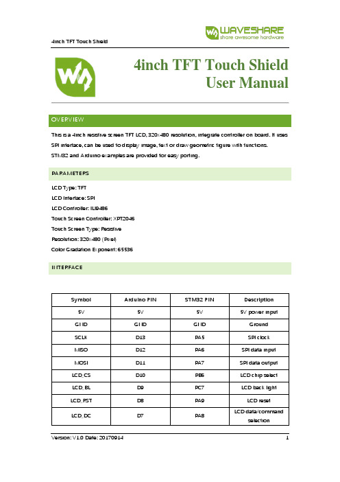
4inch TFT Touch ShieldUser ManualOVERVIEWThis is a 4inch resistive screen TFT LCD, 320x480 resolution, integrate controller on board. It uses SPI interface, can be used to display image, text or draw geometric figure with functions.STM32 and Arduino examples are provided for easy porting.PARAMETERSLCD Type: TFTLCD Interface: SPILCD Controller: ILI9486Touch Screen Controller: XPT2046Touch Screen Type: ResistiveResolution: 320x480 (Pixel)Color Gradation Exponent: 65536INTERFACESymbol Arduino PIN STM32 PIN Description 5V 5V 5V 5V power inputGND GND GND GroundSCLK D13 PA5 SPI clockMISO D12 PA6 SPI data inputMOSI D11 PA7 SPI data outputLCD_CS D10 PB6 LCD chip selectLCD_BL D9 PC7 LCD back lightLCD_RST D8 PA9 LCD resetLCD_DC D7 PA8 LCD data/commandselectionHOW TO USEHARDWARE CONFIGURATION•If there is ICSP interface on Arduino board, set the SPI Config switch onto ICSP position.(default)•If Arduino board has no ICSP interface, set the SPI Config switch onto the position that SCLK\D13, MISO\D12, MOSI\D11EXAMPLESWe provide Arduino UNO examples and XNUCLEO-F103RB examples for this screen.ARDUINO EXAMPLES1.Download the examples: 4inch TFT Touch Shield code.7z, and copy the libraries which are inArduino\lib folder of examples to the libraries folder which is under the installation directory of Arduino IDE.2.Before running the LCD_ShowBMP code, copy the pictures which is in the PIC folder to SDcard.3.Open the LCD_ShowBMP project with Arduino IDE, download to Arduino board.4.The Touch code use four sets of calibration values, could support painting operation in fourdirections. There are five colors which could be selected on the right. The size of paintbrush is 9 pixels by default. Users can also click the AD on screen to calibrate:Please use the stylus click the cross on the screen. The cross will always move until thescreen adjustment is completed.5.Following the prompt, click the red sign “+” one by one to finish the calibration.STM32 EXAMPLES1.Before running the code that display image. copy the pictures which is in the PIC folder toSD card. Then insert the LCD to NUCLEO or XNUCLEO board.2.Open the project with MDK, download to the NUCLEO or XNUCLEO development board.3.The LCD will first show some common functions: Draw dots, draw dotted line and solid line,rectangle, filled rectangle, circle and solid circle. Every figure keeps for 3s. You can change the size of dot, the width of lines and the size of the circles.4.The Touch code use four sets of calibration values, could support painting operation in fourdirections. There are five colors which could be selected on the right. The size of paintbrush is 9 pixels by default. Users can also click the AD on screen to calibrate:Please use the stylus click the cross on the screen. The cross will always move until thescreen adjustment is completed.5.Following the prompt, click the red “+” one by one to finish the calibration.Note:Image: 320x480, 24bit, bmp.SD card: FAT。
触摸屏基本原理及应用

Panel分類 Touch Panel分類
主要觸控技術比較
表面聲波 清晰度 反光性 透光率 色彩失真 解析度 壓力軸回應 漂移 防刮擦 野蠻使用 反應速度 材料 多點觸摸 光干擾 電磁場干擾 防塵 壽命 安裝風險 市場反修率 外觀 現場維護 很好 很少 92%(極限) 4096*4096 有 非常好且不怕硬物 不怕 10ms 純玻璃 智能判斷 沒有此問題 沒有此問題 不怕 >>5千萬次 半永久性 不易碎 0 不影響 不需要 電容式 字元圖像模糊 嚴重 85% 有 1024*1024 有 一般,怕硬物敲擊 一般 15-24ms 四層複合膜 中心點 沒有此問題 有 不怕 2千萬次 易碎 21% 不影響 需經常校準 紅外式 一般 100% 40*32 外框易碎 50-300ms 透光外殼 左上角 不能超範圍 沒有此問題 不能擋住透光 部分 太多感測器 損壞概率大 易摔碎外殼 40% 影響外觀 清潔外殼 五線電阻 較好 有 75% 4096*4096 一般,怕銳器 好,但怕銳器 10ms 鍍於玻璃 中心點 沒有此問題 沒有此問題 不怕 3千5百萬次 不易碎 5% 不影響 不需要 四線電阻 字元圖像模糊 較少 60%左右 有 1024*1024 主要缺陷 差 10-20ms 鍍於有機玻璃 中心點 沒有此問題 沒有此問題 不怕 1百萬次 易損壞ITO 30% 不平整 不需要
5、七線式電阻觸摸屏 、
七線觸摸屏實現方法除在左上角和右下角各增加一根線之外,與五線觸摸屏相同.執行 螢幕測量時,將左上角的一根線連到VREF,另一根線接SAR ADC的正參考端.同時,右下角的 一根線接0V,另一根線連接SAR ADC的負參考端.導電層仍用來測量分壓器的電壓.
ICP DAS TPM-4100 TP-4100触摸屏使用手册说明书

TPM-4100/TP-4100/TPM-6 150/TP-6150/TP-2070觸控螢幕使用手冊⑥WarrantyAll products manufactured by ICP DAS are under warranty regarding defective materials for a period of one year, beginning from the date of delivery to the original purchaser.⑥WarningICP DAS assumes no liability for any damage resulting from the use of this product. ICP DAS reserves the right to change this manual at any time without notice. The information furnished by ICP DAS is believed to be accurate and reliable. However, no responsibility is assumed by ICP DAS for its use, nor for any infringements of patents or other rights of third parties resulting from its use.⑥CopyrightCopyright © 2012 by ICP DAS Co., Ltd. All rights are reserved.⑥TrademarksNames are used for identification purposes only and may be registered trademarks of their respective companies.Contact usIf you encounter any problems, please feel free to contact us.You can rely on ICPDAS for a prompt quick response.Email:******************Table of ContentsTable of Contents (3)1. 介紹 (5)1.1. 特色 (7)1.2. 規格 (8)1.3. 尺寸 (11)1.4. I/O 介面 (19)1.5. 附贈CD (22)1.6. 系統設置 (23)1.6.1. 系統參數設定 (23)1.6.2. 觸控螢幕的安裝 (27)2. 觸控驅動程式的設置 (29)2.1. Windows CE 5.0 (30)2.1.1. USB觸控驅動程式 (31)2.1.1.1. WinPAC-8000 and WinPAC-5000的程式安裝322.1.1.2. WinPAC-8000 and WinPAC-5000的程式設定342.1.1.3. WinPAC-8000 and WinPAC-5000的程式卸載362.1.1.4. 其它Windows CE5.0裝置 (37)2.1.2. 串列(Serial)觸控驅動程式 (38)2.1.2.1. WinPAC-8000 and WinPAC-5000的程式安裝392.1.2.2. WinPAC-8000 and WinPAC-5000的程式設定412.1.2.3. WinPAC-8000 and WinPAC-5000的程式卸載432.1.2.4. 其它Windows CE5.0裝置 (44)2.2. Windows CE 6.0 (45)2.2.1. USB觸控驅動程式 (46)2.2.1.1. XP-8000-CE6的程式安裝 (47)2.2.1.2. XP-8000-CE6的程式設定 (49)2.2.1.3. XP-8000-CE6的程式卸載 (51)2.2.1.4. 其它Windows CE6.0裝置 (53)2.2.2. 串列(Serial)觸控驅動程式 (54)2.2.2.1. XP-8000-CE6的程式安裝 (55)2.2.2.2. XP-8000-CE6的程式設定 (58)2.2.2.3. XP-8000-CE6的程式卸載 (60)2.2.2.4. 其它Windows CE 6.0裝置 (62)2.3. Windows XP Embedded (63)2.3.1. 通用型的觸控驅動程式 (63)2.3.1.1. XP-8000的程式安裝 (64)2.3.1.2. XP-8000的程式設定 (70)2.3.1.3. XP-8000的程式卸載 (74)2.3.1.4. 其它Windows XP Embedded裝置762.4. Windows XP/7 (77)2.4.1. 通用型的觸控驅動程式 (77)2.4.1.1. 安裝 (78)2.4.1.2. 設定 (82)2.4.1.3. 卸載 (84)Appendix A. Revision History (86)1. 介紹TPM-4100/TP-4100/TPM-6150/TP-6150/TP-2070的概述和元件的介紹.TPM-4100/TP-4100/TPM-6150/TP-6150/TP-2070觸控螢幕配備有標準TFT LCD螢幕,有堅固的鋁外殼和廣泛的操作溫度範圍. 我們也保證TPM-4100/TP-4100/ TPM-6150/TP-6150/TP-2070可以被整合到ICP DAS PAC控制系統中使用,例如控制器WP-8000系列和XP-8000系列。
繁易触摸屏资料PPT课件
,直接控制加热部件 • 高可靠性的工业设计
8
医疗设备
• 手术室专用大尺寸控制面板
技术特点: • 32寸标清液晶显示 • 红外触摸屏 • 高速高效的ARM Cortex
A8处理器 • 控制空调,灯光,器械参
数等,显示手术时间等信 息 • 内置电话对讲系统,支持 触摸屏拨号对讲 • 内置音频播放功能,可播 放背景音乐 • 简约外观设计,铝合金机 身
技术特点: • 完全按客户产品结构的
定制化设计 • 5.0英寸800*480分辨率
液晶显示 • 高抗干扰等级设计 • 全金属内嵌式结构
7
医疗设备
• 灭菌柜专用控制系统
技术特点: • 完全按客户工艺要求定
制化设计 • 高性能ARM内核处理器
,工艺程序客户可编辑 • 精密温度控制,温度探
头采用热电偶 • 气压传感器,探测压力
技术特点: • 完全客制化的面板结构设计,前壳
铝合金冲压成型,符合客户机箱尺 寸 • 内嵌4.3“触摸屏模块,标准编程 画面功能 • 集成4路指示灯,配合客户要求
13
机器人
• 多轴机器人手持教导界面
技术特点: • 专业工业设计的外观结构,符合机器人教
导设备的安全规范 • 8.0英寸1024*768分辨率高清高亮液晶屏 • 内置专业视频转换芯片,可以远程显示和
特种车辆智能家居源自……5医疗设备• X光机专用触摸界面
技术特点: • 多点式电容触摸屏 • 高速高效的ARM
Cortex A8处理器 • 9.7英寸1024*768分辨
率高清高亮液晶显示屏 • 内置重力传感器,画面
可自动旋转 • 内置音频播放功能 • 简约外观设计,铝合金
触摸屏信息查询系统解决方案

触摸屏信息查询系统解决方案引言概述:随着科技的不断发展,触摸屏技术在各个领域得到了广泛应用,其中之一就是触摸屏信息查询系统。
触摸屏信息查询系统是一种通过触摸屏幕进行信息查询和交互的技术方案。
本文将介绍触摸屏信息查询系统的解决方案,包括硬件设备、软件应用和用户体验等方面。
一、硬件设备1.1 触摸屏幕选择触摸屏信息查询系统的核心是触摸屏幕,因此选择合适的触摸屏幕至关重要。
常见的触摸屏幕类型包括电阻式触摸屏、电容式触摸屏和表面声波触摸屏。
在选择触摸屏幕时,需要考虑系统的使用环境、用户需求和预算等因素,以确保系统的稳定性和可靠性。
1.2 控制器选型触摸屏信息查询系统的控制器负责接收和处理用户的触摸输入,并将其转化为计算机可识别的信号。
根据系统的规模和需求,可以选择单点触摸控制器或多点触摸控制器。
同时,还需考虑控制器的接口类型和兼容性,以确保其与其他硬件设备的连接和交互正常运行。
1.3 外设设备配备触摸屏信息查询系统还需要配备适当的外设设备,如电脑主机、显示器、打印机等。
这些外设设备应与触摸屏幕和控制器相互兼容,以确保系统的整体稳定性和性能。
同时,还需考虑外设设备的品质和耐用性,以满足系统的长期使用需求。
二、软件应用2.1 界面设计触摸屏信息查询系统的界面设计应简洁、直观、易于操作。
通过合理的布局和图形化的界面,用户可以快速找到所需信息,并进行相关操作。
同时,界面设计还应考虑不同用户群体的需求和习惯,以提升用户体验和系统的易用性。
2.2 数据管理触摸屏信息查询系统需要具备强大的数据管理功能,包括数据的存储、检索、更新和备份等。
通过合理的数据管理策略,可以确保系统的数据安全和完整性。
同时,还需考虑数据的实时性和可扩展性,以适应系统的日益增长的数据量和需求。
2.3 用户权限管理触摸屏信息查询系统通常需要支持多用户使用,因此用户权限管理是必不可少的功能。
通过合理的权限设置和身份验证机制,可以确保系统的安全性和数据的保密性。
OMRON PLC +EView触摸屏编程使用说明书(售后用)
触摸屏)编程使用说明书文件编号:HN/QF.13-0002-004版本号: A发放编号:持册人:长沙华能自控集团有限公司目录1.OMRON CJ1M系列PLC介绍 (3)1.1.CPU单元(使用CJ1M-CPU13) (3)1.2.通信单元(使用CJ1W-SCU41) (8)1.3.I/O单元 (8)1.4.模块安装及地址分配 (9)2.OMRON PLC常用编程指令 (9)2.1. 梯形图指令 (9)2.2. 位元(B IT)控制指令 (9)2.3. 结束指令(END) (10)2.4. 定时器和计数器指令 (10)2.5. 数据移位元元元指令 (11)2.6. 数据传送指令 (11)2.7. 数据比较指令 (13)2.8. 数据转换指令 (14)2.9. BCD码运算指令 (14)2.10. 二进制元运算指令 (17)2.11. 逻辑指令 (17)2.12. 子程序和中断控制指令 (18)2.13. 串行通信指令(PMCR) (19)3.OMRON PLC程序编辑软件 (20)3.1. CX-P ROGRAMMER中对PLC的初始化设置 (20)3.2. PLC设定 (20)3.3. CX-P ROGRAMMER中对PLC的联机操作 (21)3.4. 程序中各个子程序的用途定义 (21)4.OMRON PLC通信程序编辑软件 (22)4.1. 与PLC通信单元箱地址设定 (22)4.2. 4-2PLC协议编制软件(CX-P ROTOCOL)通信口设定 (23)4.3. PLC协议编制软件使用简单说明 (23)4.4. PLC与单元箱通信协议注意事项: (24)5.EASYVIEW触摸屏程序编辑软件 (24)5.1. 与OMRON PLC连接参数设定 (24)5.2. 一般参数设定(通过“编辑――系统参数的一般页进行设定) (24)5.3. 组件功能说明 (25)5.4. 触摸屏程序的下载 (28)5.5. 触摸屏程序调试 (28)6.水机屏PLC程序资料寄存器分配 (29)6.1. PLC内部时钟存放区(D0~D6) (29)6.2. PLC事故资料中转区(D10~D19) (29)6.3. 发生的水机操作、故障、事故报警个数存放区(D20): (29)6.4. 水机状态(遥信量)存放区(D21~D30): (29)6.5. PLC事故存放区:(D4000~D5999)共存放200条事故资料 (30)6.6. PLC与单元箱通信辅助中间寄存器: (30)6.7. PLC与单元通信中断判断辅助寄存器: (30)6.8. PLC与HMI(触摸屏)间固定使用寄存器: (31)6.9. 触摸屏及后台操作定义(无特殊要求) (32)7.触摸屏模拟量显示设定 (32)8.OMRON PLC通信协议 (34)8.1. PLC使用 (34)8.2. 对时使用 (35)8.3. 单元箱使用 (35)8.4. PLC通信协议接线图 (39)1.OMRON CJ1M系列PLC介绍当前水机自动化屏大多使用OMRON CJ1M系列PLC,这种PLC为模块式,而且没有底板。
EB8000使用说明书
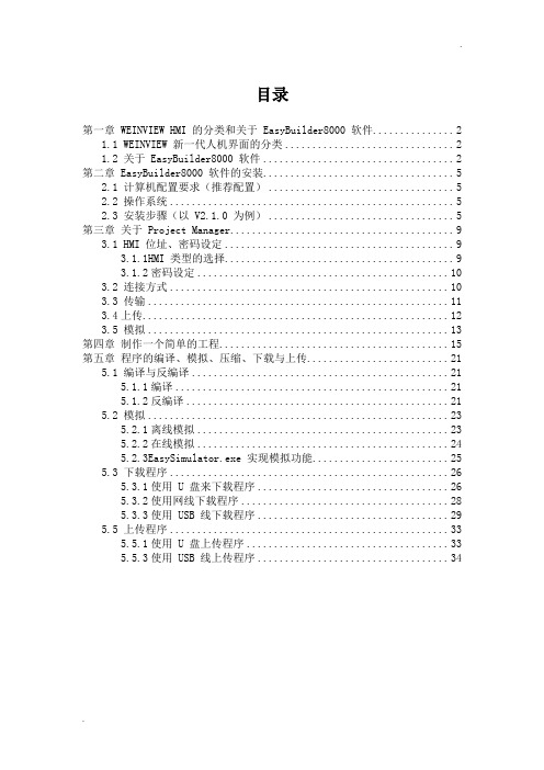
目录第一章 WEINVIEW HMI 的分类和关于 EasyBuilder8000 软件 (2)1.1 WEINVIEW 新一代人机界面的分类 (2)1.2 关于 EasyBuilder8000 软件 (2)第二章 EasyBuilder8000 软件的安装 (5)2.1 计算机配置要求(推荐配置) (5)2.2 操作系统 (5)2.3 安装步骤(以 V2.1.0 为例) (5)第三章关于 Project Manager (9)3.1 HMI 位址、密码设定 (9)3.1.1HMI 类型的选择 (9)3.1.2密码设定 (10)3.2 连接方式 (10)3.3 传输 (11)3.4上传 (12)3.5 模拟 (13)第四章制作一个简单的工程 (15)第五章程序的编译、模拟、压缩、下载与上传 (21)5.1 编译与反编译 (21)5.1.1编译 (21)5.1.2反编译 (21)5.2 模拟 (23)5.2.1离线模拟 (23)5.2.2在线模拟 (24)5.2.3EasySimulator.exe 实现模拟功能 (25)5.3 下载程序 (26)5.3.1使用 U 盘来下载程序 (26)5.3.2使用网线下载程序 (28)5.3.3使用 USB 线下载程序 (29)5.5 上传程序 (33)5.5.1使用 U 盘上传程序 (33)5.5.3使用 USB 线上传程序 (34)Easybuilder8000软件使用说明书第一章WEINVIEW HMI 的分类和关于 EasyBuilder8000 软件1.1 WEINVIEW 新一代人机界面的分类WEINVIEW 新一代嵌入式工业人机界面有 MT8000 和 MT6000 系列。
通过采用不同的 CPU,可分为 T 系列、i 系列和 X 系列。
他们的区别主要是:T 系列采用200MHz 32 bit RISC(精简指令集) CPU,32M 内存;i 系列采用 400MHz 32 bit Risc CPU,128M 内存;而 X 系列采用 500MHz, 32 bit CISC(复杂指令集)CPU,256M 内存。
繁易触摸屏资料
包装机械
• 电脑组合称专用触摸屏界面
技术特点: • 符合IP65 的手持式结构 设计 • 9.7英寸1024*768分辨 率高清高亮液晶显示屏 • 隔离电源模块设计,配 合客户提供DC12V和 24V供电的版本,更高 的抗干扰性能 • 铝合金前后壳机身
包装机械
• 卧式包装机专用控制系统
技术特点: • 控制器采用高性能AMR处理 器,通用的可编程软件平台 • 内置混合型输出,节省中间 继电器配置 • 集成4路高速脉冲功能和双编 码器计数功能,满足各种配 置的卧式包装机应用 • 集成多路温度PID控制功能, 温度探头采用热电偶 • 方便安装的导轨式板卡设计 ,可插拔端子方便接线 • 高性价比的专用方案
技术平台
行业定制
包装机械
特种车辆
医疗设备
制衣设备
机床设备
机器人
智能家居 电子设备
……
医疗设备
• X光机专用触摸界面
技术特点: • 多点式电容触摸屏 • 高速高效的ARM Cortex A8处理器 • 9.7英寸1024*768分辨 率高清高亮液晶显示屏 • 内置重力传感器,画面 可自动旋转 • 内置音频播放功能 • 简约外观设计,铝合金 机身
制衣设备
• 特种缝纫机手持操作界面
技术特点: • 专业工业设计的外观结构,符合特种缝纫 设计的操作和连接需求 • 7.0英寸800*480分辨率工规液晶屏,模拟 电阻触摸屏 • 定制化的软件解决方案,配合花样设计软 件提供文件管理和花样修改功能
电子设备
• BGA返修台一体化控制系统
技术特点: • 针对BGA返修台行业的集成化解决方案 • 7“触摸屏后背安装BGA专用控制板,降 低安装维护成本 • 集成4路热电偶温度检测,3路PID控制 • 集成功率输出模块,直接驱动加热组件, 节省固态继电器成本 • 专业的结构设计和工业防护设计,降低成 本的同时一样稳定可靠
Pro-face ST-6200WA基本HMI数据手册说明书
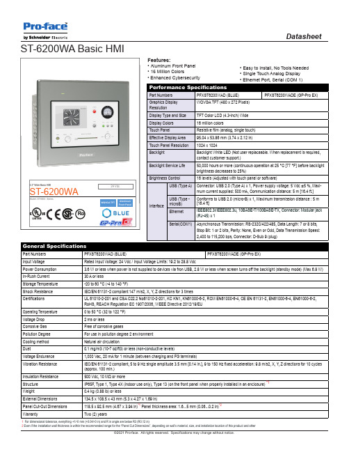
Operating Temperature
0 to 50 °C (32 to 122 °F)
Voltage Drop
2 ms or less
Corrosive Gas
Free of corrosive gases
Pollution Degree
For use in pollution degree 2 environment
16 million colors Resistive film (analog, single touch) 95.04 x 53.86 mm (3.74 x 2.12 in) 1024 x 1024
Backlight Backlight Service Life
Backlight White LED (Not user replaceable. When replacement is required, contact customer support.)
Serial(COM1) Asynchronous Transmission: RS-232C/422/485, Data Length: 7 or 8 bits, Stop Bit: 1 or 2 bits, Parity: None, Even or Odd, Data Transmission Speed: 2,400 to 115,200 bps, Connector: D-Sub 9 (plug)
Insulation Resistance Structure
500 Vdc, 10 MΩ or more IP65F, Type 1, Type 4X (indoor use only), Type 13 (on the front panel when properly installed in an enclosure) *1
- 1、下载文档前请自行甄别文档内容的完整性,平台不提供额外的编辑、内容补充、找答案等附加服务。
- 2、"仅部分预览"的文档,不可在线预览部分如存在完整性等问题,可反馈申请退款(可完整预览的文档不适用该条件!)。
- 3、如文档侵犯您的权益,请联系客服反馈,我们会尽快为您处理(人工客服工作时间:9:00-18:30)。
制衣设备
• 特种缝纫机手持操作界面
技术特点: • 专业工业设计的外观结构,符合特种缝纫 设计的操作和连接需求 • 7.0英寸800*480分辨率工规液晶屏,模拟 电阻触摸屏 • 定制化的软件解决方案,配合花样设计软 件提供文件管理和花样修改功能
电子设备
• BGA返修台一体化控制系统
技术特点: • 针对BGA返修台行业的集成化解决方案 • 7“触摸屏后背安装BGA专用控制板,降 低安装维护成本 • 集成4路热电偶温度检测,3路PID控制 • 集成功率输出模块,直接驱动加热组件, 节省固态继电器成本 • 专业的结构设计和工业防护设计,降低成 本的同时一样稳定可靠
贴近客户需求的定制化方案
繁易电子行业定制应用案例
繁易的由来
上海繁易电子科技有限公司总部和研发中心设在上海,生产工厂和物流中心设在深圳。繁易
为公司英文名称FLEXEM的音译,意为化繁为易;FLEXEM取Flexible与Embedded词首的组合, 意为灵活柔性的嵌入式系统开发设计。
产品和服务:
繁易依托自主的嵌入式软硬件平台技术,提供专业的软硬件产品和行业定制化解决方案。产品包
专注于您的核心能力,其它的交给繁易
繁易为您节省开发时间,提升开发效率,降低开发成本和产品成本,让您更加专注于自己的核心竞争力
注重设计,内外兼修
专业的工业设计团队,打造您完美的产品外观;经验丰富的研发团队,确保您产品稳定可靠的内在。
创新平台,化繁为易
繁易创新的软硬件开发平台,是快速高效行业定制的基础。设计专业,稳定可靠,界面友好,简单易用,充分释放 您的创造力。
智能家居
• 智能家居系统专用触摸屏
技术特点: • 简约工业设计外观,精巧的嵌墙安装结构 • ARM9内核高效处理器,WINCE操作系统 • 内置以太网,TF扩展功能 • 内置音频播放、温度探测功能 • DC12V的电源设计,符合家居安全规范
我们期待更多的案例来自 与您的合作! 谢谢!
• 自动模切专用磁粉离合器张力控制系统
技术特点: • 旧有的控制面板为单通道张力控制+LED显示模块的方式 • 存在显示不直观,布线困难,集成度低,故障率高等缺点 • 缓启动功能,短路保护和短路提醒功能方便故障诊断 • 铝合金外壳设计,可插拔端子方便接线 • 配合人机界面形成高性价比的一体化解决方案
特种车辆
• 特种车辆专用改装控制系统
技术特点: • 符合特种车辆车载设备规格的定制化系统 • 两台ARM Cortex A8处理器的7“触摸屏 以太网互联 • 集成双路视频监控功能,视频窗口可自动 切换 • 控制器采用金属结构定制,符合车载规范 ,集成4路电压检测功能 • 专业的结构设计和工业防护设计,保证车 载环境的稳定可靠
括工业电阻式 /多点电容式人机界面(HMI),可编程逻辑控制器(PLC),文本显示器和可编程协议 网关等产品。
繁易致力于帮助您降低产品的设计难度,缩短开发周期, 降低生产成本,以高可靠的设计提高您的产
品质量,节约您的开发时间,降低您的维护成本。
行业专家,量身定制
繁易为您提供量身定制的行业定制化产品解决方,充分尊重您的需求,打造最适合您的产品
包装机械
• 电脑组合称专用触摸屏界面
技术特点: • 符合IP65 的手持式结构 设计 • 9.7英寸1024*768分辨 率高清高亮液晶显示屏 • 隔离电源模块设计,配 合客户提供DC12V和 24V供电的版本,更高 的抗干扰性能 • 铝合金前后壳机身
包装机械
• 卧式包装机专用控制系统
技术特点: • 控制器采用高性能AMR处理 器,通用的可编程软件平台 • 内置混合型输出,节省中间 继电器配置 • 集成4路高速脉冲功能和双编 码器计数功能,满足各种配 置的卧式包装机应用 • 集成多路温度PID控制功能, 温度探头采用热电偶 • 方便安装的导轨式板卡设计 ,可插拔端子方便接线 • 高性价比的专用方案
医疗设备
• 电刀内嵌式触摸屏模块
技术特点: • 完全按客户产品结构的 定制化设计 • 5.0英寸800*480分辨率 液晶显示 • 高抗干扰等级设计 • 全金属内嵌式结构
医疗设备
• 灭菌柜专用控制系统
技术特点: • 完全按客户工艺要求定 制化设计 • 高性能ARM内核处理器 ,工艺程序客户可编辑 • 精密温度控制,温度探 头采用热电偶 • 气压传感器,探测压力 仓内气压 • 集成3路大功率输出模块 ,直接控制加热部件 • 高可靠性的工业设计
机床设备
• 锻压冲床专用控制面板
技术特点: • 完全客制化的面板结构设计,前壳 铝合金冲压成型,符合客户机箱尺 寸 • 内嵌4.3“触摸屏模块,标准编程 画面功能 • 集成4路指示灯,配合客户要求
机器人
• 多轴机器人手持教导界面
技术特点: • 专业工业设计的外观结构,符合机器人教 导设备的安全规范 • 8.0英寸1024*768分辨率高清高亮液晶屏 • 内置专业视频转换芯片,可以远程显示和 操控机器人控制计算机上的操作程序
技术平台
行业定制
包装机械
特种车辆
医疗设备
制衣设备
机床设备
机器人
智能家居 电子设备
……
医疗设备
• X光机专用触摸界面
技术特点: • 多点式电容触摸屏 • 高速高效的ARM Cortex A8处理器 • 9.7英寸1024*768分辨 率高清高亮液晶显示屏 • 内置重力传感器,画面 可自动旋转 • 内置音频播放功能 • 简约外观设计,铝合金 机身
繁易主要面向工业自动化,医疗,新能源及智能家居领域,提供高性价比,高可靠性,设计专业
,简单易用的定制化产品,并提供包括设计开发、贴牌生产和技术支持等服务。行业涵盖医疗, 包装,印刷,纺织,电子,工程,新能源,交通,建材,楼宇,智能家居等行业。多年 来,数十万计的繁易产品运行在各行各业的各种自动化设备上,在您看到和看不到的地方,都有 我们的产品在默默工作着。
医疗设备
• 手术室专用大尺寸控制面板
技术特点: • 32寸标清液晶显示 • 红外触摸屏 • 高速高效的ARM Cortex A8处理器 • 控制空调,灯光,器械参 数等,显示手术时间等信 息 • 内置电话对讲系统,支持 触摸屏拨号对讲 • 内置音频播放功能,可播 放背景音乐 • 简约外观设计,铝合金机 身
