HiPER 810 说明书
810脱毛说明书中文版
2.2.1 电路安全1,半自动化的电路闸位于操作仪表盘,保护系统因电负荷过重跳闸。
要想恢复正常操作举起电路闸手柄重启系统。
2,软件保护,有电子狗自动检测。
3,附属机头的自动检测。
4,电路回路的自动检测。
2.2.2. 激光安全1,封闭的几何光导装置用来发射激光到治疗区。
光仅通过光导装置的前面发出2,系统掺入了安全的遥控连接装置,连接入门的外部连接到治疗室,安装后,入门是开启的情况下系统不能正常操作。
3,必要时紧急关闭安全钮会加速关闭系统,停止操作。
5,激光发射只有在脚踏和机头手柄同时按下时起作用,手柄可防止无意识的激光散射。
6,一旦系统启动就有水循环给机器降温。
7,水的流动和温度会有调控,减少机头过热的风险。
如果水流停止或水温达到或超过40℃都将发射不出激光。
8,系统配备有气流控制的脚踏便于使用,以减少短路的风险2.3治疗室治疗时必须粘贴危险标志,室内不应有任何反射物,如镜子,必须做好防护,必要时戴眼罩。
2.4.1预防措施必须熟读本手册,要保持机头清洁,不可通过拉机头手柄拖动机器。
2.4.2注意事项1,不用的时候把系统关闭2.,没人看护的情况下,不要把系统设在待机模式3,没经过培训的人员不准开机4,不要拉动脚踏或机头手柄,除非安全的指向特定的目标5,系统做维护时,不要开动系统。
2.5.1烧伤风险该机器激光波长是810nm,人眼是不可视的,可能引起Ⅲ度烧伤2.5.2 直接和间接的激光暴露风险所有在治疗室内的人都应做好防护,操作者和客人尽可能都戴眼罩,即使客人带了眼罩也要嘱咐其闭眼,如果客人不能带眼罩必须戴一个不透明的东西做好防护,如果治疗区域非常靠近眼睛请戴上角膜保护板。
2.5.4激光吸收后会增加吸收体的温度,要预防烧伤风险,系统不适合在有氧气等可燃性气体存在的情况下使用,不要在有酒精、汽油、甚至溶剂的情况下使用。
皮肤消毒时不应使用可燃物质如酒精或丙酮,必要时可使用肥皂或水来清洁,如果使用酒精的话,必须完全干燥后再操作。
Shure SCM810八频道话筒混音器用户指南说明书
SCM810八頻道話筒混音器Shure SCM810 eight-channel microphone mixer user guide Version: 5.1 (2020-K)Table of ContentsSCM810 八頻道話筒混音器3重要安全事項! 3簡要說明3系統功能 4操作原則4前面板功能4後面板功能 5 DIP 開關 6在機架安裝混音器7 SCM810/E 連接 8輸出限制器設定 8等化器功能8透過自動混音器使用等化器/回饋控制器9基本混音器操作9連網多個混音器10全域/本機功能10連結纜線 11備件 11規格12服務聲明14認證14進階功能14 14邏輯連接規格 14建議的邏輯應用15內部修改20 201.2.3.4.5.6.7.8.9.10.11.12.13.14.15.16.17.18.19.20.21.SCM810八頻道話筒混音器重要安全事項!必須閱讀這些注意事項。
必須保留這些注意事項。
必須注意所有警告內容。
必須遵循所有注意事項。
不要在靠近水的地方使用本設備。
只能用幹布擦拭設備。
不要堵塞任何通風口。
留出足夠的距離,確保充分通風,並安裝在符合製造商要求的位置。
不要將本設備安裝在任何熱源(如明火、散熱器、調溫器、火爐或包括功率放大器在可的其它可能產生熱量的裝置附近。
不要將任何明火火源放置在產品上。
不要破壞帶極性或接地類型插頭的安全功能。
極性插頭帶有兩個插片,其中一個比另一個寬。
接地類型插頭帶有兩個插片和第三個接地插腳。
較寬的插片或第三個插腳是為安全目的設定的。
如果提供的插頭無法插入插座,請向電工諮詢如何更換合適的插座。
保護電源線防止被腳踩踏或被夾緊,尤其是在插頭、方便插座和機身電源線的引出處。
只能使用製造商指定的連接部件/附件。
只能使用製造商指定的或隨設備售出的手推車、支座、三角架、托架或支撐台。
如果使用手推車,在移動裝有設備的手推車時應注意安全,避免設備翻落。
在雷電天氣或長時間不使用時,應拔下設備的插頭。
Lorex NR810系列产品说明书

Router*HDMI OR* Not included / sold separately.** Cameras are included only with bundled systems. Stand-alone systems do not include cameras.For the best video output this NVR can provide, you must use it with a monitor that supports 4K resolution.!Quick Start GuidesUSB MouseEthernet CableFor PoE switch installations only.Ethernet Extension Cable*NOTE: It may take up to 1 minute for cameras to start up and transmit video to your NVR.Recommended: Connect cameras ORConnect cameras to a PoE switch*or router*your network. Visit Search for the model numberof your productwould like to playback. Click the display options( Using the Quick MenuRight-click to open the Quick Menu.Click and select SettingNR810_SERIES_QCG_EN_R1If the Status indicator is red, click Update the camera user name, password, 4. 5. Click Apply to save changes.Quick Access to System InformationTo quickly open a window that displays vital system information such as device ID, firmware version, and device IP address:1. During live view, right-click anywhere on the screen to open the Quick Menu.2. Click Info . If prompted, enter the system user name (default: admin ) and your new, secure password.321open the Navigation Bar. Move the mouse cursor away from the bottom of the。
OpenRun PRO S810 耳机说明书

OPEN RUN PROUser GuideContents HOW IT WORKS CARE AND MAINTENANCEEXTRA FEATURESCONTENTSCONTENTS TROUBLESHOOTINGWHAT’S IN THE BOX REGULATORY AND LEGAL INFORMATIONSHOKZ APPApple and the Apple logo are trademarks of Apple Inc., registered in the U.S. and other countries.Google Play is a trademark of Google LLC.ownload the Shokz App Manage multipoint pairing, upgrade firmware, change EQ modes, and more! Download the Shokz App to easily control headphone settings.*Only for limited regions.HEADPHONE CONTROLSON/OFFON/OFFflashes blue.*Audrey will say:“Press and hold the Power/Volume + Button until the LED Indicator flashes red.Pairing PAIRING2. Press and hold the Volume + Button until the LED Indicator flashes*Wearing your headphones the wrong way could causediscomfort. The transducers should rest in front of your ears.Pick up the headphones, bring them behind the back of the base of your neck,position the earhooks on your ears, then enjoy your music!HOW TO WEARVolume*Listening with headphones at high volume may affect your hearing and the audio will be distorted.*A “beep”Volume - ButtonVOLUMEMultifunction ButtonClick onceEnd callClick onceAnswer callClick oncePlay/pause musicDouble-click while music is playingNext songTriple-click while music is playingPrevious songMUL TIFUNCTION BUTTONMultifunction ButtonPress and hold for 2 seconds while a second incoming call is ringing.Click once while a second incoming call is ringing.Press and hold for 2 seconds while two calls are activeClick once while two calls are active.Click once Click oncePlay musicPause music Next song Previous songClick once Click onceDouble-click while music is playing Triple-click while music is playing Press and hold for 2 seconds Prompt device’s voice assistant Press and hold for 2 secondsAnswer call End call Reject a callAnswer a second call and decline th current callChange the languageAnswer a second incoming call and put the current call on hold Switch between two calls Hanging up on a multiparty call is the current callDouble click while in pairing status (red and blue lights flash alternately)MUL TIFUNCTION BUTTONCheck Battery StatusVolume - Button* "Battery high/Battery medium/Battery low/Charge me"CHECK BATTERY STATUSVocal Booster Mode:Enhanced intermediate frequencies for audiobooks, podcasts, etc.Standard Mode:Balanced frequency for listening to musicEQ MODESSWITCHING EQ MODES*Audrey will say:“Standard Mode/Vocal Booster Mode”*You can also use the shokz App to change the EQ modePair Two DevicesSwitch between two devices seamlessly with multipoint pairingOperate controls withLED indicator flashes red and blue alternately.*You can also use the Shokz App for easy switching between devices3.Press and hold the multifunction button and Volume + button until Audrey say "multipoint enabled."by Shokz."Audrey will say "connected".5.Turn your headphones off.6.Re-enter pairing mode by pressing and holding Volume + until Audrey says “pairing”and the LED indicator flashes red and blue alternately.7.Open second device's Bluetooth® menu and select "OpenRun Pro by Shokz."Audrey will say "connected."8.Turn your headphones off.9.Turn your headphones on. Your headphones are now connectedto both devices.Operate controls withand the LED indicator flashes red and blue alternately.*You can also use the Shokz App for easy switching between devices3. Press and hold the multifunction button and Volume - button until Audrey will say "multipoint disabled."2. Press and hold Volume + until Audrey will say “pairing”and the LED indicator flashes red and blue alternately.*You can also use the Shokz App to change the language.Your headphones have four built-in languages:Chinese, English, Japanese and Korean.CHANGING LANGUAGES3. Double-press the multifunction button. Languages have beenswitched when you hear the corresponding language.CHANGE THE LANGUAGECharging Tips CHARGING TIPSheadphones will automatically turn off. The LED indicator will turnMoisture Detection Alert How it Works:beep. If this happens, remove the charging cable, dry them completely, then proceed with charging.MOISTURE DETECTION ALERTSTORAGE AND MAINTENANCE· Store the headphones in a cool, dry place. The working temperature should be 0~45°C(32~113°F).Working in a cold/hot temperature, highly humid area, or low air pressure environment may reduce the battery life.· Keep the product away from heat sources, direct sunlight, combustible gas or other liquids.· Keeping the charging port dry before connecting to the charger will reduce the risk of damage.· These headphones are water-resistant, but are not waterproof. Please do not submerse the headphones in water.· Clean the headphones with a soft dry cloth.· Do not charge right after exercising, in case there's sweat inside the charging port, which could lead to circuit burning while charging.· After storage for a long period, please charge the headphones before using again.NoteDesign and specification are subject to change without notice. For the most up-to-date product information, please visit https:// WarningTo avoid the risk of explosion, fire, or leakage from toxic chemicals, please do not disassemble the product or replace, deform, or mutilate the battery.WARRANTYYour headphones are covered by a warranty.Visit our website at https:///pages/warranty-landing for details of the limited warranty.To register your product, download the Shokz App.*Failure to register will not affect your limited warranty rights.TROUBLESHOOTINGIf you have any trouble or problems,please visit https:///pages/faqfor more support!If any part of your product is damaged or missing, do not use it.Contact authorized Shokz dealer or Shokz customer service.*Please note that the packaging envelope may vary depending onthe sales region.WHAT’S IN THE BOXOpenRun Pro headphones OpenRun Pro PackageOpenRun ProBoxOpenRun Pro App Card OpenRun Pro User Guide User Guide OpenRun Pro Legal Statement Legal Shokz AppFCC CautionAny changes or modifications not expressly approved by the party responsible for compliance could void the user's authority to operate the equipment. This device complies with Part 15 of the FCC Rules. Operation is subject to the following two conditions:(1) this device may not cause harmful interference, and(2) this device must accept any interference received, including interference that may cause undesired operation.FCC StatementThis equipment has been tested and found to comply with the limits for a Class B digital device, pursuant to part 15 of the FCC Rules. These limits are designed to provide reasonable protection against harmful interference in a residential installation. This equipment generates, uses and can radiate radio frequency energy and, if not installed and used in accordance with the instructions, may cause harmful interference to radio communications. However, there is no guarantee that interference will not occur in a particular installation. If this equipment does cause harmful interference to radio or television reception, which can be determined by turning the equipment off and on, the user is encouraged to try to correct the interference by one or more of the following measures:-Reorient or relocate the receiving antenna.-Increase the separation between the equipment and receiver.-Connect the equipment into an outlet on a circuit different from that to which the receiver is connected.-Consult the dealer or an experienced radio/TV technician for help. This equipment complies with FCC/IC radiation exposure limits set forth for an uncontrolled environment and meets the FCC radio frequency (RF) Exposure Guidelines and RSS-102 of the IC radio frequency (RF) Exposure rules. This equipment has very low levels of RF energy that is deemed to comply without testing of specific absorption rate (SAR).Frequency Range Max. Transmit Power 2400-2483.5MHz 10dBm(EIRP)Resposible party (contact for FCC matters only):AfterShokz LLC.3200 Gracie Kiltz Lane, Suite 400 Austin, TX 78758 USA https:// Industry Canada This device complies with Industry Canada licence-exempt RSS standard(s): Operation is subject to the following Two conditions: (1) this device may not cause interference, and (2) this device must accept any interference, including interference that may cause undesired operation of the device.CE Declaration of Conformity Shokz Holding Limited hereby declares that this product is in compliance with the essential requirements and other relevant provisions of Directive 2014/53/EU and all other applicable EU Directive requirements. The complete declaration of conformity can be found at: https:///pages/policies. Shokz’s EU representative is AfterShokz Euro B.V., Schipholweg 103, 2316XC Leiden, Declaration of Conformity Shokz Holding Limited hereby declares that this product is in compliance with the essential requirements and all other applicable United Kingdom’s regulations. The complete declaration of conformity can be found at: https:///pages/policies. Shokz’s authorised representative in the UK is Pinpoint Consumer Electronics Ltd., Unit 35, Meridian House, Road One, Winsford Industrial Estate, Winsford, Cheshire CW7 3QG.WEEE Declaration of ConformityThis WEEE logo means that this product must not be discardedas household waste, and should be delivered to an appropriate collection facility for recycling. Proper disposal and recycling helps protect natural resources, human health and the environment. For more information on disposal and recycling of this product, contact your local municipality, disposal service, or the shop where you bought this product. Manufacturer Declarations Warranty: Shokz Holding Limited gives a warranty of 24 months on this product. For the current warranty conditions, please visit our website at https:// or contact your Shokz partner. Before putting the product into operation, please observe the respective country specific regulations.Australia/New Zealand SingaporeDA107248。
JBL QUANTUM810 WIRELESS游戏耳机说明书

810WIRELESSO W N E R’S M A N U A LINTRODUCTION (1)WHAT’S IN THE BOX (2)PRODUCT OVERVIEW (3)Controls on headset (3)Controls on 2.4G USB wireless dongle (5)Controls on 3.5mm audio cable (5)GETTING STARTED (6)Charging your headset (6)Wearing your headset (7)Power on (8)First-time setup (for PC only) (8)USING YOUR HEADSET (10)With 3.5mm audio connection (10)With 2.4G wireless connection (11)With Bluetooth (secondary connection) (13)PRODUCT SPECIFICATIONS (15)TROUBLESHOOTING (16)LICENSE (18)Congratulations on your purchase! This manual includes information on the J BL QUANTUM810 WIRELESS gaming headset. We encourage you to take a few minutes to read this manual, which describes the product and includes step-by-step instructions to help you to set up and get started. Read and understand all the safety instructions before using your product.If you have any questions about this product or its operation, please contact your retailer or customer service, or visit us at 010*******0601 JBL QUANTUM810 WIRELESS headset02 USB charging cable (USB-A to USB-C)03 3.5mm audio cable04 2.4G USB wireless dongle05 QSG, warranty card and safety sheet06 Windshield foam for boom microphoneControls on headset01 ANC* / TalkThru** LED• Lights up when the ANC feature is enabled.• Flashes quickly when the TalkThru feature is enabled.02 button• Press briefly to turn ANC on or off.• Hold for more than 2 seconds to turn TalkThru on or off.03 / dial• Balances the chat volume in relation to the game audio volume.04 Volume +/- dial• Adjusts headset volume.05 Detachable windshield foam06 Mic mute / unmute LED• Lights up when the microphone is muted.07 button• Press to mute or unmute the microphone.• Hold for more than 5 seconds to turn the RGB light on or off.08 Charging LED• Indicates the charging and battery status.09 3.5mm audio jack10 USB-C port11 Voice focus boom microphone• Flip up to mute, or flip down to unmute the microphone.12 button• Hold for more than 2 seconds to enter Bluetooth pairing mode.13 slider• Slide upwards / downwards to power on / off the headset.• Slide upwards and hold for more than 5 seconds to enter 2.4G pairing mode.14 Status LED (Power / 2.4G / Bluetooth)15 RGB Lighting Zones16 Flat-fold ear cup* ANC (Active Noise Cancelling): Experience total immersion while gaming by suppressing the outside noise.** TalkThru: In TalkThru mode, you can hold natural conversations without removing your headset.020101 CONNECT button• Hold for more than 5 seconds to enter 2.4G wireless pairing mode.02 LED• Indicates the status of 2.4G wireless connection. Controls on 3.5mm audio cable01 slider•02 Volume dial•Charging your headsetBefore use, fully charge your headset through the supplied USB-A to USB-C charging cable.TIPS:• It takes approximately 3.5 hours to fully charge the headset.• You can also charge your headset through a USB-C to USB-C charging cable (not supplied).Wearing your headset1. Put the side marked L onto your left ear and the side marked R onto your right ear.2. Adjust the earpads and headband for a comfortable fit.3. Adjust the microphone as necessary.Power on• Slide the power switch upwards to power on the headset.• Slide downwards to power off.The status LED glows solid white upon powering on.First-time setup (for PC only)Download from /engine to gain full access to features on your J BL Quantum headset - from headset calibration to adjusting 3D audio to suit your hearing, from creating customized RGB lighting effects to determining how the boom microphone side-tone works.Software requirementsPlatform: Windows 10 (64 bit only) / Windows 11500MB of free hard drive space for installationTIP:• QuantumSURROUND and DTS Headphone:X V2.0 available on Windows only.Software installation required.1. Connect the headset to your PC via2.4G USB wireless connection (See “With 2.4Gwireless connection”).2. Go to “Sound Settings” -> “Sound Control Panel”.3. Under “Playback” highlight “JBL QUANTUM810 WIRELESS GAME” and select“Set Default” -> “Default Device”.4. Highlight “JBL QUANTUM810 WIRELESS CHAT“ and select “Set Default” ->“Default Communication Device”.5. Under “Recording” highlight “JBL QUANTUM810 WIRELESS CHAT” and select“Set Default” -> “Default Device”.6. In your chat application select “JBL Q UANTUM810 WIRELESS CHAT” as thedefault audio device.7. Follow the onscreen instructions to personalize your sound settings.With 3.5mm audio connection1. Connect the black connector to your headset.2. Connect the orange connector to the3.5mm headphone jack on your PC, Mac,mobile or gaming console device.Basic operationNOTE:• The mic mute / unmute LED, button, / dial and RGB Lighting Zones on the headset do not work in 3.5mm audio connection.With 2.4G wireless connection1. Plug the2.4G USB wireless dongle into a USB-A port on your PC, Mac, PS4/PS5 orNintendo Switch™.2. Power on the headset. It will pair and connect with the dongle automatically. Basic operationTo pair manually1. On the headset, slide the power switch upwards and hold for more than 5 secondsuntil the status LED flashes white.2. On the 2.4G USB wireless dongle, hold CONNECT for more than 5 seconds untilthe LED flashes white quickly.Both LEDs on the headset and dongle turn solid white after successful connection.TIPS:• The headset turns off automatically after 10 minutes of inactivity.• The LED enters connecting mode (flashing slowly) after disconnection from the headset.• Compatibility with all USB-A ports is not guaranteed.With Bluetooth (secondary connection)With this function, you can connect your mobile phone to the headset while playing games, without worrying about missing important calls.1. Hold on the headset for more than 2 seconds.The status LED flashes quickly (pairing).2. Enable Bluetooth on your mobile phone and choose “JBL Q UANTUM810WIRELESS” from “Devices”.The status LED flashes slowly (connecting), and then turns solid blue (connected).Control calls×1×2When there is an incoming call:• Press once to answer.• Press twice to reject.During a call:• Press once to hang up.TIP:• Use volume controls on your Bluetooth connected device to adjust volume.• Driver size: 50 mm Dynamic drivers• Frequency response (Passive): 20 Hz - 40 kHz• Frequency response (Active): 20 Hz - 20 kHz• Microphone frequency response: 100 Hz -10 kHz• Max input power: 30 mW• Sensitivity: 95 dB SPL @1 kHz / 1 mW• Maximum SPL: 93 dB• Microphone sensitivity: -38 dBV / Pa@1 kHz• Impedance: 32 ohm• 2.4G Wireless transmitter power: <13 dBm• 2.4G Wireless modulation: GFSK, π/4 DQPSK• 2.4G Wireless carrier frequency: 2400 MHz - 2483.5 MHz• Bluetooth transmitted power: <12 dBm• Bluetooth transmitted modulation: GFSK, π/4 DQPSK• Bluetooth frequency: 2400 MHz - 2483.5 MHz• Bluetooth profile version: A2DP 1.3, HFP 1.8• Bluetooth version: V5.2• Battery type: Li-ion battery (3.7 V / 1300 mAh)• Power supply: 5 V 2 A• Charging time: 3.5 hrs• Music play time with RGB lighting off: 43 hrs• Microphone pickup pattern: Unidirectional• Weight: 418 gNOTE:• Technical specifications are subject to change without prior notice.If you have problems using this product, check the following points before you request service.No power• The headset turns off automatically after 10 minutes of inactivity. Power on the headset again.• Recharge the headset (see “Charging your headset”).2.4G pairing failed between headset and 2.4G USB wireless dongle • Move the headset closer to the dongle. If the issue remains, pair the headset with the dongle again manually (see “To pair manually”).Bluetooth pairing failed• Make sure you have enabled Bluetooth feature on the device to be connected with the headset.• Move the device closer to the headset.• The headset is connected to another device through Bluetooth. Disconnect the other device, then repeat the pairing procedures. (see “With Bluetooth (secondary connection)”).No sound or poor sound• Make sure you have chosen JBL QUANTUM810 WIRELESS GAME as the default device in the game sound settings of your PC, Mac or gaming console device.• Adjust volume on your PC, Mac or gaming console device.• Check game chat balance on PC if you are only playing game or chat audio.• Check that ANC is enabled while TalkThru is disabled.• You may experience obvious sound quality degradation when using the headset near a USB 3.0 enabled device. This is not a malfunction. Use an extension USB dock instead to keep the dongle as far from the USB 3.0 port as possible.In 2.4G wireless connection:• Make sure the headset and 2.4G wireless dongle are paired and connected successfully.• The USB-A ports on some gaming console devices may be incompatible with JBL QUANTUM810 WIRELESS. This is not a malfunction.In 3.5mm audio connection:• Make sure the 3.5mm audio cable is connected securely.In Bluetooth connection:• The volume control on the headset does not work for the Bluetooth connected device. This is not a malfunction.• Keep away from sources of radio interference such as microwaves or wireless routers.My voice cannot be heard by my teammates• Make sure you have chosen JBL QUANTUM810 WIRELESS CHAT as the default device in the chat sound settings of your PC, Mac or gaming console device.• Make sure the microphone is not muted.I can’t hear myself when I’m talking• Enable sidetone via to hear yourself clearly over game audio. ANC/TalkThru will be disabled when sidetone is enabled.The Bluetooth® word mark and logos are registered trademarks owned by Bluetooth SIG, Inc. and any use of such marks by HARMAN International Industries, Incorporated is under license. Other trademarks and trade names are those of their respective owners.HP_JBL_Q810_OM_V2_EN。
拓普康GPSHiper说明书
3. 注 册 商 标 : HiPerTM , LegacyTM , LegAntTM , Topcon
Positioning SystemTM,Topcon®是拓普康定位系统公司(TPS)
Hiper 用户手册.doc
3
的注册商标。Windows®是微软公司的注册商标。手册中提 到的其它公司及其的产品都有自己的注册商标。
块是 GPS+接收机板,另一块是通讯板(Modem、数传
电台、蜂窝电话或 DGPS)。
Euro80 板(HiPer 内置主板)有两种不同的 GPS+类型:
·GD—20 个通用通道,接收机能够接收和处理最多
20 个 GPS L1/L2 和 WAAS 信号。
·GG—20 个通用通道,接收机能够接收和处理最多
实时差分定位的接收机,可选择下列 5 种不同类型的通 讯板:
• PCC 的 PDL 接收电台(450-470MHz) • PCC 的 PDL 接收电台(430-450MHz) • 扩频电台 - 915MHz • 扩频电台 - 2.4GHz • 双频带双用户 GSM(蜂窝电话)
- 欧洲和日本:900/1800MHz - 美国和加拿大:900/1900MHz • TPS-BDR(广播数据接收机):接收从DGPS无线电信 标台发射的差分改正数据和L波段地球同步卫星广播 的OmniStar○R数据。 本手册中,一般描述的是最为通用的配置:GD 型主板加 PDL 接收电台(450-470MHz)。在附录 C 中的技术指标中包括 HiPer GD 和 HiPer GG 两种类型。
1.2 HiPer 接收机外观
HiPer 标准配置包括两个串口和一个外接电源口。串口为 A 口和 D 口。串口 A 通常被用于 HiPer 与计算机或手簿间进行通 讯,图 3a 和图 3b 分别为 HiPer 接收机的前面板和后面板图。
海本平板电脑中文P810中文说明书

平板手写笔记本电脑产品说明书敬告尊敬的用户:感谢您购买和使用我公司的产品。
为了您的安全和利益,在使用产品前请您仔细阅读本产品说明书及随机附带的全部资料。
如果您未按照产品说明书操作和使用产品,而导致任何的人身伤害、财产或其他损失,本公司将不承担责任。
关于本产品说明书(以下简称“说明书”)♦说明书版权属于我公司所有;♦说明书提及的商标、字号属于它们各自的权利拥有者;♦说明书内容如有同实际产品不一致,以实际产品为准。
如果您对说明书中的内容或条款存在不明或异议,请在购机七日内向我司提出书面异议,否则视为您已经同意、理解并接受说明书全部内容。
平板手写笔记本电脑产品说明书目录1 注意事项 (3)1.1特别提示 (3)1.2笔记本使用重要提示—请务必阅读 (3)1.3注意事项 (4)1.4笔记本电脑电池使用须知—请务必阅读 (5)1.5安全须知 (7)2 产品概述 (9)2.1简介 (9)2.2部件介绍 (9)2.3开箱和检查 (12)3 基本使用常识 (13)3.1系统状态指示灯 (13)3.2显示屏 (14)3.3网卡 (14)4 BIOS(基本输入输出系统)设定 (16)4.1使用BIOS S ETUP 的方法 (16)4.2M AIN(主要设定) (17)4.3BOOT(开机画面及开机设备次序设定) (18)4.4S ECURITY S ETTINGS (密码保护设定) (19)4.5[E XIT]菜单 (20)5 驱动程序安装与使用说明 .................................................................... 错误!未定义书签。
5.1安装驱动程序,请您按以下步骤 .................................................. 错误!未定义书签。
6 故障分析与处理 (22)6.1声音的问题 (22)6.2硬盘的问题 (22)6.3显示器的问题 (23)6.4内存的问题 (23)特别声明 (24)附录A 产品规格 (25)平板手写笔记本电脑产品说明书平板手写笔记本电脑产品说明书1 注意事项1.1 特别提示为了便于理解和引起您的注意,当涉及产品安全或需关注的信息时我们将在本章节或在后面的章节中按下列等级和特别的警示用语向您提示,这些特别的警示用语表示方法如下:♦【危险】--表示对高度危险要警惕♦【警告】--表示对中度危险要警惕♦【注意】--表示对轻度危险要关注♦【禁止】--表示危险的操作需禁止♦【提醒】--表示安全或其他内容需关注本章节中为您提供的安全信息并不是全部的,为了您的安全和利益,我们会根据需要将部分产品安全信息编排到说明书的后面章节中,不论这些安全信息置于何处,您均应仔细阅读。
艾泰路由器的上网限制和功能管理的设置操作

艾泰路由器的上网限制和功能管理的设置操作标准化管理处编码[BBX968T-XBB8968-NNJ668-MM9N]艾泰路由器型号:型号:HiPER 810版本:一、上网设置---基本配置1、上网方式接入那里,如果你是ADSL拨号上网就选PPPOE拨号上网选项------下一步----将电信运营商提供给你的上网账号和密码分别填写在用户名和密码处,然后点下面的完成就可以了。
就进入不可不防处,按默认点完即可。
2、如果你是光纤方式专线上网,就点第二项固定IP接入,然后点下一步,将电信运营商提供给你的网关填入静态网关处,将IP地址填入广域网IP地址处,将子网掩码填入广域网子网掩码处,将DNS填入下面的主DNS处和备用DNS处,最后点成。
就进入不可不防处,按默认点完即可。
二、限速功能的设置。
首页点击智能带宽管理,在启用限速功能前的方框内打钩。
点击限速规则点地址组,在地质组名称那里自己随意取一个名字,如:限速,在起始地址处填写你要限速的IP地址,如:,在结束地址处填写。
即在这个IP地址范围内的计算机上网将被限速。
填写完后点添加,然后点完成。
在最大上行带宽处填写512,最大下行带宽处填写1536。
服务组那里点击右侧的箭头,即所有服务。
最后点击保存。
提示操作成功,确定。
如果想限制某一台电脑,则输入某一台电脑的IP地址。
如果限制迅雷等下载工具占用带宽,则启用P2P限速,上行限制512kb、下行1024kb。
二、限制玩QQ聊天等功能。
首页------安全配置选项----上网行为管理。
在地址组那里选你要限制的对象,这里按以上限制的地址组192……2-----192……100为例,在下面QQ前的方框内打钩,然后点下面的保存。
提示操作成功,点确定。
以上就完成了指定电脑的限速和限制某些电脑上网行为的设置管理。
其他的上网行为限制可以以此类推。
艾泰产品线介绍

–
– – –
上网行为管理、行为审计、日志管理
智能弹性流控 PPPoE Server认证/计费/通告 多协议VPN:IPSec、PPTP
商睿系列产品简介
商睿 4330G 产品定位
商睿 4240G: 19英寸、4个百兆WAN、5个千 兆LAN,带机量200-700,PPPoE Server (200)、30条VPN
电气特性 指示灯 工作温/湿度
POE供电交换机产品简介
S1088GP/S11624P-POE交换机
S1088GP
S1624P
产品概述 – – 8个1000M自适应电口,1~8口支持POE供电,内置150W工业电源 24个100M自适应电口,1~16口支持POE供电,内置250W工业电源
卖点总结
宽带网关详细规格参数
型号 尺寸 WAN LAN 主频 进取 521G 11英寸 2千兆WAN 3千兆LAN Ralink 500MHz 进取 1220G 19英寸 2千兆WAN 3千兆LAN Ralink 500MHz
内存/Flash
带机量 电源/功耗
64M/8M
80-100 AC 100-240V 10W
80
80 120
1
1-4 千兆 4
4
1-4 千兆 4
√
√ √
√
√ √
√
√ √
—
— √
商睿系列机架型产品简介
型号 2610 2620 3320G 3520G 4220G 尺寸 19 19 19 19 19 带机量 150 150 150 120 300 LAN口 WAN口 数量 数量 4 4 4-1千 兆 24 千兆 5 千兆 5 千兆 4千兆 4 千兆 1 2 1-4千兆 2 2 上网行 为管理 √ √ √ √ √ 带宽 管理 √ √ √ √ √ PPPoE 服务器 — — √ √ √ VPN — √ √ √ √
韶音OPENRUN PRO S810使用手册说明书

OPEN RUN PRO使用指南目錄如何使用維護保養擴充功能監管與法律資訊盒內物品目錄下載Shokz App Shokz App支援雙設備連接、韌體升級、調整音效模式等多種功能。
即刻下載,您可輕鬆享受更便捷的使用體驗。
**部分地區暫未上架Shokz App ,請訪問/openrunpro瞭解更多資訊。
下載SHOKZ APP耳機圖示耳機圖示開關機電源/音量+鍵開機:關機:按住電源/音量+鍵直至紅燈閃爍,*這時將聽到語音提示:“ Power off ”開關機“電源/音量+鍵”。
,配對配對*使用耳機時需要注意正確佩戴,錯誤的佩戴方式將引起您的不適,耳機發聲部位應該在您雙耳的前方,無需塞入耳內。
雙手分開耳機,佩戴至適合的位置,享受音樂的陪伴佩戴佩戴操作方法:,滿足您的使用需求。
音量(ー)鍵音量調整聲進行提示。
音量調整通話時按一次掛斷電話 來電時按一次接聽電話按一次播放/暫停音樂歌曲播放時連按兩次下一首歌曲歌曲播放時連按三次上一首歌曲多功能鍵多功能鍵更多功能第二個電話打入時,長按多功能按鍵�秒第二個電話打入時,按一次多功能按鍵多方通話狀態下,長按多功能按鍵�秒多方通話狀態下,按一次多功能按鍵非電話播放狀態下,按一次多功能鍵接第二個電話,同時掛第一個電話切換提示音的語言接第二個電話,同時保持第一個電話迴圈接聽(切換到保持的電話)掛斷多方通話是當前通話的電話配對狀態(紅藍燈交替閃爍)下,連按兩次多功能鍵多功能鍵*以上功能涉及通話的部分,僅適用於電話通話,不適用於協力廠商軟體或第三方軟體進行的語音通話或視頻通話等。
適用功能及範圍,以官方公布為準。
播放暫停下一首上一首語言助手接電話掛電話拒接電話播放狀態下,按一次多功能鍵播放狀態下,連按兩次多功能鍵播放狀態下,連按三次多功能鍵長按多功能按鍵�秒按一次多功能鍵按一次多功能鍵長按多功能鍵需在耳機待機檢查電量操作方法:在耳機待機狀態下,(-)鍵,*語音提示內容:Charge me音量(ー)鍵檢查電量人聲模式:強化中頻,適用於聽廣播、電子書等音訊標準模式:頻段均衡,適用於聽音樂EQ模式說明EQ模式說明EQ模式切換操作方法:,保持�秒,鬆開按鈕切換到播報的模式。
中泰克810T1A5说明书V3.1.

810T1门禁控制器用户手册810T1系列智能门禁控制器使用说明书- -1 目 录 第一章 产品简介21.1结构示意...............................................................2 1.2.1 用户管理.........................................................2 1.2.2 支持多种方式开门.............................................2 1.2.3支持 RS485 或TCP/IP 联网.................................3 1.2.4 用户准进时段的控制..........................................3 1.2.5 增加/删除用户开门卡操作.................................3 1.2.6 通信地址码的设定.............................................4 1.2.7 环境监控、事件管理..........................................5 1.2.8 支持多种电控锁................................................5 1.2.9 详细的历史记录................................................5 1.2.10 重置控制器设置密码.......................................6 1.3系统设定...............................................................6 1.3.1感应卡号码的获取控制.......................................6 1.3.2联网通信.........................................................8 1.3.3门控参数.........................................................8 1.4 技术指标...............................................................9 2.1安装前准备............................................................11 2.1.1 了解安装环境................................................11 2.1.2 了解控制器的部件组成....................................11 2.1.3 仔细检查控制器内的跳线设置...........................12 2.1.4 熟悉控制器接线端子.......................................12 2.2 控制器的安装及系统接线.......................................14 2.2.1 安装............................................................14 2.2.2 系统接线......................................................14 2.2.3 第二继电器报警输出接线 (16)附录1:上位机读取810T1系列记录注意事项17 附录2:卡号获取方法说明.................................18 附录3:疑难问题解答 (20)问题1:刷卡没反应......................................................20 问题2:刷卡有反应但刷卡不开门....................................20 问题3:联网不通.........................................................20 问题4:怎样增加RS485的通信距离.................................21 问题5:关门后报警......................................................21 问题6:怎样关闭 “门状态”报警?.................................21 问题7:不能正常开门...................................................21 问题8:为什么手动开门按键没有反应?..............................21 问题9:为什么会误开门?................................................21 问题10:为什么控制器频繁“滴”声? (21)810T1系列智能门禁控制器使用说明书- -2第一章 产品简介1.1结构示意810T1系列出入口管理控制器由控制主板、显示灯、金属盒、开关电源、外接RF 感应头、红外、门磁、联动输入等功能模块组成。
BackBeat GO 810 耳机用户指南说明书
BackBeat GO serie 810 Guida dell'utenteSommarioAssociazione3Procedura di associazione3Associazione di un secondo dispositivo3Associazione a Mac3Ricarica4Ricarica4Operazioni preliminari5Panoramica dell'auricolare5Accensione/spegnimento5Riproduzione/Pausa di un brano musicale5Selezione delle tracce5Attivazione della funzione vocale6Esecuzione/ricezione/termine di chiamate6Esclusione microfono6Cancellazione del rumore attiva6Impostazione dell'EQ6Trovate il vostro prodotto ideale6Supporto712••312Selezionare "PLT serie BBGO800" nelle impostazioni Bluetooth del dispositivo.Se il dispositivo Mac dispone della funzione Bluetooth, è possibile associarvi le cuffie.1Impostare le cuffie in modalità di associazione (far scorrere e tenere il pulsante di accensione versol'icona Bluetooth). Si sentirà "pairing" (associazione) e i LED lampeggeranno in rosso e blu.2Sul dispositivo Mac, selezionare menu Apple > Preferenze di Sistema > Bluetooth .3Fare clic su Imposta nuovo dispositivo o su "+", selezionare "PLT serie BBGO800 stereo" e seguirele istruzioni visualizzate.AssociazioneProcedura di associazioneAssociazione di un secondo dispositivoAssociazione a MacLa ricarica completa dell'auricolare richiede fino a 120 minuti. I LED si spengono una volta che laricarica è completa.accensione/Bluetooth mentre si indossa l'auricolare. L'auricolare deve trovarsi in stato inattivo.L'auricolare garantisce fino a 22 ore di ascolto con cancellazione del rumore attiva (ANC) attivata e 28 ore di ascolto con cancellazione del rumore attiva (ANC) disattivata.RicaricaRicaricaCancellazion e del rumore attiva Cancellazione del rumore attiva Comandi di aumento del volume Comandi di diminuzione del volume Ricerca traccia in avanti Riproduzione/Pausa di un brano musicale Ricerca traccia indietro Pulsante di chiamata Siri, Google Now Funzione vocale Pulsante di associazione Bluetooth Accensione/spegnimento LED sulle cuffie Esclusione/riattivazione microfono Impostazioni EQ Far scorrere l'interruttore per accendere o spegnere.Toccare il pulsante di riproduzione/pausa .Toccare il pulsante avanti o indietro per controllare la selezione dei brani.Operazioni preliminariPanoramica dell'auricolareAccensione/spegnimentoRiproduzione/Pausa di un brano musicaleSelezione delle tracceSe lo smartphone dispone di una funzione vocale, tenere premuto il pulsante di riproduzione/pausa per 2 secondi e attendere la richiesta di comando vocale.Risposta e termine di una chiamata Toccare il pulsante di riproduzione/pausa .Rifiuto di una chiamata Tenere premuto il pulsante di riproduzione/pausa per 2 secondi.Richiamare l'ultimo numero (smartphone)Per chiamare l'ultimo numero che è stato composto, toccare due volte il pulsante di riproduzione/pausa .Durante una chiamata attiva, toccare il pulsante EQ/esclusione cancellazione del rumore attiva (ANC) riduce i rumori esterni e migliora la qualità della musica e dell'audio.1Tenere premuti i pulsanti di aumento e riduzione del volume per due secondi per attivare o disattivare la cancellazione del rumore attiva (ANC).2È possibile personalizzare ulteriormente la cancellazione del rumore attiva (ANC) con l'app BackBeat scegliendo:•Basso: opzione consigliata per l'ufficio •Elevato: opzione consigliata per l'aereo È possibile personalizzare l'audio e scorrere le modalità EQ toccando il pulsante EQ. È possibile anche cambiare modalità EQ attraverso l'app BackBeat.•Bilanciato (impostazione predefinita): ottimizza le frequenze per ottenere un suono migliore adatto a diversi generi di musica con bilanciamento dei bassi, medi e alti.•Alti : potenzia le frequenze degli alti per aumentare il livello di dettaglio e di nitidezza della musica e rendere il parlato più intelligibile.Nella maggior parte dei casi, l'auricolare si trova sotto i sedili dell'auto, in tasca o in un cassetto disordinato. Per le posizioni meno ovvie, potete trovare l'auricolare inviando un segnale acustico.1Scaricate l'app BackBeat visitando l'Apple App Store, Google Play o /software .2Trovate il vostro dispositivo smarrito usando la funzione Find MyHeadset all'interno dell'app.Attivazione della funzione vocaleEsecuzione/ricezione/termine di chiamateEsclusione microfonoCancellazione del rumore attivaImpostazione dell'EQTrovate il vostro prodotto idealeSupportoULTERIORI INFORMAZIONI/supportPlantronics, Inc.Plantronics B.V.345 Encinal Street Santa Cruz, CA 95060 United States Scorpius 171 2132 LR Hoofddorp Netherlands© 2018Plantronics, Inc. BackBeat e Plantronics sono marchi di Plantronics, Inc. registrati negli Stati Uniti e in altri paesi e Plantronics Hub è un marchio registrato di Plantronics, Inc. Bluetooth è un marchio registrato di Bluetooth SIG, Inc. e il suo uso da parte di Plantronics è concesso su licenza. Tutti gli altri marchi sono di proprietà dei rispettivi proprietari.Brevetti in attesa di approvazione.212987-16 (08.18)。
爱丽丝810说明书

爱丽丝810说明书810半导体冰点激光脱毛仪的工作原理:利用仪器特有的长脉宽808纳米的激光,穿透至毛囊部位,依据选择性光热作用原理,毛发固有的色素超出正常组织,激光的能量被毛法中的黑色素优先吸收,继而使毛干和毛囊被迅速加热,从而摧毁毛囊以及毛囊周围的供氧组织;在激光输出的同时,系统独有的超强冷却技术,在短时间内对表皮造成一定的麻醉作用,有效的确保了表皮不受激光能量的灼烧。
从而实现了安全有效的治疗!二、808半导体冰点激光脱毛仪的治疗范围:超级脱毛:适用各种皮肤的腋毛、唇毛、四肢毛、发髻线等身体各部位多余黑色毛发;也适合安全快速地去除各种颜色毛发。
三、808半导体冰点激光脱毛仪的治疗优势:1.安全性好:低能量高频率压迫式快速滑动技术,真正安全。
2.舒适性高:-1℃-5℃蓝宝石冷却无痛,10x16mm光斑面积,10Hz高频率治疗真正快速。
3.有效性强:核心808半导体技术,高能量密度输出,能量能达到深度的毛囊并被有效吸收而不损伤表皮,适合各类皮肤的毛发治疗。
4.准确性高:全电脑控制,以微型处理器为基础。
(E光手柄的功能介绍)一、E光(光子)脱毛嫩肤祛斑的工作原理:E光(IPL光子)脱毛嫩肤仪利用特定宽光谱的强脉冲光(IntensePulsedLight,简称IPL)穿透皮肤,其一,被组织中色素团及其血管优先选择吸收,在不破坏正常皮肤的前提下,使吸收后的光能转变为热能,色素团和色素细胞被破坏、分解、吸收,然后随皮肤的新陈代谢逐渐分离脱落,从而达到了祛斑、嫩肤的目的;其二,IPL作用于皮肤产生化学反应,刺激皮肤胶原蛋白再生,弹力纤维重组,达到了恢复皮肤弹性的目的;其三,血红蛋白吸收能量后使毛细血管壁加厚收缩,从而达到消除皱纹、收缩毛孔、祛红血丝的功效;其四,利用毛囊黑色素细胞和正常表皮对特定波长、特定能量光照射的吸收率存在巨大差异的特性(光的选择性吸收原理),通过毛干对强脉冲光的吸收产生热量,并通过毛干将热量进一步传导至毛囊,致使毛囊中的毛乳头含有大量的黑色素吸收能量后发生不可逆转的热破坏,而正常表皮不受损坏,从而阻止毛发生长,达到脱毛的目的。
BackBeat GO 810系列耳机使用说明书

BackBeat GO 810-Serie BedienungsanleitungInhaltPaaren3Paarung3Paarung mit einem zweiten Gerät3Verbindung mit Mac3Laden4Laden4Grundmerkmale5Headset-Überblick5Ein-/Ausschalten5Musik abspielen/pausieren5Titelauswahl5Sprachassistent aktivieren5Anrufe tätigen/annehmen/beenden6Stummschalten6ANC6EQ-Einstellungen6Suche Sie Ihr Headset6Support712••312Wählen Sie …PLT BBGO800-Serie“ in den Bluetooth-Einstellungen Ihres Geräts.Wenn Ihr Mac eine Bluetooth-Funktion besitzt, können Sie Ihr Headset damit verbinden.1Stellen Sie Ihr Headset auf Paarungsmodus (schieben Sie die Ein-/Aus-Taste Richtung Bluetooth-Symbol und halten Sie sie gedrückt). Sie hören die Ansage …Pairing“ (Paarung) und die LED-Anzeige blinkt rot und blau.2Gehen Sie auf Ihrem Mac zu Apple Menü > Systemeinstellungen > Bluetooth .3Wählen Sie …Set Up New Device“ (Neues Gerät hinzufügen) oder …+“ gefolgt von …PLT BB500 seriesstereo“ (PLT BB500-Serie Stereo) und folgen Sie den Anweisungen auf dem Bildschirm.PaarungPaarung mit einem zweiten GerätVerbindung mit MacLadenEs dauert bis zu 120 Minuten, bis Ihr Headset vollständig geladen ist. Die LED-Anzeige erlischt,wenn der Ladevorgang abgeschlossen ist.Ihr Headset bietet bis zu 22 Stunden Wiedergabezeit mit ANC und bis zu 28 Stunden ohne ANC.Lauter Leiser Titel vor Musik abspielen/pausieren Titel zurück Gesprächstaste Siri, Google Now Sprachaktivierter Assistent Bluetooth Ein-/Ausschalttaste Ein-/Ausschalten Headset-LEDs Stummschaltung aktivieren/deaktivieren EQ-Einstellungen Verschieben Sie den Schalter zum Ein- oder Ausschalten.Drücken Sie die Taste für Wiedergabe/Pause .Um die Titelwahl zu ändern, drücken Sie die …Titel vor“ Taste oder …Titel zurück“ Taste.Wenn Ihr Smartphone über einen sprachaktivierten Assistenten verfügt, halten Sie dieWiedergabe-/Pausetaste 2 Sekunden lang gedrückt und warten Sie auf die Telefonansage.GrundmerkmaleHeadset-ÜberblickEin-/AusschaltenMusik abspielen/pausierenTitelauswahlSprachassistent aktivierenAnnehmen und Beenden von Anrufen Drücken Sie die Taste für Wiedergabe/Pause .Anruf ablehnen Halten Sie die Wiedergabe-/Pausetaste 2 Sekunden lang gedrückt.Letzten Anruf zurückrufen (Smartphone)Drücken Sie zweimal auf die Pause-/Wiedergabetaste , um die zuletzt gewählte Nummer anzurufen.Drücken Sie während eines Gesprächs die EQ-/Stummschalttaste.Active Noise Cancelling (ANC) reduziert externe Störgeräusche und optimiert die Musik- und Tonqualität.1Drücken Sie die beiden Lautstärketasten zwei Sekunden lang, um ANC ein- oder auszuschalten.2Sie können ANC in der BackBeat-App anpassen, indem Sie Folgendes wählen:•Niedrig: ideal im Büro •Hoch: ideal im Flieger Passen Sie Ihre Audioeinstellungen an und wechseln Sie die EQ-Modi, indem Sie auf die EQ-Taste drücken. Sie können die EQ-Einstellungen auch in der BackBeat-App ändern.•Balanced (Standard) Passen Sie Frequenzen für optimalen Sound in unterschiedlichen Musikgenres mit ausgewogenen Tiefen, Mitten und Höhen an.•Bright Steigern Sie Höhen, um Details und Klarheit der Musik zu verbessern und sprachbasierte Inhalte verständlicher zu machen.Die meisten Headsets finden sich unter Autositzen, in Taschen oder auf einem unaufgeräumtenSchreibtisch wieder. An weniger üblichen Stellen können Sie Ihr Headset finden, indem Sie einen Suchton senden.1Laden Sie die BackBeat-App aus dem Apple Store, von Google Play oder /software herunter.2Suchen Sie Ihr Headset über die Find MyHeadset-Funktion in der App.Anrufe tätigen/annehmen/beenden StummschaltenANCEQ-EinstellungenSuche Sie Ihr HeadsetSupportBENÖTIGEN SIE WEITERE HILFE?plantronics.de/supportPlantronics, Inc.Plantronics B.V.345 Encinal Street Santa Cruz, CA 95060 United States Scorpius 171 2132 LR Hoofddorp Netherlands© 2018Plantronics, Inc. BackBeat und Plantronics sind Marken von Plantronics, Inc., registriert in den USA und anderen Ländern. Plantronics Hub ist eine Marke von Plantronics, Inc. Bluetooth ist eine eingetragene Marke von Bluetooth SIG, Inc. Jegliche Verwendung dieser Marke von Plantronics, Inc. findet unter Lizenz statt. Alle anderen Markenzeichen sind Eigentum ihrer jeweiligen Besitzer.Patente angemeldet.212987-04 (08.18)。
P810使用手册
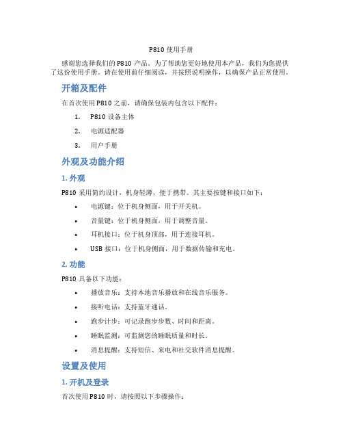
P810使用手册感谢您选择我们的P810产品。
为了帮助您更好地使用本产品,我们为您提供了这份使用手册。
请在使用前仔细阅读,并按照说明操作,以确保产品正常使用。
开箱及配件在首次使用P810之前,请确保包装内包含以下配件:1.P810设备主体2.电源适配器3.用户手册外观及功能介绍1. 外观P810采用简约设计,机身轻薄,便于携带。
其主要按键和接口如下:•电源键:位于机身侧面,用于开关机。
•音量键:位于机身侧面,用于调整音量。
•耳机接口:位于机身顶部,用于连接耳机。
•USB接口:位于机身侧面,用于数据传输和充电。
2. 功能P810具备以下功能:•播放音乐:支持本地音乐播放和在线音乐服务。
•接听电话:支持蓝牙通话。
•跑步计步:可记录跑步步数、时间和距离。
•睡眠监测:可监测您的睡眠质量和时长。
•消息提醒:支持短信、来电和社交软件消息提醒。
设置及使用1. 开机及登录首次使用P810时,请按照以下步骤操作:1.将P810靠近手机,开启手机的蓝牙功能。
2.在手机上搜索到P810设备,点击连接。
3.进入P810设置界面,根据提示完成登录。
2. 功能设置进入P810设置界面后,您可以根据个人需求调整以下功能:•音乐播放:选择本地音乐或在线音乐服务。
•电话功能:开启或关闭蓝牙通话功能。
•运动模式:选择跑步、步行或骑行等运动模式。
•睡眠监测:开启或关闭睡眠监测功能。
•消息提醒:设置短信、来电和社交软件的消息提醒。
3. 充电及续航P810使用内置可充电锂电池,可通过电源适配器充电。
充电时,请将电源适配器插入USB接口,指示灯亮起表示正在充电。
充电完成后,指示灯熄灭。
P810的续航时间如下:•音乐播放:约12小时•通话:约4小时•运动模式:约6小时故障排除如果您在使用过程中遇到问题,可以尝试以下方法解决:1.检查设备是否已充足电量。
2.确保手机蓝牙功能已开启。
3.重新连接手机和P810设备。
4.重启P810设备。
如果问题仍无法解决,请联系我们的客服支持。
810脱毛说明书中文版

2.2.1 电路安全1,半自动化的电路闸位于操作仪表盘,保护系统因电负荷过重跳闸。
要想恢复正常操作举起电路闸手柄重启系统。
2,软件保护,有电子狗自动检测。
3,附属机头的自动检测。
4,电路回路的自动检测。
2.2.2. 激光安全1,封闭的几何光导装置用来发射激光到治疗区。
光仅通过光导装置的前面发出2,系统掺入了安全的遥控连接装置,连接入门的外部连接到治疗室,安装后,入门是开启的情况下系统不能正常操作。
3,必要时紧急关闭安全钮会加速关闭系统,停止操作。
5,激光发射只有在脚踏和机头手柄同时按下时起作用,手柄可防止无意识的激光散射。
6,一旦系统启动就有水循环给机器降温。
7,水的流动和温度会有调控,减少机头过热的风险。
如果水流停止或水温达到或超过40℃都将发射不出激光。
8,系统配备有气流控制的脚踏便于使用,以减少短路的风险2.3治疗室治疗时必须粘贴危险标志,室内不应有任何反射物,如镜子,必须做好防护,必要时戴眼罩。
2.4.1预防措施必须熟读本手册,要保持机头清洁,不可通过拉机头手柄拖动机器。
2.4.2注意事项1,不用的时候把系统关闭2.,没人看护的情况下,不要把系统设在待机模式3,没经过培训的人员不准开机4,不要拉动脚踏或机头手柄,除非安全的指向特定的目标5,系统做维护时,不要开动系统。
2.5.1烧伤风险该机器激光波长是810nm,人眼是不可视的,可能引起Ⅲ度烧伤2.5.2 直接和间接的激光暴露风险所有在治疗室内的人都应做好防护,操作者和客人尽可能都戴眼罩,即使客人带了眼罩也要嘱咐其闭眼,如果客人不能带眼罩必须戴一个不透明的东西做好防护,如果治疗区域非常靠近眼睛请戴上角膜保护板。
2.5.4激光吸收后会增加吸收体的温度,要预防烧伤风险,系统不适合在有氧气等可燃性气体存在的情况下使用,不要在有酒精、汽油、甚至溶剂的情况下使用。
皮肤消毒时不应使用可燃物质如酒精或丙酮,必要时可使用肥皂或水来清洁,如果使用酒精的话,必须完全干燥后再操作。
Parker Hannifin 安装、操作与维护指南 - Series 810 角度体双向阀门说明书
FLUID CONTROL DIVISIONParker Hannifin Corporation95 Edgewood AvenueNew Britain, CT 06051Telephone (860) 827-2300IOM SERIES 810GENERAL SAFETY INSTRUCTIONS BEFORE INSTALLATIONFAILURE OR IMPROPER SELECTION OR IMPROPER USE OF THE PRODUCTS AND/OR SYSTEMS DESCRIBED HEREIN OR RELATED ITEMS CAN CAUSE DEATH, PERSONAL INJURY AND PROPERTY DAMAGE.This document and other information from Parker Hannifin Corporation, its subsidiaries and authorized distributors provide product and/or system options for further investigation by users having technical expertise. It is important that you analyze all aspects of your application, including consequences of any failure, and review the information concerning the product or system in the current product catalog. Due to the variety of operating conditions and applications for these products or systems, the user, through its own analysis and testing, is solely responsible for making the final selection of the products and systems and assuring that all performance, safety and warning requirements of the application are met.The products described herein, including without limitation, product features, specifications, designs, availability and pricing, are subject to change by Parker Hannifin Corporation and its subsidiaries at any time without notice.Carefully read installation, operation and maintenance procedures prior to installing or servicing valve.Do not use valve as a safety shut-off valve when making repairs.Do not install a valve before depressurizing system down to atmospheric pressure.Care must be taken to ensure that the valve materials selected are suitable for the media being handled. Parker assumes no liability for damage caused by improper material selection in the case of corrosion from aggressive media.Caution: Do not, at any time, make any alteration or modifications to any angle body valves without the express and written approval of Parker’s Fluid Control Division.DESCRIPTIONThese valves are 2-way valves. The product line contains both normally closed (N.C.) and normally open (N.O.) valves in a bronze and stainless construction. The valves can be actuated pneumatically or hydraulically. The pilot operated models require a minimum operating pressure differential to ensure valve operation.Pilot valves may be ordered with either NEMA 2, 4, 4X integrated coils for ordinary locations or NEMA 4, 4X, 7, and 9 for hazardous locations: Divisions I and II; Class I, Groups A, B, C, and D; Class II, Groups E, F, and G.PRINCIPLES OF OPERATION2-way SERIES 810 - NORMALLY CLOSED VALVESThe angle seat valve is kept closed by a spring which presses against a piston and piston rod forcing the seating seal tightly against the valve seat. When pressure is applied to the actuator pilot connection, the piston, piston rod and thus the seating seal are raised opening the valve.The valve tightly closes when pressure is removed from the pilot connection.The maximum permitted angle body valve pressure and pilot valve pressure and temperature ranges are described on the valve nameplate.2-way SERIES 810- NORMALLY OPEN VALVESThe angle seat valve is kept open by a spring which presses upward on a piston and piston rod forcing the seating seal off the valve seat. When pressure is applied to the actuator pilot connection, the piston, piston rod and thus the seating seal are driven down tightly closing the valve.The valve opens when pressure is removed from the pilot connection.The maximum permitted angle body valve pressure and pilot valve pressure and temperature ranges are described on the valve nameplate.CAUTION: A minimum pilot operating pressure differential is required for proper angle valve operation.Installation InstructionsMounting position and pressure limits: Valves can be mounted directly on piping and are designed to operate in any position. The valves may be installed in any line regardless of the direction in which the line runs. However, for optimum life and performance the valves should be mounted vertically upright so as to minimize wear and reduce the possibility of foreign matter accumulating inside the stem area.Pilot valve line pressure, voltage and frequency must conform to nameplate rating. Allow adequate clearance above valve for removal of coil.WARNING: The actuator is spring loaded. Depressurize system and turn off electrical power to the pilot valve before attempting repair. The coil must not be energized unless it is installed on the valve. Otherwise, the coil will overheat and burn out.Failure to depressurize the system could result in injury. Dismantle the actuator circle clip exclusively with the appropriate tools provided in the repair kit only. Follow the instructions provided in the repair kit.CAUTION: The valve body need not be removed from the line. When dismantling the actuator assembly, it may be necessary to provide proper support to prevent the valve from rotating thereby causing damage to piping.Where the valve is to be removed from the piping system, the pipeline must be drained completely before removing the valve especially with hazadous or aggressive media that can be hazardous to health.Installation StepsInstallation must be done according to all applicable Safety Codes and Standards and by qualified personnel.Inspect valve prior to installation. Damaged valves or actuators must not be installed.Ensure that the valves are installed whose pressure class, line pressure, type of connection and connection dimensions correspond to the usage conditions. WARNING: Do not install a valve whose permitted pressure / temperature ratings are inadequate to meet the operating conditions.Threaded connections are the most common. ANSI flanges, welded ends and tri-clamps are also available. Piping: Remove any protective enclosures from the body ports and connect line pressure to the inlet port of the valve. An arrow on the body indicates direction of flow. Use of Teflon tape, thread compound or sealant is permissible, but should be used sparingly to male pipe threads only. Connect outlet line to the opposite port. Ports should not be subjected to excessive torque by use of an oversized wrench, wrench extension or by impacting the wrench handle. Do not use the valve to “stretch” or “align” the ing the pipe to close a large gap can distort the valve or at least stress it unduly, and possibly cause it to malfunction, or the threaded ports may be damaged or stripped.Flanges: For flanged mounted valves, follow applicable ANSI, DIN, JIS specifications for bolting and torque recommendations. The bolt should pass first through the mounting flange before engaging the valve flange. Allow proper spacing for installing the valve. Do not use the valve to “stretch” or “align” the pipe. Using flange bolts to close a large gap can distort the valve or at least stress it unduly, and possibly cause it to malfunction, or the bolts may be damaged or stripped.The flange endings on the pipeline must align with the connection flanges on the valve and the faces must be parallel. Flanges which are out of alignment or not parallel may result in unacceptable stresses in the pipeline during installation and could thereby damage the valve.Welding: Care should be taken when soldering connections to avoid damage to synthetic internal parts. If pipeline welding is to be performed, care must be taken to ensure the cleanliness of both joints. It is recommended that the flame be directed away from the valve body. Cool body with a wet cloth or heat sink on the extensions at the body to prevent overheating while soldering.Actuation ConnectionConnecting the actuation unit to the control.A 3-way pilot valve is required to connect the control pressure for actuator functionality. For actuator types: Actuators with springs: Connect the control pressure to the inlet of the pilot valve and the outlet of the pilot valve to the threaded connection on the actuator.Double-acting actuators: Connect the control pressure line for “off” to the threaded connection on top of the actuator head. Connect the control pressure line for “on”to the threaded connection on the bottom of the actuator head.Actuators with positioners: Connect in accordance with supplied terminal plan.Pressure Testing and Valve FunctioningIt is recommended that newly installed pipeline systems first be flushed thoroughly to wash out all foreign matter.The test pressure of an open valve must not exceed 1.5 times the maximum rated pressure of the angle body valve. The test pressure of a closed valve must not exceed 1.1 times the maximum rated pressure of the angle body valve.Normal Operation and MaintenanceThe angle body pneumatic valves are operated by pneumatic control signals. The valves do not require regular maintenance work. While the valves are design to operate over millions of cycles, it is recommended that valves be rebuild every 2 million cycles to ensure optimum quality performance.During routine system checks, no leakage should be found in the valve. If unacceptable leakage occurs, reference “Troubleshooting” section for recommended solutions.If a valve is to be removed from a pipeline carrying hazardous media, the parts of the valve in contact with the hazardous media must be properly cleaned and decontaminated before repairs are performed.Note: Depending on service conditions, fluid being used, filtration, and lubrication, it may be required to periodically clean and/or replace worn components.CAUTION:Do not expose plastic or elastomeric materials to any type of commercial cleaning fluid. Parts should be cleaned with a mild soap and water solution. Replacement Parts: When ordering replacement parts kits, specify valve number and voltage from nameplate. Parts kits are available for each valve. Parts included in each kit are marked with an asterisk (*). See exploded views.REFERENCE CROSS SECTION DRAWINGS! Pilot Valve Installation Instructions Optional if pre-installed.These valves are 3-way, direct operated models. The brass versions are offered for multipurpose functionality for normally closed or normally open requirements.The stainless versions are offered in separate normally closed (N.C.), normally open (N.O.) versions.Valves may be ordered with either NEMA 2, 4, 4X integrated coils for ordinary locations or NEMA 4, 4X, 7, and 9 for hazardous locations: Divisions I and II; Class I, Groups A, B, C, and D; Class II, Groups E, F, and G. Media filtration: For protection of the pilot control valve, install a suitable strainer or filter in the inlet side as close to the valve as possible. Dirt or foreign material in the media may cause excessive leakage, wear, or in exceptional cases, malfunction. Clean periodically depending on service conditions.Lubrication: Lubrication is not required although air line lubrication will substantially increase valve life.Electrical connection: Electrical supply must conform to nameplate rating. Connect coil leads or terminals to the electrical circuit using standard electrical practices in compliance with local authorities and the National Electrical Code.Do not power coil until it has been fitted and the retaining washer and nut have been installed to prevent possible coil damage from overheating.WARNING: Turn off electrical power before connecting pilot control valve to the power source.WARNING:Valves to be installed in Hazardous Locations, must be outfitted with Hazardous Location coils only. Verify nameplate data and coil part number before installing the valve.If the coil assembly is located in an inconvenient orientation, it may be reoriented to facilitate installation. Loosen coil assembly nut, rotate coil assembly to desired position, then retighten the nut with an input torque of 43-53 in-lbs.MANUAL BYPASS OPTIONAL FEATURENote: Pilot valve manual bypass is an option. The manual bypass operator allows manual operation when desired or during an electrical power outage.COIL ASSEMBLYASSEMBLY INSTRUCTIONS FOR ALL COIL TYPESPosition coil (as described below) on the sleeve, install valve identification plate on top of coil, slide the wave washer over the sleeve and tighten coil assembly nut with an input torque of 43-53 in-lbs.DIN Coil and various cable option terminations: Loosen cable screw and remove plastic housing from DIN coil. Do not remove the gasket from the DIN spades on the coil. Separate the plastic block from the housing with a small screwdriver to expose the electrical terminations. Feed the lead wires through the DIN connector housing and attach them to the appropriate screw terminal. Snap the plastic block back into place. Replace the plastic housing onto the DIN spades and tighten the screws. To secure the housing and coil together, apply 20 to 30 in-lbs.Conduit Coil with 1/2” NPT connection: Conduit coils are available with either NEMA 2, 4, 4X integrated coils for ordinary locations or NEMA 4, 4X, 7, and 9 for hazardous locations: Divisions I and II; Class I, Groups A, B, C, and D; Class II, Groups E, F, and G.Use suitable electrical cabling and conduit materials and components meeting applicable NEMA recommendations. Coil/enclosure temperature: The pilot control valves are supplied with coils designed for continuous duty service. Normal free space must be provided for proper ventilation. When the coil is energized continuously for long periods of time, the coil assembly will become hot. The coil is designed to operate permanently under these conditions. Smoking and/or odor of burning coil insulation will indicate any excessive heating.For the maximum valve ambient conditions, as well as the fluid temperatures, check the valve part number on the nameplate and refer to the catalog to determine the maximum temperatures.TROUBLE SHOOTINGPROBLEM PROCEDUREAngle Body Valve fails to operate. 1. Check that pilot air supply is properly connected.2. Verify that pilot air supply meets the minimum pressure required toactuate the specific angle valve model number.3. Check pilot control valve functionality. Make sure that pressurecomplies with pilot control valve nameplate rating and pressure issupplied to actuator head through the output port of the pilot valve.4. Check pilot control valve electrical supply with voltmeter. Voltage mustagree with nameplate rating.5. If supply voltage is too low, locate and correct cause of low voltage.Supply voltage should exceed 85% of rated voltage.6. Check coil with ohmmeter for shorted or open coil.Angle Body Valve fails to close (normally closed valve).1. Check Angle Body Valve for functionality.2. Verify that pilot valve is vented from valve actuator.3. Check pilot control valve functionality. Make sure pilot valve closeseliminating pressure to the actuator head.4. If the pilot control valve works properly, it will be necessary todisassemble angle body valve. WARNING: following all caution and safety precautions prior to Disassembly.Angle Body Valve fails to close (normally open valve).1. Check Angle Body Valve for functionality.2. Check that pilot air supply is properly connected.3. Verify that pilot air supply meets the minimum pressure required toactuate the specific valve model number.4. Disassemble valve as per the Disassembly Instructions. Clean outextraneous matter. The plunger must be free to move without binding. 5. With coil energized, check power at coil wires. Power should be on. Ifpower is present, correct faulty contacts or wiring.External leakage at sleeve flange. 1. Check that sleeve is torqued to 260-270 in-lbs.2. If leakage persists, it will be necessary to disassemble angle body valve.WARNING: following all caution and safety precautions prior toDisassembly. Remove sleeve and check O-ring seal for damage.Replace if defective.Internal Seating Seal Leakage 1. Check if the actuator has closed the valve 100 percent. Debris orcontamination can prevent full closure.2. Disassemble valve as per the Repair Kit Disassembly Instructions.WARNING: following all caution and safety precautions prior toDisassembly. It is recommended that all components included in therepair kit be installed to prevent future problems.3. Examine orifice in body for nicks. Damage may require a newreplacement valve.4. Inspect the seat sealing material for foreign matter or dirt accumulation.Worn sealing material requires replacement.Pilot Valve TroubleshootingTROUBLE SHOOTINGPROBLEM PROCEDUREValve coil burn-out 1. Continuous high voltage greater than 10% of rated voltage could resultin coil failure. Locate and correct cause of high voltage.2. Disassemble valve as per the Disassembly Instructions. Check forforeign material lodged in valve. Clean out extraneous matter. Theplunger must be free to move without binding.3. Check electrical wiring installation.4. Valve located in high ambient temperature. Ventilate or isolate areafrom high temperatures. May require valve relocation to lowertemperature area.Valve is sluggish or inoperative – electrical supply and pressure check out.1. Disassemble valve as per the Disassembly Instructions. Clean outextraneous matter. The plunger must be free to move without binding.2. Check all springs, if broken, replace.External leakage at manual bypass stem (where available).1.Disassemble manual stem in valve per the Disassembly Instructions.Inspect components for damage. Replace o-ring if necessary.DECLARATIONParker’s Fluid Control Division certifies its valve appliance products complies with the essential requirements of the applicable European Community Directives. We hereby confirm that the appliance has been manufactured in compliance with the applicable standards and is intended for installation in a machine or application where commissioning is prohibited until evidence has been provided that the machine or application is also in compliance with EC directives.The data supplied in the Parker catalogs and general Installation, Operating & Maintenance Instructions are to be consulted and pertinent accident prevention regulations followed during product installation and use. Any unauthorized work performed on the product by the purchaser or by third parties can impair its function and relieves Parker Hannifin of all warranty claims and liability for any misuse and resulting damage.The angle body valve family complies with European Directive 97/23/EC in accordance with Annex II, category II, Group 2, module A1.A separate Declaration of Conformity or Manufacturer’s declaration is available upon request. Please provide valve identification numbers and order serial numbers of products concerned.。
BackBeat GO 810系列耳机用户指南说明书
BackBeat GO 810 Series User GuideContentsPair3Get Paired3Pair second device3Pair to Mac3Charge4Charge4The basics5Headset overview5Power on/off5Play/pause music5Track selection5Activate voice assistant5Make/Take/End Calls6Mute 6ANC6Set EQ6Find your headset6Support712••312Select “PLT BBGO800 Series” in your device's Bluetooth Settings.If your Mac is Bluetooth enabled, you can pair your headset to it.1Place your headset in pair mode (slide and hold the power button towards the Bluetooth icon). Youwill hear "pairing" and the LEDs will flash red and blue.2On your Mac, choose Apple menu > System Preferences > Bluetooth .3Click Set Up New Device or "+", select "PLT BBGO800 series stereo" and follow the onscreeninstructions.PairGet PairedPair second devicePair to MacIt takes up to 120 minutes to fully charge your headset. The LEDs turn off once charging iscomplete.headset. The headset must be in an idle state.Your headset has up to 22 hours of listening time with ANC on and 28 hours with ANC off.ChargeChargeVolume up Volume down Track forward Play/pause music Track backward Call button Siri, Google Now Voice-enabled assistant Bluetooth pair button Power on/off Headset LEDs Mute/unmute EQ settings Slide the switch to power on or off.Tap the Play/pause button.Tap the Forward button or Back button to control the track selection.If your smartphone has a voice-enabled assistant, press and hold the Play/pause button for 2seconds and wait for the phone prompt.The basicsHeadset overviewPower on/offPlay/pause musicTrack selectionActivate voice assistantAnswer or end a call Tap the Play/pause button.Decline a call Press and hold the Play/pause button for 2 seconds.Call back last call (smartphone)To dial the last number you dialed, double-tap the Play/pause button.While on an active call, tap the EQ/Mute button.Active Noise Canceling (ANC) reduces external noise and enhances your music and sound quality.1Press and hold the volume up and down buttons for two seconds to turn ANC on or off.2You can further customize ANC in the BackBeat app by chooosing:•Low: recommended for office •High: recommended for airplane Customize your audio and cycle through the EQ modes by tapping the EQ button. You can also change the EQ thru the BackBeat app.•Balanced (default) Tune frequencies to sound best across multiple genres of music with balanced lows, mids and highs.•Bright Boost treble frequencies to enhance the detail and clarity of music and make speech-based content more intelligible.Most headsets are found under car seats, in pockets or on a messy desk. For less obvious locations, locate your headset by sending a tone to find it.1Download the BackBeat app by visiting the Apple Store, Google Play or /software .2Locate your lost headset by using Find MyHeadset within the app.Make/Take/End CallsMuteANCSet EQFind your headsetSupportNEED MORE HELP?/supportPlantronics, Inc.Plantronics B.V.345 Encinal Street Santa Cruz, CA 95060 United States Scorpius 171 2132 LR Hoofddorp Netherlands© 2018 Plantronics, Inc. BackBeat and Plantronics are trademarks of Plantronics, Inc. registered in the US and other countries, and Plantronics Hub is a trademark of Plantronics, Inc. Bluetooth is a registered trademark of Bluetooth SIG, Inc. and any use by Plantronics, Inc. is under license. All other trademarks are the property of their respective owners.Patents pending.212987-06 (08.18)。
Luxul XAP-810产品说明书
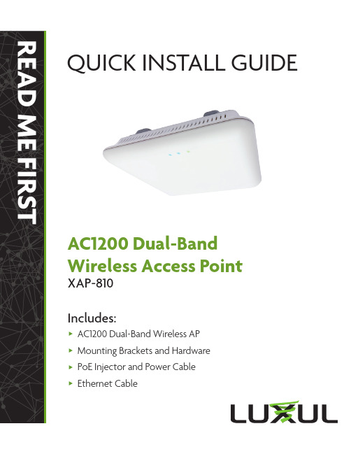
READ ME FIRST QUICK INSTALL GUIDEAC1200 Dual-BandWireless Access PointXAP-810Includes:AC1200 Dual-Band Wireless APMounting Brackets a nd HardwarePoE Injector and P ower CableEthernet CableREAD ME FIRST - CONTROLLER COMPATIBILITY This XAP-810 is compatible with the Luxul Wireless Controller for fast, easy configuration and deployment of wireless networks with multiple APs.n Note: If you’ll be using this AP with a Wireless Controller, refer to the Quick Install Guide included with the Wireless Controller forsetup instructions.AP SETUP AND CONFIGURATION1Physical InstallationThe XAP-810 access point is designed for simple and efficient installation and can be located one of three ways. First, the included mount is designed to attach directly to several different regions’ standard electrical boxes. Second, the XAP-810 may be mounted on a ceiling or wall without a box by using the included mount as a guide to mark attachment locations. Finally, the XAP-810 can be placed on a flat surface by attaching the included rubber feetto the mount.c Caution: Attach the rubber feet to the mount and attach the mount tothe AP for flat surface placement to avoid overheating and failure.X Single Access Point Placement: Because the signal generated by theXAP-810 is omnidirectional, the unit should be located as near as possible to the center of the desired coverage area.XAP-810 Single AP Coverage PatternXAP-810 Multiple AP Coverage and OverlapNext, connect an Ethernet cable from your Router or Switch to the Data IN port on the PoE Injector. Finally, connect the AC cord to the includedPoE Injector, then to the AC outlet.n Note: Luxul recommends at least Cat-5e unshielded twisted pair (CAT5e UTP) cabling. To ensure best performance at 1000 Mbps, useCAT6 UTP.PoE Injector SetupX Data In: Connect an Ethernet cable from your router or switch to the Data In port of the included PoE Injector.X Data & PWR Out: Connect an Ethernet cable from the Data & PWR Out port of the included PoE Injector to the PoE Port of the XAP-810.X AC Power: Connect the included AC Cord to the Power Input of the Included Injector first and then to the AC outlet.PoE injector3 Preparing for AccessIP AddressingIf the XAP-810 is connected to a network with a 192.168.0.X address scheme, and your computer shares a similar address on the same network, you can skip to the next step, Access and Setup.If your network uses an address scheme other than 192.168.0.X, you’ll needto set a temporary static IP address on the computer you’re using for config-uration. To do so, set the IP address of your computer to any address in the 192.168.0.X range other than 192.168.0.10.Once you’re finished configuring the AP, you can return your computer’s IP configuration to normal, typically “Obtain Automatically/DHCP.”n Note:V isit /ip-addressing to learn more aboutchanging your computer’s IP address and getting connected.4 Access and SetupGetting ConnectedX Connecting Via an Ethernet Device: Use Ethernet cable to connectyour computer to the PoE switch or PoE injector to which the XAP-810 is connected. Ethernet is the preferred method of connection.X Connecting Via a Wireless Device: Connect your client device to the XAP-810 default wireless network named Luxul_XAP810 or Luxul_XAP810_5G. The wireless network will run in Open Security mode, so no passphrase is required until Wireless Security is configured.Logging InTo access the AP’s web configuration, open your web browser and enter the AP’s default 192.168.0.10 IP address in the address field. Log in to the AP using the default user name and password:Default IP: 192.168.0.10Username: adminPassword: adminn Note:I f another device on your network shares the 192.168.0.10 address, you’ll need to temporarily reassign or remove that device whileyou configure the XAP-810.n Note:T he XAP-810 is not a router and will need to be connected to a network with a router in order to deliver Internet access.5 Hardware OperationLED IndicatorsEnclosure: If the green Power LED is on, the XAP-810 is powered and working. If the Power LED is OFF, the AP is not receiving power or the LED has been turned off in the AP’s web interface. If the green Power LED is blinking, the XAP-810is booting. The two blue LEDs indicate indicate each of the 2.4GHz and 5GHz networks are configured and broadcasting.XAP-810 LED’sPoE Injector: If the PWR LED is On, Power is Connected to the injector. If the PWR LED is Off, the injector is not receiving power.Reset ButtonThe Reset button is located underneath the mount andmarked RESET. It may be used to reboot the AP or to restorefactory default settings.Reboot the AP: With the XAP-810 powered on, simply pressand release the Reset button.Restore Factory Defaults: With the XAP-810 powered on, press and hold the Reset button for 10 seconds, then release the button and the XAP-810 will restore factory defaults and reboot.c CAUTION:H olding the Reset button for more than a few secondswill restore the AP to factory default and remove anycustom configuration.Sales801-822-5450 ***************Technical Support 801-822-5450*****************LUX-QIG-XAP-810-v3 07171703 Copyright and Trademark Noticesonly exists for equipment, circuits and subsystems contained in this or any Luxul product.registered trademarks are property of their respective holders.。
Whelen Engineering Model 810 光标警报灯安装指南说明书
©1996 Whelen Engineering Company Inc.Form No.13110E (091801)Installation Guide:Model 810 Warning LightFor warranty information regarding this product, visit /warranty•Proper installation of this product requires the installer to have a good understanding of automotive electronics, systems and procedures.•Whelen Engineering requires the use of waterproof butt splices and/or connectors if that connector could be exposed to moisture.•Any holes, either created or utilized by this product, should be made both air- and watertight using a sealant recommended by your vehicle manufacturer.•Failure to use specified installation parts and/or hardware will void the product warranty.•If mounting this product requires drilling holes, the installer MUST be sure that no vehicle components or other vital parts could be damaged by the drilling process. Check both sides of the mounting surface before drilling begins. Also de-burr the holes and remove any metal shards or remnants. Install grommets into all wire passage holes.•If this manual states that this product may be mounted with suction cups, magnets, tape or Velcro®, clean the mounting surface with a 50/50 mix of isopropyl alcohol and water and dry thoroughly.•Do not install this product or route any wires in the deployment area of your air bag. Equipment mounted or located in the air bag deployment area will damage or reduce the effectiveness of the air bag, or become a projectile that could cause serious personal injury or death. Refer to your vehicle owner’s manual for the air bag deployment area. The User/Installer assumes full responsibility to determine proper mounting location, based on providing ultimate safety to all passengers inside the vehicle.•For this product to operate at optimum efficiency, a good electrical connection to chassis ground must be made. The recommendedprocedure requires the product ground wire to be connected directly to the NEGATIVE (-) battery post (this does not include products that use cigar power cords).•If this product uses a remote device for activation or control, make sure that this device is located in an area that allows both the vehicle and the device to be operated safely in any driving condition.•Do not attempt to activate or control this device in a hazardous driving situation.•This product contains either strobe light(s), halogen light(s), high-intensity LEDs or a combination of these lights. Do not stare directly into these lights. Momentary blindness and/or eye damage could result.•Use only soap and water to clean the outer lens. Use of other chemicals could result in premature lens cracking (crazing) and discoloration. Lenses in this condition have significantly reduced effectiveness and should be replaced immediately. Inspect and operate this product regularly to confirm its proper operation and mounting condition. Do not use a pressure washer to clean this product.•It is recommended that these instructions be stored in a safe place and referred to when performing maintenance and/or reinstallation of this product.•FAILURE TO FOLLOW THESE SAFETY PRECAUTIONS AND INSTRUCTIONS COULD RESULT IN DAMAGE TO THE PRODUCT OR VEHICLE AND/OR SERIOUS INJURY TO YOU AND YOUR PASSENGERS!A u t o m o t i v e : Warnings to InstallersWhelen’s emergency vehicle warning devices must be properly mounted and wired in order to be effective and safe. Read and follow all of Whelen’s written instructions when installing or using this device. Emergency vehicles are often operated under high speed stressful conditions which must be accounted for when installing all emergency warning devices. Controls should be placed within convenient reach of the operator so that they can operate the system without taking their eyes off the roadway. Emergency warning devices can require high electrical voltages and/or currents. Properly protect and use caution around live electrical connections.Grounding or shorting of electrical connections can cause high current arcing, which can cause personal injury and/or vehicle damage, including fire. Many electronic devices used in emergency vehicles can create or be affected by electromagnetic interference. Therefore, after installation of any electronic device it is necessary to test all electronic equipment simultaneously to insure that they operate free of interference from other components within the vehicle. Never power emergency warning equipment from the same circuit or share the same grounding circuit with radio communication equipment. All devices should be mounted in accordance with the manufacturer’s instructions and securely fastened to vehicle elements of sufficient strength to withstand the forces applied to the device. Driver and/or passenger air bags (SRS) will affect the way equipment should be mounted. This device should be mounted by permanent installation and within the zones specified by the vehicle manufacturer, if any. Any device mounted in the deployment area of an air bag will damage or reduce the effectiveness of the air bag and may damage or dislodge the device. Installer must be sure that this device, its mounting hardware and electrical supply wiring does not interfere with the air bag or the SRS wiring or sensors. Mounting the unit inside the vehicle by a method other than permanent installation is not recommended as unit may become dislodged during swerving; sudden braking or collision. Failure to follow instructions can result in personal injury. Whelen assumes no liability for any loss resulting from the use of this warning device. PROPER INSTALLATION COMBINED WITH OPERATOR TRAINING IN THE PROPER USE OF EMERGENCY WARNING DEVICES IS ESSENTIAL TO INSURE THE SAFETY OF EMERGENCY PERSONNEL AND THE PUBLIC.Warnings to UsersWhelen’s emergency vehicle warning devices are intended to alert other operators and pedestrians to the presence and operation of emergency vehicles and personnel. However, the use of this or any other Whelen emergency warning device does not guarantee that you will have the right-of-way or that other drivers and pedestrians will properly heed an emergency warning signal. Never assume you have the right-of-way. It is your responsibility to proceed safely before entering an intersection, driving against traffic, responding at a high rate of speed, or walking on or around traffic lanes. Emergency vehicle warning devices should be tested on a daily basis to ensure that they operate properly. When in actual use, the operator must ensure that both visual and audible warnings are not blocked by vehicle components (i.e.: open trunks or compartment doors), people, vehicles, or other obstructions. It is the user’s responsibility to understand and obey all laws regarding emergency warning devices. The user should be familiar with all applicable laws and regulations prior to the use of any emergency vehicle warning device. Whelen’s audible warning devices are designed to project sound in a forward direction away from the vehicle occupants. However, because sustained periodic exposure to loud sounds can cause hearing loss, all audible warning devices should be installed and operated in accordance with the standards established by the National Fire Protection Association.Safety FirstThis document provides all the necessary information to allow your Whelen product to be properly and safely installed. Before beginning the installation and/or operation of your new product, the installation technician and operator must read this manual completely. Important information is contained herein that could prevent serious injury or damage.WARNING: This product can expose you to chemicals including Methylene Chloride which is known to the State of California to cause cancer, and Bisphenol A, which is known to the State of California to cause birth defects or other reproductive harm. For more information go to .51 Winthrop RoadChester, Connecticut 06412-0684Phone: (860) 526-9504Internet: Salese-mail:*******************CustomerServicee-mail:*******************®ENGINEERING COMPANY INC.Installation:There are two ways to mount the 810 lighthead, each offering it’s own benfits:•Secured to vehicle using supplied #10 x 1” sheet metal screws.•Secured to vehicle using an industry-strength, double-sided adhesive tape, like Scotch™ brand VHB™ model 4956 foam tape.This manual will outline the first procedure.1.Position the 810 lighthead in it’s approximatemounting location. Make sure that the 810 will not interfere with any existing equipment. Also be aware of any and all items on the opposite side of the mounting surface to prevent any possible damage to existing components.2.Position the supplied mounting template on themounting location and temporarily secure it to the surface. Be sure the template is FLAT against the surface.Note:Before proceeding, place the reflector against the template and confirm that themounting holes on the template line upwith the actual mounting holes on thereflector.Note:Be sure the gasket is mounted with the drain holes on the bottom. Each gasket islabeled.ing a #27 drill bit, drill the mounting holes asshown on the template.4.The rectangle on the template represents therecommended location for the wiring hole. Drill a5/8” wire access hole any where within this rectangle. DO NOT DRILL OUTSIDE OF THIS AREA.5.Connect the RED wire to +12VDC and the WHITEwire to chassis ground. Fuse the RED wire at 7.5 amps.WARNING!All customer supplied wires that connect to the positive (+) terminal of the battery, must be sized to supply at least 125% of the maximum operating current, and fused “at the battery” to carry that load.6.After testing lamp operation, secure the reflector tothe vehicle with the supplied mounting screws.7.Mount the lens onto the reflector and secure withthe supplied lens screw.。
- 1、下载文档前请自行甄别文档内容的完整性,平台不提供额外的编辑、内容补充、找答案等附加服务。
- 2、"仅部分预览"的文档,不可在线预览部分如存在完整性等问题,可反馈申请退款(可完整预览的文档不适用该条件!)。
- 3、如文档侵犯您的权益,请联系客服反馈,我们会尽快为您处理(人工客服工作时间:9:00-18:30)。
小型企业、学校、SOHO 用户等接入 Internet
第3页
UTT Technologies
HiPER 810 智能宽带路由器/宽带网关
外观尺寸:230mm×140mm×44mm 重 量:1kg
工作环境: 温 度:0-40℃ 高 度:0-4000m 相对湿度:10-90%,不结露
电 源: 输入功率:最大 5W,正常 3W 交流电压(AC):180V~240V
第1页
UTT Technologies
HiPER 810 智能宽带路由器/宽带网关
支持按时间段进行带宽管理,实现了在网络繁忙的时候启用带宽管理,从而保证局域网所有用户都能合理 使用带宽;而在用户少、网络空闲的时候,则不进行带宽控制,从而方便网络管理员进行更新内部服务器 等网络维护工作,使得现有用户能够高速上网,保证了线路带宽的充分利用。
支持的协议: IP,TCP,ARP,UDP,ICMP,NAT,反向 NAT,DHCP,SNTP,触发式路由更新,TELNET,HTTP,
TFTP,PPP,SNMP,PPPoE,PAP,CHAP,SYSLOG
路由协议: 静态路由,动态路由 RIP I 和 RIP II
管理和配置: WEB UI,CLI,Xport HiPER Manager
支持配置文件备份与导入,可将 HiPER 当前配置文件保存到管理计算机,也可将备份的配置文件导入到 HiPER 中,节省重复配置的时间;支持 WEB、TFTP 多种升级方式,方便功能扩展。 提供标准的 SNMP 接口,可供远程 SNMP 服务器管理;并且,提供系统日志功能,可通过远程 SYSLOG 服务器记录。
支持最大 NAT 并发会话数限制,还可以分别限制由 TCP、UDP 或者 ICMP 协议构成的最大并发会话数, 可以有效防止用户使用 P2P 等海量下载软件过度占用带宽,还可以避免中毒主机过度浪费带宽,保证其他 主机运行正常。
用户管理
提供用户个性化管理功能,实现了百分之百的按需定制。针对用户的实际需求,每台内部主机都可以采取 不同的策略(可以任意限定某台 PC 可使用的带宽、NAT 会话数,是否禁止 QQ、MSN、P2P,等等),解 决了传统的分区管理不够灵活的问题。该功能不仅可以大大加强管理的灵活性,并在一定程度上降低了管 理员的工作量。
UTT Technologies
HiPER 810 智能宽带路由器/宽带网关
HiPER 810 智能宽带路由器/宽带网关
HiPER 810 智能宽带路由器/宽带网关是一款专为小型企 业、学校等机构以及对网络要求较高的 SOHO 用户接入 Internet 设计的宽带接入产品。
HiPER 810 使用艾泰科技自主研发的 ReOS 网络操作系统, 除具备智能 NAT、防火墙、带宽管理、IP/MAC 绑定、业务管 理等宽带路由器常见的功能之外,还具备性价比高、安全性强、 配置简单实用等突出特点,尤为一叹的是,它还提供了类似 WINDOS 风格的自动更新功能。
策略库
通过引入策略库,将复杂的多条策略当作一个策略库处理,再加上类似于 WINDOWS 风格的策略库自动 更新功能,不仅大大简化了配置的复杂度,还可以为用户免除很多烦琐的手工维护工作。针对 QQ、MSN、 P2P 等应用软件的频繁升级,艾泰科技公司技术人员会在第一时间收集相关信息,并及时提供最新版本的 策略库,避免用户的后顾之忧。
端口镜像
支持端口镜像,实时提供各端口的传输状况的详细资料,通过将各个端口的流量复制镜像端口,以便监管 部门进行监控,网管人员进行流量监控、性能分析和故障诊断。
网络监控
提供多种监控和诊断方式,可动态监控网络运行情况、用户上网行为,帮助网管人员快速定位和排除网络 故障,特别是能够实时发现网络异常以及异常主机,如感染病毒或发起攻击的主机。
支持 IP/MAC 地址绑定,过滤非法 IP 或 MAC 地址,方便设置上网黑名单和白名单。值得注意的是,HiPER 还支持 IP/MAC 地址全部绑定功能,只需一键操作,就可以一次性将所有动态 IP/MAC 地址对全部绑定; 再配合 ARP 广播和更新限制功能,就可以有效防止 HiPER 和局域网主机遭受 ARP 欺骗攻击了。
第2页
UTT Technologies
ห้องสมุดไป่ตู้
HiPER 810 智能宽带路由器/宽带网关
关键特性
支持 DSL,FTTX+LAN 和 Cable Modem 连接,特别适合光纤接入 LAN 口(4 个内置的交换式以太网口),1 个 WAN 口 LAN/WAN 支持正反线自适应,支持 10/100M 自适应 支持快速转发,吞吐量最高可达 150Mbps,最多 50K PPS 基于地址、协议和端口的包过滤 基于站点、URL 和关键字的应用层过滤 支持 NAT 会话数限制,可限制单机会话数 支持带宽管理,可限制单机带宽 支持 DHCP 服务器和客户端,支持 DHCP 手工绑定 支持 IP/MAC 绑定 支持 DDNS 支持 DNS 代理 支持端口镜像 支持时间段管理 支持网络时间同步 基于端口的 VLAN 支持 MSN 语音穿透 支持 UPnP 支持多个 L2TP/PPTP/IPSec 的 VPN 穿透
网管人员通过实时监测 CPU 利用率、内存利用率、NAT 表等关键系统资源,可以及时发现潜在的各种攻 击;通过实时查看各个接口的带宽,查看各个用户的上传/下载带宽以及 NAT 会话数,查看上传/下载带宽 排行榜和 NAT 会话数排行榜,能够快速定位网速慢、卡等网络异常。
配置和管理
提供友好的全中文 WEB 界面,直观易用、功能丰富,快速向导可帮助用户在短时间内完成初始配置;同 时还提供传统的 CLI 界面,功能更丰富;并且,两种方式下均支持通过 Internet 进行简便、安全的远程管 理。
防火墙功能
强大的防御内部/外部攻击能力,能有效防范 ARP 欺骗、端口扫描、DoS/DDoS 等网络攻击,防止冲击波、 震荡波、SQL 蠕虫等病毒攻击,最大程度地保证 HiPER 及网络的稳定性和安全性。 实现了基于源/目的 IP 地址、协议、端口、源/目的 MAC 地址的包过滤,基于 URL 和关键字的应用层过滤, 还可按时间段进行过滤。采用上述过滤技术的业务管理功能,不仅可以控制用户的上网权限和上网时段, 还能够保护内部网络免遭外来攻击。
通过引用防火墙策略库,不仅实现了单键设置 ARP 欺骗防御、DoS/DDoS 攻击防御、冲击波病毒防御等功 能;还实现了单键管制 QQ、MSN 等即时聊天软件的使用,单键管制 BT、电驴等常用 P2P 软件的使用, 大大简化了配置。
带宽管理
提供基于 CBT(Credit-Based Queuing)算法的带宽管理功能,可大大提高带宽利用率,并能有效抑制 BT、 迅雷、QQ 直播等 P2P 软件对带宽的滥用:对于正常上网的主机,HiPER 将允许它偶尔突破最大限速;相 反,对于长期使用 P2P 软件的主机,HiPER 将会减小它的带宽,使其对其他主机的影响降到最低。
第4页
智能 NAT
支持 NAPT、NAT 以及路由的混合使用,满足各种复杂的网络地址规划。支持 NAT 静态映射和 DMZ 主机, 向外提供 WWW、Telnet、FTP 等服务;支持 NAT Re-routing 和反向 NAT;提供 NAT ALG 功能,支持 FTP、 PPTP、IPSec ESP 等特殊应用协议。
