regiongrow冈萨雷斯图像处理源代码
冈萨雷斯数字图像处理10
四、边缘检测
Roberts采用两个模板来计算图像的梯度,如下图
-1 0 0 1 0 1 -1 0
水平梯度模板
垂直梯度模板
水平梯度为: Gx z9 z5 垂直梯度为: Gy z8 z6 2 2 1/ 2 梯度为: g Gx G y Roberts边缘检测器调用语法为: [g,t]=edge(f, ‘roberts’, T, dir); Roberts边缘检测器是最古老的边缘检测器之一, 常用于硬件计算中,既简单又快速
四、边缘检测
f Gx x 2 f f , 幅值为:f m ag(f) G 2 G x y G y y
虽然点检测和线检测算法都很简单,但边缘检测在 实际图像处理中更为常用。 边缘检测通常采用检测亮度的不连续性来实现,即 采用一阶导数和二阶导数来检测。 一阶导数一般用梯度来表示,公式为:
四、边缘检测
不同边缘检测方法的比较: f = imread(‘lp.bmp’); f=rgb2gray(f); [gsobel, t] = edge(f, ‘sobel’); figure, imshow(gsobel); [glog, t] = edge(f, ‘log’); figure, imshow(glog); [gcanny, t] = edge(f, ‘canny’); figure, imshow(gcanny);
1/ 2
(f / x) 2 (f / y ) 2
1/ 2
常用梯度的幅值表示梯度,近似为: f Gx G y 二阶导数用拉普拉斯算子来计算,公式为:
bound2im(b, M, N, x0, y0)冈萨雷斯图像处理的源代码
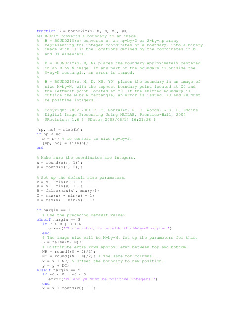
function B = bound2im(b, M, N, x0, y0)%BOUND2IM Converts a boundary to an image.% B = BOUND2IM(b) converts b, an np-by-2 or 2-by-np array% representing the integer coordinates of a boundary, into a binary % image with 1s in the locations defined by the coordinates in b% and 0s elsewhere.%% B = BOUND2IM(b, M, N) places the boundary approximately centered % in an M-by-N image. If any part of the boundary is outside the% M-by-N rectangle, an error is issued.%% B = BOUND2IM(b, M, N, X0, Y0) places the boundary in an image of % size M-by-N, with the topmost boundary point located at X0 and% the leftmost point located at Y0. If the shifted boundary is% outside the M-by-N rectangle, an error is issued. XO and X0 must % be positive integers.% Copyright 2002-2004 R. C. Gonzalez, R. E. Woods, & S. L. Eddins% Digital Image Processing Using MATLAB, Prentice-Hall, 2004% $Revision: 1.6 $ $Date: 2003/06/14 16:21:28 $[np, nc] = size(b);if np < ncb = b'; % To convert to size np-by-2.[np, nc] = size(b);end% Make sure the coordinates are integers.x = round(b(:, 1));y = round(b(:, 2));% Set up the default size parameters.x = x - min(x) + 1;y = y - min(y) + 1;B = false(max(x), max(y));C = max(x) - min(x) + 1;D = max(y) - min(y) + 1;if nargin == 1% Use the preceding default values.elseif nargin == 3if C > M | D > Nerror('The boundary is outside the M-by-N region.') end% The image size will be M-by-N. Set up the parameters for this.B = false(M, N);% Distribute extra rows approx. even between top and bottom.NR = round((M - C)/2);NC = round((N - D)/2); % The same for columns.x = x + NR; % Offset the boundary to new position.y = y + NC;elseif nargin == 5if x0 < 0 | y0 < 0error('x0 and y0 must be positive integers.')endx = x + round(x0) - 1;y = y + round(y0) - 1;C = C + x0 - 1;D = D + y0 - 1;if C > M | D > Nerror('The shifted boundary is outside the M-by-N region.') endB = false(M, N);elseerror('Incorrect number of inputs.')endB(sub2ind(size(B), x, y)) = true;。
数字图像处理课程设计报告(冈萨雷斯版)
1. 课程设计目的1、提高分析问题、解决问题的能力,进一步巩固数字图像处理系统中的基本原理与方法。
2、熟悉掌握一门计算机语言,可以进行数字图像的应用处理的开发设计。
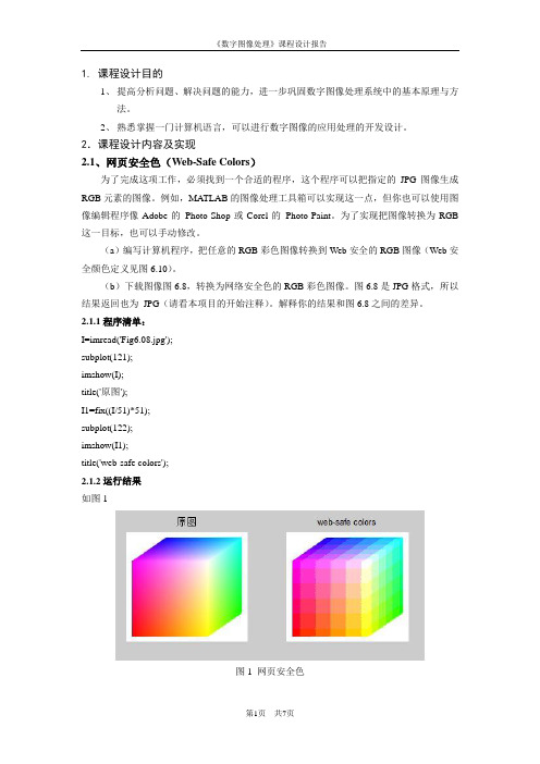
2.课程设计内容及实现2.1、网页安全色(Web-Safe Colors)为了完成这项工作,必须找到一个合适的程序,这个程序可以把指定的JPG图像生成RGB元素的图像。
例如,MATLAB的图像处理工具箱可以实现这一点,但你也可以使用图像编辑程序像Adobe的Photo-Shop或Corel的Photo-Paint。
为了实现把图像转换为RGB 这一目标,也可以手动修改。
(a)编写计算机程序,把任意的RGB彩色图像转换到Web安全的RGB图像(Web安全颜色定义见图6.10)。
(b)下载图像图6.8,转换为网络安全色的RGB彩色图像。
图6.8是JPG格式,所以结果返回也为JPG(请看本项目的开始注释)。
解释你的结果和图6.8之间的差异。
2.1.1程序清单:I=imread('Fig6.08.jpg');subplot(121);imshow(I);title('原图');I1=fix((I/51)*51);subplot(122);imshow(I1);title('web-safe colors');2.1.2运行结果如图1图1 网页安全色结果分析:结果图出现明显的方格,每个方格就是一个网页安全色,方格内的颜色一致。
原图则是普通的RGB,假使在原图的相同区域划分出和结果图相对应的方格,则此方格里的颜色是一个渐变的颜色,并非同一种颜色。
2.2、伪彩色图像处理(Pseudo-Color Image Processing )(a)实现图6.23的特性,你可以为输入图像指定两个范围的灰度值,然后你的程序将输出的RGB图像,它的像素有一个指定的颜色,对应于输入图像的一个范围的灰度级,RGB 图像中剩余的像素具有和输入图像相同的灰度。
数字图像处理(冈萨雷斯第三版)

左边的图象是图象处理技术 中常用来检验计算机算法的 实际效果的标准图象。 这幅图象的名称是lenna。它 是由一组数字组成的。原图象 的宽和高都是256个象素,每 象素有八位。它在BMP格式下 有约66K字节的大小。
.
1.1.2 图象技术和图象工程
• 数字图象处理的简史 数字图象的产生远在计算机出现之前。最早有电报传输的 数字图象。六、七十年代,随着计算机硬件的发展和快速 傅立叶变换算法的发现使得用计算机能够处理图象。八十 年代开始处理三维图象,九十年代以来,随着计算机性能 的大幅提高和广泛使用,图象处理技术已经涉及社会的各 个角落。图象逐渐在传播媒体中占据了主导地位,产生的 许多的新行业新商机。未来图象处理的发展是不可限量的。 数字图象处理属于计算机科学,但是它的90%依赖于数学。 从这个特点来看,对于本专业的学生来说,数字图象处理 技术是一个十分理想的发展方向。
.
图象文件的数据结构
一个完整的图象处理程序的基本功能有:打开图象文件、 显示图象、对图象文件进行指定的处理、存储图象文件。 由于图象文件比较大,通常需要在储存前进行压缩。所以 打开和存储图象文件涉及到文件的格式。
• 图象文件的格式 图像文件指包含图像数据的文件。文件内除图像数据本身 以外,一般还有图像的描述信息,以便图像的读取和显示。 表示图像常用矢量形式或光栅形式。 矢量形式中图像用一系列线段或线段的组合体来表示, 线段的灰度可以不同,组合体的各部分可用不同的灰度来 填充。矢量形式文件中有一系列的命令和数据,执行的结 果是画出图像来。
.
• 什么是图像工程?(广义的数字图像处理)
它是由图像处理、图像分析和图像理解三个系统所组 成。图像处理包括图像采集和从图像到图像的变换,以改 善主观的视觉效果和为图像分析和图像理解作初步的处理。 图像分析是从图像中取出感兴趣的数据,以描述图像中目 标的特点。图像理解是在图像分析的基础上研究各目标的 性质和相互关系,以得出图像内容的理解和对原场景的解 释。图像处理、图像分析和图像理解是处在从低到高的三 个不同的抽象程度上的过程。本课程着重于图像处理和分 析系统。
冈萨雷斯版数字图像处理常用的图像处理函数_百度文库
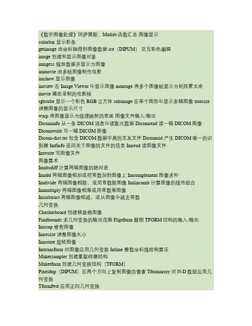
《数字图像处理》冈萨雷斯,Matlab函数汇总图像显示colorbar 显示彩条getimage 由坐标轴得到图像数据 ice(DIPUM)交互彩色编辑image 创建和显示图像对象imagesc 缩放数据并显示为图像immovie 由多帧图像制作电影imshow 显示图像imview 在Image Viewer中显示图像 montage 将多个图像帧显示为矩阵蒙太奇movie 播放录制的电影帧rgbcube 显示一个彩色RGB立方体 subimage 在单个图形中显示多幅图像 truesize 调整图像的显示尺寸warp 将图像显示为纹理映射的表面图像文件输入/输出Dicominfo 从一条DICOM消息中读取元数据 Dicomread 读一幅DICOM图像Dicomwrite 写一幅DICOM图像Dicom-dict.txt 包含DICOM数据字典的文本文件 Dicomuid 产生DICOM唯一的识别器 Imfinfo 返回关于图像的文件的信息 Imread 读图像文件Imwrite 写图像文件图像算术Imabsdiff 计算两幅图像的绝对差Imadd 两幅图像相加或把常数加到图像上 Imcomplement 图像求补Imdivide 两幅图像相除,或用常数除图像 Imlincomb 计算图像的线性组合Immultiply 两幅图像相乘或用常数乘图像Imsubtract 两幅图像相减,或从图像中减去常数几何变换Checkerboard 创建棋盘格图像Findbounds 求几何变换的输出范围 Fliptform 颠倒TFORM结构的输入/输出Imcrop 修剪图像Imresize 调整图像大小Imrotate 旋转图像Imtransform 对图像应用几何变换 Intline 整数坐标线绘制算法Makersampler 创建重取样器结构Maketform 创建几何变换结构(TFORM)Pixeldup(DIPUM)在两个方向上复制图像的像素 Tformarray 对N-D数组应用几何变换Tformfwd 应用正向几何变换Tforminv 应用反向几何变换Vstformfwd(DIPUM)可视化正向几何变换图像匹配Cpstruct2pairs 将CPSTRUCT转换为有效的控制点对 Cp2tform 由控制点对推断几何变换Cpcorr 使用互相关校准控制点位置Cpselect 控制点选择工具Normxcorr2 归一化二维互相关像素值及统计Corr2 计算二维相关系数Covmatrix(DIPUM)计算向量族的协方差矩阵 Imcontour 创建图像数据的轮廓线Imhist 显示图像数据的直方图Impixel 确定像素的彩色点Improfile 计算沿着线段的像素值横截面Mean2 计算矩阵元素的均值Pixval 显示关于像素的信息Regionprops 测量图像区域的属性Statmoments(DIPUM)计算一幅图像直方图的统计中心距 Std2 计算矩阵元素的标准偏差图像分析(包括分割、描述和识别)Bayesgauss(DIPUM)高斯模式的贝叶斯分类器 Bound2eight(DIPUM)将4连接边界转换为8连接边界 Bound2four(DIPUM)将8连接边界转换为4连接边界Bwboundaries 追踪区域边界Bwtraceboundary 追踪单个边界Bound2im(DIPUM)将边界转换为图像Boundaries(DIPUM)追踪区域边界Bsubsamp(DIPUM)对边界二次取样Colorgrad(DIPUM)计算一幅RGB图像的向量梯度 Colorseq(DIPUM)分割一幅彩色图像Connectpoly(DIPUM)连接多边形的顶点 Diameter(DIPUM)测量图像区域的直径 Edge(DIPUM)在一幅亮度图像中寻找边缘 Fchcode(DIPUM)计算边界的freeman链码 Frdescp(DIPUM)计算傅里叶描绘子Graythresh 使用Ostu方法计算图像的全局阈值Hough(DIPUM) Hough变换Houghlines(DIPUM)基于Hough变换提取线段 Houghpeaks(DIPUM)在Hough变换中检测峰值Houghpixels(DIPUM)计算属于Hough变换bin的图像像素 Ifrdescp(DIPUM)计算逆傅里叶描绘子Imstack2vectors(DIPUM)从图像堆栈提取向量 Invmoments(DIPUM)计算图像不变距Mahalanobis(DIPUM)计算Mahalanobis距离 Minperpoly(DIPUM)计算最小周长多边形Polyangles(DIPUM)计算多边形内角Princomp(DIPUM)得到主分量向量和相关量 Qtdecomp 执行四叉树分解Qtgetblk 得到四叉树分解中的块值Qtsetblk 在四叉树中设置块值Randvertex(DIPUM)随机置换多边形顶点Regiongrow(DIPUM)由区域生长来执行分割 Signature(DIPUM)计算边界的标记Specxture(DIPUM)计算图像的谱纹理Splitmerge(DIPUM)使用分离-合并算法分割图像 Statxture(DIPUM)计算图像中纹理的统计度量 Strsimilarity(DIPUM)两个串间的相似性度量 X2majoraxis (DIPUM)以区域的主轴排列坐标x图像压缩Compare(DIPUM)计算和显示两个矩阵间的误差 Entropy(DIPUM)计算矩阵的熵的一阶估计 Huff2mat(DIPUM)解码霍夫曼编码矩阵Huffman(DIPUM)为符号源建立一个变长霍夫曼码 Im2jpeg(DIPUM)使用JPEG近似压缩一幅图像Im2jpeg2k(DIPUM)使用JPEG2000近似压缩一幅图像 Imratio(DIPUM)计算两幅图像或变量中的比特率 Jpeg2im(DIPUM)解码IM2JPEG压缩的图像Jpeg2k2im(DIPUM)解码IM2JPEG2K压缩的图像 Lpc2mat(DIPUM)解压缩一维有损预测编码矩阵 Mat2huff(DIPUM)霍夫曼编码矩阵Mat2lpc(DIPUM)使用一维有损预测编码矩阵 Quantize(DIPUM)量化UINT8类矩阵的元素图像增强Adapthisteq 自适应直方图量化Decorrstretch 对多通道图像应用去相关拉伸Gscale(DIPUM)按比例调整输入图像的亮度 Histeq 使用直方图均衡化来增强对比度Intrans(DIPUM)执行亮度变换Imadjust 调整图像亮度值或彩色映射Stretchlim 寻找对比度拉伸图像的限制图像噪声Imnoise 给一幅图像添加噪声Imnoise2(DIPUM)使用指定的PDF生成一个随机数数组 Imnoise3(DIPUM)生成周期噪声线性和非线性空间滤波Adpmedian(DIPUM)执行自适应中值滤波 Convmtx2 计算二维卷积矩阵Dftcorr(DIPUM)执行频率域相关Dftfilt(DIPUM)执行频率域滤波Fspecial 创建预定义滤波器Medfilt2 执行二维中值滤波Imfilter 滤波二维和N维图像Ordfilter2 执行二维顺序统计滤波Spfilt(DIPUM)执行线性和非线性空间滤波 Wiener2 执行二维去噪滤波线性二维滤波器设计Freqspace 确定二维频率响应间隔Freqz2 计算二维频率响应Fsamp2 使用频率取样设计二维FIR滤波器 Ftrans2 使用频率变换设计二维FIR滤波器 Fwind1 使用一维窗法设计二维滤波器Fwind2 使用二维窗法设计二维滤波器Hpfilter(DIPUM)计算频率域高通滤波器 Lpfilter(DIPUM)计算频率域低通滤波器图像去模糊(复原)Deconvblind 使用盲去卷积去模糊图像Deconvlucy 使用Lucy-Richardson方法去模糊 Deconvreg 使用规则化滤波器去模糊Deconvwnr 使用维纳滤波器去模糊Edgetaper 使用点扩散函数锐化边缘Otf2psf 光传递函数到点扩散函数Pst2otf 点扩散函数到光传递函数图像变换Dct2 二维离散余弦变换Dctmtx 离散余弦变换矩阵Fan2para 将扇形束投影变换为并行射束Fanbeam 计算扇形射束变换Fft2 二维快速傅里叶变换Fftn N维快速傅里叶变换Fftshift 颠倒FFT输出的象限Idct2 二维逆离散余弦变换Ifanbeam 计算扇形射束逆变换Ifft2 二维快速傅里叶逆变换Ifftn N维快速傅里叶逆变换Iradon 计算逆Radon变换Para2fan 将并行射束投影变换为扇形射束 Phantom 生成头部仿真模型的图像Radon 计算Radon变换小波Wave2gray(DIPUM)显示小波分解系数Waveback(DIPUM)执行多灰度级二维快速小波逆变换 Wavecopy(DIPUM)存取小波分解结构的系数 Wavecut(DIPUM)在小波分解结构中置零系数Wavefast(DIPUM)执行多灰度级二维快速小波变换 Wavefilter(DIPUM)构造小波分解和重构滤波器 Wavepaste(DIPUM)在小波分解结构中放置系数Wavework(DIPUM)编辑小波分解结构 Wavezero(DIPUM)将小波细节系数设置为零领域和块处理Bestblk 为块处理选择块大小Blkproc 为图像实现不同的块处理Col2im 将矩阵列重排为块Colfilt 按列邻域操作Im2col 将图像块重排为列Nlfilter 执行一般的滑动邻域操作形态学操作(亮度和二值图像)Conndef 默认连通性Imbothat 执行底帽滤波Imclearborder 抑制与图像边框相连的亮结构 Imclose 关闭图像Imdilate 膨胀图像Imerode 腐蚀图像Imextendedmax 最大扩展变换Imextendedmin 最小扩展变换Imfill 填充图像区域和孔洞Imhmax H最大变换Imhmin H最小变换Imimposemin 强制最小Imopen 打开图像Imreconstruct 形态学重构Imregionalmax 局部最大区域Imregionalmin 局部最小区域Imtophat 执行顶帽滤波Watershed 分水岭变换形态学操作(二值图像)Applylut 使用查表法执行邻域操作 Bwarea 计算二值图像中的对象面积Bwareaopen 打开二值区域(删除小对象) Bwdist 计算二值图像的距离变换Bweuler 计算二值图像的欧拉数 Bwhitmiss 二值击不中操作Bwlabel 在二维图像中标记连接分量 Bwlabeln 在N维二值图像中标记连接分量Bwmorph 对二值图像执行形态学操作 Bwpack 打包二值图像Bwperim 确定二值图像中的对象的周长 Bwselect 选择二值图像中的对象Bwulterode 最终腐蚀Bwunpack 解包二值图像Endpoints(DIPUM)计算二值图像的端点 Makelut 构建applylut使用的查找表结构元素(STREL)的创建和操作 Getheight 得到strel的高度Getneighbors 得到strel邻域的偏移位置和高度 Getnhood 得到strel邻域Getsequence 得到分解的strel序列 Isflat 对平坦的strel返回值Reflect 以其中心反射strelStrel 创建形态学结构元素Translate 变换strel基于区域的处理Histroi(DIPUM)计算图像中的ROI的直方图 Poly2mask 将ROI多边形转换为掩膜 Roicolor 基于颜色选择ROIRoifill 在任意区域内平稳地内插 Roifilt2 对ROI进行滤波Roipoly 选择多边形ROI彩色映射处理Brighten 加亮或加暗彩色映射Cmpermute 在彩色映射中重排颜色Cmunique 寻找唯一的彩色映射颜色和相应的图像 Colormap 设置或得到彩色查找表Imapprox 以很少的颜色近似被索引的图像 Rgbplot 绘制RGB彩色映射分量彩色空间转换Applyform 应用独立于设备的彩色空间变换 Hsv2rgb 将HSV值转换为RGB彩色空间 Iccread 读ICC彩色配置文件Lab2double 将L*a*b*彩色值转换为double类 Lab2uint16 将L*a*b*彩色值转换为uint16类 Lab2uint8 将L*a*b*彩色值转换为uint8类 Makecform 创建独立于设备的彩色空间变换结构 Ntsc2rgb 将NTSC值转换为RGB彩色空间 Rgb2hsv 将RGB值转换为HSV彩色空间 Rgb2ntsc 将RGB值转换为NTSC彩色空间 Rgb2ycbcr 将RGB值转换为YCBCR彩色空间 Ycbcr2rgb 将YCBCR值转换为RGB彩色空间Rgb2hsi(DIPUM)将RGB值转换为HSI彩色空间 Hsi2rgb(DIPUM)将HSI值转换为RGB彩色空间 Whitepoint 返回标准照明的XYZ值Xyz2double 将XYZ彩色值转换为double类 Xyz2uint16 将XYZ彩色值转换为uint16类数组操作Circshift 循环地移位数组Dftuv(DIPUM)计算网格数组Padarray 填充数组Paddedsize(DIPUM)计算用于FFT的最小填充尺寸图像类型和类型转换Changeclass 改变一幅图像的类Dither 使用抖动转换图像Gray2ind 将亮度图像转换为索引图像Grayslice 通过阈值处理从亮度图像创建索引图像 Im2bw 通过阈值处理将图像转换为二值图像 Im2double 将图像数组转换为双精度Im2java 将图像转换为Java图像Im2java2d 将图像转换为Java缓存的图像对象 Im2uint8 将图像数组转换为8比特无符号整数 Im2uint16 将图像数组转换为16比特无符号整数 Ind2gray 将索引图像转换为亮度图像Ind2rgb 将索引图像转换为RGB图像Label2rgb 将标记矩阵转换为RGB图像Mat2gray 将矩阵转换为亮度图像Rgb2gray 将RGB图像或彩色映射转换为灰度图像 Rgb2ind 将RGB图像转换为索引图像其他函数Conwaylaws(DIPUM)对单个像素应用Conway的遗传定律 Manualhist (DIPUM)交互地生成2模式直方图 Twomodegauss(DIPUM)生成一个2模式高斯函数 Uintlut 基于查找表计算新数组值工具箱参数Iptgetpref 获得图像处理工具箱参数的值Iptsetpref 设置图像处理工具箱参数的值。
数字图像处理课件(冈萨雷斯第三版)复习材料

数字图像处理课件(冈萨雷斯第三版)复习材料(1) 名词解释RGB Red Green Blue,红绿蓝三原色CMYK Cyan Magenta yellow blacK , 用于印刷的四分色HIS Horizontal Situation Indicator 水平位置指示器FFT Fast Fourier Transform Algorithm (method) 快速傅氏变换算法CWT continuous wavelet transform 连续小波变换DCT D iscrete Cosine Transform 离散余弦变换DWT DiscreteWaveletTransform 离散小波变换CCD Charge Coupled Device 电荷耦合装置Pixel: a digital image is composed of a finite number of elements,each of which hasa particular lication and value,theseelements are called pixel 像素DC component in frequency domain 频域直流分量GLH Gray Level Histogram 灰度直方图Mather(basic)wavelet:a function (wave) used to generate a set of wavelets, 母小波,用于产生小波变换所需的一序列子小波Basis functions basis image 基函数基图像Multi-scale analysis 多尺度分析Gaussian function 高斯函数sharpening filter 锐化滤波器Smoothing filter/convolution 平滑滤波器/卷积Image enhancement /image restoration 图像增强和图像恢复(2)问答题1. Cite one example of digital imageprocessingAnswer: In the domain of medical image processing we may need to inspect a certain class of images generated by an electron microscope to eliminate bright, isolated dots that are no interest.2.Cite one example of frequency domain operation from the following processing result, make a general comment about ideal highpass filter (figure B) and Gaussian highpass filter(figure D)A.Original imageB.ideal highpass filterIn contrast to the ideal low pass filter, it is to let all the signals above the cutoff frequency fc without loss, and to make all the signals below the cutoff frequency of FC without loss of.C.the result of ideal highpass filterD.Gaussian highpass filterHigh pass filter, also known as "low resistance filter", it is an inhibitory spectrum of the low frequency signal and retain high frequency signal model (or device). High pass filter can make the high frequency components, while the high-frequency part of the frequency in the image of the sharpThe law of sampling process should be followed, also called the sampling theorem and the sampling theorem. The sampling theorem shows the relationship between the sampling frequency and the signal spectrum, and it is the basic basis of the continuous signal discretization. In analog / digital signal conversion process, when the sampling frequency fs.max greater than 2 times the highest frequency present in the signal Fmax fs.max>2fmax, sampling digital signal completely retained the information in the original signal, the general practical application assurance sampling frequency is 5 ~ 10 times higher than that of the signal of the high frequency; sampling theorem, also known as the Nyquist theorem6.A mean filter is a linear filter but a median filter is not, why?Mean filter is a typical linear filtering algorithm, it is to point to in the target pixels in the image to a template, this template including its surrounding adjacent pixels and the pixels in itself.To use in the template to replace all the pixels of average pixel values.Linear filter, median filter, also known as the main method used in the bounded domain average method.Median filter is a kind of commonly used nonlinear smoothing filter and its basic principle is to put the little value in a digital image or sequence to use value at various points in the field of a point at which the value to replace, its main function is to let the surrounding pixel gray value differences between larger pixel change with the surrounding pixels value close to the values, which can eliminate the noise of the isolated points, so median filter to filter out the salt and pepper noise image is very effective.(3)算法题1.The following matrix A is a 3*3 image and B is 3*3 Laplacian mask, what will be the resulting image? (Note that the elements beyond the border remain unchanged)2.Develop an algorithm to obtain the processing result B from original image A3.Develop an algorithm which computes the pseudocolor image processing by means of fourier tramsformAnswer:The steps of the process are as follow:(1) Multiply the input image f(x,y) by (-1)x+y to center the transform;(2) Compute the DFT of the image from (1) to get power spectrum F(u,v) of Fourier transform.(3) Multiply by a filter functionh(u,v) .(4) Compute the inverse DFT of the result in (3).(5) Obtain the real part of the result in (4).(6) Multiply the result in (5) by(-1)x+y4.Develop an algorithm to generate approximation image series shown in the following figure b** means of down sampling.(4)编程题There are two satellite photos of night asblew.Write a program with MATLAB totell which is brighterAn 8*8 image f(i,i) has gray levels givenby the following equation:f(i,i)=|i-j|, i,j=0,1 (7)Write a program to find the outputimage obtained by applying a 3*3 medianfilter on the image f(i,j) ;note that theborder pixels remain unchanged.Answer:1.Design an adaptive local noise reduction filter and apply it to an image with Gaussian noise. Compare the performance of the adaptive local noise reduction filter with arithmetic mean and geometric mean filter.Answer:clearclose all;rt=imread('E:\数字图像处理\yy.bmp');gray=rgb2gray(rt);subplot(2,3,1);imshow(rt);title('原图像') ;subplot(2,3,2);imshow(gray);title('原灰度图像') ;rtg=im2double(gray);rtg=imnoise(rtg,'gaussian',0,0.005)%加入均值为0,方差为0.005的高斯噪声subplot(2,3,3);imshow(rtg);title('高噪点处理后的图像');[a,b]=size(rtg);n=3;smax=7;nrt=zeros(a+(smax-1),b+(smax-1));for i=((smax-1)/2+1):(a+(smax-1)/2)for j=((smax-1)/2+1):(b+(smax-1)/2)nrt(i,j)=rtg(i-(smax-1)/2,j-(smax-1)/2);endendfigure;imshow(nrt);title('扩充后的图像');nrt2=zeros(a,b);for i=n+1:a+nfor j=n+1:b+nfor m1=3:2m2=(m1-1)/2;c=nrt2(i-m2:i+m2,j-m2:j+m2);%使用7*7的滤波器Zmed=median(median(c));Zmin=min(min(c));Zmax=max(max(c));A1=Zmed-Zmin;A2=Zmed-Zmax;if(A1>0&&A2<0)B1=nrt2(i,j)-Zmin;B2=nrt2(i,j)-Zmax;if(B1>0&&B2<0)nrt2(i,j)= nrt2(i,j);elsenrt2(i,j)=Zmed;endcontinue;endendendendnrt3=im2uint8(nrt2);figure;imshow(nrt3);title('自适应中值滤波图');2.Implement Wiener filter with “wiener2” function of MatLab to an image with Gaussian noise and compare the performance with adaptive local noise reduction filter.代码如下:>> I=imread('E:\数字图像处理\yy.bmp');>>J=rgb2gray(I);>>K = imnoise(J,'gaussian',0,0.005);>>L=wiener2(K,[5 5]);>>subplot(1,2,1);imshow(K);title('高噪点处理后的图像');>>subplot(1,2,2);imshow(L);title('维纳滤波器处理后的图像');3. Image smoothing with arithmetic averaging filter (spatial convolution).图像平滑与算术平均滤波(空间卷积)。
imstack2vectors冈萨雷斯图像处理源代码

function [X, R] = imstack2vectors(S, MASK)%IMSTACK2VECTORS Extracts vectors from an image stack.% [X, R] = imstack2vectors(S, MASK) extracts vectors from S, which % is an M-by-N-by-n stack array of n registered images of size% M-by-N each (see Fig. 11.24). The extracted vectors are arranged % as the rows of array X. Input MASK is an M-by-N logical or% numeric image with nonzero values (1s ifit is a logical array) % in the locations where elements of S are to be used in forming X % and 0s in locations to be ignored. The number of row vectors in X % is equal to the number of nonzero elements of MASK. If MASK is % omitted, all M*N locations are used in forming X. A simple way % to obtain MASK interactively is to use function roipoly. Finally, % R is an array whose rows are the 2-D coordinates containing the % region locations in MASK from which the vectors in S were% extracted to form X.% Copyright 2002-2004 R. C. Gonzalez, R. E. Woods, & S. L. Eddins % Digital Image Processing Using MATLAB, Prentice-Hall, 2004% $Revision: 1.6 $ $Date: 2003/11/21 14:37:21 $% Preliminaries.[M, N, n] = size(S);ifnargin == 1MASK = true(M, N);elseMASK = MASK ~= 0;end% Find the set of locations where the vectors will be kept before% MASK is changed later in the program.[I, J] = find(MASK);R = [I, J];% Now find X.% First reshape S into X by turning each set of n values along the third % dimension of S so that it becomes a row of X. The order is from top to % bottom along the first column, the second column, and so on.Q = M*N;X = reshape(S, Q, n);% Now reshape MASK so that it corresponds to the right locations% vertically along the elements of X.MASK = reshape(MASK, Q, 1);% Keep the rows of X at locations where MASK is not 0. X = X(MASK, :);end。
boundaries(BW, conn, dir)冈萨雷斯图像处理源代码
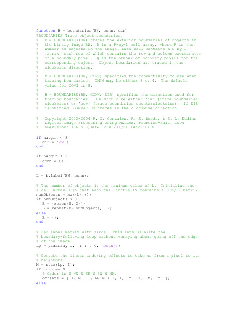
function B = boundaries(BW, conn, dir)%BOUNDARIES Trace object boundaries.% B = BOUNDARIES(BW) traces the exterior boundaries of objects in% the binary image BW. B is a P-by-1 cell array, where P is the% number of objects in the image. Each cell contains a Q-by-2% matrix, each row of which contains the row and column coordinates % of a boundary pixel. Q is the number of boundary pixels for the % corresponding object. Object boundaries are traced in the% clockwise direction.%% B = BOUNDARIES(BW, CONN) specifies the connectivity to use when% tracing boundaries. CONN may be either 8 or 4. The default% value for CONN is 8.%% B = BOUNDARIES(BW, CONN, DIR) specifies the direction used for% tracing boundaries. DIR should be either 'cw' (trace boundaries % clockwise) or 'ccw' (trace boundaries counterclockwise). If DIR % is omitted BOUNDARIES traces in the clockwise direction.% Copyright 2002-2004 R. C. Gonzalez, R. E. Woods, & S. L. Eddins% Digital Image Processing Using MATLAB, Prentice-Hall, 2004% $Revision: 1.6 $ $Date: 2003/11/21 14:22:07 $if nargin < 3dir = 'cw';endif nargin < 2conn = 8;endL = bwlabel(BW, conn);% The number of objects is the maximum value of L. Initialize the% cell array B so that each cell initially contains a 0-by-2 matrix. numObjects = max(L(:));if numObjects > 0B = {zeros(0, 2)};B = repmat(B, numObjects, 1);elseB = {};end% Pad label matrix with zeros. This lets us write the% boundary-following loop without worrying about going off the edge % of the image.Lp = padarray(L, [1 1], 0, 'both');% Compute the linear indexing offsets to take us from a pixel to its % neighbors.M = size(Lp, 1);if conn == 8% Order is N NE E SE S SW W NW.offsets = [-1, M - 1, M, M + 1, 1, -M + 1, -M, -M-1];else% Order is N E S W.offsets = [-1, M, 1, -M];end% next_search_direction_lut is a lookup table. Given the direction% from pixel k to pixel k+1, what is the direction to start with when % examining the neighborhood of pixel k+1?if conn == 8next_search_direction_lut = [8 8 2 2 4 4 6 6];elsenext_search_direction_lut = [4 1 2 3];end% next_direction_lut is a lookup table. Given that we just looked at % neighbor in a given direction, which neighbor do we look at next? if conn == 8next_direction_lut = [2 3 4 5 6 7 8 1];elsenext_direction_lut = [2 3 4 1];end% Values used for marking the starting and boundary pixels.START = -1;BOUNDARY = -2;% Initialize scratch space in which to record the boundary pixels as % well as follow the boundary.scratch = zeros(100, 1);% Find candidate starting locations for boundaries.[rr, cc] = find((Lp(2:end-1, :) > 0) & (Lp(1:end-2, :) == 0));rr = rr + 1;for k = 1:length(rr)r = rr(k);c = cc(k);if (Lp(r,c) > 0) & (Lp(r - 1, c) == 0) & isempty(B{Lp(r, c)}) % We've found the start of the next boundary. Compute its% linear offset, record which boundary it is, mark it, and% initialize the counter for the number of boundary pixels.idx = (c-1)*size(Lp, 1) + r;which = Lp(idx);scratch(1) = idx;Lp(idx) = START;numPixels = 1;currentPixel = idx;initial_departure_direction = [];done = 0;next_search_direction = 2;while ~done% Find the next boundary pixel.direction = next_search_direction;found_next_pixel = 0;for k = 1:length(offsets)neighbor = currentPixel + offsets(direction);if Lp(neighbor) ~= 0% Found the next boundary pixel.if (Lp(currentPixel) == START) & ...isempty(initial_departure_direction)% We are making the initial departure from% the starting pixel.initial_departure_direction = direction;elseif (Lp(currentPixel) == START) & ...(initial_departure_direction == direction)% We are about to retrace our path.% That means we're done.done = 1;found_next_pixel = 1;break;end% Take the next step along the boundary.next_search_direction = ...next_search_direction_lut(direction);found_next_pixel = 1;numPixels = numPixels + 1;if numPixels > size(scratch, 1)% Double the scratch space.scratch(2*size(scratch, 1)) = 0;endscratch(numPixels) = neighbor;if Lp(neighbor) ~= STARTLp(neighbor) = BOUNDARY;endcurrentPixel = neighbor;break;enddirection = next_direction_lut(direction);endif ~found_next_pixel% If there is no next neighbor, the object must just% have a single pixel.numPixels = 2;scratch(2) = scratch(1);done = 1;endend% Convert linear indices to row-column coordinates and save % in the output cell array.[row, col] = ind2sub(size(Lp), scratch(1:numPixels));B{which} = [row - 1, col - 1];endendif strcmp(dir, 'ccw')for k = 1:length(B)B{k} = B{k}(end:-1:1, :);endend。
贝叶斯高斯算法bayesgauss冈萨雷斯图像处理源代码

function d = bayesgauss(X, CA, MA, P)%BAYESGAUSS Bayes classifier for Gaussian patterns.% D = BAYESGAUSS(X, CA, MA, P) computes the Bayes decision% functions of the n-dimensional patterns in the rows of X.% CA is an array of size n-by-n-by-W containing W covariance% matrices of size n-by-n, where W is the number of classes.% MA is an array of size n-by-W, whose columns are the corres-% ponding mean vectors. A cov. matrix and a mean vector must be% specified for each class, even if some are equal. X is of size % K-by-n, where K is the number of patterns to be classified. P is % a 1-by-W array, containing the probabilities of occurrence of% each class. If P is not included in the argument, the classes% are assumed to be equally likely.%% D, is a column vector of length K. Its ith element is the class% number assigned to the ith vector in X during classification.% Copyright 2002-2004 R. C. Gonzalez, R. E. Woods, & S. L. Eddins% Digital Image Processing Using MATLAB, Prentice-Hall, 2004% $Revision: 1.11 $ $Date: 2005/01/25 14:49:45 $d = [ ]; % Initialize d.error(nargchk(3, 4, nargin)) % Verify correct no. of inputs.n = size(CA, 1); % Dimension of patterns.% Protect against the possibility that the class number is% included as an (n+1)th element of the vectors.X = double(X(:, 1:n));W = size(CA, 3); % Number of pattern classes.K = size(X, 1); % Number of patterns to classify.if nargin == 3P(1:W) = 1/W; % Classes assumed equally likely.elseif sum(P) ~= 1error('Elements of P must sum to 1.');endend% Compute the determinants.for J = 1:WDM(J) = det(CA(:, :, J));end% Evaluate the decision functions. Note the use of% function mahalanobis discussed in Section 12.2.MA = MA'; % Organize the mean vectors as rows.for J = 1:WC = CA(:,:,J);M = MA(J,:);k1 = log(P(J));k2 = 0.5*log(DM(J));L(1:K,1) = k1;DET(1:K,1) = k2;if P(J) == 0;D(1:K, J) = -inf;elseD(:, J) = L - DET - 0.5*mahalanobis(X, C, M);endend% Find the coordinates of the maximum value in each row. These maxima % maxima give the class of each pattern:[i, j] = find(D==repmat(max(D')',1,size(D,2)));% Re-use X. It now contains the max value along each column.X = [i j];% Eliminate multiple classifications of the same patterns. Since% the class assignment when two or more decision functions give% the same value is arbitrary, we need to keep only one.X = sortrows(X);[b, m] = unique(X(:,1));X = X(m, :);% X is now sorted, with the 2nd column giving the class of the% pattern no. in the 1st col.; i.e., X(j, 1) refers to the jth% input pattern, and X(j, 2) is its the class number.% Output the result of classification. d is a col. vector with% length equal to the total no. of inout patterns. The elements of% d are the classes into which the patterns were classified.d = X(:,2);。
数字图像处理实验6 冈萨雷斯
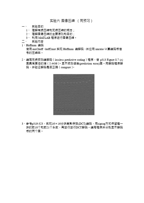
实验六图像压缩(同预习)一、实验目的1、理解有损压缩和无损压缩的概念;2、理解图像压缩的主要原则和目的;3、利用MATLAB 程序进行图像压缩。
二、实验内容1、Huffman 编码使用mat2huff,huff2mat 实现Huffman 编解码,并应用imratio 计算编码后信号的压缩率。
2、编写无损预测编解码(lossless predictive coding)程序,使p313 Figure 8.7 (c)图具有更低的熵(5.4436)。
显示预测误差(prediction error)图。
用解码程序解码,并验证解码是否正确(compare)。
3、参考p319-323,实现16×16分块离散余弦(DCT)编码,用zigzag方式保留每一块的前10个和前21个系数,再进行进行DCT解码。
编写程序并分别显示解码后的两个图。
实验程序:实验1:i=imread('Fig0804(a)(Tracy).tif'); i1=mat2huff(i);cr1=imratio(i,i1);%cr1,压缩率i2=huff2mat(i1);rmse1=compare(i,i2);figure,imshow(i);figure,imshow(i2);实验2:子程序1:function y = mat2lpc2(x, f)%本程序改自课本上那个程序,可实现更高压缩率!error(nargchk(1, 2, nargin)); % Check input argumentsif nargin < 2 % Set default filter if omittedf = 1;endx = double(x); % Ensure double for computations [m, n] = size(x); % Get dimensions of input matrixp = zeros(m, n); % Init linear prediction to 0xs = x; zc = zeros(1,n); % Prepare for input shift and pad for j = 1:length(f) % For each filter coefficient ...xs = [zc; xs(1:end - 1,:)]; % Shift and zero pad xga改加一行 p = p + f(j) * xs; % Form partial prediction sumsendy = x - round(p); % Compute the prediction error子程序2:function x = lpc2mat2(y, f)% 本程序改自课本上那个程序,可以解压error(nargchk(1, 2, nargin)); % Check input argumentsif nargin < 2 % Set default filter if omittedf = 1;endy=y';f = f(end:-1:1); % Reverse the filter coefficients[m, n] = size(y); % Get dimensions of output matrix order = length(f); % Get order of linear predictorf = repmat(f, m, 1); % Duplicate filter for vectorizingx = zeros(m, n + order); % Pad for 1st 'order' column decodes% Decode the output one column at a time. Compute a prediction based % on the 'order' previous elements and add it to the prediction% error. The result is appended to the output matrix being built.for j = 1:njj = j + order;x(:, jj) = y(:, j) + round(sum(f(:, order:-1:1) .* ...x(:, (jj - 1):-1:(jj - order)), 2));endx = x(:, order + 1:end); % Remove left paddingx=x';总程序:f=imread('Fig0807(c)(Aligned).tif');e=mat2lpc2(f);figure,imshow(mat2gray(e));h=entropy(e);c=lpc2mat2(e);figure,imshow(c,[]);rmse=compare(f,c);实验三:i=imread('Fig0804(a)(Tracy).tif');i=im2double(i);mask1=[1 1 1 1 0 0 0 0 0 0 0 0 0 0 0 01 1 1 0 0 0 0 0 0 0 0 0 0 0 0 01 1 0 0 0 0 0 0 0 0 0 0 0 0 0 01 0 0 0 0 0 0 0 0 0 0 0 0 0 0 00 0 0 0 0 0 0 0 0 0 0 0 0 0 0 00 0 0 0 0 0 0 0 0 0 0 0 0 0 0 00 0 0 0 0 0 0 0 0 0 0 0 0 0 0 00 0 0 0 0 0 0 0 0 0 0 0 0 0 0 00 0 0 0 0 0 0 0 0 0 0 0 0 0 0 00 0 0 0 0 0 0 0 0 0 0 0 0 0 0 00 0 0 0 0 0 0 0 0 0 0 0 0 0 0 00 0 0 0 0 0 0 0 0 0 0 0 0 0 0 00 0 0 0 0 0 0 0 0 0 0 0 0 0 0 00 0 0 0 0 0 0 0 0 0 0 0 0 0 0 00 0 0 0 0 0 0 0 0 0 0 0 0 0 0 00 0 0 0 0 0 0 0 0 0 0 0 0 0 0 0 ];mask2=[1 1 1 1 1 1 0 0 0 0 0 0 0 0 0 01 1 1 1 1 0 0 0 0 0 0 0 0 0 0 01 1 1 1 0 0 0 0 0 0 0 0 0 0 0 01 1 1 0 0 0 0 0 0 0 0 0 0 0 0 01 1 0 0 0 0 0 0 0 0 0 0 0 0 0 01 0 0 0 0 0 0 0 0 0 0 0 0 0 0 00 0 0 0 0 0 0 0 0 0 0 0 0 0 0 00 0 0 0 0 0 0 0 0 0 0 0 0 0 0 00 0 0 0 0 0 0 0 0 0 0 0 0 0 0 00 0 0 0 0 0 0 0 0 0 0 0 0 0 0 00 0 0 0 0 0 0 0 0 0 0 0 0 0 0 00 0 0 0 0 0 0 0 0 0 0 0 0 0 0 00 0 0 0 0 0 0 0 0 0 0 0 0 0 0 00 0 0 0 0 0 0 0 0 0 0 0 0 0 0 00 0 0 0 0 0 0 0 0 0 0 0 0 0 0 00 0 0 0 0 0 0 0 0 0 0 0 0 0 0 0 ];T=dctmtx(16);B=blkproc(i,[16 16],'P1*x*P2',T,T'); i1=blkproc(B,[16 16],'P1.*x',mask1); i2=blkproc(B,[16 16],'P1.*x',mask2); ii1=blkproc(i1,[16 16],'P1*x*P2',T',T); ii2=blkproc(i2,[16 16],'P1*x*P2',T',T); figure,imshow(ii1);figure,imshow(ii2);。
数字图像处理第三版习题解答(冈萨雷斯版)
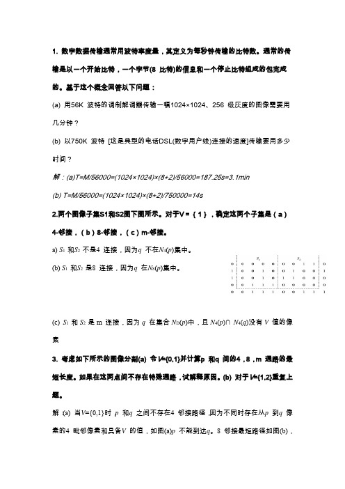
【链码: 110003301232 微分码 303003011113 形状数 003011113303 阶 12】 19 为什么伪彩色处理可以达到增强的效果呢? 由于人眼对彩色的分辨能力远远大于对黑白灰度的分辨率。 对于一般的观察者来说。 通常 能分辨十几级灰度,就是经专业训练的人员也只能分辨几十级灰度。而对于彩色来说,人的 眼睛可分辨出上千种彩色的色调和强度。因此,在一幅黑白图像中检测不到的信息,经伪彩 色增强后可较容易的被检测出来。
或解: (1) 在 V={0,1}时,p 和 q 之间通路的 D4 距离为∞,D8 距离为 4,Dm 距离为 5。 (2) 在 V={1,2}时,p 和 q 之间通路的 D4 距离为 6,D8 距离为 4,Dm 距离为 6。
4 为什么一般情况下对离散图像的直方图均衡化并不能产生完全平坦的直方 图?【因为同一个灰度值的各个象素没有理由变换到不同灰度级,所以数字图像 的直方图均衡化的结果一般不能得到完全均匀分布的直方图, 只是近似均匀的直 方图。 】 5 设已用直方图均衡化技术对一幅数字图像进行了增强, 如再用这一方法对所得 结果增强会不会改变其结果?【从原理上分析,直方图均衡化所用的变换函数为 原始直方图的累积直方图, 均衡化后得到的增强图像的累积直方图除有些项合并 外,其余项与原始图像的累积直方图相同。如果再次均衡化,所用的变换函数即 为均衡化后得到的增强图像的累积直方图(并且不会有新的合并项) ,所以不会
(c) S1 和 S2 是 m 连接,因为 q 在集合 ND(p)中,且 N4(p)∩ N4(q)没有 V 值的像 素 3. 考虑如下所示的图像分割(a) 令V={0,1}并计算p 和q 间的4,8,m 通路的最 短长度。如果在这两点间不存在特殊通路,试解释原因。(b) 对于V={1,2}重复上 题。 解: (a) 当V={0,1}时, p 和q 之间不存在4 邻接路径, 因为不同时存在从p 到q 像 素的4 毗邻像素和具备V 的值,如图(a)p 不能到达q。8 邻接最短路径如图(b),
bound2im(b, M, N, x0, y0)冈萨雷斯图像处理的源代码

function B = bound2im(b, M, N, x0, y0)%BOUND2IM Converts a boundary to an image.% B = BOUND2IM(b) converts b, an np-by-2 or 2-by-np array% representing the integer coordinates of a boundary, into a binary % image with 1s in the locations defined by the coordinates in b% and 0s elsewhere.%% B = BOUND2IM(b, M, N) places the boundary approximately centered % in an M-by-N image. If any part of the boundary is outside the% M-by-N rectangle, an error is issued.%% B = BOUND2IM(b, M, N, X0, Y0) places the boundary in an image of % size M-by-N, with the topmost boundary point located at X0 and% the leftmost point located at Y0. If the shifted boundary is% outside the M-by-N rectangle, an error is issued. XO and X0 must % be positive integers.% Copyright 2002-2004 R. C. Gonzalez, R. E. Woods, & S. L. Eddins% Digital Image Processing Using MATLAB, Prentice-Hall, 2004% $Revision: 1.6 $ $Date: 2003/06/14 16:21:28 $[np, nc] = size(b);if np < ncb = b'; % To convert to size np-by-2.[np, nc] = size(b);end% Make sure the coordinates are integers.x = round(b(:, 1));y = round(b(:, 2));% Set up the default size parameters.x = x - min(x) + 1;y = y - min(y) + 1;B = false(max(x), max(y));C = max(x) - min(x) + 1;D = max(y) - min(y) + 1;if nargin == 1% Use the preceding default values.elseif nargin == 3if C > M | D > Nerror('The boundary is outside the M-by-N region.') end% The image size will be M-by-N. Set up the parameters for this.B = false(M, N);% Distribute extra rows approx. even between top and bottom.NR = round((M - C)/2);NC = round((N - D)/2); % The same for columns.x = x + NR; % Offset the boundary to new position.y = y + NC;elseif nargin == 5if x0 < 0 | y0 < 0error('x0 and y0 must be positive integers.')endx = x + round(x0) - 1;y = y + round(y0) - 1;C = C + x0 - 1;D = D + y0 - 1;if C > M | D > Nerror('The shifted boundary is outside the M-by-N region.') endB = false(M, N);elseerror('Incorrect number of inputs.')endB(sub2ind(size(B), x, y)) = true;。
hough冈萨雷斯图像处理源代码

function [h, theta, rho] = hough(f, dtheta, drho)%HOUGHHough transform.% [H, THETA, RHO] = HOUGH(F, DTHETA, DRHO) computes the Hough% transform of the image F. DTHETA specifies the spacing (in% degrees) of the Hough transform bins along the theta axis. DRHO % specifies the spacing of the Hough transform bins along the rho % axis. H is the Hough transform matrix. It is NRHO-by-NTHETA, % where NRHO = 2*ceil(norm(size(F))/DRHO) - 1, and NTHETA =% 2*ceil(90/DTHETA). Note that if90/DTHETA is not an integer, the % actual angle spacing will be 90 / ceil(90/DTHETA).%% THETA is an NTHETA-element vector containing the angle (in% degrees) corresponding to each column of H. RHO is an% NRHO-element vector containing the value of rho corresponding to % each row of H.%% [H, THETA, RHO] = HOUGH(F) computes the Hough transform using % DTHETA = 1 and DRHO = 1.% Copyright 2002-2004 R. C. Gonzalez, R. E. Woods, & S. L. Eddins % Digital Image Processing Using MATLAB, Prentice-Hall, 2004% $Revision: 1.4 $ $Date: 2003/10/26 22:33:44 $ifnargin< 3drho = 1;endifnargin< 2dtheta = 1;endf = double(f);[M,N] = size(f);theta = linspace(-90, 0, ceil(90/dtheta) + 1);theta = [theta -fliplr(theta(2:end - 1))];ntheta = length(theta);D = sqrt((M - 1)^2 + (N - 1)^2);q = ceil(D/drho);nrho = 2*q - 1;rho = linspace(-q*drho, q*drho, nrho);[x, y, val] = find(f);x = x - 1; y = y - 1;% Initialize output.h = zeros(nrho, length(theta));% To avoid excessive memory usage, process 1000 nonzero pixel% values at a time.fork = 1:ceil(length(val)/1000)first = (k - 1)*1000 + 1;last = min(first+999, length(x));x_matrix = repmat(x(first:last), 1, ntheta);y_matrix = repmat(y(first:last), 1, ntheta);val_matrix = repmat(val(first:last), 1, ntheta);theta_matrix = repmat(theta, size(x_matrix, 1), 1)*pi/180;rho_matrix = x_matrix.*cos(theta_matrix) + ...y_matrix.*sin(theta_matrix);slope = (nrho - 1)/(rho(end) - rho(1));rho_bin_index = round(slope*(rho_matrix - rho(1)) + 1);theta_bin_index = repmat(1:ntheta, size(x_matrix, 1), 1);% Take advantage of the fact that the SPARSE function, which% constructs a sparse matrix, accumulates values when input% indices are repeated. That�s the behavior we want forthe% Hough transform. We want the output to be a full (nonsparse) % matrix, however, so we call function FULL on the output of% SPARSE.h = h + full(sparse(rho_bin_index(:), theta_bin_index(:), ...val_matrix(:), nrho, ntheta));end。
colorgrad(f--T)冈萨雷斯图像处理源代码

function [VG, A, PPG]= colorgrad(f, T)%COLORGRAD Computes the vector gradient of an RGB image.% [VG, VA, PPG] = COLORGRAD(F, T) computes the vector gradient, VG, % and corresponding angle array, VA, (in radians) of RGB image% F. It also computes PPG, the per-plane composite gradient% obtained by summing the 2-D gradients of the individual color% planes. Input T is a threshold in the range [0, 1]. If it is% included in the argument list, the values of VG and PPG are% thresholded by letting VG(x,y) = 0 for values <= T and VG(x,y) = % VG(x,y) otherwise. Similar comments apply to PPG. If T is not% included in the argument list then T is set to 0. Both output% gradients are scaled to the range [0, 1].% Copyright 2002-2004 R. C. Gonzalez, R. E. Woods, & S. L. Eddins% Digital Image Processing Using MATLAB, Prentice-Hall, 2004% $Revision: 1.6 $ $Date: 2003/11/21 14:27:21 $if (ndims(f) ~= 3) | (size(f, 3) ~= 3)error('Input image must be RGB.');end% Compute the x and y derivatives of the three component images% using Sobel operators.sh = fspecial('sobel');sv = sh';Rx = imfilter(double(f(:, :, 1)), sh, 'replicate');Ry = imfilter(double(f(:, :, 1)), sv, 'replicate');Gx = imfilter(double(f(:, :, 2)), sh, 'replicate');Gy = imfilter(double(f(:, :, 2)), sv, 'replicate');Bx = imfilter(double(f(:, :, 3)), sh, 'replicate');By = imfilter(double(f(:, :, 3)), sv, 'replicate');% Compute the parameters of the vector gradient.gxx = Rx.^2 + Gx.^2 + Bx.^2;gyy = Ry.^2 + Gy.^2 + By.^2;gxy = Rx.*Ry + Gx.*Gy + Bx.*By;A = 0.5*(atan(2*gxy./(gxx - gyy + eps)));G1 = 0.5*((gxx + gyy) + (gxx - gyy).*cos(2*A) + 2*gxy.*sin(2*A));% Now repeat for angle + pi/2. Then select the maximum at each point.A = A + pi/2;G2 = 0.5*((gxx + gyy) + (gxx - gyy).*cos(2*A) + 2*gxy.*sin(2*A));G1 = G1.^0.5;G2 = G2.^0.5;% Form VG by picking the maximum at each (x,y) and then scale% to the range [0, 1].VG = mat2gray(max(G1, G2));% Compute the per-plane gradients.RG = sqrt(Rx.^2 + Ry.^2);GG = sqrt(Gx.^2 + Gy.^2);BG = sqrt(Bx.^2 + By.^2);% Form the composite by adding the individual results and % scale to [0, 1].PPG = mat2gray(RG + GG + BG);% Threshold the result.if nargin == 2VG = (VG > T).*VG;PPG = (PPG > T).*PPG;end。
matlab基于区域轮廓的代码

基于区域的活动轮廓算法matlab代码2011-06-11 21:25% Region Based Active Contour Segmentation%% seg = region_seg(I,init_mask,max_its,alpha,display)%% Inputs: I 2D image% init_mask Initialization (1 = foreground, 0 = bg)% max_its Number of iterations to run segmentation for% alpha (optional) Weight of smoothing term% higer = smoother. default = 0.2% display (optional) displays intermediate outputs% default = true%% Outputs: seg Final segmentation mask (1=fg, 0=bg)%% Description: This code implements the paper: "Active Contours Without % Edges" By Chan Vese. This is a nice way to segment images whose% foregrounds and backgrounds are statistically different and homogeneous. %% Example:% img = imread('tire.tif');% m = zeros(size(img));% m(33:33+117,44:44+128) = 1;% seg = region_seg(img,m,500);%% Coded by: Shawn Lankton ()%------------------------------------------------------------------------function seg = region_seg(I,init_mask,max_its,alpha,display)%-- default value for parameter alpha is .1if(~exist('alpha','var'))alpha = .2;end%-- default behavior is to display intermediate outputsif(~exist('display','var'))display = true;end%-- ensures image is 2D double matrixI = im2graydouble(I);%-- Create a signed distance map (SDF) from maskphi = mask2phi(init_mask);%--main loopfor its = 1:max_its % Note: no automatic convergence testidx = find(phi <= 1.2 & phi >= -1.2); %get the curve's narrow band%-- find interior and exterior meanupts = find(phi<=0); % interior pointsvpts = find(phi>0); % exterior pointsu = sum(I(upts))/(length(upts)+eps); % interior meanv = sum(I(vpts))/(length(vpts)+eps); % exterior meanF = (I(idx)-u).^2-(I(idx)-v).^2; % force from image information curvature = get_curvature(phi,idx); % force from curvature penaltydphidt = F./max(abs(F)) + alpha*curvature; % gradient descent to minimize energy%-- maintain the CFL conditiondt = .45/(max(dphidt)+eps);%-- evolve the curvephi(idx) = phi(idx) + dt.*dphidt;%-- Keep SDF smoothphi = sussman(phi, .5);%-- intermediate outputif((display>0)&&(mod(its,20) == 0))showCurveAndPhi(I,phi,its);endend%-- final outputif(display)showCurveAndPhi(I,phi,its);end%-- make mask from SDFseg = phi<=0; %-- Get mask from levelset%---------------------------------------------------------------------%---------------------------------------------------------------------%-- AUXILIARY FUNCTIONS ----------------------------------------------%---------------------------------------------------------------------%---------------------------------------------------------------------%-- Displays the image with curve superimposedfunction showCurveAndPhi(I, phi, i)imshow(I,'initialmagnification',200,'displayrange',[0 255]); hold on; contour(phi, [0 0], 'g','LineWidth',4);contour(phi, [0 0], 'k','LineWidth',2);hold off; title([num2str(i) ' Iterations']); drawnow;%-- converts a mask to a SDFfunction phi = mask2phi(init_a)phi=bwdist(init_a)-bwdist(1-init_a)+im2double(init_a)-.5;%-- compute curvature along SDFfunction curvature = get_curvature(phi,idx)[dimy, dimx] = size(phi);[y x] = ind2sub([dimy,dimx],idx); % get subscripts%-- get suba=rand(1)*9scripts of neighborsym1 = y-1; xm1 = x-1; yp1 = y+1; xp1 = x+1;%-- bounds checkingym1(ym1<1) = 1; xm1(xm1<1) = 1;yp1(yp1>dimy)=dimy; xp1(xp1>dimx) = dimx;%-- get indexes for 8 neighborsidup = sub2ind(size(phi),yp1,x);iddn = sub2ind(size(phi),ym1,x);idlt = sub2ind(size(phi),y,xm1);idrt = sub2ind(size(phi),y,xp1);idul = sub2ind(size(phi),yp1,xm1);idur = sub2ind(size(phi),yp1,xp1);iddl = sub2ind(size(phi),ym1,xm1);iddr = sub2ind(size(phi),ym1,xp1);%-- get central derivatives of SDF at x,yphi_x = -phi(idlt)+phi(idrt);phi_y = -phi(iddn)+phi(idup);phi_xx = phi(idlt)-2*phi(idx)+phi(idrt);phi_yy = phi(iddn)-2*phi(idx)+phi(idup);phi_xy = -0.25*phi(iddl)-0.25*phi(idur)...+0.25*phi(iddr)+0.25*phi(idul);phi_x2 = phi_x.^2;phi_y2 = phi_y.^2;%-- compute curvature (Kappa)curvature = ((phi_x2.*phi_yy + phi_y2.*phi_xx -2*phi_x.*phi_y.*phi_xy)./...(phi_x2 + phi_y2 +eps).^(3/2)).*(phi_x2 + phi_y2).^(1/2);%-- Converts image to one channel (grayscale) double function img = im2graydouble(img)[dimy, dimx, c] = size(img);if(isfloat(img)) % image is a doubleif(c==3)img = rgb2gray(uint8(img));endelse % image is a intif(c==3)img = rgb2gray(img);endimg = double(img);end%-- level set re-initialization by the sussman method function D = sussman(D, dt)% forward/backward differencesa = D - shiftR(D); % backwardb = shiftL(D) - D; % forwardc = D - shiftD(D); % backwardd = shiftU(D) - D; % forwarda_p = a; a_n = a; % a+ and a-b_p = b; b_n = b;c_p = c; c_n = c;d_p = d; d_n = d;a_p(a < 0) = 0;a_n(a > 0) = 0;b_p(b < 0) = 0;b_n(b > 0) = 0;c_p(c < 0) = 0;c_n(c > 0) = 0;d_p(d < 0) = 0;d_n(d > 0) = 0;dD = zeros(size(D));D_neg_ind = find(D < 0);D_pos_ind = find(D > 0);dD(D_pos_ind) = sqrt(max(a_p(D_pos_ind).^2, b_n(D_pos_ind).^2) ... + max(c_p(D_pos_ind).^2, d_n(D_pos_ind).^2)) - 1;dD(D_neg_ind) = sqrt(max(a_n(D_neg_ind).^2, b_p(D_neg_ind).^2) ... + max(c_n(D_neg_ind).^2, d_p(D_neg_ind).^2)) - 1;D = D - dt .* sussman_sign(D) .* dD;%-- whole matrix derivativesfunction shift = shiftD(M)shift = shiftR(M')';function shift = shiftL(M)shift = [ M(:,2:size(M,2)) M(:,size(M,2)) ];function shift = shiftR(M)shift = [ M(:,1) M(:,1:size(M,2)-1) ];function shift = shiftU(M)shift = shiftL(M')';function S = sussman_sign(D)S = D ./ sqrt(D.^2 + 1);。
冈萨雷斯图像处理Matlab版本函数汇总
冈萨雷斯图像处理Matlab函数汇总(注:所有函数的头字母都应是小写)图像显示colorbar 显示彩条getimage 由坐标轴得到图像数据ice(DIPUM)交互彩色编辑image 创建和显示图像对象imagesc 缩放数据并显示为图像immovie 由多帧图像制作电影imshow 显示图像imview 在Image Viewer中显示图像montage 将多个图像帧显示为矩阵蒙太奇movie 播放录制的电影帧rgbcube 显示一个彩色RGB立方体subimage 在单个图形中显示多幅图像truesize 调整图像的显示尺寸warp 将图像显示为纹理映射的表面图像文件输入/输出Dicominfo 从一条DICOM消息中读取元数据Dicomread 读一幅DICOM图像Dicomwrite 写一幅DICOM图像Dicom-dict.txt 包含DICOM数据字典的文本文件Dicomuid 产生DICOM唯一的识别器Imfinfo 返回关于图像的文件的信息Imread 读图像文件Imwrite 写图像文件图像算术Imabsdiff 计算两幅图像的绝对差Imadd 两幅图像相加或把常数加到图像上Imcomplement 图像求补Imdivide 两幅图像相除,或用常数除图像Imlincomb 计算图像的线性组合Immultiply 两幅图像相乘或用常数乘图像Imsubtract 两幅图像相减,或从图像中减去常数几何变换Checkerboard 创建棋盘格图像Findbounds 求几何变换的输出范围Fliptform 颠倒TFORM结构的输入/输出Imcrop 修剪图像Imresize 调整图像大小Imrotate 旋转图像Imtransform 对图像应用几何变换Intline 整数坐标线绘制算法Makersampler 创建重取样器结构Maketform 创建几何变换结构(TFORM)Pixeldup(DIPUM)在两个方向上复制图像的像素Tformarray 对N-D数组应用几何变换Tformfwd 应用正向几何变换Tforminv 应用反向几何变换Vstformfwd(DIPUM)可视化正向几何变换图像匹配Cpstruct2pairs 将CPSTRUCT转换为有效的控制点对Cp2tform 由控制点对推断几何变换Cpcorr 使用互相关校准控制点位置Cpselect 控制点选择工具Normxcorr2 归一化二维互相关像素值及统计Corr2 计算二维相关系数Covmatrix(DIPUM)计算向量族的协方差矩阵Imcontour 创建图像数据的轮廓线Imhist 显示图像数据的直方图Impixel 确定像素的彩色点Improfile 计算沿着线段的像素值横截面Mean2 计算矩阵元素的均值Pixval 显示关于像素的信息Regionprops 测量图像区域的属性Statmoments(DIPUM)计算一幅图像直方图的统计中心距Std2 计算矩阵元素的标准偏差图像分析(包括分割、描述和识别)Bayesgauss(DIPUM)高斯模式的贝叶斯分类器Bound2eight(DIPUM)将4连接边界转换为8连接边界Bound2four(DIPUM)将8连接边界转换为4连接边界Bwboundaries 追踪区域边界Bwtraceboundary 追踪单个边界Bound2im(DIPUM)将边界转换为图像Boundaries(DIPUM)追踪区域边界Bsubsamp(DIPUM)对边界二次取样Colorgrad(DIPUM)计算一幅RGB图像的向量梯度Colorseq(DIPUM)分割一幅彩色图像Connectpoly(DIPUM)连接多边形的顶点Diameter(DIPUM)测量图像区域的直径Edge(DIPUM)在一幅亮度图像中寻找边缘Fchcode(DIPUM)计算边界的freeman链码Frdescp(DIPUM)计算傅里叶描绘子Graythresh 使用Ostu方法计算图像的全局阈值Hough(DIPUM)Hough变换Houghlines(DIPUM)基于Hough变换提取线段Houghpeaks(DIPUM)在Hough变换中检测峰值Houghpixels(DIPUM)计算属于Hough变换bin的图像像素Ifrdescp(DIPUM)计算逆傅里叶描绘子Imstack2vectors(DIPUM)从图像堆栈提取向量Invmoments(DIPUM)计算图像不变距Mahalanobis(DIPUM)计算Mahalanobis距离Minperpoly(DIPUM)计算最小周长多边形Polyangles(DIPUM)计算多边形内角Princomp(DIPUM)得到主分量向量和相关量Qtdecomp 执行四叉树分解Qtgetblk 得到四叉树分解中的块值Qtsetblk 在四叉树中设置块值Randvertex(DIPUM)随机置换多边形顶点Regiongrow(DIPUM)由区域生长来执行分割Signature(DIPUM)计算边界的标记Specxture(DIPUM)计算图像的谱纹理Splitmerge(DIPUM)使用分离-合并算法分割图像Statxture(DIPUM)计算图像中纹理的统计度量Strsimilarity(DIPUM)两个串间的相似性度量X2majoraxis(DIPUM)以区域的主轴排列坐标x图像压缩Compare(DIPUM)计算和显示两个矩阵间的误差Entropy(DIPUM)计算矩阵的熵的一阶估计Huff2mat(DIPUM)解码霍夫曼编码矩阵Huffman(DIPUM)为符号源建立一个变长霍夫曼码Im2jpeg(DIPUM)使用JPEG近似压缩一幅图像Im2jpeg2k(DIPUM)使用JPEG2000近似压缩一幅图像Imratio(DIPUM)计算两幅图像或变量中的比特率Jpeg2im(DIPUM)解码IM2JPEG压缩的图像Jpeg2k2im(DIPUM)解码IM2JPEG2K压缩的图像Lpc2mat(DIPUM)解压缩一维有损预测编码矩阵Mat2huff(DIPUM)霍夫曼编码矩阵Mat2lpc(DIPUM)使用一维有损预测编码矩阵Quantize(DIPUM)量化UINT8类矩阵的元素图像增强Adapthisteq 自适应直方图量化Decorrstretch 对多通道图像应用去相关拉伸Gscale(DIPUM)按比例调整输入图像的亮度Histeq 使用直方图均衡化来增强对比度Intrans(DIPUM)执行亮度变换Imadjust 调整图像亮度值或彩色映射Stretchlim 寻找对比度拉伸图像的限制图像噪声Imnoise 给一幅图像添加噪声Imnoise2(DIPUM)使用指定的PDF生成一个随机数数组Imnoise3(DIPUM)生成周期噪声线性和非线性空间滤波Adpmedian(DIPUM)执行自适应中值滤波Convmtx2 计算二维卷积矩阵Dftcorr(DIPUM)执行频率域相关Dftfilt(DIPUM)执行频率域滤波Fspecial 创建预定义滤波器Medfilt2 执行二维中值滤波Imfilter 滤波二维和N维图像Ordfilter2 执行二维顺序统计滤波Spfilt(DIPUM)执行线性和非线性空间滤波Wiener2 执行二维去噪滤波线性二维滤波器设计Freqspace 确定二维频率响应间隔Freqz2 计算二维频率响应Fsamp2 使用频率取样设计二维FIR滤波器Ftrans2 使用频率变换设计二维FIR滤波器Fwind1 使用一维窗法设计二维滤波器Fwind2 使用二维窗法设计二维滤波器Hpfilter(DIPUM)计算频率域高通滤波器Lpfilter(DIPUM)计算频率域低通滤波器图像去模糊(复原)Deconvblind 使用盲去卷积去模糊图像Deconvlucy 使用Lucy-Richardson方法去模糊Deconvreg 使用规则化滤波器去模糊Deconvwnr 使用维纳滤波器去模糊Edgetaper 使用点扩散函数锐化边缘Otf2psf 光传递函数到点扩散函数Pst2otf 点扩散函数到光传递函数图像变换Dct2 二维离散余弦变换Dctmtx 离散余弦变换矩阵Fan2para 将扇形束投影变换为并行射束Fanbeam 计算扇形射束变换Fft2 二维快速傅里叶变换Fftn N维快速傅里叶变换Fftshift 颠倒FFT输出的象限Idct2 二维逆离散余弦变换Ifanbeam 计算扇形射束逆变换Ifft2 二维快速傅里叶逆变换Ifftn N维快速傅里叶逆变换Iradon 计算逆Radon变换Para2fan 将并行射束投影变换为扇形射束Phantom 生成头部仿真模型的图像Radon 计算Radon变换小波Wave2gray(DIPUM)显示小波分解系数Waveback(DIPUM)执行多灰度级二维快速小波逆变换Wavecopy(DIPUM)存取小波分解结构的系数Wavecut(DIPUM)在小波分解结构中置零系数Wavefast(DIPUM)执行多灰度级二维快速小波变换Wavefilter(DIPUM)构造小波分解和重构滤波器Wavepaste(DIPUM)在小波分解结构中放置系数Wavework(DIPUM)编辑小波分解结构Wavezero(DIPUM)将小波细节系数设置为零领域和块处理Bestblk 为块处理选择块大小Blkproc 为图像实现不同的块处理Col2im 将矩阵列重排为块Colfilt 按列邻域操作Im2col 将图像块重排为列Nlfilter 执行一般的滑动邻域操作形态学操作(亮度和二值图像)Conndef 默认连通性Imbothat 执行底帽滤波Imclearborder 抑制与图像边框相连的亮结构Imclose 关闭图像Imdilate 膨胀图像Imerode 腐蚀图像Imextendedmax 最大扩展变换Imextendedmin 最小扩展变换Imfill 填充图像区域和孔洞Imhmax H最大变换Imhmin H最小变换Imimposemin 强制最小Imopen 打开图像Imreconstruct 形态学重构Imregionalmax 局部最大区域Imregionalmin 局部最小区域Imtophat 执行顶帽滤波Watershed 分水岭变换形态学操作(二值图像)Applylut 使用查表法执行邻域操作Bwarea 计算二值图像中的对象面积Bwareaopen 打开二值区域(删除小对象)Bwdist 计算二值图像的距离变换Bweuler 计算二值图像的欧拉数Bwhitmiss 二值击不中操作Bwlabel 在二维图像中标记连接分量Bwlabeln 在N维二值图像中标记连接分量Bwmorph 对二值图像执行形态学操作Bwpack 打包二值图像Bwperim 确定二值图像中的对象的周长Bwselect 选择二值图像中的对象Bwulterode 最终腐蚀Bwunpack 解包二值图像Endpoints(DIPUM)计算二值图像的端点Makelut 构建applylut使用的查找表结构元素(STREL)的创建和操作Getheight 得到strel的高度Getneighbors 得到strel邻域的偏移位置和高度Getnhood 得到strel邻域Getsequence 得到分解的strel序列Isflat 对平坦的strel返回值Reflect 以其中心反射strelStrel 创建形态学结构元素Translate 变换strel基于区域的处理Histroi(DIPUM)计算图像中的ROI的直方图Poly2mask 将ROI多边形转换为掩膜Roicolor 基于颜色选择ROIRoifill 在任意区域内平稳地内插Roifilt2 对ROI进行滤波Roipoly 选择多边形ROI彩色映射处理Brighten 加亮或加暗彩色映射Cmpermute 在彩色映射中重排颜色Cmunique 寻找唯一的彩色映射颜色和相应的图像Colormap 设置或得到彩色查找表Imapprox 以很少的颜色近似被索引的图像Rgbplot 绘制RGB彩色映射分量彩色空间转换Applyform 应用独立于设备的彩色空间变换Hsv2rgb 将HSV值转换为RGB彩色空间Iccread 读ICC彩色配置文件Lab2double 将L*a*b*彩色值转换为double类Lab2uint16 将L*a*b*彩色值转换为uint16类Lab2uint8 将L*a*b*彩色值转换为uint8类Makecform 创建独立于设备的彩色空间变换结构Ntsc2rgb 将NTSC值转换为RGB彩色空间Rgb2hsv 将RGB值转换为HSV彩色空间Rgb2ntsc 将RGB值转换为NTSC彩色空间Rgb2ycbcr 将RGB值转换为YCBCR彩色空间Ycbcr2rgb 将YCBCR值转换为RGB彩色空间Rgb2hsi(DIPUM)将RGB值转换为HSI彩色空间Hsi2rgb(DIPUM)将HSI值转换为RGB彩色空间Whitepoint 返回标准照明的XYZ值Xyz2double 将XYZ彩色值转换为double类Xyz2uint16 将XYZ彩色值转换为uint16类数组操作Circshift 循环地移位数组Dftuv(DIPUM)计算网格数组Padarray 填充数组Paddedsize(DIPUM)计算用于FFT的最小填充尺寸图像类型和类型转换Changeclass 改变一幅图像的类Dither 使用抖动转换图像Gray2ind 将亮度图像转换为索引图像Grayslice 通过阈值处理从亮度图像创建索引图像Im2bw 通过阈值处理将图像转换为二值图像Im2double 将图像数组转换为双精度Im2java 将图像转换为Java图像Im2java2d 将图像转换为Java缓存的图像对象Im2uint8 将图像数组转换为8比特无符号整数Im2uint16 将图像数组转换为16比特无符号整数Ind2gray 将索引图像转换为亮度图像Ind2rgb 将索引图像转换为RGB图像Label2rgb 将标记矩阵转换为RGB图像Mat2gray 将矩阵转换为亮度图像Rgb2gray 将RGB图像或彩色映射转换为灰度图像Rgb2ind 将RGB图像转换为索引图像其他函数Conwaylaws(DIPUM)对单个像素应用Conway的遗传定律Manualhist(DIPUM)交互地生成2模式直方图Twomodegauss(DIPUM)生成一个2模式高斯函数Uintlut 基于查找表计算新数组值工具箱参数Iptgetpref 获得图像处理工具箱参数的值Iptsetpref 设置图像处理工具箱参数的值Matlab数字数字图像处理函数汇总:1、数字数字图像的变换①fft2:fft2函数用于数字数字图像的二维傅立叶变换,如:i=imread('104_8.tif');j=fft2(i);②ifft2::ifft2函数用于数字数字图像的二维傅立叶反变换,如:i=imread('104_8.tif');j=fft2(i);k=ifft2(j);2、模拟噪声生成函数和预定义滤波器①imnoise:用于对数字数字图像生成模拟噪声,如:i=imread('104_8.tif');j=imnoise(i,'gaussian',0,0.02);%模拟高斯噪声②fspecial:用于产生预定义滤波器,如:h=fspecial('sobel');%sobel水平边缘增强滤波器h=fspecial('gaussian');%高斯低通滤波器h=fspecial('laplacian');%拉普拉斯滤波器h=fspecial('log');%高斯拉普拉斯(LoG)滤波器h=fspecial('average');%均值滤波器2、数字数字图像的增强①直方图:imhist函数用于数字数字图像的直方图显示,如:i=imread('104_8.tif');imhist(i);②直方图均化:histeq函数用于数字数字图像的直方图均化,如:i=imread('104_8.tif');j=histeq(i);③对比度调整:imadjust函数用于数字数字图像的对比度调整,如:i=imread('104_8.tif'); j=imadjust(i,[0.3,0.7],[]);④对数变换:log函数用于数字数字图像的对数变换,如:i=imread('104_8.tif');j=double(i);k=log(j);⑤基于卷积的数字数字图像滤波函数:filter2函数用于数字数字图像滤波,如:i=imread('104_8.tif'); h=[1,2,1;0,0,0;-1,-2,-1];j=filter2(h,i);⑥线性滤波:利用二维卷积conv2滤波, 如:i=imread('104_8.tif');h=[1,1,1;1,1,1;1,1,1];h=h/9;j=conv2(i,h);⑦中值滤波:medfilt2函数用于数字数字图像的中值滤波,如:i=imread('104_8.tif');j=medfilt2(i);⑧锐化(1)利用Sobel算子锐化数字数字图像, 如:i=imread('104_8.tif');h=[1,2,1;0,0,0;-1,-2,-1];%Sobel算子j=filter2(h,i);(2)利用拉氏算子锐化数字数字图像, 如:i=imread('104_8.tif');j=double(i);h=[0,1,0;1,-4,0;0,1,0];%拉氏算子k=conv2(j,h,'same');m=j-k;3、数字数字图像边缘检测①sobel算子如:i=imread('104_8.tif');j =edge(i,'sobel',thresh)②prewitt算子如:i=imread('104_8.tif');j =edge(i,'prewitt',thresh)③roberts算子如:i=imread('104_8.tif');j =edge(i,'roberts',thresh)④log算子如:i=imread('104_8.tif');j =edge(i,'log',thresh)⑤canny算子如:i=imread('104_8.tif');j =edge(i,'canny',thresh)⑥Zero-Cross算子如:i=imread('104_8.tif');j =edge(i,'zerocross',thresh)4、形态学数字数字图像处理①膨胀:是在二值化数字数字图像中“加长”或“变粗”的操作,函数imdilate执行膨胀运算,如:a=imread('104_7.tif');%输入二值数字数字图像b=[0 1 0;1 1 1;01 0];c=imdilate(a,b);②腐蚀:函数imerode执行腐蚀,如:a=imread('104_7.tif');%输入二值数字数字图像b=strel('disk',1);c=imerode(a,b);③开运算:先腐蚀后膨胀称为开运算,用imopen来实现,如:a=imread('104_8.tif');b=strel('square',2);c=imopen(a,b);④闭运算:先膨胀后腐蚀称为闭运算,用imclose来实现,如:a=imread('104_8.tif');b=strel('square',2);c=imclose(a,b);数字数字图像增强1. 直方图均衡化的Matlab 实现1.1 imhist 函数功能:计算和显示数字数字图像的色彩直方图格式:imhist(I,n)imhist(X,map)说明:imhist(I,n) 其中,n 为指定的灰度级数目,缺省值为256;imhist(X,map) 就算和显示索引色数字数字图像X 的直方图,map为调色板。
- 1、下载文档前请自行甄别文档内容的完整性,平台不提供额外的编辑、内容补充、找答案等附加服务。
- 2、"仅部分预览"的文档,不可在线预览部分如存在完整性等问题,可反馈申请退款(可完整预览的文档不适用该条件!)。
- 3、如文档侵犯您的权益,请联系客服反馈,我们会尽快为您处理(人工客服工作时间:9:00-18:30)。
function [g,NR,SI,TI] = regiongrow(f,S,T)
%REGIONGROW Perform segmentation by regin growing.
% [g,NR,SI,TI] = REGIONGROW(F,S,T).S can be an array(the same size as F) % with a 1 at the coordinates of every seed point and 0s elsewhere.S can % also be a single seed value.Similarly,T can be an array(the same size % as F) containing a threshold value for each pixel in F.T can also be a % scalar,in which case it becomes a global threshold.
%
% On the output,G is the result of region growing,with each region
% labeled by a different integer,NR is the number of regions,SI is the % final seed image used by the algorithm,and TI is the image consisting % of the pixels in F that satisfied the threshold test.
f=double(f);
%If S is a scalar,obtain the seed image.
if numel(S)==1
SI=f==S;
S1=S;
else
%S is an array.Eliminateduplicate,connected seed locations to reduce
%the number of loop executions in the following sections of code.
SI=bwmorph(3,'shrink',Inf);
J=find(SI);
S1=f(J);%array of seed value.
end
TI=false(size(f));
for K=1:length(S1)
seedvalue=S1(K);
S=abs(f-seedvalue)<=T;
TI=TI|S;
end
%Use function imreconstruct with SI as the marker image to obtain the
%regions corresponding to each seed in S.Functionbwlabel assigns a
%different integer to each connected region.
[g,NR]=bwlabel(imreconstruct(SI,TI));
end。
