POV-Ray与Diamond_3_联用作图简介第二节
英国“钻石”同步辐射光源(DIAMOND)

英国“钻石”同步辐射光源(DIAMOND)2010-08-10 | 文章来源: | 浏览次数: 659 |【大中小】璀璨夺目的“钻石”光源英国第一台第三代同步辐射光源DIAMOND坐落于英国南牛津郡(South Oxfordshire)迪德科特镇(Didcot)。
它的名字来源有两种说法:一种说法是该项目的发起人迈克普尔(Mike Poole)由DIpole And Multipole Output for the Nation at Daresbury(国家在达斯伯里的偶极和多极输出)的缩写构思了DIAMOND这个名字;另一种说法是DIAMOND表达了同步辐射光既硬(指“硬”X射线的电磁波谱区)又明亮,就像“钻石”。
不管哪种说法更准确,与法国“太阳”光源(SOLEIL)相比,英国“钻石”光源(DIAMOND)的名字毫不逊色,DIAMOND 光源就像钻石那样璀璨夺目。
DIAMOND光源的紫外线和X射线具有远非常规光源可比的品质和亮度,其亮度为医用X光机的1千亿倍,科技工作者用它将能更深入地研究物质、材料及生物样品的基本结构。
利用同步辐射技术开展的科学实验,可望在生物技术、医学、环境和材料研究中取得突破性进展。
英国南牛津郡的迪德科特镇DIAMOND光源鸟瞰2002年,英国政府批准建造DIAMOND光源,其辐射能量及光束性能首先被优化为高能的欧洲同步光源ESRF的补充。
它的主要目标是生成高亮度、高强度的可调光源,建成英国第一的研究基地,开展不同学科领域交叉学科的研究。
DIAMOND是40多年来英国投资兴建的最重要的大科学装置和最大的民用科研基地,由英国科学和技术设施委员会STFC的中心实验室研究理事会CCLRC( Council for the Central Laboratory of the Research Councils)与英国最大的生物医学研究慈善机构——威康信托基金会(Wellcome Trust)共同建设,双方各投资86%和14%。
diamond_3_教程系列
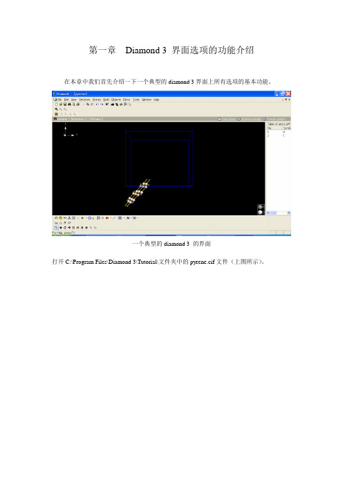
第一章Diamond 3 界面选项的功能介绍在本章中我们首先介绍一下一个典型的diamond 3界面上所有选项的基本功能。
一个典型的diamond 3 的界面打开C:\Program Files\Diamond 3\Tutorial\文件夹中的pyrene.cif文件(上图所示)。
第一节File菜单系列1.1 File菜单简介File菜单系列,包括Windows系统常规的几种选项(如图2 所示。
)图1.2 File菜单系列1.2 常用选项1.2.1Open 选项点击该选项,可以看到diamond 3 可以打开的所有文件类型(如图3所示)。
图1.3 Diamond 3 支持的阅读格式前三项是该公司开发的Diamond 及Endeavour软件的默认格式。
其中Cif文件格式最为通用。
ICSD/Crystin及CSD-FDat是两个晶体学数据库输出的文件格式。
Protein Data Bank 格式表示支持蛋白质晶体数据库文件。
常用的格式还包括笛卡儿xyz座标格式,这在构建特殊结构模型时极为便利,比如我们会在后面章节中提到的螺旋体的构建。
1.2.2 Save 选项这里默认的保存格式是Diamond 3 Document (*.diamdoc)格式。
1.2.3 Save as选项共包括三个次级选项:图1.4 Diamond 3 Save as的三个次级选项在实际应用中,前两项功能相似,我们以Save Document As为例进行介绍:Save Document As提供14种文件格式:图1.5 Diamond 3 支持的14结构储存格式前三项为该公司开发的结构文件格式,常用的为第一项*.diamdoc。
通常在我们处理一个较为复杂的结构时,一次无法完成或者以后仍需要修改时,必须保存成该格式。
该格式详细保留了您的一切设置(分子模型的模式、原子的半径颜色、键长等),demo版不提供该格式的保存。
其它格式则通常并不实用。
POV-Ray与Diamond3联用作图简介
POV-Ray与Diamond 3 联用作图简介第一节POV-Ray基本知识POV-Ray,全名是Persistence of Vision Raytracer,是一个使用光线跟踪绘制三维图像的开放源代码免费软件。
很多漂亮的图片就是由POV-ray来制作的。
本文的主要目的在于介绍如何利用Diamond软件联合POV-Ray 画图,我们不可能将所有的功能加以介绍。
本节简要介绍一下。
1.坐标系统POV-Ray是基于Ray-tracing的渲染软件,学习它的第一个事情便是认识其坐标系统。
2. POV-Ray文件的基本构成和很多计算机语言一样,文件格式中有很多属于专用语言,这些文字在程序中往往表现为彩色。
一个基本的POV-Ray文件有如下几个部分:一些头文件、摄像机定义、场景物体定义、灯光定义。
a. 头文件,常用的包括:#include "colors.inc" // 定义基本颜色#include "shapes.inc" // 定义基本形状物体#include "textures.inc" // 定义一些物体属性注://后面的文字是注释,不参与程序运行。
b. 摄像机位置和观察方向当用POV-Ray的标记语言来表示一个摄像机的时候,我们可以这样来写:camera {location <0, 2, -3> //(大家可以想象摄像机在坐标中的位置)look_at <0, -1, 2> //(摄像机的位置确定后,还要让镜头对着某个方向)up x*1 //(up和right定义了纵横视口比例)right y*1}正规写法如下:camera {location <0.0, 2.0, -3.0>look_at <0.0, -1.0, 2.0>right x*image_width/image_height}c. 主要物体比如我们要在<0, 0, 0>位置(原点)放置一个半径为2黄色的球体可以表示为(注意{}总是成对出现,color是系统默认关键字,黄色若想成为关键字,被默认为黄色,应首字母大写):sphere {<0, 0, 0>, 2texture {pigment {color Yellow} }}到此,我们完成了所有工作,就可以渲染(run)了,但您看到的将是一个黑色背景上的一个很淡的黄色的实心圆。
Diamond 做图

用同样的方法,为另一个芘环创建平面。 可以通过 Tools/Calculate/Angle Between Planes 命令来测量二者之间的 夹角和距离
例 在Diamond 中展示并观察五氧化二 磷分子晶体的结构,并为其添加多面体 结构。 五氧化二磷结构文件 P4O10.cry 是2.0 版本中的一个文件,提取出来。用3.0打 开。
选择Creat a picture automatically自动打 开文件中所保存的图形 选择Launch the picture creation assistant. 则可进行一些自己的设计。
选择创建分子。
如果选择 Creat a blank picture 则得到 一空白图形。可以使用不同方式得到五 氧化二磷分子晶体的结构。 点击场景 顶部的 按钮,可得 到文件中所保存的原始结构图形。
对原子显示形式和场景颜色进行设置。 在创建原子类型时可设置范围为 “2*2*2cell”类型。 为突出石英晶体的规则外形,可以以Si为 中心原子创建多面体结构
晶体结构的展示与美化
原子名称
原子价态 空间群
键长
晶体模型的展示形式 在晶体背景的任意空白处单击鼠标右键, 选Model 一栏。若点击 Model and Radi.., 弹出对话框也可以改变原子显示形式。 或Picture菜单 Model and Radi.. 或下方工具栏
在Diamond软件的欢迎界面,选择“Creat a new document 或选择工具栏中的 FileNew命令。 在弹出对话框中有三种选择形式:创建一 个空白文档、输入结构参数创建文档和从 已有文件中采用相关数据创建文件。我们 选择第二种类型。
ArtCAM Pro 2012 POV-Ray 渲染教程说明书
You can make your own scenes by adding in a large flat mesh and setting up the material to become a reflective plate. To save the scene, export it as a .3DA.
Adding in a reflective base Scene:
A reflective plate can be added into the Assembly to further enhance the final rendering by adding better reflection and colour
Image window setup:
Re-size ArtCAM Screen to make 3D view smaller and sized to match size for image
Can resize entire ArtCAM session screen or only 3D view. Image is captured on size of 3D view. The larger the 3D view is, the better quality the image but the file size is larger and will take longer to render.
The POV-Ray function can be accessed from the Window pull down menu in ArtCAM Pro and JewelSmith. It becomes available when working with Project and Assembly pieces. When your Project is complete with all components in the Assembly, you can create the rendered image.
晶体结构立体模型建构软件-Diamond的使用指南
晶体结构立体模型建构软件-Diamond的使用吴平伟中国海洋大学材料科学与工程研究院E-mail: wupingwei@晶体结构立体模型建构软件-Diamond的使用在使用Diamond软件构造晶体模型时,需要知道晶体的结构数据,即晶体的空间群、晶胞参数和原子坐标。
晶体结构数据可以手动输入,也可以直接从晶体信息文件中获得。
我们将通过几个例子来说明软件的使用方法。
一、NaCl晶体结构模型的构造下面我们以NaCl为例手动输入晶体结构数据。
NaCl晶体的结构数据为:空间群Fm-3m(225);晶胞参数a=5.64Å;原子坐标Na:4a, Cl:4b。
我们将通过这个例子学会如下操作:1、学会手动输入晶体结构数据;2、学会晶体模型的构造;3、学会旋转晶体模型,从不同的角度观察;4、学会改变背景和原子及晶胞的颜色等参数;5、学会以一种原子为中心,另一种原子为配位原子构造配位多面体;6、学会多面体外观的设计。
打开软件,界面如下图所示:点击“File| New”,出现一对话窗口,如下图,选择第二个选项,按“OK”。
结果生成一个名字为Diamond1的空白的页面,同时弹出一个名字为New Structure的对话窗口,点“下一步”,在新弹出的窗口中确认Crystal Structure with cell and Spacegroup被选中,在Cell length中输入5.64,如下图:注意Space group(空间群)后是否我们需要的NaCl晶体的空间群Fm-3m(225),如果不是,点击Browse钮,在弹出的对话窗口中选中Fm-3m(225),即在Fm-3m(225)上点击使其变蓝色,如下图。
点“OK”回到前面的对话窗口。
点“下一步”(在出现的如下图的对话框中可以输入原子坐标,即在“Atomic parameters“中输入相应的元素符号和原子坐标值,但我们将在其他的地方做这个工作)点“下一步”,在出现的Completing the new structure Assistant窗口中有三个选项:Start structure picture; Launch the structure picture creation assistant;Create structure picture automaticly。
diamond-3-教程系列1.01
GB50057—1994 建筑物防雷设计规范(2000年版)
GB50343—2004 建筑物电子信息系统防雷设计规范
GB 50303—2002 建筑电气工程施工质量验收规范
GB 50074—2002 石油库设计规范
GB 50156—2002(2006 年版)汽车加油加气站设计与施工规范
GB50169-2006电气装置安装工程接地装置安装及验收规范
13.8
将不同的电气装置、导电物体等,用接地导体或浪涌保护器以某种方式连接起来,以减小雷电流在它们之间产生的电位差。
13.9
建筑物需要规定和控制雷击电磁脉冲环境的区域,可划分为LPZ0A、LPZ0B、LPZ1……LPZn+1区。
13.10
也称电涌保护器,用于限制暂态过电压和分流浪涌电流的装置,它至少应包含一个非线性电压限制元件。
一、检查并记录电涌保护器数量、型号、安装位置及工艺,各级电涌保护器的主要技术参数应符合设计规范要求,电涌保护器装置应有具备检测资格的部门出具的检测报告或主管机构颁发的《防雷产品使用许可证》。
二、电涌保护器的标志应完整和清晰,表面应平整、光洁、无划伤、无裂痕和烧灼痕或变形。有劣化显示及工作状态指示的电涌保护器其状态指示应与生产厂家产品说明相一致。没有劣化显示及工作状态指示的电涌保护器,应检查电涌保护器表面手感温度,当接近或大于人体温度时,应更换电涌保护器。
Diamond装机小技巧:Diamond与POV-RAY关联的问题

Diamond 装机小技巧:Diamond 与POV-RAY 关联的问题作者:Monster编辑:CCL 适读人群:正在学习晶体可视化软件的小菜鸟,被Diamond 装机以及与POV-RAY 关联问题困扰的朋友。
最近小编在学习晶体可视化相关知识。
工欲善其事必先利其器,小编选择了较为流行的Diamond 软件。
但在装软件的过程中却遇到了一些问题,最棘手的是如何实现Diamond 与POV-RAY 的关联。
现将这些经验分享出来,希望能够帮到遇到同样问题的朋友们。
1. Diamond 软件安装:本文所用的是Diamond 3 版本,电脑系统为win 10,32 位。
目前,Diamond 已经更新到4.41,官方正式版软件是收费的(可以去度娘找找破J版)。
对于Diamond 3,无需安装得到系统C 盘,直接安装在非系统盘,比如D 盘;新建文件夹,然后按照引导按照即可。
安装完成后在Diamond3/Tutorial 文件夹下打开任意一个实例文件(本教程打开的是C60.cif ,如下图所示)。
届时,Diamond 3 安装完成。
2. 安装POV-RAY:Diamond 安装完成后,软件中已经嵌入好POV-RAY 选项。
依次点击:'Tools' - 'POV-RAY' - 'Render into Bitmap...' ,会弹出如下图所示对话框。
因为你还没有装POV-RAY, 所以Diamond 无法调用POV-RAY 。
POV-RAY 是免费的,直接前往POV-RAY 官网下载即可。
POV-RAY 最新版式POV-RAY 3.7 。
但是POV-RAY3.7之后,Diamond 无法直接调用。
小编我尝试了多种方法都无法实现连用(如果你知道如何解决,或者知道什么原因,欢迎在评论区留言,以方便大家。
)。
无论是安装在Diamond 同一个文件夹下,还是按照在系统C 盘,都无法解决这个问题。
Diamond 软件应用于原子堆积模式教学的研究

经过亿万年的演化,地球上的现存物质主要以高度规则的晶体状态存在。
迄今,科学家们对晶体材料进行了广泛的、长期的、深入细致的研究[1]。
因此,在无机化学类课程和材料类课程的教学中,晶体材料的学习占用了很大的篇幅。
按照由易到难的知识特点,各种教材在介绍晶体材料时,都是从原子的紧密堆积出发,将单质原子假想为等径的刚性球体,通过借用空间几何的方法研究原子的堆积模式,继而将原子的密堆积研究成果应用于复杂的不等径球体构成的多元分子的微观结构研究中[2,3]。
这种教学内容次序的安排符合学生的认知习惯,有利于知识的掌握。
但是,教材作为纸媒体,对于完整展现原子堆积立体模式非常困难,即使在教学中引入了多媒体方式,也不能够充分体现原子堆积模式的演变过程。
学生在学习该部分知识时,普遍存在一定的难度,有些学生甚至因为不能掌握原子堆积的基础知识,出现了厌学现象,导致了多米诺骨牌效应,影响了后续的《无机化学》《结构化学》《材料科学基础》《晶体化学》等基础课程的学习。
因此,如何找到一种简单易行并且能准确阐述原子堆积模式演变过程收稿日期:2020-03-02基金名称:安徽省质量工程项目(批准号:2016jyxm0952、2017jxtd034);淮南师范学院质量工程重点项目(批准号:2019hsjy20)作者简介:文桂林,男,湖北随州人,淮南师范学院副教授,博士。
研究方向:功能MOFs 材料的研究与开发。
Diamond 软件应用于原子堆积模式教学的研究文桂林,胡云虎,潘路,刘道富,魏亦军,朱其永,陈永红(淮南师范学院化学与材料工程学院,安徽淮南232038)摘要:原子堆积模式是学习晶体结构知识的基础,教学过程中存在结构图难以描画、堆积过程无法动态展现的缺点,学生很难掌握。
在此以面心立方堆积结构的教学为例,通过Diamond 专业软件从刚性原子球、原子阵列、原子层到空间立体堆积的全过程进行演示,将教学对象动态化和直观化,从而实现专业知识借助专业软件进行可视化教学的目的,降低了理论知识的学习难度,符合学生的认知习惯,最终可提升专业理论课的教学质量,为科研-教学的有机结合提供了事实依据。
POV-Ray与Diamond_3_联用作图简介第二节
POV-Ray与Diamond 3 联用作图简介(第二节)15151晶体论坛荣誉出品窦伟兰州大学化学化工学院第二节Diamond中的POV-Ray设置其实很多晶体类软件比如ORTEP-3,Mercury 2.2 等均可输出pov 文件。
但是ORTEP-3功能过于简单,Mercury的POV设置没有完善。
目前,相容性较好的应该属Diamond 3了。
按照我们前面的介绍,若想实现软件间的兼容必须先解决晶体结构中的原子和键的表达问题。
Diamond 3软件使用的是Sphere(代表atom)和Cyclinder(代表bond)的组合方式,具体说来有以下几点:(1)将所有的原子(包括衍生出的)和化学键分别成组,联动操作要分别设置原子组和键组;(2)默认c轴方向为初始方向,在您进行任意旋转时,程序只需对比并记住您的旋转方向即可,采取rotate 命令很容易实现;原子坐标的变化引起的大量数据的变动得以巧妙解决;(3)文件编写简洁清晰,易于后期修改(这是我们本文一切的起点)。
1.基本设置进入POV-Ray设置界面非常容易,下辖的五个选项中常用的是Global Settings、Render Into Bitmap和Create Scene File,其他两个选项实际上用处不大。
2.Global Setting里Settings这里的选项和设置是整个作图程序的关键步骤,主要从四个方面设置图片效果。
2.1 Materials:提供原子或键的材质选择,可供选择的材质非常多,但常用的是前五项。
为了便于对效果进行对比,我们选择800*600分辨率,全充满模型进行作图,其他条件不变(限于篇幅,只演示了Default 模式的设置过程;不对图片进行后期处理,因而采用Render Into Bitmap 方式,得到.bmp格式的图片):后面的各项材质选择均采用如上步骤,得到的效果如下图:材质类型 材质效果(未设置光源)特点及说明Default朴实无华Dull虚幻缥缈常用于配合光源构建美图Plastic华丽夺目不用光源,同样构建超强效果Rubber温文儒雅Shiny细致精巧最具匠心的设计,在全充满模型里最常用。
中望3D实例教程-Diamond

自定义这个角度的视图,命名为View。
插图66
第152步:
在装配页面插入女戒,放置在原点。
插图67
第153步:
移动坐标系在原点上,沿着X轴旋转-45°。
插图68
第154步:
对女戒沿着Y轴移动0.2mm
插图69
移动完毕后女戒底部接近曲面位置
插图610
第155步:
在装配页面插入男戒,放置在原点。
插图360
第86步:
选择实体,在右键菜单里进入面属性,赋予颜色位白色,透明度为80%。
插图361
第87步:
在属性下拉菜单下,进入零件。
插图362
切换到运行参数页面
插图363
单击*号后到模型树分别选取参数D,参数和初始值会出现在运行参数里,应用并确认。
插图364
第88步:
开启工具页面下的零件制表命令,会弹出下图询问,单击否。
插图45
第95步:
切换过滤器,使得在装配环境下可以同时捕捉到零件和组件对象。
插图46
第96步:
在直线的端点上创建工作平面
插图47
第97步:
逐个插入钻石零件到男戒装配下,插入钻石类型为坐标,插入后固定组件。
插图48
第98步:
完成两侧1.3钻石的装配
插图49
第99步:
完成两侧1.4钻石的装配
插图410
第100步:
插图56
第111步:
在上步工作平面上绘制草图
插图57
第112步:
使用驱动曲线放样,创建曲面。
插图58
第113步:
使用双轨放样,不缝合实体。
插图59
第114步:
删除上步多余的面
晶体模型绘制Diamond3.2

晶体结构立体模型建构软件(Diamond)教程中国海洋大学材料科学与工程研究院晶体结构立体模型建构软件-Diamond的使用在使用Diamond软件构造晶体模型时,需要知道晶体的结构数据,即晶体的空间群、晶胞参数和原子坐标。
晶体结构数据可以手动输入,也可以直接从晶体信息文件中获得。
我们将通过几个例子来说明软件的使用方法。
一、NaCl晶体结构模型的构造下面我们以NaCl为例手动输入晶体结构数据。
NaCl晶体的结构数据为:空间群Fm-3m(225);晶胞参数a=5.64Å;原子坐标Na:4a, Cl:4b。
我们将通过这个例子学会如下操作:1、学会手动输入晶体结构数据;2、学会晶体模型的构造;3、学会旋转晶体模型,从不同的角度观察;4、学会改变背景和原子及晶胞的颜色等参数;5、学会以一种原子为中心,另一种原子为配位原子构造配位多面体;6、学会多面体外观的设计。
打开软件,界面如下图所示:图1点击“File| New”,出现一对话窗口,如下图,选择第二个选项,按“OK”。
图 2结果生成一个名字为Diamond1的空白的页面,同时弹出一个名字为New Structure的对话窗口,点“下一步”,在新弹出的窗口中确认Crystal Structure with cell and Spacegroup被选中,在Cell length中输入5.64,如下图:图 3注意Space group(空间群)后是否我们需要的NaCl晶体的空间群Fm-3m(225),如果不是,点击Browse 按钮,在弹出的对话窗口中选中Fm-3m(225),即在Fm-3m(225)上点击使其变蓝色,如下图。
点“OK”回到前面的对话窗口。
中心对称图4点“下一步”(在出现的如下图的对话框中可以输入原子坐标,即在“Atomic parameters“中输入相应的元素符号和原子坐标值,但我们将在其他的地方做这个工作)图5点“下一步”,在出现的Completing the new structure Assistant窗口中有三个选项:Start structure picture; Launch the structure picture creation assistant; Create structure picture automaticly。
Diamond

3.2 Diamond 软件基础知识
各类工作场景介绍
阅读Diamond3.0软件的操作手册(格式为.PDF)
找到Diamond3.0软件的安装路径,打开 Diamond3.0软件中名为Tutorial的文件夹, 里面存有五个. CIF文件
导入Diamond3.0软件中的 Sample\Minerals文件夹里作为范例的39个 已绘制好的晶体结构
平行投影法(正、斜投影)
Parallel Projection
1. 为原子设置特殊材质
2. (1)选择Model and Radii命令,确定晶体的表现模式 3. (2)选择picture/Atom design命令 ,对选中的某一类原子
进行设置 :Material按钮 ; POV-Ray选项(选第二个选项Use pre-
注: •不能以原有格式保存 •Window/start 回到开始场景
改变背景颜色:Picture/Layout…/Background
【实例3-2】在Diamond3.0 软件中创建SiO2的晶体结构。
•为突出石英晶体的规则外型,可以
创建多面体结构
选择晶胞范围
以Si为中心原子
晶体信息栏
ICSD
Picture工具栏的使用
每个空间群的记号可用Schonflies记号或国际 记号或两种结合使用。
Diamond构建晶体模型的基本步骤:
•确定构建哪个晶体的模型 •收集资料(查找该晶体的晶胞参数和晶体中原子的坐 标参数) •在Diamond软件中建模(在各对话框中输入相关数据) •在Diamond软件的操作场景中对晶体模型进行修改、 美化、标注和观察 •现场教学或将晶体模型的三维文件导出(图片或网页 格式)
abc
Diamond晶体结构绘制软件教程
DIAMOND 教程 B:高级示例
20
分子结构 . . . . . . . . . . . . . . . . . . . . . . . . . . . . . . . . . . . . . . . . . . . . . . . . . . . . . . . . . . . . . . . 20
安装 POV-RayTM . . . . . . . . . . . . . . . . . . . . . . . . . . . . . . . . . . . . . . . . . . . . . . . . . . . . . . 57
恢复工厂设置 . . . . . . . . . . . . . . . . . . . . . . . . . . . . . . . . . . . . . . . . . . . . . . . . . . . . . . . . . . . 58
Diamond 2 用户必读 . . . . . . . . . . . . . . . . . . . . . . . . . . . . . . . . . . . . . . . . . . . . . . . . . . . . . . 59
Windows 软件基本操作指南 . . . . . . . . . . . . . . . . . . . . . . . . . . . . . . . . . . . . . . . . . . . . . . . 63
绘制图像 . . . . . . . . . . . . . . . . . . . . . . . . . . . . . . . . . . . . . . . . . . . . . . . . . . . . . . . . . . . . . . . . 7
如何用Diamond构建Polyhedral图

关于如何构建晶体结构,我们前期介绍了CrystalMaker这款软件。
下面几期内容我们将介绍另外一款常用的晶体结构软件“ Diamond ”。
本期内容将介绍如何用Diamond构建立体多边形结构(本期内容来自广州大学汤政斌同学的投稿,在此表示感谢)。
1. 导入晶胞:①把cif文件拖入diamond即可;或者open a file(直接打开)②打开后,弹出以下窗口,点击下一步,即可。
③继续点击下一步。
④当弹出picture design设置窗口时,建议把background颜色选白色(个人爱好)。
⑤按下一步,再按完成,即出现下图。
2. 添加与修饰多面体①点击工具栏的Build,选择Polyhedra——Add Polyhedra(添加多面体)。
②选择中心原子与对应配位原子,构成多面体。
(首先Al和O配位) 然后,点击Design。
③ a. 弹出polyhedra design 设置窗口(颜色选了turquoise,透明度调至0.6),然后点击Material。
b. 弹出Material settings 窗口如下图(Blue 调至0.3)个人觉得此处可以把多面体调亮一点,更有光泽。
c. 总体设置如下图。
d. 设置完上述步骤,即可点击Apply now。
e. Al 和O 配位的效果图如下。
④重复步骤二的① - ③,建立Lu和O的配位的多面体结构(红色、透明度:0.8;material setting——Red:0.50)。
即可得到如下效果图。
⑤添加骨架,点击工具栏的picture——Polyhedral Designs——把勾去掉添加骨架后的效果图⑥设置Al和Lu原子的颜色:工具栏——picture——atom design效果图3. ①选择其中一个Lu原子点击鼠标右键——copy②点击工具栏的Edit——Copy To New PictureCopy to new picture 后的效果图如下:③选中整个多面体结构,点击工具栏Build——Connect Atoms效果图④选中整个多面体,对着骨架右键,点击Add——Bond Labels弹出设置窗口如下图效果图如下⑤ a.为中心原子添加标签,右键中心原子,Add——Atoms Labelsb. 点击工具栏Picture ——Atoms Designs(设置中心原子颜色)效果图⑥ a.选择随便其中一个原子,右键——copy;再点击工具栏Edit——copy to new picture,得到新的图如下,把所有氧原子选中(按着Ctrl键,点击鼠标左键),再点击右键——destroy ——atoms.b. 对球体进行颜色编辑4. 导出图片。
Diamond作图

删减法:将对 描述结构无关 的原子或基团 隐藏,只显示 一部分
9
二 含有巨型离散水簇的笼状配合物
举例
主体
[Co(H2O)6⊂Co8L12]6+
[HL = 4,6-di(2-pyridyl)-1,3,5-triazine-2-ol]
客体
多核水簇(H2O)21
其他
咪唑,KBr/KCl,EtOH
Man-Li Cao, J-J Wu, H-J Mo,etc,. J. AM. CHEM. SOC. 2009, 131, 3458–3459
Diamond作图
目录
一 Diamond简述 二 描述复杂结构中原子的配位环境 三 描述三维孔状配位聚合物 四 描述具有螺旋结构的配位聚合物
2
引
Diamond的出现
MOFs 的广泛应用
吸附分离
气体存储
光学材料
MOFs
磁性材料
催化
其他
3
引
Diamond的出现
MOFs 的研究过程
MOFs
晶体透明 晶型较好
Man-Li Cao, J-J Wu, H-J Mo,etc,. J. AM. CHEM1.2SOC. 2009, 131, 3458–3459
二
结构分析
[Co(H2O)6⊂Co8L12]6+ (H2O)21
配合物的3D氢键框 架
不规 则阴 离子
{Br6(H2O)14}6{Cl6(H2O)16}6-
10
二
结构分析
[Co(H2O)6⊂Co8L12]6+的结构
Co的配位
Co的多面体
Man-Li Cao, J-J Wu, H-J Mo,etc,. J. AM. CHEM. SOC. 2009, 131, 3458–3459
diamond做图

Diamond3.1在空穴内作出小球的步骤:*使用软件:dingwei网友破解的diamond3.1版,可到晶体之星论坛上去找*使用的cif的参考文献:J. Am. Chem. Soc.2006, 128, 1304.1.用diamond打开cif文件,相信这个大家都会。
2.整理结构,增减原子直到作出一个完整的框架,我只做了文献Fig1中的一个框架,做两个只是花点时间重复操作而已。
图形如下:3.作出Zn原子的多面体:点击diamond最上方的按钮“Build-Polyhedra-Add Polyhedra”出现如上面板,将Central atom groups 指定为Zn,Ligand atom groups指定为O,然后确定,就得到Zn的多面体图。
默认的多面体是白色的,可以自行调整颜色。
用鼠标选中所有原子,右击鼠标点“Edit-Polyhedron Designs…”在Fill Color处改颜色;在other里修改Ligand原子半径,改为1。
改完后得到下图:4.下面作出哑原子:选中任意两个处于体对角线的对称原子,或者全部原子(选全部原子要求结构框架是完整的,不然哑原子不落在空穴的中心),之后点击“Structure-Insert Atom…”,确定后在空穴的中心出现一个哑原子。
5.编辑哑原子:选中哑原子,右击鼠标“Edit-Atom Designs…”,先改颜色,再改半径。
将半径改成9(或者你自己喜欢的其他大小),点“apply now”,会出现警告提示,不管它,点确定。
然后点“Close”就好了!然后调整角度,直到你自己满意为止。
6.保存图片:目前的分辨率是很低的,首先要调整一下分辨率:点“Picture -Layout…”选用Bitmap ,设定Resolution 为600,这样就可以提高分辨率了。
在Backgroud 里可以改背景色。
最后Save as -Save Graphic as -选TIF 的格式,保存就得到一张图片。
Diamond 3.1手册
User ManualDIAMONDUser ManualVersion3.2User ManualIntel,Pentium and Pentium II are(registered)trademarks of Intel Corp.,Santa Clara,CA,USA.AMD and Athlon are registered trademarks of AMD Corp.,Sunnyvale,CA,USA.Windows,Windows NT and PowerPoint are registered trademarks of the Microsoft Corp.,Redmond,WA, USA.”POV-Ray T M”,”Persistence of Vision”,”POV-Team T M”and”POV-Help”are trademarks of the POV-Team T M, Williamstown,Australia.The POV-Ray T M package which is present on the Diamond CD-ROM as a free bonus;customers of Diamond do not pay for POV-Ray in any way.You can download the official POV-Ray package without charge from .The distribution present on the Diamond CD-ROM is the official version of POV-Ray; it is permitted under the terms of the General License in thefile POVLEGAL.DOC.The POV-Team does not endorse the distributor or its products.The POV-Team receives no compensation for this distribution.For detailed information about the POV-Ray license,please read the”GENERAL LICENSE AGREEMENT”(also called”POVLEGAL.DOC”).Copyright c 1997-2009by CRYSTAL IMPACTDr.K.Brandenburg&Dr.H.Putz GbRRathausgasse30D-53111BonnGermanyE-mail:info@World Wide Web:ContentsIntroduction1Tutorial A:Introductory Examples2 First Steps (2)Creating a Picture (7)Adapting the Design of the Picture (12)Reflection:The D IAMOND Concept17 Task (17)Step-by-Step (17)Connectivity and Filter (18)Exploring Unknown Crystal Structures (18)Using Crystal Structure Pictures (19)Tutorial B:Advanced Examples20 Molecular Structures (20)Exploring an Unknown Structure (25)Zeolite Framework (34)Creating High Quality Pictures Using POV-Ray T M (43)Creating Video Sequences (49)Where to get Help55 Support56Appendix57 Installation (57)Online Update (57)Install POV-Ray T M (57)Restore Factory Settings (58)What’s New for Diamond2Users (59)Basic Windows Software Handling (63)References66 Index67Introduction1 IntroductionYou have crystal structure data(either space group/unit cell/atomic parameters or afile(e.g.CIF)) and would like to...•create high-quality pictures for a presentation or publication?•understand the construction principles of the structure?•visualize the construction principles in various ways for your students?Excellent.That’s exactly what you can do with D IAMOND,a modern software package for visual-izing crystal structures at the atomic level.The new version3has been designed to make the initial steps as simple as possible1.As a result,you can create beautiful pictures of your crystal structure without ever reading this manual.Nevertheless,Diamond is a really powerful package offering a large variety of options far beyond these initial steps.In order to be able to use the full power of Diamond,we strongly recommend to read this manual,following our recommendations:1.First of all,you are certainly eager to get your new D IAMOND software package running onyour computer straight away and create some pictures for testing.Hence,please install the software as described on p.57(if you have not already done so),and work through the tutorial session A(p.2),following the instructions given in the text.2.Once you have created yourfirst pictures,we recommend to reserve a little bit of time forreflection,preferrably not during a busy day between several phone calls,meetings and fre-quently interrupting colleagues.3.Have a seat in an armchair with the manual and a nice cup of coffee or tea,and read the chapter”Reflection”on p.17.Think about yourfirst steps in tutorial A,and consider what you would like to do with the software concerning your own research.4.You might even want to have afirst look at the chapter”Tutorial B:Advanced Examples”(p.20)while sitting in your chair,in order to get an impression of what will happen next.5.Afterwards,return to your computer and perform Tutorial B.In doing so,you will learn a lotabout D IAMOND’s most prominent features.6.Finally,you should try to”play around”with the software as you like,probably trying someexamples from your own research activities.7.If you need help,please refer to the corresponding chapter on p.55in this manual in order toget an overview over the various ways D IAMOND can support you.1If you have already used the previous D IAMOND version2,you should read the chapter”What’s New for Diamond2 Users”(p.59)in the appendix.This chapter may also be interesting for new users who would like to get an overview over the highlighting new features in D IAMOND version3.2Tutorial A:Introductory ExamplesTutorial A:Introductory ExamplesFirst StepsWe will start the tutorial with a rather typical situation:The crystal structure data of a certain com-pound are present in a CIF-file2,based on which a picture of the crystal structure shall be created.In our case,the CIF-file of Fullerene(C60)has been exported from the Pauling File Binaries Edition3. If you have not already done so,please start the D IAMOND software now4.It will display the so-called”Start Screen”,using which you can perform the most common operations(like importing a crystal structurefile or opening a recently used document)by just a single mouse click(fig.1).Fig.1:The so-called”start screen”offering a variety of typicalfile operations,e.g.import or opening of recently used documents.Please click on”Open afile”in order to import the structure data;the”Open”dialog will be dis-played.Make sure that thefile type at the bottom of the dialog is set to”CIF(*.cif)”,then select the file”c60.cif”in the”Tutorial”subdirectory of the D IAMOND program directory(e.g.”C:\Program Files\Diamond3\Tutorial”).Finally,please press”Open”.2CIF(=Crystallographic Information File)is one of the most commonfile formats for storing and exchanging crystal structure data.For example,IUCr-journals like”Acta Crystallographica”offer downloads of CIF-files for published crystal structures.More information about CIF can be found at /iucr-top/cif/index.html 3Pauling File Binaries Edition,published by ASM International,Materials Park,Ohio,U.S.A.4If your colleagues have used D IAMOND on your PC before,we strongly recommend to restore the default(factory) settings as described in the appendix(p.58)before you follow the tutorial sessions in this manual.A lot of frequently used commands can also be executed by pressing the corresponding buttonin the toolbar or by pressing a certain combination of keyboard buttons.Once you know thesebuttons and key combinations by heart,your work will become more quick andfluently.If amenu command can also be executed using a toolbar button or key combination,this is indicatedby a small pictogram to its left and/or the key combination to its right.In our case,you could e.g.have selected the”Open”command from the”File”menu,pressedthe toolbar button or pressed the key combination”Ctrl+O”.(”Ctrl+O”means that you keepthe Ctrl-button on your keyboard pressed and press the”O”).If you have just installed D IAMOND(i.e.if the option settings are still equivalent to the factory settings),the”File Import Assistant”will be displayed(fig.2),using which you can control the individual steps of the import procedure(e.g.recognition offile type etc.).Fig.2:The”File Import Assistant”guides you through the options which apply to the import of crystal structure datafiles.Please click on the”Next”button at the bottom of the assistant,and check if thefile format which has been determined automatically from the contents of the selectedfile is correct.Below,the number of data sets which can be imported from thefile(1in our case)is displayed(fig.3).Fig.3:On the second page of the”File Import Assistant”you should check if thefile format which has been determined automatically is correct.If not,please select the correct format using the ”drop-down”box in the center of the dialog.Please press”Next”to advance to page3of the assistant.Here,you can select if you would like to let D IAMOND create a structure picture automatically,use the”Structure Picture Creation Assistant”or start with a blank picture.In our case,we would like to keep thisfirst tutorial as simple as possible,so please select”Create picture automatically”from the”If the dataset is a crystal structure”combobox (fig.4).Please click on the”Next”button to advance to the fourth(andfinal)page of thefile import assistantFig.4:On the third page of the”File Import Assistant”you can select if(and how)you would like to create afirst picture for the imported crystal structure data.(fig.5).If you mark the”Do not show this assistant again”checkbox(don’t do this now),the complete”file import”operation will be performed automatically next time you import a structure file.Press the”Finish”at the bottom of the assistant.D IAMOND will import the crystal structure data and display a picture which has been created automatically(fig.6).Fig.5:On thefinal page of the”File Import Assistant”you can select if the assistant shall be displayed again on your nextfile import,or if the import procedure shall be performed”in silence”(i.e.automatically).Now that both crystal structure data have been imported as well as a structure picture has been created,we will explore the D IAMOND user interface in order to learn about the various displaying options.Please have a look at the screen(orfig.6):The dominating view in the working area5is the structure picture,currently displaying the cubic arrangement of C60”balls”.To the right of the structure picture,two so-called”panes”are dis-played:On the upper right-hand side,the Tables pane by default displays a short overview of the most important crystal structure data(Data brief).In this pane,you can also display various other tables(e.g.atomic parameters,created atoms or planes,distances and angles measured by the user etc.).These tables are accessible by clicking on the phrase with the small”arrow down”to its right (currently”Data brief”)at the top of the tables pane.Please go ahead and try to display the”Table of created atoms”:Click on”Data brief”,then select ”Table of Created Atoms”from the drop-down list.Afterwards,please display the”Data brief”again by selecting it from the drop-down list,and click on the black background in the structure picture 5The working area in a D IAMOND is the space between the toolbar at the top and the status bar at the bottom.Fig.6:The crystal structure data have been imported from thefile”c60.cif”.DIAMOND has created a picture automatically;besides this,a short overview of the most important crystal structure data (”data brief”)as well as a summary of the contents of the picture are displayed.(left mouse button)to make it the active pane again.On the lower right-hand side,the so-called Properties pane displays various kinds of information about the structure picture and the currently selected objects,e.g.•Structure picture contents•Created atoms in structure picture•Selected objects•Distances between/around selected atoms•Linearity/planarity of selected atoms•etc.The Properties pane can be set to”Automatic”mode(by selecting the correspondingfirst line in the dropdown box at its top)so that it always displays information depending on the currently selected objects.This”Automatic mode”is also the default setting,so there is no need to change it now.At the top of the structure picture and the Tables pane,the so-called Navigation bar(fig.7)provides quick access to other viewing options(data sheet,distances and angles analysis,powder diffraction pattern,all structure pictures)for the current structure as well as to the”structure level”or the ”document level”,providing an overview over all pictures of the current structure or all crystal structures contained in the current D IAMOND document,respectively.D IAMOND documentfiles (*.diamdoc)can contain more than a single crystal structure as well as more than one picturefor each crystal structure!well as to the”structure level”and the”document level”.On the left-hand side of the Navigation bar,the currently active view(e.g.”Picture1”)is given in the context of the current document,separated by’>’signs which indicate the hierarchy.For example,”c60.cif>S1252286>Picture1”means that currently picture”Picture1”of the crystal structure titled”S1252286”is displayed which is contained in the D IAMOND document”c60.cif”.In addition to the structure picture(s),there are three different views available for the current struc-ture:Data sheet The Data sheet contains all information that is currently known about the structure,i.e.it is an extended version of the data brief.Distances and angles Here a table as well as a histogram representation of the distances and angles between the various atoms in the structure is displayed.Powder pattern The powder diffraction pattern is calculated from the crystal structure data.Both a list of individual reflections as well as a diffraction diagram are presented.Various parameters of the diffraction pattern calculation(radiation,wavelength,LP-correction,profile function etc.)as well as the diagram(scaling,colors etc.)can be adjusted.Please walk through these views by clicking on the corresponding symbols in the Navigation bar, and try to change the settings e.g.for the diffraction pattern or the distances and angles calculation. If you click on the structure name in the navigation bar(in our case”S1252286”),you will obtain a thumbnail overview of all pictures which have been created for the current crystal structure(”struc-ture level”),as well as the”Data brief”providing a quick overview over the most important crystal structure data.If you click on the document name in the Navigation bar(”c60.cif”in our case;the”top level”in the document hierarchy),an overview over all structures in the current document is provided(”document level”).If you click on(select)a certain structure in the table at the top,you will obtain a thumbnail overview of all pictures which have been created for this crystal structure as well as the”Data brief”providing a quick overview over the most important crystal structure data.Thefirst tutorial session isfinished at this point;you have got an overview over the user interface and some important dialog elements.We will now start working with D IAMOND in the next chapter, by manually entering the crystal structure data and creating a picture”on your own”.Creating a PictureYou will now learn how to enter crystal structure data manually which may be necessary if no structure datafile is available(e.g.if the crystal structure data are given in some printed publication): Please execute D IAMOND if it is not already running.Afterwards,you will have to create a new D IAMOND document(in the previous session,this has been done automatically during thefile import procedure):Please select the”New”command from the”File”menu(or press the correspondingtoolbar button).A completely empty document will be displayed.Now you have to enter the crystal structure data;we will use the data of quartz(SiO2)taken from the entry”S541934”of the Pauling File Binaries Edition:Please select the”New Structure...”command from the”Structure”menu;this will open the New structure assistant guiding you through the input of the required data(like space group,unit cell or atomic parameters).The assistant will display an opening screen with some hints about its purpose;please press”Next”to advance to the second page (fig.8)on which you will start entering your data.Fig.8:On this page of the New structure assistant,you can select if you would like to enter crystal structure or molecule structure data.For crystal structure data,you have to provide space group and unit cell parameters.Please make sure that”Crystal structure with cell and space group”is selected,the click on the ”Browse”button to the right of the”space group”input line.In the dialog which opens,please select the space group”P3121(152)”(fig.9)and click”OK”.The space group will be copied to the New structure assistant page.Fig.9:Using this dialog you can select the appropriate space group,supported by additional infor-mation about the currently selected space group on the right hand side.Afterwards,please enter the unit cell parameters a=4.535˚A and c=5.17˚A(all inputfields which arefixed by the space group are automatically disabled).Finally,change the”Title of the new structure”at the bottom of the page to”Quartz low”,since the data correspond to the low temperature modification of quartz.Your window should now look similar tofig.10.Fig.10:Space group,unit cell parameters and title of the structure have been entered.Please press”Next”to advance to the next page of the assistant where you have to enter the atomic parameters(elements,oxidation states and coordinates).The element of thefirst atom you would like to enter is Si;its oxidation state in this compound is+4.The oxidation state of an element mustbe given right after the element symbol,so please enter”si+4”as element symbol in the”Atom”inputfield.Afterwards,press the<Tab>button on your keyboard to advance to the inputfield”x/a”.Please enter0.4487in thisfield and press<Tab>to advance to”y/b”.Enter0,advance to”z/c”(<Tab>)and enter0.3333.Now that you have entered all data for the atom,press the”Add”button to the right(or simply<Return>)to add the data to the table below(fig.11).Fig.11:The atomic parameters for thefirst atom(Si+4(0.4487,0.0,0.3333))have been entered. Now,you have to enter the parameters for the second atom(O-2)which are”O-2(0.367,0.2952,0.2427)”. Simply follow the procedure described above for Si+4.Once you have pressed the”Add”button, please compare your window tofig.12.Afterwards,press”Next”to advance to thefinal page of the assistant.Here you can select if(and how)you would like to create a structure picture for the data you have just entered.While in the previous session the picture has been created automatically,you will now learn how this can be achieved”semi-manually”using the so-called Structure picture creation assistant(which provides the most common options for creating crystal structure pictures).We recommend to use it until you have gained some experience and can perform the individual steps using the menu or toolbar buttons. Please make sure that the boxes to the left of”Start structure picture”and”Launch the StructureFig.12:The atomic parameters for both atoms in the asymmetric unit of the quartz structure have been entered.Picture Creation Assistant”are checked,then click”Finish”.Note that the structure picture in the background is still empty;you now have to build a structuralmodel based on the crystal structure data you have just entered.This is central aspect of theD IAMOND concept which is described in more detail in the next chapter on p.17.Right after the New Structure Assistant has closed,a new(empty)picture will be created,and the Structure Picture Creation Assistant will open.Thefirst page of the assistant offers the option to destroy all objects currently present in the structure picture,which is of course only applicable if a structure picture is already existing before the Structure picture creation assistant is called.In our case,the picture is still empty,so simply press”Next”to advance to the second page of the assistant (fig.13).Fig.13:Thefirst step when building up a structural model is to select the atoms which shall be displayed.The second page of the Structure picture creation assistant offers a variety of options for this task.The Structure picture creation assistant cannot only be used to build new structure pictures butalso to modify existing ones.You can generally call this assistant by selecting the”Picture Cre-ation Assistant...”command from the”Guidance”submenu of the”Picture”menu.Thefirst thing you generally have to do when creating a structure picture is to define the atoms which shall be displayed.The second page of the Structure Picture Creation Assistant offers the most common methods to do this.You should select the method depending on your compound.In our case,we would like tofill two unit cells in each direction,so please mark”Fill cell range with atoms”,and select”2x2x2cells”from the”Range”combobox(fig.14).Afterwards,press”Next”to advance to the third page of the assistant.This page is dedicated to the completion of structural fragments to which the atoms created on theFig.14:DIAMOND willfill eight unit cells(two in each direction)with atoms.The atoms will be connected by bonds(based on the current connectivity settings),and the unit cell edges will be displayed as well.previous page belong.In our case,we would like to draw polyhedra around the Si-atoms:Please deselect”Fill coordination spheres”,and mark the checkbox”Create polyhedra around”instead. Afterwards,enter”Si”in the input line to the right of”Central atom elements”.Besides this,make sure that the”Create cell edges”as well as the”Connect atoms”checkbox at the top of the page are checked.All other options should be unchecked(fig.15).Finally,press”Next”.Fig.15:We would like DIAMOND to create polyhedra around the Si-atoms which are created by the options selected on the previous page.The method described here to create polyhedra is only one of several ways to perform this task inD IAMOND.Other possibilities are e.g.to select a center atom as well as the ligand atoms in thestructure picture and execute the”Construct polyhedron”command from the”Build/Polyhedra...”submenu afterwards,or to use the”Build/Polyhedra.../Add polyhedra”dialog in which you candefine the atom groups for center as well as ligand atoms separately.While the previous two pages of the assistant were basically dedicated to building up the structural model(sometimes also called the”creation of the primary atoms”),the fourth page provides some options to define the design of the picture.You can e.g.change the model from the default”Balls and Sticks”to”Wires”or”Spacefilling”,select the layout of the screen(e.g.screen or A4-page), and define the quality of the display(rendered etc.).An important option on this page is”Avoid duplicate atom main colors”which should generally be checked if a new picture is created.We will use the default settings on this page,so simply press”Next”to advance to the following page. Here,you can select the way you would like to look at the structural model.For example,you could choose viewing along a certain unit cell axis:Please select”[001]projection(view along c axis)”which is generally quite appropriate for monoclinic axis b settings.Please select”(No change)”fromthe”Viewing direction”combobox.Thefinal option on this page is also important;you should normally check the”Adjust enlargement factor and position tofit picture in drawing area”so that the complete structural model is displayed as large as possible automatically.Afterwards,please click on”Finish”.The structure picture will be created according to the options you selected(fig.16).Fig.16:Using the Structure picture creation assistant,you have created yourfirst structural model. Congratulations!You have justfinished creating yourfirst picture of a crystal structure on your own! However,please do not close this picture yet:The next important thing to do is to adapt the design of the picture to your requirements.This will be described in the next chapter.Adapting the Design of the PictureIn the previous chapter,you have created a structural model of quartz.Now,we will see how the design of the model can be changed to emphasize certain aspects you would like to present to your audience.We will continue working on the structure picture right at the point where we stopped in the previous chapter.Please note that from now on we will no longer include the complete contents of the DIAMOND window in structure pictures.Besides this,we will display the contents of the actual structurepicture with a white background in the manual which is more appropriate for printing and reading.Of course,the background of your structure picture on the screen will be black like in the previoustutorial sessions.Your aim concerning this structure picture is to present different aspects of the crystal structure of quartz to your audience.In this context,it would be nice to have parts of the structure being displayed in different models,each focusing on different aspects(like packing of atoms,3d-network, local atomic environments).We will start by displaying some atoms in the corner on the lower right hand side of the picture in the space-filling model(and not in the”Balls and Sticks”model which is the default representation).The first thing you have to do is to select the atoms for which the”displaying model”shall be changed. Please press the left mouse button somewhere in the lower right hand corner inside the structure picture,and move the mouse up and to the left,thus spanning a selection rectangle on the screen. When the mouse cursor is close to the center of the structure picture,release the mouse button;all atoms within this rectangle will be selected(which can be seen by a yellow/blue frame around them) (fig.17).Fig.17:The atoms in the corner on the lower right hand side have been selected,as indicated by the yellow or blue frames around them.Note the remark above concerning the background color of the structure picture!!Now that the atoms for which the displaying model shall be changed have been selected,please choose the”Model and Radii...”command from the”Picture”menu.You willfind commands to build a structural model(e.g.add atoms or bonds)in the”Build”menu,while commands which change the design of individual atoms or even the whole structurepicture are present in the”Picture”menu.If you would like to add abstract objects(like planes,atom vectors or labels),you willfind appropriate commands in the”Objects”menu.From the”Model”combobox at the top,please select”Space-filling”,then press”OK”.The atomsTutorial A:Introductory Examples13 you have selected in the structure picture will be displayed with their”space-filling”radii.The selection frames are still present around them,so please press the<Esc>button on your keyboard to release the selection and remove the frames(fig.18).Fig.18:The atoms which have been selected in the previous step are now drawn with their”space-filling”radii.Let’s summarize what we have up to now:One part of the structure picture presents the crystal struc-ture of quartz as corner-connected SiO4-tetrahedra,another part shows the spacefilling character of the atomic arrangement.A third way to look at the crystal structure of quartz is to describe it as a three-dimensional network of covalent bonded atoms.Hence,we will change the model for a part of the structure picture to”wires/sticks”to emphasize this important point of view.Please draw a selection rectangle somewhere in the center of the picture similar to the one used for the space-filling model(press the left mouse button,move the mouse until the selection rectan-gle which is displayed contains the objects you would like to select,andfinally release the mouse button).Before we can actually change the model to”wires/sticks”,we have to remove all polyhedra within the selection rectangle in order to make the actual bonds visible:Please select the”Polyhedra”com-mand from the”Destroy”submenu of the”Build”menu(in short:select”Build/Destroy/Polyhedra”in the menu).The atoms and bonds previously hidden by the polyhedra surfaces will become visible. Note that the atoms are still selected(fig.19)!Fig.19:In the center of the structure,some polyhedra have been removed in order to make the bonds visible.Now,you can change the model for the selected atoms:Please open the”Model and Radii...”dialog from the”Picture”menu,then select the model”Wires/Sticks”in the combobox at the top of the dialog.Afterwards,click”OK”(the dialog will close)and press the<Esc>button to release the。
- 1、下载文档前请自行甄别文档内容的完整性,平台不提供额外的编辑、内容补充、找答案等附加服务。
- 2、"仅部分预览"的文档,不可在线预览部分如存在完整性等问题,可反馈申请退款(可完整预览的文档不适用该条件!)。
- 3、如文档侵犯您的权益,请联系客服反馈,我们会尽快为您处理(人工客服工作时间:9:00-18:30)。
POV-Ray与Diamond 3 联用作图简介(第二节)
15151晶体论坛荣誉出品
窦伟
兰州大学化学化工学院
第二节Diamond中的POV-Ray设置
其实很多晶体类软件比如ORTEP-3,Mercury 2.2 等均可输出pov 文件。
但是ORTEP-3功能过于简单,Mercury的POV设置没有完善。
目前,相容性较好的应该属Diamond 3了。
按照我们前面的介绍,若想实现软件间的兼容必须先解决晶体结构中的原子和键的表达问题。
Diamond 3软件使用的是Sphere(代表atom)和Cyclinder(代表bond)的组合方式,具体说来有以下几点:(1)将所有的原子(包括衍生出的)和化学键分别成组,联动操作要分别设置原子组和键组;
(2)默认c轴方向为初始方向,在您进行任意旋转时,程序只需对比并记住您的旋转方向即可,采取rotate 命
令很容易实现;原子坐标的变化引起的大量数据的变
动得以巧妙解决;
(3)文件编写简洁清晰,易于后期修改(这是我们本文一切的起点)。
1.基本设置
进入POV-Ray设置界面非常容易,下辖的五个选项中常用的是Global Settings、Render Into Bitmap和Create Scene File,其他两个选项实际上用处不大。
2.Global Setting里Settings
这里的选项和设置是整个作图程序的关键步骤,主要从四个方面设置图片效果。
2.1 Materials:
提供原子或键的材质选择,可供选择的材质非常多,但常用的是前五项。
为了便于对效果进行对比,我们选择800*600分辨率,全充满模型进行作图,其他条件不变(限于篇幅,只演示了Default 模式的设置过程;不对图片进行后期处理,因而采用Render Into Bitmap 方式,得到.bmp格式的图片):
后面的各项材质选择均采用如上步骤,得到的效果如下图:
材质类型 材质效果(未设置光源)
特点及说明
Default
朴实无华
Dull
虚幻缥缈
常用于配合光源构建美图
Plastic
华丽夺目
不用光源,同样构建超强效果
Rubber
温文儒雅
Shiny
细致精巧
最具匠心的设计,在全充满模型里最常用。
2.2 Background :
背景选择是构建高质量图片的一个重要因素。
程序提供了多种选项,常用的包括单一背景(白/黑色)、渐变背景、云彩背景等。
Monochrome color:在选择颜色时需要调到第二项Color Range中挑选一种颜色,再回到Monochrome color中。
Color Range:提供渐变效果非常好用,这和Mercury里的功能非常类似,但Diamond 通常用于展现多原子复杂体系的结构,因而这一功能似乎不经常用。
Pre-defined texture:提供了几种以云彩为主的背景图片,这些图片已在POV-Ray程序中被默认,易于在图片中直接调用。
本人曾尝试用自己的图片代入,但都失败了。
最常用的一幅大概就是:Summer sky 了:
2.3Bottom:
该选项提供了多种底面效果,包括影子、镜面效果、倒影效果等等,但是该项选择很明显与您的主体的尺寸是有关系的,主体太大,
在有限的画布上可能有时体现不出Bottom效果,这时需要在POV-Ray程序中进行相应的设置。
一般常用的模式包括以下几种(分辨率:800*600;材质:Shiny;背景:Summer sky;不对图片进行后期处理,因而采用Render Into Bitmap方式,得到.bmp格式的图片):
Bottom类型Bottom效果(未设置光源)
No floor
Monochrome
Aluminum
Mirror
Ocean
2.4 Light:
光源的设置是比较难于描述的。
程序提供了四种光源模式,parallel和point light是最简单的两种,在这两种光源中,存在着基本的几个参数:光源的位置、光的颜色,就可以确定了。
而且在选择bottom时不用太注意。
另外两种光源spotlight和cyclinder light稍麻烦,我们可以有一张示意图(图1)看出,这两种光源有类似的一些设置:Bottom设置,最好是选择除No_floor之外的底板类型。
光源的位置:用<x, y, z>表示
光源的半径:Radius
光源的指向:point_at <x1, y1, z1>
光源照到物体上采用定光圈大小:falloff
这四项是必须设置的,其他的在我们的领域中并不常用。
需要注意的是, 光源指向物体时,spotlight光源的半径越大,离物体越远,物体被更大范围和程度的照亮,但如果光圈太小,也无济于事,所以一般Radius< falloff,比如本例中radius =5,falloff = 9。
Cyclinder的设置也容易分析。
通常,我们在处理复杂结构分子时,常选的光源位置为<100,100,-100>,光源指向位置point_at <0, 0, 0>。
光源半径
radius 5
光源位置(<50,50,-50>)light_source{
<50,50,-50>
color rgb<1,1,1>
spotlight
point_at<0,0,0>
radius 5
falloff 9
tightness 05
fade_power
}
图1
调整Radius和falloff大小,可以形成以下效果:
两个关键参数效果图
light_source { // #1
<50,50,-50>
color rgb <1,1,1>
spotlight
point_at <0,0,0>
radius 5
falloff 9
tightness 05
fade_distance 2
fade_power 0.2
}
light_source { // #1
<50,50,-50>
color rgb <1,1,1>
spotlight
point_at <0,0,0>
radius 9
falloff 9
tightness 05
fade_distance 2
fade_power 0.2
}
light_source { // #1
<50,50,-50>
color rgb <1,1,1>
spotlight
point_at <0,0,0>
radius 5
falloff 5
tightness 05
fade_distance 2
fade_power 0.2
}
我们还是回到Diamond 程序来看看具体的设置:由于实际上常用的光源是平行光,可以选择parallel,位置输入常用值<100, 100, -100>,颜色,一般选白色,其他的选项就可以不填写了(如果是
spotlight, 别忘了bottom设置、Radius及Falloff设置)。
点击靠右侧中部的Add,可以将我们刚才定义的光源保存起来,以后用起来就很方便。
根据需求,您可以保存常用的一些光源设置。
在操作面板的下部还有四个选项,也是很关键的选项,尤其是第一个:Assumed gamma。
该选项可以用来调节光照强度,值越小,光照越强,画面越亮(很多朋友经常问,同样的设置,自己的图总是很暗,主要是该值使用了默认值2.2,太大了)。
后面的选项,是基于三基色的成分调整,数值的改变可使主体颜色偏红、偏绿或是偏蓝。
我们首先对比,其他条件不变时,Assumed gamma由2.0变为1.0时图片画面的变化:
当Ambient light由1,1,1变为2,1,1时,画面的变化(偏红):
未完待续:第三节Diamond结果文件的POV-Ray修饰。
