MOXA-CP134U板卡安装说明0222
Moxa Universal PCI Smart Serial Board 快速安装指南说明书

P/N: 1802001142327 *1802001142327*Universal PCI Smart Serial BoardQuick Installation GuideVersion 1.2, January 2021Technical Support Contact Information/support2021 Moxa Inc. All rights reserved.OverviewMoxa’s Universal PCI (UPCI) multiport serial boards can be installed in PCI or PCI-X slots and support both 3.3V and 5V PCI/PCI-X.Package ChecklistUPCI board are shipped with the following items:• 1 Moxa UPCI multiport serial board•Low-profile bracket (low-profile models only)•Quick installation guide (printed)•Warranty cardNOTE Notify your sales representative if any of the above items are missing or damaged.Hardware Installation ProcedureThe Universal PCI board MUST be plugged into the PC before the driver is installed.Follow the steps below:1.Select serial transmission mode. This step is for certain modelslisted below. If your product on hand is not included, please directly go to step2.If your model is CP-112UL Series/CP-114UL Series/CP-118U Series/ CP-132UL Series/CP-134U Series/CP-138U Series, you will need to set onboard DIP switches for each port.(Refer to “Dip Switch Settings” section to complete the DIPswitches setting)2.Install the board. Power off the PC and then plug the board firmlyinto any open PCI or PCI-X expansion slot.3.Plug the connection cable into the board’s connector. (Refer to“Pin Assignments” section for the cable pin assignment).4.Start system and verify the driver initialization. Software Installation Information1.Get the driver at . Based on the OS type, choosethe corresponding driver.2.Installing the driver:•For Windows OS (Take the installation of Win7 as an example)2.1. Unzip and execute the .exe file2.2. Follow the instructions to install the drivers•For LinuxExecute the following commands from the Linux prompt:2.1. Get the driver at and unzip the file:#cd /#mkdir moxa#cd moxa#cp /<driverdirectory>/driv_linux_smart_<version>_build_<build_date>.tgz .#tar -zxvfdriv_linux_smart_<version>_build_<build_date>.tgz2.2. Install the driver:#cd mxser#./mxinstall2.3. Verify the driver statusUse the Moxa diagnostic utility to verify the driver status:#cd /moxa/mxser/utility/diag#./msdiag2.4. Test the tty portUse the Moxa terminal utility to test the tty ports:#cd /moxa/mxser/utility/term#./mstermDIP Switch SettingsCP-112UL Series/CP-112UL-I SeriesMode S1 S2 S3RS-232 ON – –RS-422 OFF ON –4-Wire RS-485 OFF OFF ON2-Wire RS-485 OFF OFF OFFCP-114UL Series/CP-114UL-I SeriesMode S1 S2 S3RS-232 – – ONRS-422 – ON OFF4-Wire RS-485 ON OFF OFF2-Wire RS-485 OFF OFF OFFCP-118U Series/CP-118U-I SeriesMode S1 S2 S3RS-232 – – ONRS-422 – ON OFF4-Wire RS-485 ON OFF OFF2-Wire RS-485 OFF OFF OFFCP-132UL SeriesMode S1 S2 Illustration RS-422 – OFF2-Wire RS-485 ON ON4-Wire RS-485 OFF ONCP-134U Series/CP-134U-I SeriesRS-422 or RS-485 mode: Use the jumper to cover the two columns on the left of the jumper pins.RS-232 mode: Use the jumper to cover the two columns on the right of the jumper pins. CP-138U Series/CP-138U-I SeriesMode S1 S2 RS-422– ON 4-Wire RS-485 ON OFF 2-Wire RS-485OFFOFFPin AssignmentsCP-102U SeriesMale DB9 RS-232 PinSignal 1 DCD 2 RxD 3 TxD 4 DTR 5 GND 6 DSR 7 RTS 8CTSCP-102UL SeriesFemale DB25 RS-232 Pin Signal Pin Signal 1 – 14 – 2 DCD1 15 DTR1 3 GND 16 DSR1 4 CTS1 17 RTS1 5 RxD1 18 TxD1 6 – 19 – 7 – 20 – 8 – 21 DCD0 9 DTR0 22 GND 10 DSR0 23 CTS0 11 RTS0 24RxD0 12 TxD0 25 – 13–––CP-104JU SeriesRJ45 (RS-232) Pin Signal 1 DSR 2 RTS 3 GND 4 TxD 5 RxD 6 DCD 7 CTS 8CTRCP-104ULMale DB25 (CBL-M44M25x4-50) Pin Signal 2 TxD 3 RxD 4 RTS 5 CTS 6 DSR 7 GND 8 DCD 20DTR(CBL-M44M9x4-50) (OPT4-M9A) Pin Signal 1 DCD 2 RxD 3 TxD 4 DTR 5 GND 6 DSR 7 RTS 8 CTS Male DB9RJ45 (OPT4-RJ45A)Pin Signal 1 DSR 2 RTS 3 GND 4 TxD 5 RxD 6 DCD 7 CTS 8DTR8-pin RJ45CP-112UL SeriesMale DB9 (CBL-M25M9x2-50) Pin RS-232 RS-422/RS-485-4W RS-485-2W1 DCD TxD-(A) –2 RxD TxD+(B) –3 TxD RxD+(B) Data+(B)4 DTR RxD-(A) Data-(A)5 GND GND GND6 DSR – –7 RTS – –8 CTS – – 9–– –CP-114UL SeriesMale DB9 (CBL-M44M9x4-50)PinRS-232 RS-422/RS-485-4W RS-485-2W1DCD TxD-(A) – 2 RxD TxD+(B) – 3 TxD RxD+(B) Data+(B) 4 DTR RxD-(A) Data-(A) 5 GND GND GND 6 DSR – – 7 RTS – – 8 CTS – – 9–– –Male DB25 (CBL-M44M25x4-50)Pin RS-232RS-422/RS-485-4WRS-485-2W2 TxD RxD+(B) Data+(B)3 RxD TxD+(B) –4 RTS – –5 CTS – –6 DSR – –7 GND GND GND8 DCD TxD-(A) –20 DTR RxD-(A) Data-(A) CP-118UI Series/CP-138U-I Series Male DB9 (CBL-M78M9x8-100)Pin RS-232RS-422/RS-485-4WRS-485-2W1 DCD TxD-(A) –2 RxD TxD+(B) –3 TxD RxD+(B) Data+(B)4 DTR RxD-(A) Data-(A)5 GND GND GND6 DSR – –7 RTS – –8 CTS – –9 – –– *CP-118U-I Series onlyMale DB25 (CBL-M78M25x8-100)Pin RS-232RS-422/RS-485-4WRS-485-2W2 TxD RxD+(B) Data+(B)3 RxD TxD+(B) –4 RTS – –5 CTS – –6 DSR – –7 GND GND GND8 DCD TxD-(A) –20 DTR RxD-(A) Data-(A) *CP-118U-I Series onlyCP-118U Series/CP-138U SeriesMale DB9(CBL-M62M9x8-100, OPT8-M9 is for CP-118U and CP-138U) (CBL-M78M9x8-100 is for CP-118U-I and CP-138U-I)Pin RS-232RS-422/RS-485-4WRS-485-2W1 DCD TxD-(A) –2 RxD TxD+(B) –3 TxD RxD+(B) Data+(B)4 DTR RxD-(A) Data-(A)5 GND GND GND6 DSR – –7 RTS – –8 CTS – –9 – – –Male DB25(CBL-M62M25x8-100, OPT8B is for CP-118U and CP-138U) (CBL-M78M25x8-100 is for CP-118U-I and CP-138U-I)Pin RS-232RS-422/RS-485-4WRS-485-2W2 TxD RxD+(B) Data+(B)3 RxD TxD+(B) –4 RTS – –5 CTS – –6 DSR – –7 GND GND GND8 DCD TxD-(A) –20 DTR RxD-(A)Data-(A) Female DB25 (OPT8A/S)Pin RS-232RS-422/RS-485-4WRS-485-2W2 RxD TxD+(B) –3 TxD RxD+(B) Data+(B)4 CTS – –5 RTS – –6 DTR RxD-(A) Data-(A)7 GND GND GND8 DCD TxD-(A) –20 DSR – –*CP-118U Series onlyRJ45 (OPT8-RJ45) Pin Signal 1 DSR 2 RTS 3 GND 4 TxD 5 RxD 6 DCD 7 CTS 8 DTR*CP-118U Series onlyCP-132UL Series/CP-132UL-I SeriesMale DB9 Connector: Device-side Pin Assignments Pin RS-232 RS-422/RS-485-4W RS-485-2W1 TxD-(A) TxD-(A) –2 TxD+(B) TxD+(B) –3 RxD+(B) RxD+(B) Data+(B)4 RxD-(A) RxD-(A) Data-(A)5 GND RxD-(A) GND6 RTS-(A) GND –7 RTS+(B) – –8 CTS+(B) – – 9CTS-(A)– –CP-134U SeriesMale DB9 (CBL-M44M9x4-50) Pin RS-232RS-422 RS-485-4W RS-485-2W1 DCD TxD-(A) TxD-(A) –2 RxD TxD+(B) TxD+(B) –3 TxD RxD+(B) RxD+(B) Data+(B)4 DTR RxD-(A) RxD-(A) Data– (A)5 GND GND GND GND6 DSR RTS-(A) – –7 RTS RTS+(B) – –8 CTS CTS+(B) – –9 –CTS-(A) – –Male DB25 (CBL-M44M25x4-50)PinRS-232 RS-422 RS-485- 4W RS-485-2W 2TxD RxD+(B) RxD+(B) Data+(B) 3 RxD TxD+(B) TxD+(B) –4 RTS RTS+(B) – –5 CTS CTS+(B) – –6 DSR RTS-(A) – –7 GND GND GND GND8 DCD TxD-(A) TxD-(A) – 20 DTR RxD-(A) RxD-(A) Data-(A)22–CTS-(A)– –CP-168U SeriesRS-232 Cable Wiring for OPT8A/B/C/D/S OPT8A/S (DCE, DB25 Female) Pin Signal 2 RxD 3 TxD 4 CTS 5 RTS 6 DTR 7 GND 8 DCD 20 DSROPT8-RJ45 (8-pin)Pin Signal 1 DSR 2 RTS 3 TxD 4 GND 5 RxD 6 DCD 7 CTS 8 DTROPT8B/C (DCE, DB25 Male)Pin Signal 2 TxD 3 RxD 4 RTS 5 CTS 6 DSR 7 GND 8 DCD 20 DTROPT8-M9, OPT8D (DTE, DB9 Male)PinSignal 1 DCD 2 RxD 3 TxD 4 DTR 5 GND 6 DSR 7 RTS 8CTS- 11 - RS-422 Cable Wiring for OPT8F OPT8F/Z (DB25 Female)Pin Signal2 RxD+(B)3 TxD+(B)14 RxD-(A)16 TxD-(A)7 GNDRS-422/485 Cable Wiring for OPT8K Pin RS-422/RS-485-4W Pin RS-485-2W 2 RxD+(B) 2 Data+(B) 3 TxD+(B) 14 Data-(A) 14 RxD-(A) 7 GND 16 TxD-(A) 7 GNDPOS-104UL SeriesMale DB9 (CBL-M44M9x4-50) Pin Signal1 DCD2 RxD3 TxD4 DTR5 GND6 DSR7 RTS8 CTS9 RI/5V/12V。
Moxa OnCell G3150A-LTE系列快速安装指南说明书

P/N: 1802031500023*1802031500023*OnCell G3150A-LTE Series Quick Installation GuideMoxa OnCell SeriesVersion 2.1, January 2021Technical Support Contact Information/support2021 Moxa Inc. All rights reserved.OverviewThe OnCell G3150A-LTE is a reliable, secure, LTE gateway withstate-of-the-art global LTE module. This 4G cellular gateway provides a more reliable connection to your Ethernet network for cellular applications.To enhance industrial reliability, the OnCell G3150A-LTE features isolated power inputs, which together with high-level EMS and wide-temperature support give the OnCell G3150A-LTE the highest level of device stability for any rugged environment. In addition, with dual-SIM GuaranLink and dual power inputs, the OnCell G3150A-LTE supports network redundancy to ensure uninterrupted connectivity.The OnCell G3150A-LTE also comes with a 3-in-1 serial port for serial over LTE cellular network communication. Use the OnCell G3150A-LTE to collect data and exchange data with serial/Ethernet devices. Package ChecklistMoxa’s OnCell G3150A-LTE is shipped with the following items. If any of these items is missing or damaged, please contact your customer service representative for assistance.• 1 OnCell G3150A-LTE unit• 2 2G/3G/4G antennas 2 dBi omni-directional with SMA male connectors• 1 DIN-rail mounting kit•Quick installation guide (printed)•Warranty cardInstallation and ConfigurationBefore installing the OnCell G3150A-LTE, make sure that all items in the package checklist are in the box. In addition, you will need access to a notebook computer or PC equipped with an Ethernet port. The OnCellG3150A-LTE has a default IP address that you must use when connecting to the device for the first time.Take the following steps to configure your OnCell G3150A-LTE. Refer to the Panel Layout of the OnCell G3150A-LTE section below for the location of the ports and sockets.Step 1: Insert a SIM card and turn on the OnCell G3150A-LTE e a screwdriver to loosen the screws and remove the SIM cardcover.2.Insert one or two 2G/3G/4G SIM cards (full-sized SIM/1FF) into theSIM card slots located on the bottom of the OnCell G3150A-LTE.If you are only using one SIM card, insert it in the top slot (slot 1; the card in slot 1 is referred to as SIM1).By default, the SIM card in the slot 1 is treated as the primary card.To change the default to SIM2 (the card in slot 2), log in to theOnCell’s web UI, and configure SIM2 as the primary card. When the OnCell device is turned on, it boots up based on the configuration information stored on the primary SIM card.3.Turn on the OnCell G3150A-LTE by connecting a power terminalblock to a DC power source (12 to 48 VDC). For details refer to the Connecting the Power Input section.4.Reattach the cover.Step 2: Connect the OnCell G3150A-LTE to a notebook or PC Since the OnCell G3150A-LTE supports MDI/MDI-X auto-sensing, you can use either a straight-through cable or crossover cable to connect the OnCell G3150A-LTE to a computer. See the 10/100BaseT(X) Ethernet Port Connection section below for detailed instructions. If the LED indicator on the OnCell G3150A-LTE’s LAN port lights up, it means a connection has been established.Step 3: Set up an IP address for the computerSet an IP address on the same subnet as the OnCell G3150A-LTE. Since the OnCell G3150A-LTE’s default IP address is 192.168.127.254, and the subnet mask is 255.255.255.0, you should set the IP address of the computer to 192.168.127.xxx and subnet mask to 255.255.255.0. Step 4: Use the web-based manager to configure the OnCellG3150A-LTEOpen your computer’s web browser and type http://192.168.127.254 in the address field to access the homepage of the web-based management system. Before the homepage opens, you will need to enter the username and password. For first-time configuration, enter the default username and password given below:Username: adminPassword: moxaClick on the Login button.NOTE You must either click the Save Configuration or the Restart button for the configuration changes to take effect.Panel Layout of the OnCell G3150A-LTE1. GPS antenna connector (female SMA)2. Terminal block (top-down PWR1and PWR2, 1 digital relay and 2digital inputs)3. Grounding screw (M5)4. 2x2 MIMO antenna ports for LTE(female SMA)5. RS-232 serial console (RJ45)6. 10/100 Base T(X) Ethernet port(RJ45)7. LED display8. DIN-rail mounting kit9. Reset button10. Dual SIM–SIM111.Dual SIM–SIM2Device DimensionsDIN-Rail MountingDIN-Rail Kit DimensionsUnit = mm (inch)The OnCell G3150A-LTE Series computers come with a DIN-rail kit attached to the back panel. Mount the OnCell G3150A-LTE Series on corrosion-free mounting rails that meet the EN 60715 standard.InstallationSTEP 1: Insert the upper lip of the DIN rail into the top hook of the DIN-rail mounting kit.STEP 2: Press the OnCell G3150A-LTE Series towards the DIN rail until it snaps into place.To remove the OnCell G3150A-LTE from the DIN rail, reverse steps 1 and 2 above.Wall Mounting (optional)Wall-Mounting KitDimensionsUnit = mm (inch)For some applications, it may be more convenient to mount the OnCell G3150A-LTE to a wall, as illustrated below:STEP 1:Remove the aluminumDIN-rail attachment platefrom the OnCellG3150A-LTE, and thenattach the wall-mountingplates with M3 screws, asshown in the adjacentdiagram.STEP 2:Mounting the OnCell G3150A-LTE to a wall requires 4screws. Use the OnCell G3150A-LTE device, with wallmount plates attached as a guide, to mark the correctlocations of the 4 screws. The heads of the screwsshould be less than 6.0 mm in diameter, and the shaftsshould be less than 3.5 mm in diameter, as shown inthe figure at the right.NOTE Test the screw head and shank size by inserting the screws into one of the keyhole shaped apertures of the wall-mounting plates before attaching the plates to the wall.STEP 3:Once the screws are fixed into thewall, insert the four screw headsthrough the large opening of thekeyhole-shaped apertures, andthen slide the OnCell G3150A-LTEdownwards, as indicated in theaccompanying diagram. Tightenthe four screws for added stability.Wiring RequirementsRead and Follow These Guidelines•Use separate paths to route wiring for power and devices. If power wiring and device wiring paths must cross, make sure the wires are perpendicular at the intersection point.NOTE Do not run signal or communications wiring and power wiring in the same wire conduit. To avoid interference, wires with differentsignal characteristics should be routed separately.•You can use the type of signal transmitted through a wire to determine which wires should be kept separate. The rule of thumb is that wiring with similar electrical characteristics can be bundledtogether.•Keep input wiring and output wiring separate.•It is strongly advised that you label wiring to all devices in the system when necessary.Grounding the Moxa OnCell G3150A-LTEGrounding and wire routing help limit the effects of noise due to electromagnetic interference (EMI). Run the ground connection from the ground screw to the grounding surface prior to connecting devices. The minimum cross-sectional area of the grounding conductor should be equal to that of the input cable.Connecting the Power InputPinouts for the Power Inputs and Relay Output PinName Usage 1V1+ DC Power Input 1 2V1- 3V2+DC Power Input 24V2- 5Relay Output 67I1 Digital Input 8COM_1 Digital Input GND 9I2 Digital Input 10 COM_2 Digital Input GND Wiring the Redundant Power InputsThe top two pairs of contacts of the 10-contact terminal block connector located on the top panel of the OnCell G3150A-LTE are used as the two DC inputs. Top and front views of the terminal block connector are shown below:STEP 1: Insert the negative/positive DC wires into the V-/V+ terminals.STEP 2: To keep the DC wires from pulling loose,use a small flat-blade screwdriver to tighten thewire-clamp screws on the front of the terminalblock connector.STEP 3: Insert the plastic terminal blockconnector prongs into the terminal blockreceptor, which is located on the top panel of theOnCell G3150A-LTE.Wiring the Relay ContactThe OnCell G3150A-LTE has one relay output, which consists of the two contacts of the terminal block on the OnCell G3150A-LTE’s top panel. Refer to the Specifications section for detailed electrical requirement. The relay contacts are used to indicate user-configured events. The two wires attached to the relay contacts form an open circuit when auser-configured event is triggered. If a user-configured event does not occur, the relay circuit will be closed.Wiring the Digital InputsThe OnCell G3150A-LTE has two sets of digital inputs—DI1 and DI2. Each DI comprises of two contacts on the 6-pin terminal block connector located on the top panel of the OnCell G3150A-LTE. Refer to the Specifications section for detailed information on isolated digital input definition.Communication Connections10/100BaseT(X) Ethernet Port ConnectionThe 10/100BaseT(X) ports located on the front panel of the OnCellG3150A-LTE are used to connect to Ethernet-enabled devices. Pinouts for both MDI (NIC-type) ports and MDI-X (HUB/Switch-type) ports are shown below:MDI Port Pinouts MDI-X Port Pinouts 8-pin RJ45 Pin Signal Pin Signal1 Tx+ 1 Rx+2 Tx- 2 Rx-3 Rx+ 3 Tx+6 Rx- 6 Tx-Serial DB9 ConnectionThe OnCell G3150A-LTE has one DB9 male port that supports RS-232, RS-485-4W, RS-485-2W, and RS-422. The pin assignments are shown in the table below:DB9 Male Connector Pin RS-232 RS-422/485-4wRS-485-2w1 DCD TxD-(A) –2 RxD TxD+(B) –3 TxD RxD+(B) Data+(B)4 DTR RxD-(A) Data-(A)5 GND GND GND6 DSR – –7 TRS – –8 CTS – –9 – – –RS-232 ConnectionThe OnCell G3150A-LTE has one RS-232 (8-pin RJ45) console port located on the front panel. Use either an RJ45-to-DB9 or RJ45-to-DB25 cable to connect the Moxa OnCell G3150A-LTE’s console port to your PC’s COM port. You may then use a console terminal program to access the OnCell G3150A-LTE for configuring the console configuration.Console Pinouts for 10-pin or 8-pin RJ4510-Pin Description 8-Pin1 –2 DSR 13 RTS 24 GND 35 TxD 46 RxD 57 – 68 CTS 79 DTR 810 –NOTE The pin numbers for both 8-pin and 10-pin RJ45 connectors (and ports) are typically not labeled on the connector (or port). Referto the pinout diagram above for details.LED IndicatorsThe front panel of the Moxa OnCell G3150A-LTE contains several LED indicators. The function of each LED is described in the table below:Type Color State DescriptionSignal (1 LED) Green Blinking The number of blinks indicates the cellularsignal level (once the device is connected to acellular network with an IP address.)Interval between two blinks: 200 msGap: 2 secondsNumberof BlinksCellular RSSI RSSI Range(dBm)1 0 < SNR ≤ 12113 < RSSI ≤ -892 12 < SNR ≤ 21-89 < RSSI ≤ -733 22 < SNR ≤ 31 -73 < RSSI ≤ -51NOTE: The Cellular RSSI value is based on theOnCell device signal strength returned by theAT+ CSQ AT command. You can also referto the equivalent signal RSSI Range (dBm)provided in the table above.PWR1/ PWR2 Green On DC power source active Off Power is offReady Green On System startup is complete and the system isin operation.Blinking (slow at 1-sec intervals) The OnCell device has been located by the Wireless Search Utility.Off Power is off, or device is booting up.Fault Red On Device is booting up, or IP address conflict.Blinking (slow at 1-sec intervals) Cannot get an IP address from the DHCP serverType Color State DescriptionOff Power is off or no error condition exists.2G / 3G Amber Blinking(slow at500-msintervals)GSM/GPRS/EDGE is connected.On UMTS/HSPA is connected.Off GSM/GPRS/EDGE/UMTS/HSPA isdisconnected.4G Amber On LTE is connectedOff LTE is disconnected.SIM1 Amber On/Off SIM 1 is active or inactiveBlinking SIM 1 is not inserted or PIN code is incorrect SIM2 Amber On/Off SIM 2 is active or inactiveBlinking SIM 2 is not inserted or PIN code is incorrect GPS Green On GPS signal has been locatedBlinking Locating GPS signal orless than four satellites have been located.Off GPS signal has not been locatedTX Rx Amber On The serial port is transmitting dataOff No data is being transmitted or receivedthrough the serial port SpecificationsCellular SpecificationStandards GSM/GPRS/EDGE/UMTS/HSPA/LTEBand Options OnCell G3150A-LTE-EU:•B1 (2100 MHz)/B3 (1800 MHz)/B7 (2600MHz)/B8 (900 MHz)/B20 (800 MHz)•UMTS/HSPA 2100/1900/850/800/900 MHzOnCell G3150A-LTE-US:•B2 (1900 MHz)/B4 (AWS)/B5 (850 MHz)/B13 (700 MHz)/B17 (700 MHz)/B25 (1900MHz)•UMTS/HSPA 2100/1900/AWS/850/900 MHz•Universal quad-bandGSM/GPRS/EDGE/1800/1900 MHzLTE Data Rate Category 3Downlink: 100 Mbps (20 MHz bandwidth), 50 Mbps(10 MHz bandwidth)Uplink: 50 Mbps (20 MHz bandwidth), 25 Mbps (10MHz bandwidth)HSPA Data Rate Downlink: Up to 42 Mbps (category 24)Uplink: Up to 5.76 Mbps (category 6)GPRS Data Rate Downlink/Uplink: 85.6 kbps DL, 42.8 kbps UL InterfaceCellular Antenna Connectors 2 SMA (female), MIMO for LTE, antenna diversity for WCDMASIM Slots Dual SIM card support, full-sized SIM (1FF) GNSS 1 SMA (female), GPS: 1575.42 MHz, GLONASS:1602 MHzEthernet 1, 10/100 Mbps auto negotiation speed, F/H duplexmode and auto MDI/MDI-X connection (RJ45-type)Serial Console Port 1, RS-232 (RJ45-type)Serial Port 1, RS-232, RS-485-4W , RS-485-2W,RS-422 (DB9 male)Serial Communication Parameters Data Bits: 5,6,7,8Stop Bits: 1,1.5, 2 (when parity = None) Parity: None, Even, Odd, Space, Mark Baudrate: 75 bps to 921.6 kbpsLED Indicators PWR1, PWR2, READY, FAULT, CELLULAR SIGNAL,SIM1, SIM2, 2G/3G, 4G, GPS, TX/RXAlarm Contact 1 relay output with current carrying capacity of 1 A@ 24 VDCDigital Inputs 2 electrically isolated inputs+13 to +30 V for state “1”+3 to -30 V for state “0”Max. input current: 8 mAGround Screw M5Reset Button Power reset/factory default resetSoftware SpecificationNetwork Protocol ICMP, TCP/IP, UDP, DHCP, Telnet, DNS, SNMP,HTTP, HTTPS, SMTP, SNTP, ARPRouting/Firewall NAT, port forwarding, IP/MAC/port filteringVPN Max. Tunnel Number: 5 (Responder/Initiator)IPsec (DES, 3DES, AES, MD5, SHA-1, DH2, DH5),PSK/X.509/RSAGRE over IPsecOpen VPNNAT-T, PFS, DPDManagement Options Remote SMS Control, SNMPv1/v2c/v3, Web/Telnet/Serial ConsoleOthers DDNSSoftware Specifications (Moxa Proprietary)GuaranLink Dual SIM 4-tiers heart-beat for reliable andpersistent cellular connectivityOnCell Central Manager Large scale centralized device management over private cellular IP addressesSearch Utility Simple device configuration and managementutilityPhysical CharacteristicsHousing Aluminum, providing IP30 protection Mounting DIN rail (default) or wall mount (optional) Weight 492 g (1.08 lb)Dimensions 126 x 30 x 107.5 mm (4.96 x 1.18 x 4.23 in) Installation DIN-rail mounting, wall mounting (with optionalkit)Environmental LimitsOperating Temperature Standard Models: 0 to 55°C (32 to 131°F) Wide Temp. Models: -30 to 70°C (-22 to 158°F)StorageTemperature-40 to 85°C (-40 to 185°F)Ambient RelativeHumidity5 to 95% (30°C, non-condensing)Power RequirementsInput Voltage 12 to 48 VDC, redundant dual DC power inputs Connector 4-pin removable terminal blockPower Consumption 9.6 W (12 V/0.78 A to 48 V/0.2 A)Reverse Polarity ProtectionPresentStandards and CertificationsSafety OnCell G3150A-LTE-US: UL 60950-1EMI OnCell G3150A-LTE-US: FCC Part 15 Subpart B EMSOnCell G3150A-LTE-EU: EN 61000-6-2/-4 Radio OnCell G3150A-LTE-US: FCC ID N7NMC7355OnCell G3150A-LTE-EU: EN 301 489-1,EN 301 489-7, EN 301 511/4ReliabilityMTBF> 528,596 hoursWarrantyWarranty Period 5 yearsDetails See /support/warranty.aspxATEX Zone 2 Certification InformationDemko 16 ATEX 1812XII 3 G Ex nA IIC T5 GcAmbient Range:-30°C ≦Tamb ≦+70°CIECEx UL 16.0166XHazardous Location StandardsEN 60079-0:2012+A11:2013 / IEC 60079-0 6th EditionEN 60079-15: 2010 / IEC 60079-15 4th EditionInput Terminal Block InformationInput Terminal Block (J3) is suitable for 12-28 AWG (3.31-0.0804 mm2) wire size, torque value 4.5 lb-in (0.51 Nm).Grounding-Wire SizeThe minimum cross-sectional area of the grounding conductor should be equal to that of the input cable.Moxa Inc.No. 1111, Heping Rd., Bade Dist., Taoyuan City 334004, Taiwan。
Moxa AirWorks Edition 4.0 快速安装指南说明书

P/N: 1802062220013 *1802062220013*AWK-6222Quick Installation GuideMoxa AirWorksEdition 4.0, October 2016Technical Support Contact Information/supportMoxa Americas:Toll-free: 1-888-669-2872 Tel: 1-714-528-6777 Fax: 1-714-528-6778 Moxa China (Shanghai office): Toll-free: 800-820-5036 Tel: +86-21-5258-9955 Fax: +86-21-5258-5505 Moxa Europe:Tel: +49-89-3 70 03 99-0 Fax: +49-89-3 70 03 99-99 Moxa Asia-Pacific:Tel: +886-2-8919-1230 Fax: +886-2-8919-1231 Moxa India:Tel: +91-80-4172-9088 Fax: +91-80-4132-10452016 Moxa Inc. All rights reserved.Notes for the ReaderNOTE Highlights important information related to this product.Package ChecklistMoxa’s AWK-6222 is shipped with the following items. If any of these items is missing or damaged, please contact your customer service representative for assistance.• 1 AWK-6222• 2 dual-band omni-directional antennas (5/2 dBi, N-type (male),2.4/5 GHz)•Wall-mounting kit (includes 2 supports)•Field-installable power plug•Field-installable RJ45 plug• 2 metal caps to cover RJ45 connectors•Metal cap to cover M12-female DI/O connector• 2 metal caps to cover N-type connectors•Transparent plastic sticks for field-installable plugs •Documentation and software CD•Quick installation guide (printed)•Warranty cardNOTE The items above come with the standard version AWK-6222 The package contents may vary for customized versions. InstallationBefore installing the AWK-6222, make sure that all items in the package checklist are in the box. In addition, you will need access to a notebook computer or PC equipped with an Ethernet port. The AWK-6222 has a default IP address, user name and password that you must use when resetting or connecting to your AWK-6222 device.Default IP address: 192.168.127.253User name: adminPassword: rootPlease read “Chapter 2: Getting Started” in the AWK-6222 User’s Manual for more details about installation and configuration.NOTE To make the change effective, you must save the change and then click Restart → Save and Restart button to apply allchanges.Panel Layout of the AWK-62221.MAIN 1 antenna port.2.MAIN 2 antenna port.3.AUX 1 antenna port.4.AUX 2 antenna port.5.LEDs for PWR, FAULT,STATE, WLAN1, WLAN2,LAN1, and LAN2.6.M12 A-coding connector forPWR1 and PWR2.7.M12 8-pin connector forDI/DO8.10/100BaseT(X) RJ45 Port:LAN1 and LAN29.RS-232 console port.10.Reset button11.Screw holes for wallmounting12.Waterproof vent13.Grounding screw14.Screw holes for DIN-railmountingDimensions (unit = mm)Wall MountingIn most applications, wall mount provides an easier installation. You will find it quite easy to mount AWK-6222 on the wall, as illustrated below. STEP 1:Attach the wall-mounting kit with M4 screws, as shown in the diagram below:STEP 2:Mounting the AWK-6222 on the wall requires 4 screws. Use the AWK-6222 device, with wall-mounting kitattached, as a guide to mark the correct locations of the 4 screws. The heads of the screws should be between 5.5 mm and 8.5 mm in diameter, and theshafts should not be more than 5.0 mm in diameter, asshown in the figure.Do not drive the screws in all the way into the wall—leave a space of about 2 mm to allow room to slide the wall-mounting kit between the wall and the screws.STEP 3:Once the screws are fixed into the wall, insert the four screw heads through the large opening of the keyhole-shaped apertures, and then slide the AWK-6222 downwards, as indicated to the right. Tighten the four screws for added stability.DIN-Rail Mounting (Optional)The DK-DC50131 die-cast metal kit canbe bought separately, and enable easy androbust installation for the AWK-6222. Apair of DK-DC50131s is needed forDIN-rail mounting. To install the DIN-railmounting kits, tightly attach the twoDIN-rail mounting kits on the rear panel ofAWK-6222 with 12 screws (6 screws foreach kit).To InstallSTEP 1:Use the recessed button on the spring-loaded bracket to lock it into position. STEP 2:Insert the top of the DIN rail into the slot just below the upper hook of the DIN-rail mounting kit. Push the AWK-6222 toward the DIN rail until the DIN-rail attachment bracket snaps into place.To ReleaseSTEP 1:Pull out the two spring-loaded brackets from the bottom until they are fixed in the “release” position.STEP 2:Pull the AWK-6222 out and upward.Wiring RequirementsYou should also pay attention to the following items: •Use separate paths to route wiring for power and devices. If power wiring and device wiring paths must cross, make sure the wires are perpendicular at the intersection point.NOTE Do not run signal or communications wiring and power wiring in the same wire conduit. To avoid interference, wires with different signal characteristics should be routed separately.•You can use the type of signal transmitted through a wire todetermine which wires should be kept separate. The rule of thumb is that wiring with similar electrical characteristics can be bundled together.• Keep input wiring and output wiring separate.• It is strongly advised that you label wiring to all devices in the system for easy identification.Grounding Moxa AWK-6222Grounding and wire routing help limit the effects of noise due toelectromagnetic interference (EMI). Run the ground connection from the ground screw to the grounding surface prior to connecting devices.Installations with Unstable Power InputsThere are cases where the device has to be wired to the same power source as other equipment. In such cases if equipment such as motors that are connected in the circuit draw a large amount of current during operation, the transient voltage drop could potentially cause the AWK to become unstable. Installing a DC/DC power isolator between the two equipment is recommended to isolate the transient effect in and to ensure a stable power input for the AWK.Installations with Cable Extended Antennas for Outdoor ApplicationsIf the antenna or the AWK device is installed outdoors or in an open-air setting, proper lightning protection is required to prevent direct lightning strikes on the AWK device. In order to prevent coupling currents from nearby lightning strikes, a lightning arrester should be installed as part of your antenna system. Ground the device, antenna, as well as the arrester properly to provide maximum outdoor protection for the device.Arrester Accessories • SA-NMNF-01: Surge arrester, N-type (male) to N-type (female) •SA-NFNF-01: Surge arrester, N-type (female) to N-type (female)Wiring the Redundant Power InputsThe AWK-6222 must be connected to a power-over-Ethernet (PoE) IEEE 802.3af compliant power source or an IEC60950 compliant limited power source. When AWK-6222 is powered via DC power, the M12 A-coding connector on the bottom panel is used for the AWK-6222’s two redundant inputs. The pin assignment is shown below:Pin Power Input1 V1+ 2V2+ 3V1- 4 V2- 5GNDWiring the Digital Inputs and Relay Contact (Digital Output)The AWK-6222 has two sets of digital input—DI1 and DI2. Each DIcomprises two contacts of the 8-pin M12 connector on the AWK-6222’s bottom panel. These two digital inputs can be connected to digital-output-enabled sensors for on-site status monitoring.The AWK-6222 also has one relay output, which consists of the twocontacts. These relay contacts are used to detect user-configured events. The two wires attached to the relay contacts form an open circuit when a user-configured event is triggered. If a user-configured event does not occur, the relay circuit will be closed.A field-installable plug, M12A-8PMM-IP68, is recommended for connecting the AWK-6222’s DIs and relay.Communication Connections10/100BaseT(X) Ethernet Port ConnectionThe 10/100BaseT(X) ports located on the AWK-6222’s bottom panel are used to connect to Ethernet-enabled devices.The pinouts for both MDI (NIC-type) ports and MDI-X (HUB/Switch-type) ports are shown below.MDI Port Pinouts MDI-X Port Pinouts8-pin RJ45Pin Signal 1 Tx+ 2 Tx- 3 Rx+ 6 Rx-Pin Signal 1 Rx+ 2 Rx- 3 Tx+ 6 Tx-Pin Signal 1 Relay 2 3 DI1 I1 4 DI1 COM_1 5 DI2 I2 6 DI2 COM_2 7 Reserved8RS-232 ConnectionThe AWK-6222 has one RS-232 (8-pin RJ45) console port located on the bottom panel. Use either an RJ45-to-DB9 or RJ45-to-DB25 cable to connect the Moxa AWK-6222’s console port to your PC’s COM port. You may then use a console terminal program to access the AWK-6222 for console configuration.Console Pinouts for 10-pin or 8-pin RJ45 10-PinDescription8-Pin 1 – – 2 DSR 1 3 RTS24 GND 35 TxD 46 RxD 57 DCD 68 CTS 79 DTR 8 10––NOTE1. The pin numbers for male DB9 and DB25 male connectors, and hole numbers for DB9 and DB25 female connectors, are labeled on the connector strip. However, the numbers are typically quite small, so you may need to use a magnifying glass to see the numbers clearly.2. The pin numbers for both 8-pin and 10-pin RJ45 connectors(and ports) are typically not labeled on the connectors (or ports). Refer to the pinout diagram above for details.Waterproof RJ45 Plug (Optional)Dimensions (unit: mm)InstallationSTEP 1:Attach the gasket ① to thehousing ③STEP 2:Insert the cable (ex. CAT5e) through the clamp ring ④, screw nut ②, seal ⑤ and housing ③, as follows:STEP 3:Crimp the modular RJ plug to the cable. Note that the use of a snagless cover shield or a strain-relief boot is not recommended here. Then, assemble the seals and the housing (③ and ⑤).STEP 4:Tightly screw the clamp ring ④ tothe housing and check to make surethat the plug is securely fastened.(NOTE: For a tighter connection,you can connect the RJ-45 plug tothe AWK-6222 before STEP 4.)LED IndicatorsThe front panel of the Moxa AWK-6222 contains several LED indicators. The function of each LED is described in the table below:LED Color State DescriptionPWR Green OnPower is being supplied (from powerinput 1 or 2, or PoE)Off Power is not being supplied.FAULT RedOnThe relay output is triggered by theevent.Blinking(slow at1-secondintervals)Cannot get an IP address from theDHCP server.Blinking(fast at0.5-secondintervals)IP address conflict.Off No error condition exists.STATE Green/RedGreenSystem startup is complete and thesystem is in operation.GreenBlinking(at 1-secondintervals)The device has been located by theWireless Search Utility.Red System is booting up.WLAN 1 Green/Amber Green OnWLAN is functioning in client/slavemode.GreenBlinkingWLAN’s is transmitting data inclient/slave mode.Amber OnWLAN is functioning inAP/bridge/master mode. AmberBlinkingWLAN’s is transmitting data inAP/bridge/master mode.OffWLAN is not in use or not workingproperly.WLAN 2 Green/Amber Green OnWLAN is functioning in client/slavemode.GreenBlinkingWLAN’s is transmitting data inclient/slave mode.Amber OnWLAN is functioning inAP/bridge/master mode. AmberBlinkingWLAN’s is transmitting data inAP/bridge/master mode.OffWLAN is not in use or not workingproperly.LAN 1 Yellow/Green Yellow On LAN port’s 10 Mbps link is active. YellowBlinkingData is being transmitted at 10 Mbps. Yellow Off LAN port’s 10 Mbps link is inactive. Green On LAN port’s 100 Mbps link is active. GreenBlinkingData is being transmitted at 100Mbps.Green Off LAN port’s 100 Mbps link is inactive.LAN 2 Yellow/Green Yellow On LAN port’s 10 Mbps link is active. YellowBlinkingData is being transmitted at 10 Mbps. Yellow Off LAN port’s 10 Mbps link is inactive. Green On LAN port’s 100 Mbps link is active. GreenBlinkingData is being transmitted at 100Mbps.Green Off LAN port’s 100 Mbps link is inactive.SpecificationsWLANStandards IEEE 802.11a/b/g for Wireless LANIEEE 802.11i for Wireless SecurityIEEE 802.3 for 10BaseT(X)IEEE 802.3u for 100BaseT(X)IEEE 802.3af for Power-over-EthernetIEEE 802.1D for Spanning Tree Protocol(STP)IEEE 802.1w for Rapid STPIEEE 802.1Q for VLANSpread Spectrum and Modulation (Typical) • DSSS with DBPSK, DQPSK, CCK• OFDM with BPSK, QPSK, 16QAM, 64QAM • 802.11b: CCK @ 11/5.5 Mbps, DQPSK @ 2 Mbps, DBPSK @ 11 Mbps• 802.11a/g: 64QAM @ 54/48 Mbps, 16QAM @ 36/24 Mbps, QPSK @ 18/12 Mbps, BPSK @ 9/6 MbpsOperating Channels (central frequency) US:2.412 to 2.462 GHz (11 channels)5.18 to 5.24 GHz (4 channels)EU:2.412 to 2.472 GHz (13 channels)5.18 to 5.24 GHz (4 channels)JP:2.412 to 2.472 GHz (13 channels, OFDM) 2.412 to 2.484 GHz (14 channels, DSSS) 5.18 to 5.24 GHz (4 channels for W52)Security • SSID broadcast enable/disable• Firewall for MAC/IP/Protocol/Port-basedfiltering• 64-bit and 128-bit WEP encryption, WPA/WPA2 Personal and Enterprise (IEEE 802.1X/RADIUS, TKIP, and AES)Protocol Support General Protocols:Proxy ARP, DNS, HTTP, HTTPS, IP, ICMP, SNTP,TCP, UDP, RADIUS, SNMP, PPPoE, DHCPAP-only Protocols:ARP, BOOTP, DHCP, STP/RSTP (IEEE 802.1D/w) Transmission Rates 802.11b: 1, 2, 5.5, 11 Mbps802.11a/g: 6, 9, 12, 18, 24, 36, 48, 54 Mbps Tx Transmit Power 802.11b:Typ. 23±1.5 dBm @ 1 to 11 Mbps802.11g:Typ. 20±1.5 dBm @ 6 to 24 Mbps,Typ. 19±1.5 dBm @ 36 Mbps,Typ. 18±1.5 dBm @ 48 Mbps,Typ. 17±1.5 dBm @ 54 Mbps,802.11a:Typ. 18±1.5 dBm @ 6 to 24 Mbps,Typ. 16±1.5 dBm @ 36 to 48 Mbps,Typ. 15±1.5 dBm @ 54 MbpsRx Sensitivity 802.11b:-97 dBm @ 1 Mbps, -94 dBm @ 2 Mbps,**************,-90dBm@11Mbps802.11g:-93 dBm @ 6 Mbps, -91 dBm @ 9 Mbps,-90 dBm @ 12 Mbps, -88 dBm @ 18 Mbps,-84 dBm @ 24 Mbps, -80 dBm @ 36 Mbps,-76 dBm @ 48 Mbps, -74 dBm @ 54 Mbps802.11a:-90 dBm @ 6 Mbps, -89 dBm @ 9 Mbps,-89 dBm @ 12 Mbps, -85 dBm @ 18 Mbps,-83 dBm @ 24 Mbps, -79 dBm @ 36 Mbps,-75 dBm @ 48 Mbps, -74 dBm @ 54 Mbps InterfaceDefault Antennas 2 dual-band omni-directional antennas, 5 dBi at2.4 GHz, 2 dBi at 5 GHz, N-type (male) Connector for ExternalAntennasN-type (female)RH45 Ports 2, 10/100BaseT(X), auto negotiation speed, F/Hduplex mode and auto MDI/MDI-X connection Console Port RS-232 (Waterproof RJ45-type)Reset PresentLED Indicators PWR, FAULT, STATE, WLAN1, WLAN2, LAN1,LAN2Alarm Contact (digital output, M12 female connector) 1 relay output with current carrying capacity of 1 A @ 24 VDCDigital Input (M12 female connector) 2 electrically-isolated inputs • +13 to +30 V for state “1” • +3 to -30 V for state “0” • Max. input current: 8 mAPower RequirementsInput Voltage 12 to 48 VDC, redundant dual DC power inputs or48 VDC Power-over-Ethernet (IEEE 802.3afcompliant)Connector M12 male connector with A-codingPower Consumption 12 to 48 VDC, 1.066 to 0.312 AReverse PolarityProtectionPresentPhysical CharacteristicsHousing IP68 protectionDimensions 224 x 148 x 67 mm (8.82 x 5.82 x 2.62 in) Weight 1.8 kgInstallation Wall mounting (standard), DIN-rail mounting(optional), pole mounting (optional)EnvironmentalOperating Temperature-40 to 75°C (-40 to 167°F)Storage Temperature -40 to 85°C (-40 to 185°F)Ambient Relative Humidity5 to 100% (non-condensing)Standards and CertificationsSafety UL 60950-1, EN 60950-1EMC EN301 489-1/-17, FCC Part 15 Subpart B, EN55022/55024Radio EN 300 328, EN 301 893, TELEC, FCC IDSLE-WAPA003Note: Please check Moxa’s website for the most up-to-date certification status.ReliabilityMTBF (mean time between failures)284,072 hrsWARRANTYWarranty Period 5 yearsDetails See /warranty。
Moxa卡安装指南
MOXA C104H和CI-134I卡安装指南一、简介:C104H系列多串口卡提供4个RS-232串口,而CI-134I则提供4个RS-422/485接口,RS-422或RS-485的选择可以通过板上的SW1来选择,其中ON为RS-485,OFF为RS-422;板上的SW2为RS-485工作模式的选择,其中ON为设置RS-485工作在AUTO模式,而OFF则为RTS模式。
与传统的通过跳线和DIP开关设置IRQ和I/O地址不同的是,MOXA提供了一个DOS下的程序IO-IRQ.EXE,此程序可以通过CAP(Configuration Access Port)地址读写板上的EEPROM来获得和修改IRQ和I/O地址。
为了防止用户忘记CAP地址板上设计了跳线JP1。
通常情况下JP1是打开状态的,一旦短接JP1,CAP地址就强制I/O地址的0xA700。
二、安装说明(1)单块卡的安装(以C104H为例)单独一块C104H或CI-134I卡时,其EEPROM中默认的设置信息为:IRQ=10,I/O BASE=180,188,190,188,INT=1C0。
所以,先要在CMOS设置中PCI/Plug and play setup项中将IRQ10设为ISA/EISA,将其保留给ISA设备使用,以免IRQ10被其他设备抢占。
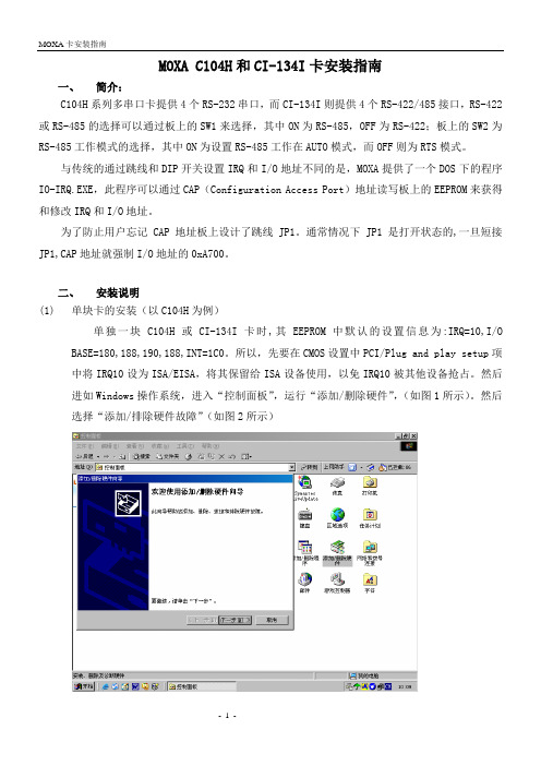
然后进如Windows操作系统,进入“控制面板”,运行“添加/删除硬件”,(如图1所示)。
然后选择“添加/排除硬件故障”(如图2所示)图1图2然后在“选择一个新硬件”对话框中选择“添加新硬件”(图3)图3在接下来的提示中选择“从列表选择硬件”(图4)图4然后选择“多串口卡“(图5),在弹出的对话框中选择“从软盘安装“,在地址栏中输入MOXA驱动程序所在路径(图6),确定后选择所插的MOXA卡型号(C104或CI-134I)(图7)图5图6图7再点击“下一步“后,系统自动安装至完毕。
然后重新启动系统即可。
CP-134U与CP-104UL测试报告
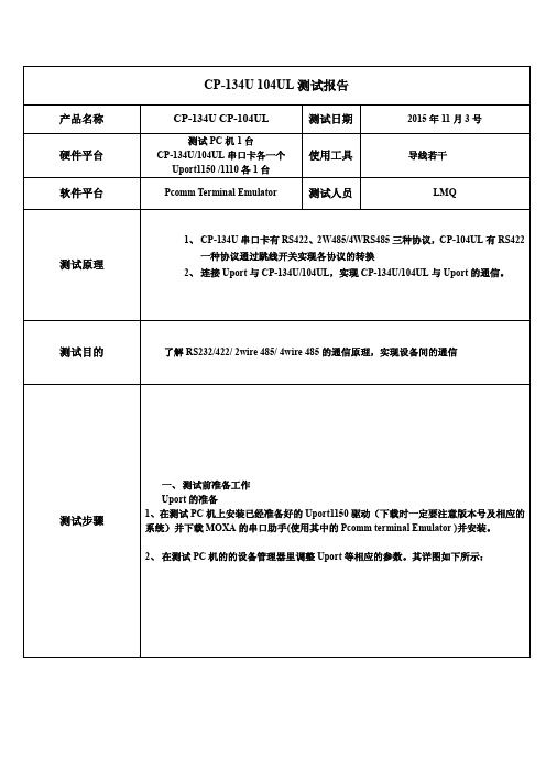
CP-134U 104UL测试报告产品名称CP-134U CP-104UL 测试日期2015年11月3号硬件平台测试PC机1台CP-134U/104UL串口卡各一个Uport1150 /1110各1台使用工具导线若干软件平台Pcomm Terminal Emulator 测试人员LMQ测试原理1、CP-134U串口卡有RS422、2W485/4WRS485三种协议,CP-104UL有RS422一种协议通过跳线开关实现各协议的转换2、连接Uport与CP-134U/104UL,实现CP-134U/104UL与Uport的通信。
测试目的了解RS232/422/ 2wire 485/ 4wire 485的通信原理,实现设备间的通信测试步骤一、测试前准备工作Uport的准备1、在测试PC机上安装已经准备好的Uport1150驱动(下载时一定要注意版本号及相应的系统)并下载MOXA的串口助手(使用其中的Pcomm terminal Emulator )并安装。
2、在测试PC机的的设备管理器里调整Uport等相应的参数。
其详图如下所示:(设置波特率)设置串口数据类型及串口号3、在设备管理器中将Uport1150设置成RS-422的通讯模式,波特率为9600,数据位为8,奇偶校验为None,停止位为1,流控为None;查看其映射的COM号(本实验中为COM4),记下以备使用。
CP-134U设置为RS422的通信1、将CP-134U安装到PC机的PCI插槽中,安装CP-134U的驱动程序。
安装好驱动后,进入设备管理器进行CP-134U的参数设置,2、波特率为9600,数据位为8,奇偶校验为None,停止位为1,流控为None;查看其映射的COM号(本实验中为COM5),记下以备使用。
3、调节CP-134U上的跳线开关,将其设置为RS422模式。
4、用导线制作连接线,将CP-134U的1(TXD-A)与Uport的4(RXD-A)连接,CP-134U的2(TXD+B)与Uport的3(RXD+B)连接,CP-134U的3(RXD+B)与Uport的2(TXD+B)连接,CP-134U的4(RXD-A)与Uport的1(TXD-A)连接。
MOXA CP118U板卡安装说明0222

MOXA CP-118U板卡安装说明1. MOXA CP-118U板卡的安装(Windows 2000)1. 将MOXA CP-118U板卡插入主板的PCI扩展槽中,重新启动计算机。
Windows 2000 将自动检测新硬件,接着系统将弹出【欢迎使用找到新硬件向导】对话框。
2. 在弹出的【欢迎使用找到新硬件向导】对话框中,点击“下一步”继续。
3. 选择“搜索适于我的设备的驱动程序(推荐)”,点击“下一步”继续。
4. 选择“指定一个位置”,点击“下一步”继续。
5. 插入驱动光盘,引导至光盘驱动器\CP-118U\Software\Win2K-XP-2003 \MXSER,点击“确认”继续。
6. 点击“下一步”,将所需要的驱动文件复制到操作系统中。
7. 在接下来的【没有找到数字签名】对话框中,系统提示将要安装的软件不包括Microsoft 数字签名,点击“是”继续安装。
8. 等待系统复制所需要的文件。
9. 在【完成找到新硬件向导】界面中,系统提示你已经完成板卡驱动的安装过程,并且能够显示安装MOXA板卡的型号。
点击“完成”按钮,继续其余的安装过程。
10. 接下来的【发现新硬件】对话框,提示您系统正在为板卡的多个串口分别安装驱动。
11. 【发现新硬件】对话框消失后,就表示安装过程全部结束。
板卡及其扩展的串口已经成功地安装了驱动程序。
打开【设备管理器】,可以看到新添加的多串口卡MOXA CP-118U,以及扩展出来的8个串口。
2. MOXA CP-118U板卡的设置1. MOXA CP-118U板卡的物理模型,如图所示。
2. MOXA CP-118U板卡上面包含3组切换器S1~S3,每组切换器包含8个切换开关DIP1~DIP8。
通过设置这3组切换器和切换开关,可以将板卡的串口类型设置为:RS-232、RS-422、4-wire RS-485或2-wire RS-485。
具体的设置方法请参考下表。
3. 目前,在D3-Air-2.0播控系统中普遍使用RS-422类型的串口控制方式。
多块ISA接口MOXA卡安装说明
多块ISA接口MOXA卡安装说明1、什么情况下可能会用到该说明?(1)、安装2块或2块以上ISA接口的MOXA卡。
(2)、缺省安装不成功, I/O口0xA700被占用,或有冲突的情况下。
(3)、WINNT或WIN98以外的操作系统。
2、需要准备些什么?(1)、具有足够多ISA插槽的工控机。
(2)、ISA接口的MOXA卡N块。
(目前最多成功安装过4块ISA接口的卡)(3)、MOXA驱动盘。
(4)、能够进入DOS系统的启动盘。
(5)、一个DOS下可以识别的分区。
(软驱、光驱、FAT或FAT32格式的硬盘分区)3、安装举例。
WIN2K系统下安装4块CI134I卡。
(1)、准备工作。
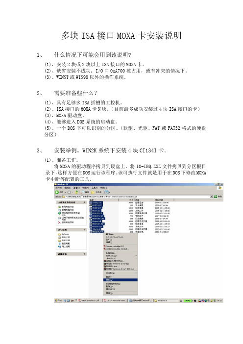
将MOXA的驱动程序拷贝到硬盘上。
将IO-IRQ.EXE文件拷贝到分区根目录下,这样方便在DOS运行该程序。
该可执行文件就是用于在DOS下修改MOXA 卡中断等配置的工具。
(2)、查看系统信息中硬件资源的应用和空闲情况。
查看其中的IRQs和I/O的占用情况,如上图中断10和中断11是空闲的。
(3)、重启进入BIOS,进入PnP/PCI Configerations,修改IRQ-10和IRQ-11为Legacy ISA。
按F10保存后退出。
(4)、关闭工控机电源,将其中一块MOXA卡装在工控机空余的ISA插槽上,短接该MOXA卡的JP1。
启动工控机,通过启动盘引导进入DOS,在DOS下运行IO-IRQ.EXE程序。
选择“Smartio/Industio ISA Family”按回车进入下一对话框。
输入“Configuration Access Port”地址的十六进制,对于JP1短接的情况下,该地址为A700;对于初次安装的板卡,他的缺省地址是180;对于其他已设置过中断的板卡,该地址是设置的I/O Address的始地址。
按回车进入下一对话框。
如果地址正确能找到该板卡则进入下一对话框进行板卡的配置。
如上图所示:Port index:是指串口的编号,CI-134卡共有4个串口,分别编号1~4。
MOXA串口服务器产品配置说明
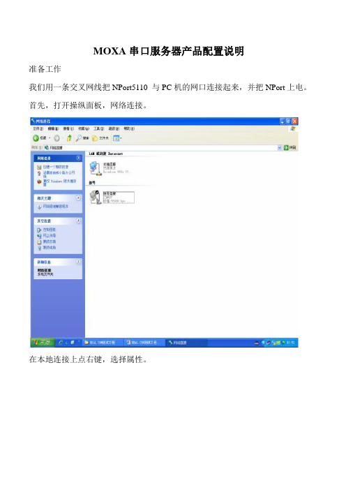
MOXA串口服务器产品配置说明准备工作我们用一条交叉网线把NPort5110 与PC机的网口连接起来,并把NPort上电。
首先,打开操纵面板,网络连接。
在本地连接上点右键,选择属性。
双击进入Internet协议(TCP/IP),点击“使用下面的IP地址”写入IP 地址与子网掩码,记住要与NPORT 的IP 地址在同一子网段内。
如NPORT 默认IP为192.168.127.254,255.255.255.0;就需要把PC 机的IP 地址设为192.168.127.XXX,255.255.255.0,最后一个数字不一致即可。
点击确定。
第二章:网络与串口参数配置搜索NPort打开NPort Administrator(能够在光盘的对应位置找到这个软件,安装好),点击Search,此时请确认网络防火墙已经关闭。
会搜索到我们的NPort5110,点击stop,停止搜索。
网络参数配置双击右边空白处的NPort 设备,会出现下列界面,点击选择Network 选项卡,点击Modify修改。
能够看到下列界面:我们能够在里面修改NPort的下列参数:IPAddress:IP地址。
Netmask:子网掩码。
Gateway:网关。
IP Configuration:能够配置为静态IP(Static),或者者为DHCP(动态IP)。
DNS Server1与2:DNS,域名解析服务器。
串口参数配置点击Serial选项卡,点击Modify修改,双击端口进去,能够看到下列界面:我们能够在里面修改下列参数:Baud Rate:波特率,NPort5000 系列只能支持标准波特率,如9600,115200bps 等。
Parity:校验。
None:无校验Even:偶校验。
Odd:奇校验。
Space:空。
Mark:标志。
Data Bits:数据位。
Stop Bits:停止位。
Flow Control:流量操纵。
None:无流量操纵。
XON/XOFF:软件流控。
Moxa PowerTrans 电源交换器 V3.1 快速安装指南说明书

P/N: 1802075280023*1802075280023*PT-7528 Series (24-Port Copper Models) Quick Installation GuideMoxa PowerTrans SwitchVersion 3.1, January 2021Technical Support Contact Information /support2021 Moxa Inc. All rights reserved.Package ChecklistThe Moxa PowerTrans switch is shipped with the following items. If any of these items are missing or damaged, please contact your customer service representative for assistance.• 1 Moxa PowerTrans switch•USB cable (Type A male to Type B male)•Protective caps for unused ports• 2 rackmount ears•Quick installation guide (printed)•Warranty cardPanel Layout1.System status LEDs2.Ethernet port LEDs3.Fast Ethernet port4.Fiber Ethernet interface module slotB console port6.10-pin terminal block for power inputs, and relay output7.Rack mounting kit8.Grounding screwB storage port (ABC-02-USB-T)10.Reset buttonDimensions; unit = mm (in)Fiber Ethernet Interface ModulesRack MountingUse six screws to attach the PT switch to a standard rack. Rack Mounting KitPT-7528 Side ViewNOTE Two additional rack-mount ears can be ordered as an option.Use them to secure the rear of the chassis in high-vibration environments.Wiring RequirementsGrounding the Moxa PowerTrans SwitchGrounding and wire routing help limit the effects of noise due to electromagnetic interference (EMI). Run the ground connection from the ground screw to the grounding surface prior to connecting devices. Wiring the Power InputsThe PT-7528 switches support dual redundant power supplies: Power Supply 1 (PWR1) and Power Supply 2 (PWR2). The connections for PWR1, PWR2, and the RELAY are located on the terminal block. The front view of the terminal block connectors are shown below.Wiring the Relay ContactEach PT-7528 switch provides two types of relay output, at the user’s option. Refer below for detailed instructions on how to connect the wires to the terminal block connector, and how to attach the terminal block connector to the terminal block receptor.Normal contact statewithou t powerapplied to deviceThe relay contact is used to detect user-configured events. Two wires are attached to the relay pins. The PT-7528 provides normal open and normal closed circuits at the user’s option. For pin definitions refer to the table below:Relay pin connection Power on state Event triggerPin 4 and 6 Closed circuitOpen circuitPin 8 and 6 Open circuit Closed circuit Wiring the Redundant Power InputsEach PT switch has two sets of power inputs: power input 1 and power input 2.STEP 1: Insert the dual set positive/negative DC wires into PWR1 and PWR2 terminals (+ → pins 1, 7; - → pins 3, 9), or insert the L/N AC wires into PWR1 and PWR2 terminals (L → pins 1, 7; N → pins 3, 9). STEP 2: To keep the DC or AC wires from pulling loose, use a screwdriver to tighten the wire-clamp screws on the front of the terminal block connector.Ethernet PortsFast Ethernet RJ45 Twisted-Pair CablingPT-7528 series Ethernet switches are equipped with many10/100BaseTX ports that allow connection to standard CAT-5 STP cables with RJ45 male connectors.PT-7528 series products feature auto-negotiation, auto-polarity, and auto-crossover functions. For high EMC environment applications, we suggest using shielded twisted-pair cables to avoid EMC interference and to retain compliance with the IEEE 1613 standard.Gigabit Ethernet 1000BaseTX CablingThe IEEE 802.3ab Gigabit Ethernet standard defines 1000 Mbps Ethernet communications over distances of up to 100 meters using all 4 pairs in category 5 (or higher) balanced unshielded twisted-pair cabling. For wiring guidelines, system designers and integrators should refer to the Telecommunications Industry Association (TIA) TIA/EIA-568-A wiring standard that characterizes minimum cabling performance specifications required for proper Gigabit Ethernet operation. To ensure reliable, error-free data communication, new and pre-existing communication paths should be verified for TIA/EIA-568-A compliance. •Data cable lengths should be as short as possible, ideally limited to3 m (10 ft) in length. Copper data cables should not be used forinter-building communications.•Power and data cables should not be run in parallel for long distances, and should be installed in separate conduits. Power and data cables should intersect at 90° angles when necessary toreduce inductive coupling.•Optionally, shielded/screened cabling can be used. The cable shield should be grounded at one single point to avoid the generation of ground loops.USB Console ConnectionThe PT-7528 series has one USB console port (type B connector), located on the top panel. Use the USB cable (provided in the product package) to connect the PT-7528’s console port to your PC’s USB port and install the USB driver (available on the Moxa website) on your PC. You may then use a console terminal program, such as Moxa PComm Terminal Emulator, to access the PT-7528’s console configuration utility.USB Console Port (Type B Connector) PinoutsPinDescription1 D- (Data-)2 VCC (+5V)3 D+ (Data+)4 GND (Ground)USB Storage ConnectionThe PT-7528 series has one USB storage port (type A connector) on the front panel. Use Moxa’s ABC-02-USB-T automatic backup configurator to connect the PT-7528’s USB storage port for configuration backup, firmware upgrade, or system log file backup.ABC-02-USB InstallationPlug the ABC-02-USB into the USB storage port of the Moxa PT-7528 series. We suggest attaching the ABC-02-USB to a wall with an M4 screw.USB Storage Port (Type A Connector) PinoutsPinDescription 1 VCC (+5 V) 2D- (Data-) 3D+ (Data+) 4 GND (Ground) The Reset ButtonDepress the Reset button for five continuous seconds to load thefactory default settings. Use a pointed object, such as a straightened paper clip or toothpick, to depress the Reset button. When you do so, the STATE LED will start to blink about once per second. Continue to depress the STATE LED until it begins blinking more rapidly; thisindicates that the button has been depressed for five seconds and you can release the Reset button to load factory default settings.NOTE DO NOT power off the switch when loading default settings LED Indicators LEDColorState DescriptionSTATE GREEN On System has passed self-diagnosis test on boot-up and is ready to run.Blinking • 1 blink every sec: The switch is being reset.• 1 blink every 2 sec:The switch is connected to the ABC-02-USB.RED On The system failed self-diagnosis on boot-up.• RAM Test Fail / System Info. Read Fail /Switch Initial Fail / PTP PHY Error. (+ Green MSTR lit on : HW FAIL)• FW Checksum Fail / Uncompress Fail. (+Green Coupler lit on: SW FAIL)LED Color State DescriptionFAULT RED OnOne of the following situations exists:•The signal contact is open.•ABC Loading/Saving Failure.•The port has been disabled because theingress multicast and broadcast packetsexceed the ingress rate limit.•Incorrect loop connection in a single switch.•Invalid Ring port connection.Off The system is operating normally.PWR1 AMBER OnPower is being supplied to the main module’spower input PWR1.OffPower is not being supplied to the mainmodule’s power input PWR1.PWR2 AMBER OnPower is being supplied to the main module’spower input PWR2.OffPower is not being supplied to the mainmodule’s power input PWR2.MSTR/ HEAD GREENOnOne of the following situations exists:•The switch is set as the Master of the TurboRing, or as the Head of the Turbo Chain.•POST H.W. Fail (+Stat on and Faultblinking).BlinkingOne of the following situations exists:•The switch has become the Ring Master ofthe Turbo Ring.•The switch has become the Head of theTurbo Chain after the Turbo Ring or theTurbo Chain went down.•The switch is set as a member of the TurboChain and the corresponding chain port isdown.OffOne of the following situations exists:•The switch is not the Master of this TurboRing.•This switch is set as a member of the TurboChain.CPLR/ TAIL GREENOnOne of the following situations exists:•The switch’s coupling function is enabled toform a back-up path.•The switch is set as the Tail of the TurboChain.•POST S.W. Fail (+Stat on and Faultblinking)BlinkingOne of the following situations exists:•Turbo Chain is down.•The switch is a member of the Turbo Chainand the corresponding chain port is down.OffOne of the following situations exists:•This switch has disabled the couplingfunction.•This switch is a member of the TurboChain.LED Color State DescriptionFAULT + MSTR/HEAD + CPLR/TAILRotateBlinkingSequentiallyABC-02-USB is importing/exporting files.STATE +FAULT + MSTR/HEAD + CPLR/TAIL Blinking2 blinks per sec: The switch is beingdiscovered/located by MXview.Ports 1 to 24 GREENOn Port’s 100 Mbps link is activeBlinking Data is transmitting at 100 MbpsOff Port’s link is inactiveAMBEROn Port’s 10 Mbps link is activeBlinking Data is transmitting at 10 MbpsOff Port’s link is inactiveM1 Ports 1 to 4 GREENOn Port’s highest speed link is activeBlinking Data is transmitting at the highest speedOff Port’s link is inactiveAMBEROn Port’s non-highest speed link is activeBlinking Data is transmitting at non-highest speedOff Port’s link is inactiveSpecificationsTechnologyStandards IEEE 802.3 for 10BaseTIEEE 802.3u for 100BaseT(X) and 100BaseFXIEEE 802.3ab for 1000BaseT(X)IEEE 802.3z for 1000BaseXIEEE 802.3x for Flow ControlIEEE 802.1D-2004 for Spanning Tree ProtocolIEEE 802.1w for Rapid STPIEEE 802.1s for Multiple Spanning Tree ProtocolIEEE 802.1Q for VLAN TaggingIEEE 802.1p for Class of ServiceIEEE 802.1X for AuthenticationIEEE 802.3ad for Port Trunk with LACP Protocols IGMP v1/v2, GMRP, GVRP, SNMPv1/v2c/v3, DHCPServer/Client, BootP, TFTP, SNTP, SMTP, RARP,RMON, HTTP, HTTPS, Telnet, SSH, Syslog, DHCPOption 66/67/82, EtherNet/IP, Modbus/TCP, LLDP,IEEE 1588 PTP V2, IPv6, NTP Server/Client, MMS MIB MIB-II, Ethernet-like MIB, P-BRIDGE MIB,Q-BRIDGE MIB, Bridge MIB, RSTP MIB,RMON MIB Groups 1, 2, 3, 9Flow control IEEE 802.3x flow control, back pressure flowcontrolInterfaceFast Ethernet 10/100BaseT(X) or 100BaseFX (SC/ST connector) Gigabit Ethernet 10/100/1000BaseT(X), 1000BaseSX/LX/LHX/ZX(SFP slot, LC connector)Console Port USB-serial console (Type B connector)Storage port USB storage port (Type A connector)System LED Indicators STAT, PWR1, PWR2, FAULT, MSTR/HEAD, CPLR/TAILAlarm Contact One relay output with current carrying capacity of3 A @ 30 VDC or 3 A @ 240 VACOptical Fiber (100BaseFX)Distance Multi-mode:0 to 5 km, 1300 nm (50/125μm, 800 MHz*km)0 to 4 km, 1300 nm (62.5/125μm, 500 MHz*km)Single mode:0 to 40 km, 1310 nm (9/125μm, 3.5 PS/(nm*km)) Min. TX Output Multi-mode: -20 dBm; Single mode: -5 dbm Max. TX Output Multi-mode: -10 dBm; Single mode: 0 dbmRX Sensitivity Multi-mode: -32 dBm; Single mode: -34 dbm PowerInput Voltage WV: 24/48 VDC (18 to 72 V)HV: 110/220 VDC/VAC (88 to 300 VDC and 85 to264 VAC)Input Current Max. 0.741 A @ 24 VDCMax. 0.364 A @ 48 VDCMax. 0.147/0.077 A @ 110/220 VDCMax. 0.283/0.19 A @ 110/220 VACInrush Current WV model:HV model: 1.51 A @ 24 VDC (0.1 ms), 1.80 A @ 48 VDC (0.1 ms) 7.06 A @ 110 VDC (0.1 ms), 15.14 A @ 220 VDC (0.1 ms)Physical CharacteristicsHousing IP40 protection, metal caseDimensions(W x H x D)440 x 44 x 325 mm (17.32 x 1.73 x 12.76 in) Weight 4900 gInstallation 19” rack mountingStandards and CertificationsSafety UL 508Power Automation IEC 61850-3, IEEE 1613Road Traffic NEMA TS2Rail Traffic EN 50121-4EMI FCC Part 15 Subpart B Class A, EN 55032 class A Environmental LimitsOperating Temp. -40 to 85°C (-40 to 185°F)Cold start of min. 100 VAC at -40°CStorage Temp. -40 to 85°C (-40 to 185°F)Ambient RelativeHumidity.5 to 95% (non-condensing)WarrantyWarranty Period 5 yearsDetails See /warrantyRack Mounting Instructions1.Elevated Operating Ambient: If installed in a closed or multi-unit rack assembly, the operating ambient temperature of the rack environment may be greater than room ambient. Therefore,consideration should be given to installing the equipment in anenvironment compatible with the maximum ambient temperature (Tma) specified by the manufacturer.2.Reduced Air Flow: Installation of the equipment in a rack shouldbe such that the amount of air flow required for safe operation of the equipment is not compromised.3.Mechanical Loading: Mounting of the equipment on the rackshould be such that a hazardous condition is not achieved due to uneven mechanical loading.4.Circuit Overloading: Consideration should be given to theconnection of the equipment to the supply circuit and the effectthat overloading of the circuits might have on overcurrentprotection and supply wiring. Appropriate consideration ofequipment nameplate ratings should be used when addressing this concern.5.Reliable Grounding: Reliable grounding of rack-mountedequipment should be maintained. Particular attention should begiven to supply connections other than direct connections to thebranch circuit (e.g., use of power strips).NOTE The rackmount ears can be equipped on the front or rear of the PT-7528 switch.Restricted Access Locations•This equipment is intended to be used in Restricted Array Access Locations, such as a computer room, withaccess limited to SERVICE PERSONAL or USERS whohave been instructed on how to handle the metalchassis of equipment that is so hot that special protection may beneeded before touching it. The location should only be accessible with a key or through a security identity system.•External metal parts of this equipment are extremely hot!! Before touching the equipment, you must take special precautions toprotect your hands and body from serious injury.Power Connection WarningYou should always connect both power supplies when using this device, and disconnect both power supplies when this device is not in use. If only one power supply is connected, you could receive a hazardous electric shock by touching the unconnected terminals of the other power supply.All power connection wiring must be done by a qualified electrician and follow the National Electrical Code, ANSI/NFPA 70, and Canadian Electrical Code, Part I, CSA C22.1. An IEC certified or UL listed single-phase type circuit-breaker, rated for a maximum of 20 A, should be installed between main circuit and the device.- 11 -。
MOXA ISA非智能卡简易安装测试向导-SCO
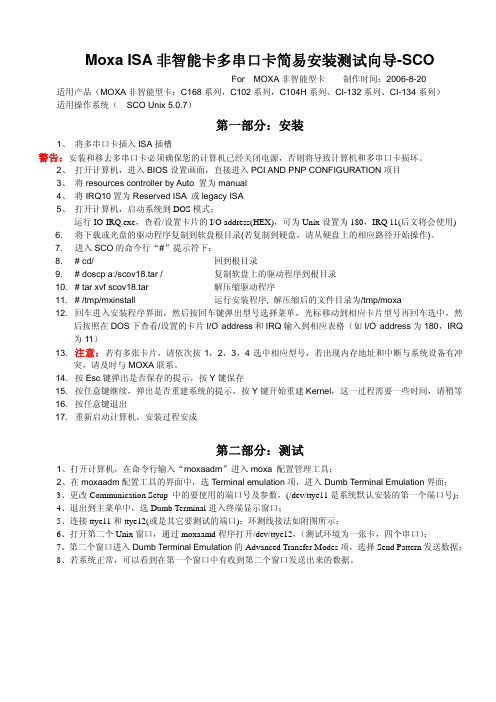
Moxa ISA非智能卡多串口卡简易安装测试向导-SCOFor MOXA非智能型卡制作时间:2006-8-20 适用产品(MOXA非智能型卡:C168系列,C102系列,C104H系列、CI-132系列、CI-134系列)适用操作系统( SCO Unix 5.0.7)第一部分:安装1、将多串口卡插入ISA插槽警告:安装和移去多串口卡必须确保您的计算机已经关闭电源,否则将导致计算机和多串口卡损坏。
2、打开计算机,进入BIOS设置画面,直接进入PCI AND PNP CONFIGURATION项目3、将resources controller by Auto 置为manual4、将IRQ10置为Reserved ISA 或legacy ISA5、打开计算机,启动系统到DOS模式;运行IO-IRQ.exe,查看/设置卡片的I/O address(HEX),可为Unix设置为180,IRQ 11(后文将会使用)6. 将下载或光盘的驱动程序复制到软盘根目录(若复制到硬盘,请从硬盘上的相应路径开始操作)。
7. 进入SCO的命今行“#”提示符下:8. # cd/ 回到根目录9. # doscp a:/scov18.tar / 复制软盘上的驱动程序到根目录10. # tar xvf scov18.tar 解压缩驱动程序/tmp/mxinstall 运行安装程序, 解压缩后的文件目录为/tmp/moxa#11.12. 回车进入安装程序界面,然后按回车键弹出型号选择菜单,光标移动到相应卡片型号再回车选中,然后按照在DOS下查看/设置的卡片I/O address和IRQ输入到相应表格(如I/O address为180,IRQ 为11)13. 注意:若有多张卡片,请依次按1,2,3,4选中相应型号,若出现内存地址和中断与系统设备有冲突,请及时与MOXA联系。
14. 按Esc键弹出是否保存的提示,按Y键保存15. 按任意键继续,弹出是否重建系统的提示,按Y键开始重建Kernel,这一过程需要一些时间,请稍等16. 按任意键退出17. 重新启动计算机,安装过程安成第二部分:测试1、打开计算机,在命令行输入“moxaadm”进入moxa 配置管理工具;2、在moxaadm配置工具的界面中,选Terminal emulation项,进入Dumb Terminal Emulation界面;3、更改Communication Setup 中的要使用的端口号及参数,(/dev/ttye11是系统默认安装的第一个端口号);4、退出到主菜单中,选Dumb Terminal进入终端显示窗口;5、连接ttye11和ttye12(或是其它要测试的端口);环测线接法如附图所示;6、打开第二个Unix窗口,通过moxaamd程序打开/dev/ttye12,(测试环境为一张卡,四个串口);7、第二个窗口进入Dumb Terminal Emulation的Advanced Transfer Modes项,选择Send Pattern发送数据;8、若系统正常,可以看到在第一个窗口中有收到第二个窗口发送出来的数据。
Moxa多串口卡--CP134U 说明书
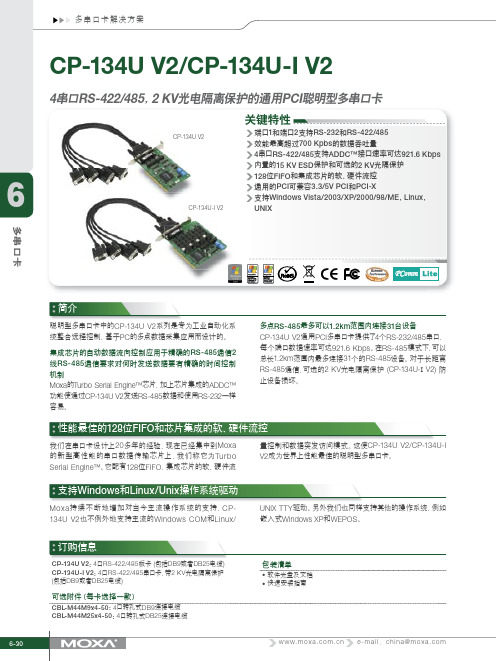
6-30 e-mail :china@CP-134U V2:4口RS-422/485板卡 (包括DB9或者DB25电缆)CP-134U-I V2:4口RS-422/485串口卡,带2 KV 光电隔离保护 (包括DB9或者DB25电缆)订购信息包装清单• 软件光盘及文档• 快速安装指南可选附件(每卡选择一款)CBL-M44M9x4-50:4口转孔式DB9连接电缆CBL-M44M25x4-50:4口转孔式DB25连接电缆关键特性4RS-422/485 2 KV PCI 简介CP-134U V2CP-134U-I V2性能最佳的128位FIFO 和芯片集成的软、硬件流控支持Windows 和Linux/Unix 操作系统驱动我们在串口卡设计上20多年的经验,现在已经集中到Moxa 的新型高性能的串口数据传输芯片上,我们称它为TurboSerial Engine™。
它配有128位FIFO ,集成芯片的软、硬件流量控制和数据突发访问模式。
这使CP-134U V2/CP-134U-IV2成为世界上性能最佳的聪明型多串口卡。
聪明型多串口卡中的CP-134U V2系列是专为工业自动化系统整合远程控制,基于PC 的多点数据采集应用而设计的。
集成芯片的自动数据流向控制应用于精确的RS-485通信2线RS-485通信要求对何时发送数据要有精确的时间控制机制Moxa 的Turbo Serial Engine™芯片,加上芯片集成的ADDC™功能使通过CP-134U V2发送RS-485数据和使用RS-232一样容易。
多点RS-485最多可以1.2km 范围内连接31台设备CP-134U V2通用PCI 多串口卡提供了4个RS-232/485串口,每个端口数据速率可达921.6 Kbps 。
在RS-485模式下,可以总长1.2km 范围内最多连接31个的RS-485设备。
对于长距离RS-485通信,可选的2 KV 光电隔离保护 (CP-134U-I V2) 防止设备损坏。
MOXA 串口服务器中文使用文档

MOXA串口联网服务器NPORT 5130 特点- 以太网口支持100/10M自适应,串口支持RS-422,RS-485(2w/4w)- 低成本、信用卡大小- 支持Windows/Linux COM串口驱动程序模式- 提供包括TCP Server、TCP Client、UDP Server/Client和Ethernet Modem 在内的不同socket操作模式- 无需PC、可通过网络连接两个串口设备的对等连接模式- 易于使用、可用于批量安装的Windows工具- 所有信号内置15 KV突波保护- 支持网络管理协议SNMP MIB-II- 可通过网络Web/Telnet进行配置MOXA针对串口联网服务器开发了软件NPort Administrator,方便用户配置,下面我就着重讲如何用NportAdministration 配置NPORT产品,图一1、NPORT 5130提供多种操作模式,例如:Realcom模式,Tcp server模式,Tcp client模式,Udp模式。
图二2、配置方法:2.1、安装NPORT administration 软件。
2.2、打开软件,如图:图三点击Search,可以搜索到局域网中所有的NPORT设备,包括和主机IP不同网段的NPORT设备。
搜索到设备如下图:图四如图可以显示设备的型号,MAC地址,IP地址,以及设备的名称。
(默认IP:192.168.127.254)2.3、基本设置界面介绍选中要配置的设备,点击右键——Configuer,或者是双击,进入设备配置界面,如图:图五如图五,Basic界面可以设置设备的名称,设备的时钟(默认读取主机时钟),以及登陆设备的方式。
(提醒:必须勾选Modofy才能对配置进行修改,否则只能对查看配置)2.4、网络设置页面介绍图六如图六,Network界面配置Ip地址相关信息。
设置串口联网服务器IP地址与主机IP为同一个网段。
MOXA串口服务器设置步骤
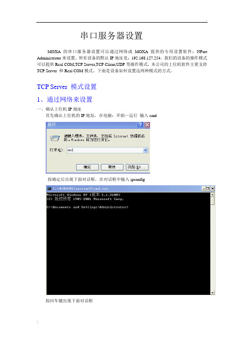
MOXA串口服务器的Real COM模式设置只能通过MOXA的专用软件来设置,它是在操作系统上虚拟一个串口,在硬件管理里是无法找到的,下面是基本设置,前期设置跟TCP Serverm模式设置是一样的,就是最后一步操作模式选择Real COM模式,设备一般默认是Real COM模式,所以一般不设也没关系的。设置完成后还需要虚拟串口。
点击进入Serial Parameters进入下面界面,设置串口波特率,这个波特率要跟你的上位机软件设置成一样。
点击OK进入下面界面
点住主对话框里的NPort 5110,鼠标右击选择Enable(激活),在选择上面对话框的Apply保存,设置完毕。
----------------------------------------------------------------------------------------------------------------------
串口服务器设置
MOXA的串口服务器设置可以通过网络或MOXA提供的专用设置软件:NPort Administrator来设置,所有设备的默认IP地址是:192.168.127.254。我们的设备的操作模式可以提供Real COM,TCP Server,TCP Client,UDP等操作模式,本公司的上位机软件主要支持TCP Server和Real COM模式,下面是设备如何设置这两种模式的方式。
前
点击后出现的界面
一般默认是Real COM Mode,所以直接点击OK好了。
点击OK
鼠标点住COM Mapping右击Add Target
点击前
点击后
选中对话框里的No 1前的小框框,点击OK,出现如下界面。
moxa卡驱动安装及测试
linux下 moxa串口卡驱动安装及测试步骤(CP-118EL)把串口卡自带光盘放入光驱把一下路径下的驱动文件复制到服务器的根目录下:cp /media/MSB V2.8/CP-118EL Series/Software/Linux 2.6/x86/driv_linux_smart_v1.15_build_09103015.tgz / (media为光盘驱动器的mount路径)[root@localhost ~]# cd / (进入根目录)[root@localhost /]# tar -xzvf driv_linux_smart_v1.15_build_09103015.tgz (解压驱动程序)[root@localhost /]# cd mxser (进入解压后的目录)[root@localhost mxser]# ./mxinstall (执行驱动程序安装)[root@localhost mxser]# cd driver (进入driver目录)[root@localhost driver]# ./msmknod (创建设备链接)MOXA Smartio Family Multiport Board Make Node Utility.Please input device major number for mxser(Enter for default=30):Please input device major number for mxnpcie(Enter for default=31):mxser major= 30mxnpcie major= 31Please input callout device major number for mxser(Enter for default=35):Please input callout device major number for mxnpcie(Enter for default=34):mxser major= 35mxupcie major= 34Please input total board number (1-4, Enter for default=1):boards= 1Make special node...Make tty device.../dev/ttyM0 /dev/cum0 0/dev/ttyMUE0 /dev/cumue0 0/dev/ttyM1 /dev/cum1 1/dev/ttyMUE1 /dev/cumue1 1/dev/ttyM2 /dev/cum2 2/dev/ttyMUE2 /dev/cumue2 2/dev/ttyM3 /dev/cum3 3/dev/ttyMUE3 /dev/cumue3 3/dev/ttyM4 /dev/cum4 4/dev/ttyMUE4 /dev/cumue4 4/dev/ttyM5 /dev/cum5 5/dev/ttyMUE5 /dev/cumue5 5/dev/ttyM6 /dev/cum6 6/dev/ttyMUE6 /dev/cumue6 6/dev/ttyM7 /dev/cum7 7/dev/ttyMUE7 /dev/cumue7 7测试步骤:使用串口线连接两台服务器的串口1(使用直连串口线,不要使用交叉串口线)[root@localhost]# cd /mxser/utility/term (进入term测试目录)[root@localhost term]# ./msterm (执行msterm程序进入测试环节)进入界面,更改 Communication Setup 中的/dev/ttyS0 为/dev/ttyM0按ESC键回到主菜单,选择 Dumb Terminal 进入终端窗口在第二台服务器上面重复以上步骤,并在msterm测试菜下选择 Advaced Transfer Modes,点击Send Pattern 发送数据。
Moxa CP-102E 102EL 2-port RS-232 PCI Express 卡说明说明
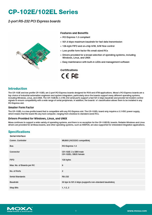
CP-102E/102EL Series2-port RS-232PCI Express boardsFeatures and Benefits•PCI Express1.0compliant•921.6kbps maximum baudrate for fast data transmission•128-byte FIFO and on-chip H/W,S/W flow control•Low-profile form factor fits small-sized PCs•Drivers provided for a broad selection of operating systems,includingWindows,Linux,and UNIX•Easy maintenance with built-in LEDs and management softwareCertificationsIntroductionThe CP-102E and low-profile CP-102EL are2-port PCI Express boards designed for POS and ATM applications.Moxa’s PCI Express boards are a top choice of industrial automation engineers and system integrators,particularly since the boards support many different operating systems, including Windows,Linux,and UNIX.The CP-102E/EL’s2RS-232serial ports support a fast921.6kbps baudrate and provide full modem control signals to ensure compatibility with a wide range of serial peripherals.In addition,the boards’x1classification allows them to be installed in any PCI Express slot.Smaller Form FactorThe CP-102EL is a low-profile board that is compatible with any PCI Express slot.The CP-102EL board only requires a3.3VDC power supply, which means that the board fits any host computer,ranging from shoebox to standard-sized PCs.Drivers Provided for Windows,Linux,and UNIXMoxa continues to support a wide variety of operating systems,and there is no exception for the CP-102E/EL boards.Reliable Windows and Linux drivers are provided for all Moxa boards,and other operating systems,such as WEPOS,are also supported for embedded integration applications.SpecificationsSerial InterfaceComm.Controller MU860(16C550C compatible)Bus PCI Express1.0Connector CP-102E:2x DB9maleCP-102EL:DB25femaleFIFO128bytesMax.No.of Boards per PC8No.of Ports2Serial Standards RS-232Baudrate50bps to921.6kbps(supports non-standard baudrates)Stop Bits1,1.5,2Parity None,Even,Odd,Space,MarkFlow Control None,RTS/CTS,XON/XOFFSerial SignalsRS-232TxD,RxD,RTS,CTS,DTR,DSR,DCD,GNDSerial Software FeaturesWindows Drivers DOS,Windows95/98/ME/NT/2000,Windows XP/2003/Vista/2008/7/8/8.1/10(x86/x64),Windows2008R2/2012/2012R2(x64),Windows Embedded CE5.0/6.0,Windows XPEmbeddedLinux Drivers Linux kernel2.4.x,Linux kernel2.6.x,Linux kernel3.x,Linux kernel4.x,Linux kernel5.x UNIX Drivers QNX6,Solaris10,UnixWare7,SCO OpenServer5,SCO OpenServer6Power ParametersInput Current CP-102E:520mA@3.3VDCCP-102EL-DB9M:552mA@3.3VDCPhysical CharacteristicsDimensions CP-102E:85.04x100mm(3.35x3.94in)CP-102EL-DB9M:67.21x100mm(2.65x3.94in)LED InterfaceLED Indicators Built-in Tx,Rx LEDs for each portEnvironmental LimitsOperating Temperature0to55°C(32to131°F)Storage Temperature(package included)-20to85°C(-4to185°F)Ambient Relative Humidity5to95%(non-condensing)Standards and CertificationsEMC EN55032/24EMI CP-102E:CISPR32,FCC Part15B Class ACP-102EL-DB9M:CISPR32,FCC Part15B Class BEMS IEC61000-4-2ESD:Contact:4kV;Air:8kVIEC61000-4-3RS:80MHz to1GHz:3V/mIEC61000-4-4EFT:Power:1kV;Signal:0.5kVIEC61000-4-5Surge:Power:2kVIEC61000-4-6CS:150kHz to80MHz:3V/m;Signal:3V/mIEC61000-4-8PFMFDeclarationGreen Product RoHS,CRoHS,WEEEMTBFTime4,947,552hrsStandards Telcordia(Bellcore)Standard TR/SRWarrantyWarranty Period5yearsDetails See /warrantyPackage ContentsDevice1x CP-102E/102EL Series serial boardDocumentation1x document and software CD1x quick installation guide1x warranty cardDimensionsCP-102E CP-102ELOrdering InformationModel Name Serial Standards No.of Serial Ports Included Cable Form Factor CP-102EL-DB9M RS-2322CBL-M25M9x2-50Low profile CP-102E RS-2322–Standard board Accessories(sold separately)Brackets1490000001000Bracket for DB44packApplicable Models:CP-102EL-DB9M3095010000007Bracket for DB44packApplicable Models:CP-102EL-DB9MCablesCBL-F9M9-150DB9female to DB9male serial cable,1.5mCBL-F9M9-20DB9female to DB9male serial cable,20cmCBL-M25M9x2-50M25to2x DB9male serial cable,50cm©Moxa Inc.All rights reserved.Updated Mar06,2020.This document and any portion thereof may not be reproduced or used in any manner whatsoever without the express written permission of Moxa Inc.Product specifications subject to change without notice.Visit our website for the most up-to-date product information.。
MOXA TCC-100系列快速安装指南版本12.2,2021年9月说明书

P/N: 180200100031B*180200100031B*TCC-100 Series Quick Installation GuideVersion 12.2, September 2021Technical Support Contact Information/support2021 Moxa Inc. All rights reserved.OverviewMany important devices used in today’s industrial environment are still designed for use with an RS-232 interface. The reason is due in part to tradition, and in part to convenience. RS-232 hardware is relatively easy to design, and the devices can be readily connected to most PCs. The drawback is that RS-232 is a point-to-point interface, and it imposes a distance limitation of only 15 meters between the device and the computer.To overcome these limitations, many users employ RS-232 to RS-422/485 converters, allowing RS-232 devices to connect to an industrial RS-422 or RS-485 network and transmit data over distances up to 1.2 km. The RS-422/485 standards overcome the distance limitation by using a differential signal for transmitting data and control signals. Transmission distance and multi-drop connections are not the only issues of importance for industrial applications. In addition, housing, wiring, power supply, and over-surge protection are also serious concerns.The TCC-100I and TCC-100I-T models come with isolation protection for users who need an industrial grade interface conversion product to extend RS-232 transmission distance and increase networking capability. The superior industrial application design, which includes DIN-rail mounting, terminal block wiring, an external terminal block power, and optical isolation for system protection, makes the TCC-100 Series suitable for use in critical industrial environments. Your RS-232 devices can be used as part of an industrial RS-422/485 network, but without any hardware or software changes.RTS/CTS RS-422 Handshaking SignalsThe TCC-100 Series supports RS-422 handshaking signals. The RTS and CTS signals help solve the RS-422 signal handshaking problem and reduce data transmission errors.Built-in RS-485 ADDC? IntelligenceADDC™ (Automatic Data Direction Control) is a Moxa technology that uses a clever hardware solution to manage RS-485’s data flow control problem. ADDC™ is a hardware data flow solution that automatically senses and controls data direction, making the handshaking signal method unnecessary.IsolationMoxa’s electrical isolation technology uses two photo couplers to create a gap in each electrical signal. One photo coupler transforms the electrical signal into a light signal, which is transmitted across a small gap, and then the other photo coupler transforms the light back into an electrical signal. In this way, the two electrical circuits are completely isolated from each other, limiting the damage that could otherwise be caused by ground loops in the electrical signal.Reverse Power ProtectionThe Reverse Power Protection feature provides extra protection against accidentally connecting the power cables to the wrong terminal. The converter is designed to automatically detect which power wire is positive and which is negative, and then adjust the power supply accordingly.DIP Switch Selectable TerminatorFor many products of this type, the termination resistor is set by a jumper located inside the product’s casing, so that the user must open the casing to disable or change the resistor’s strength. Moxa offers a better solution. The TCC-100 Series’ terminator is configured with a DIP switch located on the outside of the converter’s casing.Auto Baudrate DetectionThe TCC-100 Series incorporates a method for automatically detecting the serial signal’s baudrate by hardware. This is an extremely convenient feature for the user. Even if a device’s baudrate changes, the signal will still be transmitted through the RS-232 to RS-422/485 converter without any problem.Product Features•RS-232 to RS-422 conversion with RTC/CTS support•RS-232 to 2/4-wire RS-485 conversion•Detachable wall and DIN-rail mounting for easy RS-422/485 wiring •PWR, Tx, and Rx LEDs• 2 kV isolation (TCC-100I/TCC-100I-T) for both power and RS-422/485 signals•Operating temperature:TCC-100/100I: -20 to 60°C (-4 to 140°F)TCC-100-T/100I-T: -40 to 85°C (-40 to 185°F)Package ChecklistBefore installing the Moxa TCC-100, verify that the package contains the following items:•TCC-100/100I media converter•DK-35A: DIN-rail mounting kit•Power jack to 3-pin terminal block adaptor•User’s manual (this document)•Warranty cardNote: Please notify your sales representative if any of the above items are missing or damaged.Product Specifications Communication RS-232 SignalSupports Tx, Rx, RTS, CTS;Female DB9 interfaceRS-422/485 Signal Terminal block connector (DIP Switchselectable)4-wire RS-422 (with RTS/CTS), up to 10 nodes(1.2 km)4-wire RS-485: up to 32 nodes (1.2 km)2-wire RS-485: up to 32 nodes (1.2 km)RS-485 Data Direction ControlADDC™Baudrate 50 bps to 921.6 KbpsESD Protection 15 kVIsolation 2 kV (TCC-100I/TCC-100I-T) for both powerand signalEnvironmental LimitsOperating Temperature TCC-100/TCC-100I:-20 to 60°C (-4 to 140 °F)TCC-100-T/TCC-100I-T:-40 to 85°C (-40 to 185 °F)Storage Temperature -40 to 85°C (-40 to 185°F)Humidity 5 to 95 %RHPower RequirementsInput Power Voltage External Power 12-48 VDC, terminal block Reverse Power ProtectionProtects against V+/V- reversalOver Current ProtectionProtects against 2 signals shorted together Power Consumption TCC-100/TCC-100-T: 85 mA @ 12 VTCC-100I/TCC-100I-T: 150 mA @ 12 VPhysical CharacteristicsDimensions 67 × 100 × 22 mm (without ears)90 × 100 × 22 mm (with ears)Housing AluminumPlug-In Screw Terminal Block#22 to #16 AWGWeight 148±5 gRegulatory Approvals CE, FCC (Class A), UL-60950-1SchematicLED IndicatorsThe TCC-100’s top panel contains three LED indicators, as described in the following table: LEDNameLED Function PWRRed indicates the power is on. Green indicates the TCC-100 isreceiving data from the RS-232port.Yellow indicates the TCC-100 isreceiving data from the RS-422/485 port.Hardware InstallationInstalling the TCC-100 involves six straightforward steps:•STEP 1: Set the DIP switches •STEP 2: Attach the power supply •STEP 3: Wire the terminal block •STEP 4: Attach the RS-232 converter •STEP 5: Test the connection • STEP 6: Choose a placement optionSTEP 1: Set the DIP SwitchesThe DIP switches on the TCC100/100I are used to set the signaltransmission mode and to enable or disable the termination resistor. You can configure the converter for either RS-422 or RS-485transmission mode. Your program and serial port should be set to match the converter’s settings.SW1— Switch 1 selects RS-422 or RS-485 mode. The default is “Off”for RS-485 mode.SW2— Switch 2 selects 2-wire or 4-wire RS-485 mode. The default is“Off” for 2-wire RS-485. Note that if Switch 1 is set to RS-422mode, then Switch 2 is inactive.SW3— Switch 3 enables the terminator to 120 ohms. When enabled,the 120 ohm resistor prevents signal reflection during RS-485transmission. The default is “Off” to disable the terminator. Ifyour particular application does not require using thetermination resistor, then simply set Switch 3 to the off position to disable it. Dip Switch SettingsRS-422 (terminator active) SW1 SW2 SW3 ONON ONRS-422 SW1SW2 SW3 ONON OFF4-wire RS-485(terminator active) SW1SW2 SW3 OFFON ON4-wire RS-485 SW1SW2 SW3 OFFON OFF2-wire RS-485(terminator active) SW1SW2 SW3 OFFOFF ON2-wire RS-485 SW1SW2 SW3OFF OFF OFFThe DIP-2 switches are used to configure the pull high/low resistors for different applications.Pull High/Low ResistorDIP-2 SW1 DIP-2 SW2 150k OFF OFF 1k (default)ON ONNOTE We recommend setting the pull high/low resistor to 1k (ON/ON) when termination is enabled.STEP 2: Attach the power supplyThe TCC-100 is powered by anexternal 12 to 48 VDC power supply.To connect the power supply, runtwo wires from the V+ and V-terminals on the TCC’s 3-connectorterminal block to the DC powersupply, as shown in the figure. Oncethe power supply is connected to its power source, the PWR LED locatedon the TCC’s top panel should turnred.NOTE The TCC-100 Series supports reverse power protection. That is, it will automatically detect which power wire is negative, andwhich is positive.STEP 3: Wire the terminal blockThere are three wiring options available for connecting to the TCC-100’s RS-422/485 terminal block.2-wire RS-485When using the 2-wire RS-485 wiringoption, connect three wires from theTCC-100’s terminal block to theopposite connection. As shown in thefigure, connect from Data+ to Data+,from Data- to Data-, and from SGNDto SGND.4-wire RS-485When using the 4-wire RS-485 wiringoption, connect five wires from theTCC-100’s terminal block to theopposite connection. As shown in thefigure, connect from Tx+(B) to Rx+,from Tx-(A) to Rx-, from Rx+(B) toTx+, from Rx-(A) to Tx-, and fromSGND to SGND.RS-422When using the RS-422 wiring option,first follow the 4-wire RS-485 wiringinstructions given above.Optional RTS/CTS HandshakingSignalsIf your software is set up to send andreceive RTS/CTS signals over separatewires, you should also connect fromRTS+(B) to CTS+, from RTS-(A) toCTS-, from CTS+(B) to RTS+, andfrom CTS-(A) to RTS-.STEP 4: Attach the RS-232 connectorDepending on your application, use the appropriate serial cable to connect from the TCC-100 product’s RS-232 female DB9 port to your RS-232 device, or to your computer’s COM port. Female DB9 PINRS-2321 –2 TxD3 RxD4 –5 GND6 –7 CTS8 RTS9 – RS-232 Pin Assignment DiagramSTEP 5: Test the connectionAfter configuring the DIP switches, connecting the power, wiring the terminal block, and attaching the RS-232 connector, we suggest using a console terminal program, such as HyperTerminal or Moxa Terminal Emulator, to test the connection. If you have an RS-422/485 serial board (such as the Moxa CP-132, a 2-port RS-422/485 board) installed in your PC, you can connect your PC’s COM port to the TCC-100’s RS-232 port, and then connect the TCC-100’s RS-422/485 terminal block to one of the RS-422/485 serial board’s ports. Alternatively, if you have already set up an RS-422 or RS-485 network, you can also connect the TCC-100’s RS-422/485 terminal block directly to that network. Next, start HyperTerminal or Moxa Terminal Emulator, and then open a connection to both the COM port, and the port associated with the TCC-100’s RS-422/485 port. Test the connection by typing a few characters on your PC’s keyboard. The characters you type should show up in the HyperTerminal window that is currently inactive, indicating that the typed characters were transmitted between the TCC-100’s RS-232 port and RS-422/485 terminal block connector.STEP 6: Placement OptionsIn addition to placing the TCC-100 on a desktop or other horizontal surface, you may also use the DIN-rail or wall mount options, as illustrated below:DIN Rail Wall MountingTermination Resistor DiagramTermination is designed to mitigatenoise from the RS-422/485transmission signals. If the networkcable is too long, undesirabletransmission-line effects couldarise. The best method formitigating energy on an unusedconductor is to dissipate the energyas heat by terminating both ends ofthe unused conductor to ground with resistors (this method is called bi-directional termination). The resistance of the resistors should be equal to the characteristic impedance of the line. The most common RS-485 twisted pair has a characteristic impendence of 100 to 120 ohms. Moxa’s termination technique is bi-directional termination, which offers excellent signal integrity. With this technique, the line drivers can be located anywhere on the network.Function DiagramIsolation Block DiagramTypical ApplicationsRS-485 ApplicationA typical RS-485 application for the TCC-100 Series is shown in the following figure. In this scenario, two TCC-100 units are used to connect two PCs to an RS-485 network. The third TCC-100 is used to connect the PLC, which is designed for the RS-232 interface, to the RS-485 network. In this way, both PCs are able to interact with the PLC and the LCD display.RS-422 ApplicationA typical RS-422 application for the TCC-100 Series is shown in the following figure. In this scenario, two TCC-100 units are used to create a point-to-point connection between a PC and a scale. The advantage of using two TCC-100 units to convert from RS-232, to RS-422, and then back to RS-232, is that the RS-422 cable connecting the two converters can be up to 1.2 km in length (this is big improvement compared to the 15-m distance limitation imposed by the RS-232 interface).- 11 -。
CI-134 四口RS-422 485串行板快速安装指南第三版,六月2008说明书
CI-134 Industrial Serial Board Quick Installation GuideThird Edition, June 20081. OverviewCI-134 is a 4-port RS-422/485 ISA serial board that is ideal for connecting a wide range of serial devices—including terminals, modems, printers, scanners, cash registers, bar code readers, keypads, numeric displays, electronic scales, and data acquisition equipment—to a PC. The board’s well-designed device drivers make full use of the 16-byte Tx/Rx FIFO and on-chip H/W and S/W flow control, which allow data transmission at speeds of up to 921.6 Kbps.CI-134 is a MOXA Green Product. Moxa’s Green Products satisfy the RoHS directive of the European Parliament, and accordingly, do not contain cadmium and cadmium compounds, hexavalent chromium compounds, lead and lead compounds, mercury and mercury compounds, PBBs (polybrominated biphenyls), or PBDEs (polybrominated diphenyl ethers).2. Package ChecklistBefore installing the CI-134 board, verify that the package contains the following items:y 1 CI-134 4-port serial boardy Documentation and Software CDy Quick Installation GuideNotify your sales representative if any of the above items is missing or damaged.3. Hardware Installation ProcedureThe CI-134 board MUST be installed in the PC before installing the driver. The following directions explain how to install the board in the PC.STEP 1: Power off the PC.STEP 2:Insert the CI-134 control board firmly into an ISA slot. STEP 3:Fasten the holding screw to fix the control board in place. STEP 4:Short Jumper JP1.STEP 5:Power on the PC.STEP 6:Execute io-irq.exe from DOS mode, entry 0xA700.STEP 7: Configure the I/O address, IRQ, INT vector, etc., and then press F10 to save the configuration.STEP 8: Power off the PC, open Jumper JP1, and power on the PC. STEP 9: Enter the BIOS to reserve a specific IRQ.STEP 10: Restart the PC. 4. Software Installation InformationThe board MUST be plugged in before installing the driver. See theprevious section for instructions on how to install the board in your PC.Refer to the CI-134 User’s Manual for detailed instructions on installingthe drivers for this board.Windows 2003/XP Driver Installation1.After powering on your PC, log into Win 2003/XP as Administrator.2.Insert the CI-134 software CD in your CD-ROM drive.3.Select Add/Remove Hardware from Control Panel.4.Select Add a device.5.Select Add new device.6.Select No, I want to select the hardware from a list.7.Select Multi-port serial adapters.8.Select Have Disk, and then use the browse button to navigate to theCD’s CI-134\Software\Win2K-XP-2003 folder.9.Select the CI-134 driver.10.Start the installation.11.Click Yes in response to any admonitions that the software doesn’tcontain a Microsoft digital signature.12.Click Finish to complete the driver installation.13.If your ISA board configuration is not set as the default, you will needto change the driver settings to match the hardware configuration.Use the Device Manager to check if I/O, IRQ, INT vector, etc. arecorrect.Windows 2000 Driver Installation1.After powering on your PC, log into Win 2000 as Administrator.2.Insert the CI-134 software CD in your CD-ROM drive.3.Select Add/Remove Hardware from the Control Panel.4.Select Add a device.5.Select Add new device.6.Select No, I want to select the hardware from a list.7.Select Multi-port serial adapters.8.Select Have Disk, and then use the browse button to navigate to theCD’s CI-134\Software\Win2K-XP-2003 folder.9.Select CI-134 driver.10.Start the installation.11.Click Yes in response to any admonitions that the software doesn’tcontain a Microsoft digital signature.12.Click Finish to complete the driver installation.13.If your ISA board configuration is not set as the default, you will needto change the driver settings to match the hardware configuration.Use the Device Manager to check if I/O, IRQ, INT vector, etc. arecorrect.Windows 95/98 Driver Installation1.After powering on your PC, log into 95/98 as Administrator.2.Insert the CI-134 software CD in your CD-ROM drive.3.Run Setup95.exe for both Windows 95 and Windows 98. In bothcases, be sure to install the driver from the CD’sCI-134\Software\Win9x\Windows.95 folder.4.After the board has been installed, the installation wizard will openthe port configuration window.5.Configure the I/O, IRQ, INT vector, etc.6.Restart the OSWindows NT Driver Installation1.After powering on your PC, log into NT as Administrator.2.Copy the folder CI-134\Software\WinNT\Windows.nt to your harddrive.3.Open the Control Panel, click on the Network icon, and select theAdaptors tab.4.Click the Add button, and then Have Disk… in the Select NetworkAdapter window.5.Specify the exact path to the folder created in Step 2 above.6.Select MOXA Smartio/Industio Family multiport board in theSelect OEM Option window, and then click on OK to start installingthe driver.7.When the Moxa Smartio/Industio Configuration Panel dialog boxappears, click on Add to open the Property window to modify portsettings and advanced FIFO configuration done automatically by thesystem.8.Configure the I/O, IRQ, INT vector, etc.9.Restart the OS.Linux Driver Installation1.Execute the following commands from the Linux prompt:#mount /dev/cdrom /mnt/cdrom#cd /#mkdir moxa#cd moxa#cp /mnt/cdrom/<driver directory>/mxser.tgz .#tar xvfz mxser.tgz2.#cd mxser#make clean; make install3.#cd /moxa/mxser/driver#./msmknod4.Install the module driver at the I/O address that you configured. E.g.,if the I/O address is 0x180, then execute the following command:#modprobe mxser ioaddr=0x1805.You can use the Moxa diagnostic utility to verify the driver status:#cd /moxa/mxser/utility/diag#./msdiag6.You can use the Moxa terminal utility to test the tty ports:#cd /moxa/mxser/utility/term#./mstermP/N: 18020013415005. Pin AssignmentsThe CI-134 board has one female DB37 connector on the board. To connect the board to your serial devices, you may make your own cable, or use one of the two cables available from Moxa. In the followingfigures, we give the pin assignments for the DB37 port on the board, and the pin assignments for the serial device side of the two connection options.CBL-M37M25x4-30Male DB37 to male DB25 x 4Male DB25Pin RS-422 2-wire RS-4852 TxD+(B) Data+(B) 3 RxD+(B) --- 7 GNDGND 14 TxD-(A) Data-(A) 16 RxD-(A) ---CBL-M37M9x4-30Male DB37 to male DB9 x 4Male DB9 Pin RS-422 2-wire RS-4851 TxD-(A) Data-(A)2 TxD+(B) Data+(B)3 RxD+(B) ---4 RxD-(A) ---5 GND GND6 RTS-(A) ---7 RTS+(B) ---8 CTS+(B)--- 9 CTS-(A) ---CI-134 Port (on the board)Female DB37Pin Port RS-422 2-wire RS-4851 --- --- ---2 2 TxD-(A) Data-(A)3 2 GND/VEE GND/VEE4 2 CTS+(B) ---5 2 TxD+(B) Data+(B)6 3 CTS-(A) ---7 3 RxD-(A) ---8 3 RTS-(A) ---9 3 RTS+(B) --- 10 3 RxD+(B) --- 11 1 TxD-(A) Data-(A) 12 1 GND/VEE GND/VEE 13 1 CTS+(B) --- 14 1 TxD+(B) Data+(B) 15 0 CTS-(A) --- 16 0 RxD-(A) --- 17 0 RTS-(A) --- 18 0 RTS+(B) --- 19 0 RxD+(B) --- 20 2 CTS-(A) --- 21 2 RxD-(A) --- 22 2 RTS-(A) --- 23 2 RTS+(B) --- 24 2 RxD+(B) --- 25 3 TxD-(A) Data-(A) 26 3 GND/VEE GND/VEE 27 3 CTS+(B) --- 28 3 TxD+(B) Data+(B) 29 1 CTS-(A) --- 30 1 RxD-(A) --- 31 1 RTS-(A) --- 32 1 RTS+(B) --- 33 1 RxD+(B) --- 34 0 TxD-(A) Data-(A) 35 0 GND/VEE GND/VEE 36 0 CTS+(B) --- 37 0 TxD+(B) Data+(B)Click here for online support:/supportThe Americas: +1-714-528-6777 (toll-free: 1-888-669-2872)Europe: +49-89-3 70 03 99-0 Asia-Pacific: +886-2-8919-1230China: +86-21-5258-9955 (toll-free: 800-820-5036)2008 Moxa Inc., all rights reserved.Reproduction without permission is prohibited.。
MOXA-CP134U板卡安装说明0222
MOXA CP-134U板卡安装说明1. MOXA CP-134U板卡的安装(Windows 2000)1. 将MOXA CP-134U板卡插入主板的PCI扩展槽中,重新启动计算机。
Windows 2000 将自动检测新硬件,接着系统将弹出【欢迎使用找到新硬件向导】对话框。
2. 在弹出的【欢迎使用找到新硬件向导】对话框中,点击“下一步”继续。
3. 选择“搜索适于我的设备的驱动程序(推荐)”,点击“下一步”继续。
4. 选择“指定一个位置”,点击“下一步”继续。
5. 插入驱动光盘,引导至光盘驱动器\CP-134U\Software\Win2K-XP-2003 \MXSER,点击“确认”继续。
6. 点击“下一步”,将所需要的驱动文件复制到操作系统中。
7. 在接下来的【没有找到数字签名】对话框中,系统提示将要安装的软件不包括Microsoft 数字签名,点击“是”继续安装。
8. 等待系统复制所需要的文件。
9. 在【完成找到新硬件向导】界面中,系统提示你已经完成板卡驱动的安装过程,并且能够显示安装MOXA板卡的型号。
点击“完成”按钮,继续其余的安装过程。
10. 接下来的【发现新硬件】对话框,提示您系统正在为板卡的多个串口分别安装驱动。
11. 【发现新硬件】对话框消失后,就表示安装过程全部结束。
板卡及其扩展串口已经成功地安装了驱动程序。
打开【设备管理器】,可以看到新添加的多串口卡MOXA CP-134U,以及扩展出来的4个串口。
2. MOXA CP-134U板卡的设置1. MOXA CP-134U板卡的物理模型,如图所示。
2. MOXA CP-134U板卡上面包含2组跳线器Jumper1~Jumper2,每组跳线器有30个针脚,分别对应扩展端口Port1和Port2。
用跳线覆盖右侧2列针脚,表示将扩展串口的类型设置为RS232;如果用跳线覆盖左侧2列针脚,表示将扩串口的类型设置为RS-422/485,详细设置将在后面介绍。
Moxa CP-134U系列四口RS-422 485通用PCI串行板说明书
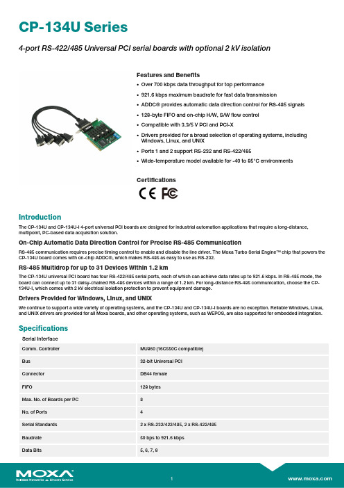
CP-134U Series4-port RS-422/485Universal PCI serial boards with optional2kV isolationFeatures and Benefits•Over700kbps data throughput for top performance•921.6kbps maximum baudrate for fast data transmission•ADDC®provides automatic data direction control for RS-485signals•128-byte FIFO and on-chip H/W,S/W flow control•Compatible with3.3/5V PCI and PCI-X•Drivers provided for a broad selection of operating systems,includingWindows,Linux,and UNIX•Ports1and2support RS-232and RS-422/485•Wide-temperature model available for-40to85°C environmentsCertificationsIntroductionThe CP-134U and CP-134U-I4-port universal PCI boards are designed for industrial automation applications that require a long-distance, multipoint,PC-based data acquisition solution.On-Chip Automatic Data Direction Control for Precise RS-485CommunicationRS-485communication requires precise timing control to enable and disable the line driver.The Moxa Turbo Serial Engine™chip that powers the CP-134U board comes with on-chip ADDC®,which makes RS-485as easy to use as RS-232.RS-485Multidrop for up to31Devices Within1.2kmThe CP-134U universal PCI board has four RS-422/485serial ports,each of which can achieve data rates up to921.6kbps.In RS-485mode,the board can connect up to31daisy-chained RS-485devices within a range of1.2km.For long-distance RS-485communication,choose the CP-134U-I,which comes with2kV electrical isolation protection to prevent equipment damage.Drivers Provided for Windows,Linux,and UNIXWe continue to support a wide variety of operating systems,and the CP-134U and CP-134U-I boards are no exception.Reliable Windows,Linux, and UNIX drivers are provided for all Moxa boards,and other operating systems,such as WEPOS,are also supported for embedded integration.SpecificationsSerial InterfaceComm.Controller MU860(16C550C compatible)Bus32-bit Universal PCIConnector DB44femaleFIFO128bytesMax.No.of Boards per PC8No.of Ports4Serial Standards2x RS-232/422/485,2x RS-422/485Baudrate50bps to921.6kbpsData Bits5,6,7,8Stop Bits1,1.5,2Parity None,Even,Odd,Space,MarkFlow Control None,RTS/CTS,XON/XOFFIsolation CP-134U-I Series:2kVSerial SignalsRS-232TxD,RxD,RTS,CTS,DTR,DSR,DCD,GNDRS-422Tx+,Tx-,Rx+,Rx-,RTS+,RTS-,CTS+,CTS-,GNDRS-485-4w Tx+,Tx-,Rx+,Rx-,GNDRS-485-2w Data+,Data-,GNDSerial Software FeaturesWindows Drivers DOS,Windows95/98/ME/NT/2000,Windows XP/2003/Vista/2008/7/8/8.1/10(x86/x64),Windows2008R2/2012/2012R2(x64),Windows Embedded CE5.0/6.0,Windows XPEmbeddedLinux Drivers Linux kernel2.4.x,Linux kernel2.6.x,Linux kernel3.x,Linux kernel4.x,Linux kernel5.x UNIX Drivers QNX6,SCO OpenServer,UnixWare7,Solaris10,FreeBSDPower ParametersInput Current CP-134U Series:180mA@5VDCCP-134U-I Series:850mA@5VDCPhysical CharacteristicsDimensions CP-134U Series:82.5x120mm(3.24x4.72in)CP-134U-I Series:115x120mm(4.52x4.72in)LED InterfaceLED Indicators Built-in Tx,Rx LEDs for each portEnvironmental LimitsOperating Temperature Standard Models:0to55°C(32to131°F)Wide Temp.Models:-40to85°C(-40to185°F)Storage Temperature(package included)-40to85°C(-40to185°F)Ambient Relative Humidity5to95%(non-condensing)Standards and CertificationsEMC EN55032/24EMI CISPR32,FCC Part15B Class BEMS IEC61000-4-2ESD:Contact:4kV;Air:8kVIEC61000-4-3RS:80MHz to1GHz:3V/mDeclarationGreen Product RoHS,CRoHS,WEEEMTBFTime480,209hrsStandards Telcordia SR332WarrantyWarranty Period5yearsDetails See /warrantyPackage ContentsDevice1x CP-134U Series serial boardCable1x M44to4x DB9-M cable,50cm(-DB9M models)1x M44to4x DB25-M cable,50cm(-DB25M models) Documentation1x document and software CD1x quick installation guide1x substance disclosure table1x warranty cardDimensionsCP-134U CP-134U-IOrdering InformationModel Name Serial Standards No.of Serial Ports Serial IsolationProtectionOperating Temp.Included CableCP-134U w/o Cable 2x RS-232/422/4852x RS-422/4854–0to55°C–CP-134U-T 2x RS-232/422/4852x RS-422/4854–-40to85°C–CP-134U-DB9M 2x RS-232/422/4852x RS-422/4854–0to55°C CBL-M44M9x4-50CP-134U-DB25M 2x RS-232/422/4852x RS-422/4854–0to55°C CBL-M44M25x4-50CP-134U-I w/o Cable 2x RS-232/422/4852x RS-422/48542kV0to55°C–CP-134U-I-T 2x RS-232/422/4852x RS-422/48542kV-40to85°C–CP-134U-I-DB9M 2x RS-232/422/4852x RS-422/48542kV0to55°C CBL-M44M9x4-50CP-134U-I-DB25M 2x RS-232/422/4852x RS-422/48542kV0to55°C CBL-M44M25x4-50Accessories(sold separately)Brackets1490000001000Bracket for DB44packCablesCBL-M44M25x4-50M44to4x DB25male serial cable,50cmCBL-M44M9x4-50DB44male to DB9male serial cable,50cm©Moxa Inc.All rights reserved.Updated Mar06,2020.This document and any portion thereof may not be reproduced or used in any manner whatsoever without the express written permission of Moxa Inc.Product specifications subject to change without notice.Visit our website for the most up-to-date product information.。
moxa安装指南
安装驱动程序如果是第一次安装或者想增加更多的多串口卡,请仔细阅读本节的内容。
由于windows 95/98操作系统支持即插即用功能,所以在这两种操作系统下,用户只需正确的安装industio cp-132系列多串口卡,win dows 95/98将会自动检测新安装的多串口卡硬件,第一次安装时系统会提示你安装驱动程序,此时你需要驱动程序的磁盘或光盘,以后安装时则不需要再提供驱动程序。
如果计算机系统有足够多的空闲i/o地址和中断号,一个计算机最多可以安装4块industio cp-132系列多串口卡。
以下流程框图说industio cp-32系列多串口卡的驱动程序安装步骤,每个阶段在相关章节都有详细介绍。
第一次安装驱动程序以下为第一次安装moxa c218turbo/pci智能多串口卡驱动程序的步骤。
在windows 95和windows 98两种操作系统下安装moxa c21 8turbo/pci智能多串口卡的驱动程序略有不同,以下分别介绍;左列为windows 95操作系统下的驱动程序安装步骤,右列为windows 9 8操作系统下的驱动程序安装步骤。
如果以前安装过moxa cp-132系列多串口卡,现在又在计算机主机中插入1片moxa cp-132系列多串口卡,操作系统将会立即进行到下一节所述的串口配置阶段,跳过以下这些步骤。
1.当检测到新的industio cp-132系列多串口卡,windows 95/98将会自动提示"new hardware found"消息框,然后显示如下对话框,单击[next]]按钮。
2.单击[other locations]按钮2.选择[displayalist...]选项,然后单击[next]]。
3. 在[location]输入区内键入“a:\windows.95”,然后单击[ok]按钮,操作系统自动读取指定位置上的文件。
4. 单击[finish]按钮。
- 1、下载文档前请自行甄别文档内容的完整性,平台不提供额外的编辑、内容补充、找答案等附加服务。
- 2、"仅部分预览"的文档,不可在线预览部分如存在完整性等问题,可反馈申请退款(可完整预览的文档不适用该条件!)。
- 3、如文档侵犯您的权益,请联系客服反馈,我们会尽快为您处理(人工客服工作时间:9:00-18:30)。
MOXA CP-134U板卡安装说明
1. MOXA CP-134U板卡的安装(Windows 2000)
1. 将MOXA CP-134U板卡插入主板的PCI扩展槽中,重新启动计算机。
Windows 2000 将自动检测新硬件,接着系统将弹出【欢迎使用找到新硬件向导】对话框。
2. 在弹出的【欢迎使用找到新硬件向导】对话框中,点击“下一步”继续。
3. 选择“搜索适于我的设备的驱动程序(推荐)”,点击“下一步”继续。
4. 选择“指定一个位置”,点击“下一步”继续。
5. 插入驱动光盘,引导至光盘驱动器\CP-134U\Software\Win2K-XP-2003 \MXSER,点击“确认”继续。
6. 点击“下一步”,将所需要的驱动文件复制到操作系统中。
7. 在接下来的【没有找到数字签名】对话框中,系统提示将要安装的软件不包括Microsoft 数字签名,点击“是”继续安装。
8. 等待系统复制所需要的文件。
9. 在【完成找到新硬件向导】界面中,系统提示你已经完成板卡驱动的安装过程,并且能够显示安装MOXA板卡的型号。
点击“完成”按钮,继续其余的安装过程。
10. 接下来的【发现新硬件】对话框,提示您系统正在为板卡的多个串口分别安装驱动。
11. 【发现新硬件】对话框消失后,就表示安装过程全部结束。
板卡及其扩展串口已经成功地安装了驱动程序。
打开【设备管理器】,可以看到新添加的多串口卡MOXA CP-134U,以及扩展出来的4个串口。
2. MOXA CP-134U板卡的设置
1. MOXA CP-134U板卡的物理模型,如图所示。
2. MOXA CP-134U板卡上面包含2组跳线器Jumper1~Jumper2,每组跳线器有30个针脚,分别对应扩展端口Port1和Port2。
用跳线覆盖右侧2列针脚,表示将扩展串口的类型设置为RS232;如果用跳线覆盖左侧2列针脚,表示将扩串口的类型设置为RS-422/485,详细设置将在后面介绍。
2. MOXA CP-134U板卡上面包含2组切换器S1~S2,每组切换器包含4个切换开关DIP1~DIP4。
通过设置这2组切换器和切换开关,可以将板卡的串口类型设置为:RS-422、4-wire RS-485或2-wire RS-485,具体的设置方法请参考下图。
3. 目前,在D3-Air-2.0播控系统中普遍使用RS-422类型的串口控制方式。
因此,在安装MOXA CP-134U板卡之前必须检查板卡设置是否正确。
首先将跳线Jumper1、Jumper2覆盖于左侧的2列针脚上面;然后,对切换器S1不作任何设置,将切换器S2的DIP1~DIP4 切
换到“OFF”。
此时,MOXA CP-134U板卡的4个扩展串口Port1~Port4 的类型全部设置为RS422。
4. MOXA CP-134U板卡串口类型设置为RS422,连接线缆接口的针脚定义请参考下图。
5. MOXA CP-134U板卡输出端口连接SW422倒换器输入端口控制线的线序(标准RS422控制线的线序),请参考下图。
6. SW422倒换器输出端口连接播出设备(标准RS422接口)控制线的线序,请参考下图。
7. SW422倒换器的后面板、连接线缆、Port1~Port4管脚的定义,请参考下图。
8. SW422倒换器Port1~Port4连接线缆的线序,请参考下表。
