APM-204C_208C MCPRO2使用手册
APM-204C_208C MCPRO2使用手册
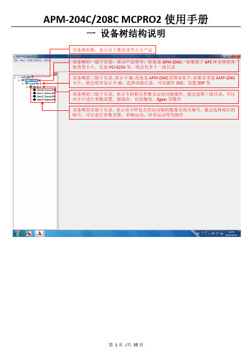
一 设备树结构说明二 设备树目录对应的菜单项及工具栏2.1 根目录及一级子目录(AMP ‐204C 子目录)2.1.1 对应菜单1、Initial Options 菜单项2、About 菜单项该菜单项用于获取MCPRO2版本信息、数据库版本信息及MCPRO2所支持的产品信息等等。
3、根目录右键菜单当选择ADLINK 根目录,右键点击,弹出保存/载入所有参数菜单,如下所示2.2 二级子目录(Card No 0子目录)2.2.1对应菜单及工具栏当选中相应的卡ID 目录(例如Card No 0),会弹出如下DIO 和DSP 操作菜单及工具栏2.2.2 右键菜单当选中相应的卡ID2.3 三级子目录(Motion 子目录)2.3.1对应工具栏2.3.2对应菜单栏2.3.3 右键菜单当选中相应卡ID 目录(例如Card No 0)下的Motion ,右击 会弹出如下右键菜单ServoOn 该卡下面的所有轴ServoOff 该卡下面的所有轴2.4 末级子目录(单轴操作子目录)2.4.1对应工具栏当选中相应的轴号时,会弹出如下工具栏2.4.2对应菜单栏2.4.3 右键菜单三 MCPRO2操作3.1 设置向导(SetupWizard )选择要操作的轴,在工具栏点击SetupWizard 按钮,弹出SetupWizard 对话框。
如下图示。
Step 1:Control Mode (控制模式)该步骤用于设置板卡控制模式及伺服更新率。
但是为防止客户误操作,控制模式设置和伺服更新率设置被移出该步骤。
如果要设置,请参考下面的设置。
1、选择要操作的轴2、点击SetupWizard按钮3、弹出SetupWizard对话框1、更改控制模式:注意:请根据每个轴使用的电机类型来设置每个轴的控制模式,控制模式一旦设定,请勿随意变更。
1、先选择Motion 子目录点击此按钮保存设置2、设置伺服更新率:以下两种方式都可以设置伺服更新率: 方式1:方式2:注意:如非必要,请勿随意更改伺服更新率。
莫克A E2200系列智能以太网远程I O说明书

ioLogik E2200SeriesSmart Ethernet remote I/O with Click&Go LogicFeatures and Benefits•Front-end intelligence with patented Click&Go control logic,up to24rules•Active communication with MX-AOPC UA Server•Saves time and wiring costs with peer-to-peer communications•Supports SNMP v1/v2c/v3•Friendly configuration via web browser•Simplifies I/O management with MXIO library for Windows or Linux•Wide operating temperature models available for-40to75°C(-40to167°F)environmentsCertificationsIntroductionMoxa’s ioLogik E2200Series Ethernet Remote I/O is a PC-based data acquisition and control device that uses proactive,event-based reporting to control I/O devices and features the Click&Go programming interface.Unlike traditional PLCs,which are passive and must poll for data,Moxa’s ioLogik E2200Series will,when paired with our MX-AOPC UA Server,communicate with SCADA systems using active messaging that is pushed to the server only when state changes or configured events occur.Additionally,the ioLogik E2200features SNMP for communications and control using an NMS(Network Management System),allowing IT professionals to configure the device to push I/O status reports according to configured specifications.This report-by-exception approach,which is new to PC-based monitoring,requires far less bandwidth than traditional polling methods.PC-Free Alarm and Control IntelligenceThis device supports simple yet powerful Click&Go™technology toconfigure event-driven reports and alarms delivered over email,TCP/UDP,or SNMP traps,giving you a powerful and effective tool fordelivering timestamped status updates in real time.With built-in Click&Go™intelligence,this device can be configuredfor simple outputs paired up with simple input triggers without theneed for a PC controller.This allows it to be configured toautomatically report I/O events according to conditions specified bythe user.SNMP for Ethernet Device ManagementBy using SNMP,IT engineers can configure the device to deliver alarms(traps)for specific I/O events,or use it to read or write directly to the I/O registers.For the strongest security,the device features SNMPv3,with authentication and encryption.With Moxa’s SNMP-capable I/O,even IT professionals can easily integrate industrial sensors and servos over an Ethernet backbone,and with its strong network management tools,it is ideal for a wide variety of industrial applications,including environmental monitoring,telecommunications,power production and delivery,and transportation.Push Technology for Events and AlarmsWhen used with MX-AOPC UA Server,devices can use active pushcommunications when communicating changes in state and/orevents to a SCADA system.Unlike a polling system,when using apush architecture for communications with a SCADA system,messages will only be delivered when changes in state or configuredevents occur,resulting in higher accuracy and lower amounts of datathat need to be transferred.SpecificationsControl LogicLanguage Click&GoInput/Output InterfaceAnalog Input Channels ioLogik E2240Series:8ioLogik E2242Series:4Analog Output Channels ioLogik E2240Series:2Buttons Reset buttonConfigurable DIO Channels(by software)ioLogik E2212Series:4ioLogik E2242Series:12Digital Input Channels ioLogik E2210Series:12ioLogik E2212Series:8ioLogik E2214Series:6Digital Output Channels ioLogik E2210/E2212Series:8ioLogik E2260/E2262Series:4 Isolation3k VDC or2k VrmsRelay Channels ioLogik E2214Series:6Rotary Switch0to9RTD Channels ioLogik E2260Series:6 Thermocouple Channels ioLogik E2262Series:8Digital InputsConnector Screw-fastened Euroblock terminal Counter Frequency900HzDigital Filtering Time Interval Software configurableDry Contact On:short to GNDOff:openI/O Mode DI or event counterPoints per COM ioLogik E2210Series:12channelsioLogik E2212/E2242Series:6channelsioLogik E2214Series:3channelsSensor Type ioLogik E2210Series:Dry Contact and Wet Contact(NPN)ioLogik E2212/E2214/E2242Series:Dry Contact and Wet Contact(NPN or PNP)Wet Contact(DI to GND)On:0to3VDCOff:10to30VDCDigital OutputsConnector Screw-fastened Euroblock terminalCurrent Rating200mA per channelI/O Mode DO or pulse outputI/O Type SinkOver-Current Protection0.65A per channel@25°COver-Temperature Shutdown175°C(min.)Over-Voltage Protection35VDCPulse Output Frequency1kHzDIO Output Leakage Current 4.0mA@24VDCRelaysConnector Screw-fastened Euroblock terminalContact Current Rating Inductive load:2A@30VDC,250VAC,110VACResistive load:5A@30VDC,250VAC,110VACContact Resistance100milli-ohms(max.)Electrical Endurance100,000operations@5A resistive loadMechanical Endurance1,000,000operationsMinimum Permitted Load1A@5VDCPulse Output Frequency0.3Hz at rated loadType Form A(N.O.)power relayI/O Mode Relay or pulse outputNote Ambient humidity must be non-condensing and remain between5and95%.The relaysmay malfunction when operating in high condensation environments below0°C. Analog InputsAccuracy ioLogik E2240/E2242:±0.1%FSR@25°C±0.3%FSR@-10to60°CioLogik E2240-T/E2242-T:±0.1%FSR@25°C±0.3%FSR@-10to60°C±0.5%FSR@-40to75°CBuilt-in Resistor for Current Input120ohmsConnector Screw-fastened Euroblock terminalI/O Mode Voltage/CurrentI/O Type DifferentialInput Impedance ioLogik E2240Series:900kilo-ohms(min.)ioLogik E2242Series:200kilo-ohms(min.)Input Range ioLogik E2240Series:±150mV,±500mV,±5V,±10V,0to20mA,4to20mAioLogik E2242Series:±150mV,0to150mV,±500mV,0to500mV,±5V,0to5V,±10V,0to10V,0to20mA,4to20mAResolution16bitsSampling Rate ioLogik E2240Series:All Channels:10samples/sec for voltage;6samples/sec for currentPer Channel:1.25samples/sec for voltage;0.75samples/sec for currentSingle channel:1.25samples/sec for voltage;0.75samples/sec for currentioLogik E2242Series:All channels:32samples/secPer channel:8samples/secSingle channel:100samples/secAnalog OutputsAccuracy ioLogik E2240:±0.1%FSR@25°C±0.3%FSR@-10to60°CioLogik E2240-T:±0.1%FSR@25°C±0.3%FSR@-10to60°C±0.5%FSR@-40to75°COutput Range0to10VDC4to20mAResolution12-bitRTDsAccuracy ioLogik E2260:±0.1%FSR@25°C±0.3%FSR@-10to60°CioLogik E2260-T:±0.1%FSR@25°C±0.3%FSR@-10to60°C±0.5%FSR@-40to75°CConnector Screw-fastened Euroblock terminalInput Connection2-or3-wireInput Impedance625kilo-ohms(min.)Sensor Type JPT100,JPT200,JPT500(-200to640°C)JPT1000(-200to350°C)NI100,NI200,NI500(-60to250°C)NI1000(-60to150°C)NI120(-80to260°C)PT1000(-200to350°C)PT50,PT100,PT200,PT500(-200to850°C)Resistance of310,620,1250,and2200ohmsResolution0.1°C or0.1ohmsSampling Rate All channels:12samples/secPer channel:2samples/secThermocouplesMillivolt Accuracy ioLogik E2262:±0.1%FSR@25°C±0.3%FSR@-10to60°CioLogik E2262-T:±0.1%FSR@25°C±0.3%FSR@-10to60°C±0.5%FSR@-40to75°CTC Accuracy Types J,T,E,S,B:±5°CTypes K,R,N:±8°CCJC Accuracy±0.5°C@25°C±1.5°C@-40to75°CConnector Screw-fastened Euroblock terminalInput Impedance1mega-ohms(min.)Millivolt Type±19.532mV±39.062mV±78.126mVFault and over-voltage protection:-35to+35VDC(power off);-25to+30VDC(poweron)Resolution16bitsSampling Rate All channels:12samples/secPer channel:1.5samples/secSensor Type J,K,T,E,R,S,B,NEthernet Interface10/100BaseT(X)Ports(RJ45connector)1Magnetic Isolation Protection 1.5kV(built-in)Ethernet Software FeaturesConfiguration Options Web Console(HTTP),Windows Utility(ioAdmin)Industrial Protocols CGI commands,Modbus TCP Server(Slave),Moxa AOPC(Active Tag),MXIO Library,SNMPv1Trap,SNMPv1/v2c/v3Management BOOTP,IPv4,SMTP,DHCP Client,HTTP,TCP/IPMIB Device Settings MIBTime Management SNTPLED InterfaceLED Indicators PWR,RDY,Serial,I/O StatusSerial InterfaceBaudrate1200bps to115,200kbpsConnector Terminal blockNo.of Ports1Parity NoneSerial Standards RS-485Stop Bits8Serial SignalsRS-485-2w Data+,Data-,GNDDIP Switch ConfigurationSerial Interface Fixed baudrateModbus TCPFunctions Supported1,2,3,4,5,6,15,16Mode ServerPower ParametersPower Connector Screw-fastened Euroblock terminalNo.of Power Inputs1Input Voltage12to36VDCPower Consumption ioLogik E2210Series:202mA@24VDCioLogik E2212Series:136mA@24VDCioLogik E2214Series:170mA@24VDCioLogik E2240Series:198mA@24VDCioLogik E2242Series:178mA@24VDCioLogik E2260Series:95mA@24VDCioLogik E2262Series:160mA@24VDC Physical CharacteristicsDimensions115x79x45.6mm(4.53x3.11x1.80in) Weight250g(0.55lb)Installation DIN-rail mounting,Wall mountingWiring I/O cable,16to26AWGPower cable,16to26AWGEnvironmental LimitsOperating Temperature Standard Models:-10to60°C(14to140°F)Wide Temp.Models:-40to75°C(-40to167°F) Storage Temperature(package included)-40to85°C(-40to185°F)Ambient Relative Humidity5to95%(non-condensing)Altitude2000m1Standards and CertificationsFreefall IEC60068-2-32EMC EN61000-6-2/-6-4Safety UL508EMI CISPR32,FCC Part15B Class AEMS IEC61000-4-2ESD:Contact:4kV;Air:8kVIEC61000-4-3RS:80MHz to1GHz:10V/mIEC61000-4-4EFT:Power:2kV;Signal:1kVIEC61000-4-5Surge:Power:1kVIEC61000-4-6CS:10VIEC61000-4-8PFMF1.Please contact Moxa if you require products guaranteed to function properly at higher altitudes.Shock IEC60068-2-27Vibration IEC60068-2-6DeclarationGreen Product RoHS,CRoHS,WEEEMTBFTime ioLogik E2210Series:213,673hrsioLogik E2212Series:217,722hrsioLogik E2214Series:307,329hrsioLogik E2240Series:155,941hrsioLogik E2242Series:204,391hrsioLogik E2260Series:327,282hrsioLogik E2262Series:341,063hrsStandards Telcordia SR332WarrantyWarranty Period ioLogik E2214Series:2years2ioLogik E2210/E2212/E2240/E2242/E2260/E2262Series:5yearsDetails See /warrantyPackage ContentsDevice1x ioLogik E2200Series remote I/ODocumentation1x quick installation guide1x warranty cardDimensionsOrdering InformationModel Name Input/Output Interface Digital Input Sensor Type Analog Input Range Operating Temp.ioLogik E221012x DI,8x DO Wet Contact(NPN),DryContact–-10to60°CioLogik E2210-T12x DI,8x DO Wet Contact(NPN),DryContact–-40to75°C2.Because of the limited lifetime of power relays,products that use this component are covered by a2-year warranty.ioLogik E22128x DI,4x DIO,8x DO Wet Contact(NPN or PNP),Dry Contact–-10to60°CioLogik E2212-T8x DI,4x DIO,8x DO Wet Contact(NPN or PNP),Dry Contact–-40to75°CioLogik E22146x DI,6x Relay Wet Contact(NPN or PNP),Dry Contact–-10to60°CioLogik E2214-T6x DI,6x Relay Wet Contact(NPN or PNP),Dry Contact–-40to75°CioLogik E22408x AI,2x AO–±150mV,±500mV,±5V,±10V,0-20mA,4-20mA-10to60°CioLogik E2240-T8x AI,2x AO–±150mV,±500mV,±5V,±10V,0-20mA,4-20mA-40to75°CioLogik E224212x DIO,4x AI Wet Contact(NPN or PNP),Dry Contact±150mV,0-150mV,±500mV,0-500mV,±5V,0-5V,±10V,0-10V,0-20mA,4-20mA-10to60°CioLogik E2242-T12x DIO,4x AI Wet Contact(NPN or PNP),Dry Contact±150mV,0-150mV,±500mV,0-500mV,±5V,0-5V,±10V,0-10V,0-20mA,4-20mA-40to75°CioLogik E22604x DO,6x RTD––-10to60°C ioLogik E2260-T4x DO,6x RTD––-40to75°C ioLogik E22624x DO,8x TC––-10to60°C ioLogik E2262-T4x DO,8x TC––-40to75°C Accessories(sold separately)SoftwareMX-AOPC UA Server OPC UA Server software for converting fieldbus to the OPC UA standardLCD ModulesLDP1602Snap-on module for the ioLogik E2200/R2100and ioMirror E3000Series©Moxa Inc.All rights reserved.Updated Nov12,2018.This document and any portion thereof may not be reproduced or used in any manner whatsoever without the express written permission of Moxa Inc.Product specifications subject to change without notice.Visit our website for the most up-to-date product information.。
PG0703P_C02A 等产品的编程手册说明书
目录1. 远程控制概述 (1)1.1 如何远程控制 (1)1.2 通信协议 (3)1.3 远程控制功能 (5)2. SCPI简介 (10)2.1 命令格式 (10)2.2 符号说明 (10)2.3 参数类型 (11)2.4 命令缩写 (12)3. 模式共用命令 (13)3.1 IEEE公用命令子系统 (13)3.2 系统命令 (15)3.3 存储命令 (20)3.4 显示控制 (21)3.5 模式命令 (22)3.6 扫描命令 (22)4. 频谱分析模式 (24)4.1 仪器模式命令 (24)4.2 Initiate命令子系统 (24)4.3 Sense命令子系统 (25)4.4 Calculate命令系统 (43)4.5 Measurement命令系统 (58)4.6 触发 (72)4.7 TG (73)4.8 调制解调 (75)5. 矢量网络分析模式 (77)5.1 频率控制 (77)5.2 幅度控制 (78)5.3 带宽控制 (80)5.4 扫描控制 (80)5.5 TG (81)5.6 迹线 (81)5.7 光标 (85)6. 故障定点分析模式 (98)6.1 频率控制 (98)6.2 幅度控制 (99)6.3 扫描控制 (100)6.4 迹线 (101)6.5 光标 (102)6.6 测量 (105)7. 调制分析模式 (110)7.1 频率控制 (110)7.2 幅度控制 (111)7.3 带宽控制 (112)7.4 扫描控制 (113)7.5 迹线 (114)7.6 光标 (117)7.7 测量 (119)7.8 触发 (124)8. 实时频谱分析模式 (126)8.1 频率控制 (126)8.2 幅度控制 (129)8.3 带宽控制 (131)8.4 扫描控制 (132)8.5 迹线 (134)8.6 光标 (137)8.7 触发 (139)8.8 测量 (142)9. EMI测量 (145)9.1 频率控制 (145)9.2 幅度控制 (147)9.3 带宽控制 (150)9.4 扫描控制 (151)9.5 迹线 (153)9.6 光标 (155)9.7 限制 (159)10. 编程示例 (168)10.1 使用VISA的编程示例 (168)10.2Sockets/Telnet示例 (182)SIGLENT 1. 远程控制概述分析仪支持通过USB、LAN、GPIB-USB接口与计算机进行通信。
O2K使用手册
背景校正:以背景样通量和氧浓度的线性相关性为基础,分为截距和斜率, 缺省值 a -2.00, b 0.025,一般情况下这两个值不用修改。在 slope uncorrected 模式下,背景校正不起作用。在进行传感器校正时,一般都是在 slope uncorrected 模式下。 通量推导因子(Flux derivation N):进行积分计算氧耗量所采取的点的个数, 可以设成 5-40. N 越小,时间分辨率越好,N 越大,氧耗量曲线越光滑。
三、参考检测样品浓度:
检测样品的最小单位
Sample
Concentration
心脏线粒体
0.01 mg protein cm−3
Volume 2.0 cm3
Temp. 30 oC
可透肌纤维 内皮细胞 T-淋巴细胞
1.5 mg wet weight cm−3 0.2 106 cells cm−3 1 106 cells cm−3
j=(Jt-J0)/(J1-J0)其中 Jt 是 t 时的流量,J0 为定义最小流量,J1 为选择 的最大流量,即将流量进行两点定标,最大流量为 1,最小流量为 0,这样 j(当前流量) 就处于 0-1 之间的值,根据 j 的大小来评价流量。
(4)Calcuate 现版软件中该功能未开放。 (5)Marks:标记 Statistics 标记状态统计 Names 标记名称管理,可通过模板修改 Manager Templates 管理模板 常用 Mark 名称: Routine: 正常的未破膜呼吸状态 Leak:加了寡霉素之后,线粒体呼吸抑制状态 ETS:解耦合后线粒体电子传递系统能力 ROX:ETS 抑制后剩余的氧消耗
Pocket Pro II 操作手册说明书

815.874.8001 • OPERATING INSTRUCTIONSPlease read this manual!This manual contains setup information necessary to achieve proper performance from your Pocket Pro II.(gray model# CEI-4710)(blue model# CEI-4700)1Table of ContentsBattery Installation . . . . . . . . . . . . . . . . . .2Automatic Shutdown . . . . . . . . . . . . . . . .2Forced Shutdown . . . . . . . . . . . . . . . . . . .2Quick Start! . . . . . . . . . . . . . . . . . . . . . . . . . .3Control Buttons . . . . . . . . . . . . . . . . . . . . .3Shot Detection . . . . . . . . . . . . . . . . . . . . . .4Shot Review Screen . . . . . . . . . . . . . . . . . .4Setting the PAR Time (second beep) . . .5Setting the Start Delay . . . . . . . . . . . . .5-6Display Backlighting . . . . . . . . . . . . . . . . .6Beeper Volume . . . . . . . . . . . . . . . . . . . . . .7Setting the Main Display Type . . . . . .7-8Shot Dead Time . . . . . . . . . . . . . . . . . . . . .9Shot Sensitivity . . . . . . . . . . . . . . . . . . . . . .9Setting the Date and Time . . . . . . . . . .10Battery Status . . . . . . . . . . . . . . . . . . . . . .11Resetting Factory Defaults . . . . . . . . . .11Timer “Wraparound” . . . . . . . . . . . . . . . .12Accuracy . . . . . . . . . . . . . . . . . . . . . . . . . . .12Specifications . . . . . . . . . . . . . . . . . . . . . .13Carrying Case . . . . . . . . . . . . . . . . . . . . . .13Limited Warranty . . . . . . . . . . . . . . . . . . .142Battery InstallationThe Pocket Pro II operates on a 9 volt alkaline battery . It is important to use alkaline batteries due to the power demand of the buzzer . To install the battery, remove the cover, connect the battery to the wire clip, fit the battery in the compartment, and replace the cover . Once installed, the Pocket Pro II will briefly display a sign-on message, followed by the main operating screen . The sign on message can be bypassed by pressing one of the menu buttons .If at any time you suspect the unit is not functioningnormally, try resetting it . The procedure is listed on page 11 of this manual .Automatic ShutdownIf no shots are detected and no buttons are pressed for a period of ten minutes, the timer will power down automatically . This will prevent battery discharge in the event it is not turned off after use . To wake up the timer, press the SET/ON button .Forced ShutdownTo turn the Pocket Pro II off, press and hold the MENU DOWN button for approximately 3 seconds .Quick Start!If you want to get started right away, all you have to do is press the start button on the side and shoot . The Pocket Pro II comes from the factory configured and ready to run . After the timer shuts down, press the SET/ON button to turn it on .Control ButtonsThere are four buttons on the front of the case . Looking at the front of the case,you will see the MENU UP/DOWN buttons on the left, and the SET UP/DOWN value buttons on the right .MENU UP/DOWNThe MENU UP/DOWN buttons are used tonavigate forward and backward through ashort loop of menu screens where the usercan access information and settable values .SET UP/DOWNIn menu screens with flashing settable values,pressing the SET (up arrow symbol) willincrease the value and SET/ON (down arrowsymbol) will decrease the value .MENUShot DetectionEach time a shot is detected, it will be added to the “shot string” maintained within the timer . The timer will automatically calculate the “split time .” Split time is the time between the current shot and the previous shot . The timer can store up to 99 shotsfor a given timing cycle . Subsequent shots will be stored by overwriting the previous value of shot 99 .Shot Review ScreenShots will be displayed on the shot review screenin a “one shot per line” format . Reading from leftto right in the shot line, the shot time appearsfirst, followed by the shot number, and finallythe split time, if any . When first navigating to theshot review screen after the start of a cycle, thefirst shot will appear on the 3rd line, and the lastshot will appear on the 2nd line, if there are 4 or more shots . Otherwise, the shots will be clearly identified by their shot numbers . Use the SET UP/DOWN buttons to scroll through the shot string .SPL 0.25SPL 0.35SPL 1.84SPL 0.844.00 # 54.35 # 61.84 #12.68#25Setting the PAR Time (second beep)The par time setting (also known as the “second beep”) comes configured from the factory for 0 seconds . When the par time is set to 0, the timer will beep only once, at the start of a timing cycle . Setting the par time to other than 0 will give you a beep at the start, and the end of the par time period . Par time is adjustable from 0 to 199 .9 seconds . Hold the SET UP or SET DOWN button to increase the speed at which the digits increment for large par times . Press the SET UP and SET DOWN buttons simulta-neously to reset the Par Time to zero .Setting the Start DelayThe start delay is completely configurable . If enabled, it can generate a fixed delay or random delays between .5 seconds and 9 .9 seconds . The timer is set to a factory default delay time between 1 and 4 seconds .Instant (No Delay)Using the MENU UP/DOWN buttons, advance to the “START DELAY TYPE” screen . Use the SET UP or SET DOWN button to select “ INSTANT .” The timer will start instantly when you press the start button .6Fixed DelayUsing the MENU UP/DOWN buttons, advance to the “START DELAY TYPE” screen . Use the SET UP or SET DOWN button to select “RANDOM”, then press the MENU UP button to advance to the “RANDOM START TIME – MINIMUM” and “RANDOM START TIME – MAXIMUM” display screens . In both screens, select the same delay time (between .5 seconds and 9 .9 seconds) . This will result in a fixed delay time at the setting specified . If you attempt to set a minimum time greater than the current maximum time, or a maximum time less than the current minimum time, the alternate time value will be “pushed” to match the setting currently being adjusted .Random DelayUsing the MENU UP/DOWN buttons, advance to the “START DELAY TYPE” screen . Use the SET UP or SET DOWN button to select “RANDOM” . Then press the MENU UP button to advance to the “RANDOM START TIME – MINIMUM” and “RANDOM START TIME – MAXIMUM” display screens . For each screen, select the desired minimum and maximum delay time to create a start delay “window” of time .Display BacklightingUse the SET UP/DOWN buttons to set the number of seconds (from 0 to 99) the display backlighting will remain on . Setting the value to zero will turn it off . To activate the backlight, press any button . If you would like to illuminate the current display, press the MENU UP , then MENU DOWN button . Longer periods with the7backlight turned on will shorten battery life .Beeper VolumeThe beeper volume can be adjusted by pressing the SET UP or SET DOWN button . Changes are indicated by a “bar graph” display indicator as well as a sample of the sound level . A new setting will be saved automatically .Setting the Main Display TypeThe Pocket Pro II can be configured to show three different types of main displays . These are selected from the “MAIN SCREEN TYPE” menu, and are described below .Review DirectWhen the “Review Direct” main display is selected, the last split time will appear in the upper right hand corner of the main display . Pressing either the SET UP or SET DOWN button will jump directly to the shot review screen . Pressing the MENU UP button will return to the main display screen .8“RPM” ModeWhen the “Rounds per Minute” main display isselected, the Pocket Pro II no longer displays shot times, but now will display rounds per minute . To use this mode, press the START button . After the beep, fire shots; the timer will display the rounds per minute based on the number of shots and the time between the first shot and the last . Shotsrecorded more than 199 .99 seconds after the start beep will render readings invalid until START is pressed again . The normal shot dead time setting is overridden when in RPM mode and set to a fixed value of 0 .032 seconds . This allows the Pocket Pro II to detect shots at rates of up to 1800 RPM . (NOTE: Please see Accuracy on page 12)Single Time OnlyWhen the “Single Time Only” main display isselected, the current shot time appears on the main display and is sized to fill up the screen . Pressing either the SET UP or SET DOWN button will jump directly to the shot review screen . Pressing the MENU UP will return to the main display screen .9Shot Dead TimeThe SHOT DEAD TIME feature is used to reduce false shot recordings due to echoes or ringing . Once a shot is detected, the Pocket Pro II will disregard subsequent shots for a short period of time . The default setting is .11 seconds, but can be adjusted from .05 to .12 seconds . If your split time between shots is less than .11 seconds, an adjust-ment will be necessary . Navigate to the SHOT DEAD TIME display using the MENU UP/DOWN buttons and adjust as needed . The shot dead time setting is set to a fixed value of .032 seconds when in the RPM mode .Shot SensitivityShot sensitivity is variable between 0 and 25 and is settable from the SHOT SENSITIV-ITY screen . Use the SET UP/DOWN buttons to adjust the value . Increase the value for greater sensitivity; decrease it for less sensitivity . Keep in mind that higher sensitivity settings will also increase the chance of false shot detection from handling, vibration, or other noise sources .10Setting the Date and TimeUsing the MENU UP/DOWN buttons, cycle through the MONTH, DAY, YEAR, HOURS, and MINUTES display screens using the SET UP/DOWN buttons to set the date and time . To synchronize to the nearest second, set the “MINUTES” value and at the mark, advance to the next/previous display screen . Internally, the timer will be set to 0 seconds at the instant you change to a different menu screen . Be sure to note the AM/PM setting on the hours screen . The timer will usually retain time and date settings when changing batteries if the change is done as quickly as possible . However, if the battery is removed and not replaced immediately, time/date information is lost and must be reset .11Battery StatusBattery Status can be monitored in two places . On the main screen, a battery icon appears in the lower right-hand corner of the display . As the battery discharges, the icon will become more and more “hollow .” For a more detailed display of the battery condition, press the MENU UP or DOWN buttons repeatedly until the “battery condition” display appears . Here, you can see an expanded “bar graph” type display of the battery level . The timer will operate normally down to a reading of around 6V . When the battery becomes depleted to approximately 6 .5 volts, the display backlighting will be turned off to conserve power . This will allow the session to continue in the event a replacement battery is not readily available . When the battery voltage becomes depleted to less than 6 volts, the Pocket Pro II will shut down to avoid undefined operation .Resetting the Timer to Factory DefaultsTo reset factory default values within your timer, remove the battery, then hold down the “Start” button and reinstall the battery . Look at the display to see the message “INIT N/V MEMORY” . Now release the start button and the reset is complete .ICON12Timer “Wraparound”Internally, the timer is continuously counting up to 199 .99 seconds and then “wrapping around” to 0 . When the start button is pressed, this internal time is reset to 0 . This means that the maximum timing period is limited to 199 .9 seconds . Shots recorded after this will reflect the “wrapped” time . Splits are calculated correctly, as long as the timer has wrapped around only once since the start of the cycle .AccuracyThe Pocket Pro II measures internally to a resolution of 1 mSec, but shot displays, splits, etc . are internally rounded to the nearest 10 mSec . For this reason, RPM readings may appear to be inaccurate when manually calculated using the displayed shot string values . In reality, the RPM reading is actually more accurate than the manual calculation since it is calculated using the internal shot times, which are measured with 1mSec resolution .13Specifications• Operating temp range: 32-110 deg . F .• Accuracy: Quartz crystal controlled . (Within 1/100 second)• Max # of shots stored:99• Max rounds per minute: 1800• Battery type: 9 volt alkalinePocket Pro II Carrying Case• This handy case will protect your timer during transport and storage .• It features a zipper storage compartment for spare batteries, velcro belt strap, and a Competition Electronics embroidered logo .To Order Call 815-874-8001 or visit our website at(model# CEI-4707)14Limited Warranty* * * * * * * * * * * * * * * * * * * * * * * * * * * * * * * * * * * * * * * * * * * * * * * * * * * * *COMPETITION ELECTRONICS, INC., warrants the Pocket Pro II manufactured by it to be free from defects in material and work-manship for a period of 2 years from date of purchase by the original purchaser for use. COMPETITION ELECTRONICS, INC., at its option, will repair or replace without charge, or refund the purchase price of, any product which fails during the warranty period by reason of a defect in material or workmanship found upon examination by COMPETITION ELECTRONICS, INC., to have been the cause of the failure. This warranty does not cover any failures attributable to abuse, mishandling, and failure to follow operating instructions, alteration or accident.To make claim under this warranty, the purchaser must return the product to COMPETITION ELECTRONICS, INC., at the address shown below, properly packed and with shipping charges prepaid. All claims must be made within (30) days after the product failure and, in any event, within thirty (30) days after the expiration of the 2-year warranty. All claims must be accompanied by a sales slip or other written proof of date of purchase.TO THE EXTENT PERMITTED BY LAW, ANY AND ALL IMPLIED WARRANTIES, INCLUDING MERCHANTABILITY AND FITNESS FOR PARTICULAR PURPOSE, ARE EXCLUDED; ANY IMPLIED WARRANTIES NOT EXCLUDED ARE LIMITED IN DURATION TO 2 YEARS FROM DATE OF PURCHASE. INCIDENTAL AND CONSEQUENTIAL DAMAGES ARE EXPRESSLY EXCLUDED FROM THE REMEDIES AVAILABLE TO THE PURCHASER, AND THE REMEDIES PROVIDED IN THIS WARRANTY SHALL BE EXCLUSIVE TO THE EXTENT PERMITTED BY LAW.(Note: Some states do not allow limitations on how long an implied warranty lasts or the exclusion or limitation of incidental or conse-quential damages, so the foregoing limitations and exclusions may not apply to you. This warranty gives you specific legal rights, and you may also have other rights which vary from state to state.)If any product returned by the purchaser is found by COMPETITION ELECTRONICS, INC., to require service not covered by warranty, COMPETITION ELECTRONICS, INC., will so advise the purchaser and request further instructions. COMPETITION ELECTRONICS, INC., will recondition to working order any Pocket Pro II returned to it regardless of condition upon the purchaser’s remittance of payment of 1/2 of current retail price, if it is still manufactured by COMPETITION ELECTRONICS, INC.* * * * * * * * * * * * * * * * * * * * * * * * * * * * * * * * * * * * * * * * * * * * * * * * * * * * *Return Shipping Address:Competition Electronics, Inc . 3469 Precision Dr . Rockford, IL 61109Contact Us:Phone: 815-874-8001 FAX: 815-874-8181 Rev 8-2019User Manual / Operating Instructions。
AMP-204C培训资料

IVM – 最大速度中断 IACC – 加速度中断 IDEC – 减速度中断 IMDN – 运动完成中断 IASTP – 异常停止中断 ISPEL – 软正限位中断 ISMEL – 软负限位中断
• • • • 基于PCI总线 基于 TI的DSP开发,处理器频率高达375 MHz 2M(32位)板载内存,用于程序及数据 最大支持4/8轴(对于AMP-204C/208C )
• 编码器输入频率高达20MHz(4xAB),输入模式支持OUT/DIR ,CW/CCW,1xAB,2xAB,4xAB • 单独支持机械开关信号:± EL,ORG,EMG • 支持增量式编码器 • 支持伺服电机IO接口:INP/ZSP,ALM,ALM_RST,SVON
• 额外提供20路DI/DO(对于AMP-204C)或24路 DI/DO(对于AMP-208C) • 拨码开关设置卡ID
5
运动&控制功能概述
6
运动&控制功能概述
• 支持速度曲线规划(T型和S型) • 支持多种运动模式
– – – – – – – – – 点到点运动 速度运动 寸动 回零运动 插补运动 单轴和多轴连续运动 2轴点表运动(支持速度规划) 同步运动 龙门架构
注意:不支持跨卡片插补
单轴和多轴连续运动
• 支持单轴和多轴插补混合连续运动 • 运动队列缓冲区长度为10,支持实时添加运动指令 到运动 队列
运动队列 活动缓冲区
Axis #0 10 Axis #1 10 Axis #7 10
华科仪HK-208型磷酸根分析仪使用说明书v10

京制 01080126 号HK-208型磷酸根分析仪使用说明书产品版本: 1.0北京华科仪电力仪表研究所目 录一、概述1.1 仪器简介 (1)1.2 显示及操作面板 (1)1.3 工作原理 (2)二、技术指标 (3)三、试剂的制备3.1 显色试剂的制备 (5)3.2 标准储备溶液 (5)四、编程4.1 开机 (6)4.2 程序单元 (6)4.2.1 主菜单 (6)4.2.2 空白校准菜单 (7)4.2.3 曲线校准菜单 (8)4.2.4 参数设置菜单 (9)4.2.5 历史数据菜单 (10)五、仪器的使用5.1 使用条件 (12)5.2 安装方法 (12)5.3 仪器的校准 (12)5.3.1 曲线校准 (12)5.3.2 空白校准 (15)5.4 水样的测定方法 (15)5.4.1 待测水样的显色 (15)5.4.2 水样的测量 (15)5.5 注意事项 (15)六、仪器的成套性 (16)附录一:仪表使用注意事项 (17)附录二:曲线校准结果的合理性判定 (18)附录三:更换升级芯片的方法 (19)联系我们 (20)一 概述1.1仪器简介仪器外型为一个密封的壳体,坚固防水;显示屏为大屏幕的点阵液晶,中文菜单,易于理解,操作方便;测量数据为直读式,并可根据需要保存测量值。
1.2显示及操作面板其中,键盘功能如下::垂直或水平循环移动光标,选择所需的菜单或参数。
:当参数选定后,可增加参数的数值;当显示历史数据、对历史数据进行查询时,按此键可显示上页数据。
:当参数选定后,可减小参数的数值。
当显示历史数据、对历史数据进行查询时,按此键可显示下页数据。
:当选定所需的菜单或功能项,按此键可进入该菜单或功能项; :返回上一菜单或上一页。
:排空比色池中的液体,此时测量值不存储。
排液时间为16秒。
:对测量数值进行存储,同时排空比色池中的液体。
1. 测量数值的存储:仪器具有6个存储通道,可将不同水样的测量值存储到所需的通道中。
APM2 APM2 中文快速入门指南- 第一篇硬件和常用软件-rev1
APM2 中文快速入门指南-第一篇硬件和常用软件ArduPilotMega(APM)是市面上最强大的基于惯性导航的开源自驾仪(并且是最便宜的之一!)特性包括:∙免费开源固件,支持飞机(“ArduPlane”),多旋翼(四旋翼,六旋翼,八旋翼,十旋翼等),直升机(“ArduCopter”)和地面车辆(“ArduRover”)!∙通过点击式程序简化设置和固件上传。
无需编程∙通过点击式的桌面程序完整支持任务脚本规划∙可以支持上百个三维航点∙使用强大的MAVLink协议,支持双向遥测站和飞行中任务设置∙多种免费地面站,包括APM PLANNER ,HK HCS,∙跨平台,支持在Windows,Mac,甚至手机安卓系统,和Linux。
在Windows下使用图形任务规划设定工具(苹果下可用模拟器)。
Arduino的编程环境,也是完全跨平台的。
∙自动起飞,降落和特殊动作命令,例如视频和照相控制∙完整支持Xplane和Flight Gear 半硬件仿真∙包括继电器,可以根据任务脚本控制触发任何设备,∙硬件包括:o三轴陀螺仪o三轴加速度计o输出数字化6轴或9轴融合数据,包括旋转矩阵、四元数、欧拉角和原始数据格式o三轴角速度传感器(陀螺仪),感度高至131 LSBs/dps量程±250, ±500, ±1000, 和±2000dpso三轴加速度计,可编程量程±2g, ±4g, ±8g 和±16go测量高度的空气压力传感器o10Hz的GPS模块o监视电池状态的电压传感器o16MB板上数据记录存储器,日后会支持TF卡扩展。
任务数据自动记录,并可以导出为KML的格式o三轴磁力计o(可选)空速传感器o(可选)电流传感器APM对于玩家的要求较深的航模知识玩飞控的想法符合实际有一定的电子基础略懂英文及编程APM1和APM2的差别APM1和APM2之间的主要差别在传感器。
Kramer RC-208 快速上手指南说明书
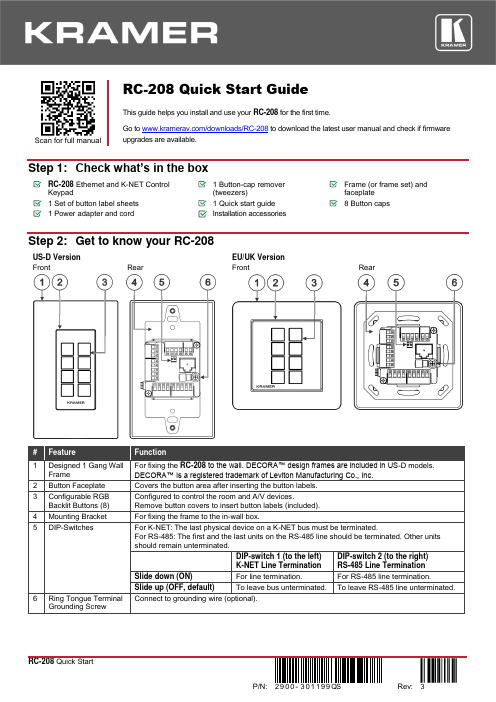
Scan for full manualRC-208 Quick Start GuideThis guide helps you install and use yourRC-208 for the first time.Go to /downloads/RC-208to download the latest user manual and check if firmwareupgrades are available.Step 1: Check what’s in the boxRC-208 Ethernet and K-NET Control Keypad1 Button-cap remover(tweezers)Frame (or frame set) and faceplate 1 Set of button label sheets 1 Quick start guide 8 Button caps 1 Power adapter and cordInstallation accessoriesStep 2: Get to know your RC-208US-D Version EU/UK Version FrontRearFrontRearStep 3: Configure RC-208To configure RC-208 buttons via K-Config:• Configure RC-208 (go to /product/RC-208).• Connect RC-208 to a PC via the Ethernet or connect via the mini USB port. •Sync the configuration to RC-208.To insert a button label for the first time:1. Cut out the appropriate button label from the buttonlabel sheets and place a label inside the button cover. 2. Cover with the button cap.To replace a label:1. Using the supplied tweezers, grip the button via theHorizontal or vertical ledges and remove the button cap. 2. Replace the label and cover the button with the buttoncap.You do not have to detach the faceplate to remove a button.Step 4: Connect the inputs and outputsAlways switch OFF the power on each device before connecting it to your RC-208. For best results, we recommend that you always use Kramer high-performance cables to connect AV equipment to RC-208.Step 5: Install RC-208After connecting the ports, insert the device into the in-wall box and connect the parts as shown in the illustrations below:EU/UK VersionUS-D VersionWe recommend that you use any of the following standard 1 Gang in-wall junction boxes (or their equivalent): •US-D: 1 Gang US electrical junction boxes.•EU: 1 Gang in-wall junction box, with a cut-hole diameter of 68mm and depth that can fit in both the device and the connected cables (DIN 49073).•UK: 1 Gang in-wall junction box, 75x75mm (W, H), and depth that can fit in both the device and the connected cables (BS 4662 or BS EN 60670-1 used with supplied spacers and screws).Step 6: Connect the powerConnect the 12V DC power adapter to the RC-208 and plug the adapter into the mains.Safety InstructionsCaution: There are no operator serviceable parts inside the unit.Warning: Disconnect the power and unplug the unit from the wall before installing.See for updated safety information.Step 7: Operate RC-208Operate RC-208 via the front panel buttons, as a room controller keypad configured via K-Config.。
vLocPro2系列管线仪操作手册

2 标准接收机...................................................................................................................................................... 8
2.4 定位模式 .................................................................................................................................. 14 2.4.1 接收线圈与定位信号 ......................................................................................................... 14 2.4.2 峰值定位模式.................................................................................................................... 15 2.4.3 峰值箭头定位模式............................................................................................................. 17 2.4.4 宽峰定位模式.................................................................................................................... 18 2.4.5 谷值定位模式.................................................................................................................... 19 2.4.6 示踪探头模式.................................................................................................................... 20
APM中文使用手册Word版
一、介绍ArduPilotMega 自动驾驶仪(简称APM 自驾仪)是一款非常优秀而且完全开源的自动驾驶控制器,可应用于固定翼、直升机、多旋翼、地面车辆等,同时还可以搭配多款功能强大的地面控制站使用。
地面站中可以在线升级固件、调参,使用一套全双工的无线数据传输系统在地面站与自驾仪之间建立起一条数据链,即可组成一套无人机自动控制系统,非常适合个人组建自己的无人机驾驶系统。
二、性能特点•免费的开源程序,支持多种载机。
ArduPlane 模式支持固定翼飞机,Arducoper 模式支持直升机与多旋翼(包括三轴、四轴、六轴、八轴等),ArduRover 模式支持地面车辆;•人性化的图形地面站控制软件,通过一根Micro_USB 线或者一套无线数传连接,鼠标点击操作就可以进行设置和下载程序到控制板的MCU 中,无需编程知识和下载线等其它硬件设备。
但如果你想更深入的了解APM 的代码的话,你仍旧可以使用Arduino 来手动编程下载;•地面站的任务规划器支持上百个三维航点的自主飞行设置,并且只需要通过鼠标在地图上点击操作就行;•基于强大的MAVLink 协议,支持双向遥测和实时传输命令;•多种免费地面站可选,包括Mission Planner ,HK GCS 等,还可以使用手机上的地面站软件,地面站中可实现任务规划,空中参数调整,视频显示,语音合成和查看飞行记录等;•可实现自动起飞,自动降落,航点航线飞行,自动返航等多种自驾仪性能;•完整支持Xplane 和Flight Gear 半硬件仿真三、硬件构成o核心MCU采用ATMEL的8bit ATMEGA2560o 整合三轴陀螺仪与三轴加速度的六轴MEMS传感器MPU6000 o 高度测量采用高精度数字空气压力传感器MS-5611o 板载16MB的AT45DB161D存储器o 三轴磁力计HMC5883o8路PWM控制输入o 11路模拟传感器输入o 11路PWM输出(8路电调电机+3路云台增稳)o GPS 模块可选MTK 3329及支持ublox输出的NEO-6M、7M、LEA-6H等o 可屏蔽板载PPM解码功能,外接PPM解码板或者外接PPM接收机o 可屏蔽板载罗盘通过I2C接口使用外置扩展罗盘o (可选)OSD模块,将无人机姿态、模式、速度、位置等重要数据叠加到图像上实时回传o (可选)空速传感器o (可选)电流电压传感器o (可选)超声波测距传感器o (可选)光流定点传感器o(可扩展)其它UART、I2C、SPI 设备四、硬件方框图五、飞控板概览正面图1、数传接口2、模拟传感器接口3、增稳云台输出接口4、ATMEGA2560 SPI 在线编程接口(可用于光流传感器)5、USB 接口6、遥控输入7、功能选择跳线8、GPS 接口9、I2C 外接罗盘接口10、ATMEGA32U2 SPI 在线编程接口11、多功能可配置MUX 接口(默认为OSD 输出)12、电流电压接口13、电调供电选择跳线14、电调输出接口背面图1、SPI 的MISO 电压选择2、PPM 输入选择3、MUX 接口功能选择六、硬件安装在APM 主板拿到手后,首先应明确自己的用途,并且熟悉了上述功能和接口再进行后续的硬件安装和连接。
AMP-204C龙门设置方法

MP-204C龙门模式设置方法一、龙门的特点 (2)二、龙门轴参数说明 (3)三、MCPRO2设定及操作方法 (3)四、相关函数说明 (7)AMP-204C龙门模式设置方法一、龙门的特点龙门模式是依照双驱的龙门机构设定,所以有以下特点:1、除了使用者手动解除齿轮关系外,齿轮关系将不会被解除;2、若从轴的EMG/ALM/PEL/MEL/ALM信号为ON时,主从轴的运动将会停止;3、当从轴收到stop(),emg_stop(),servo_off()时,主从轴的运动将会停止;4、不允许变更齿轮比,固定比例为1:1;5、接合速率的设定将被忽略。
另外,此模式下,有两层位置误差的保护机制,控制器在每个运动周期,检查两轴反馈的位置误差是否超过误差设定,若超过第一层(Level 1)位置误差设定值时,进行减速停止;若超过第二层(Level 2)位置误差设定值时,会对两轴进行Servo-Off动作。
其操作方式是对从轴的轴参数进行设定1:选定跟随的主轴,2:两阶段的位置误差保护。
设定完后,使用APS_start_gear(从轴ID)来启动龙门模式。
当模式启动后,只需操作主轴即可,从轴的动作会和主轴完全一致。
二、龙门轴参数说明三、MCPRO2设定及操作方法打开MCPRO2调试软件后,进行如下两步操作第二步第一步然后会弹出如下提示对话框选择OK后,会出现如下界面选择相应的Mode,下方会出现相应模式的原理图,如选择Gentry模式后,原理图如下:此时,在下方的方框内,对需要设定为龙门的轴进行参数设定,例如下图,将轴1设定为跟随轴,轴0为主轴,则设置方法为:1、将轴1设定为Gantry模式,并在轴1的主轴列表内,选择轴1的跟随源(以轴0的脉冲为参考),如下图:2、设定轴1的两层保护数值,如下图:3、设定完成后,点击按钮保存参数设定;4、将Set按钮后的Enable框勾选,此为打开轴1的龙门模式,如下图:设置完成后,显示如下:至此,龙门模式设定完成,其中轴0为主轴,轴1为从轴。
icom IC-208H中文说明书
译者自述因为购买了IC-208H,所有有时间细看了一遍英文说明书。
这对于了解这部电台的特性和使用方法,充分开发它的用途是很有必要的。
因此花了一些时间把它翻译成中文,并送给所有拥有这款电台或对业余电台感兴趣的朋友们。
为了便于大家阅读,我完全按照原文的格式编译这本说明书,包括页码、插图都与原文相同。
同时,也请各位朋友对照原文阅读,帮助找出译文中的错误。
在译文中,我用“按”,“按一下”“按动”等词表示快速触按相应的按键,用“按住”表示要按一秒钟。
请大家在操作的时候注意这个区别。
BG1DOT对我翻译这本说明书给予了大力支持,并提供服务器空间存放这本手册供大家下载。
在此表示感谢!希望有机会与各位朋友通联,交流参加业余电台活动的经验和感受!VERY 73! BG1FJP配套附件目录1..面板描述……………………………1-10前面板—控制器 (1)功能显示 (3)后面板 (5)手咪(HM-133) (7)手咪键盘 (8)备选手咪 (10)2. 设置一个频率……….……………11-14准备 (11)使用调谐旋钮 (12)使用【▲】【▼】键 (12)使用键盘 (12)直流电缆线(3米)..........................1 调谐步长设置.. (13)车载安装支架...............................1 锁止功能.. (14)手咪(HM-133)................................1 3. 基本操作................................15-18 保险管(20A)..................................1 接收. (15)安装螺丝,螺母,垫圈......................1套监听功能.. (15)手咪挂钩.....................................1 静躁衰减器 (16)面板分离电缆(3.5米)....................1 发射. (17)选择输出功率 (17)单触PTT功能...............................18 扫描恢复条件.. (45)静音功能.....................................18 8.优先监听.................................46-47 4.中继设置...............................19-25 优先监听类型.. (46)概述...........................................19 优先监听操作.. (47)配置中继....................................20 9.DTMF存储编码..........................48-51 亚音...........................................22 编制一个DTMF码. (48)差频...........................................24 传送一个DTMF码. (50)自动中继(仅限美国版本)................25 DTMF速率.. (51)5.存储设置...............................26-37 10.寻呼及音频静躁......................52-55 概述...........................................26 寻呼操作.. (52)选择存储信道...............................26 音频/数字音频静躁操作. (54)编制存储信道...............................27 静躁频率扫描.. (55)复制存储内容..............................29 11.其他功能...............................56-74 编制信道名称...............................31 设置模式.. (56)清除存储.....................................34 初始设置模式.. (61)选择存储编组...............................35 AM/FM窄带模式 (65)设置存储编组..............................36 天气预报操作(仅限美国版本).. (66)传输编组内容..............................37 手咪键.. (67)6.呼叫信道设置........................38-39 局部重置.. (68)选择呼叫信道..............................38 全部重置.. (68)传输呼叫信道..............................38 克隆数据.. (69)编制呼叫信道..............................39 数据通信.. (71)7.扫描操作.............................40-45 12.维护................................... 75-76 扫描类型........................... .......40 故障分析.. (75)扫描开始/停止..............................41 更换保险管.. (76)编制扫描边界................................42 13.性能指标及附件......................77-78 设置跳跃扫描................................44 性能指标.. (77)1 面板描述▉前面板—控制器①[SET•LOCK]④[PWR]电源开关按一下进入设置模式(P56)按住一秒钟即可开启或关闭电源按住一秒打开或关闭锁止功能(P14)⑤手咪连接器②[DIAL]调频旋钮在设置模式下进行功能设置,调节扫描的方向(P41)③[VOL]音量旋钮扬声器音量调节(P15)--第1页共77页--面板描述 1⑥[SQL]静噪控制旋钮12.[BAND]键调节收信时的静躁深度(P15)按下即可选择频段(P11)顺时针方向旋转到中间位置时,收信衰减器当工作于呼叫频道时,按下可选开启(屏幕右上角出现ATT),最大可衰减20dB 择呼叫1或呼叫2(P38)⑦[MONI•DTMF]键按住一秒钟,可选择操作模式(P65)按一下,开启或关闭监听功能(P15)13.[S.MW•MW]存储通道编程或删除按住一秒钟,开启或关闭DTMF编码存储功能(P48)(P27,39,42)⑧[LOW•DUP]键功率调节及差频设置按下可选择一个存储通道每按一下调节发射功率低、中、高(P17)按住一秒钟可对所选择的通道编程按住一秒钟,设置差频:下差(DUP-)、上差(DUP+) 14.面板安装锁定栓或同频收发(P20)⑨[TONE•T-SCAN]亚音频及亚音频扫描功能设置按住一秒钟,开始亚音扫描(P55)⑩[M/CALL•PRIO]每按一下,选择存储信道、呼叫信道、天气预报通道(仅限美国版)(P11,26,38,66)按住一秒钟,调用优先监听(P47)11[V/MHz•SCAN]按一下可以选择VFO模式并改变频率兆位(P11)按住一秒钟,进入频率扫描,再按一下即可停止扫描(P41)--第2页共77页--1 面板描述▉功能显示①发射指示③亚音指示发射时显示 TX(P17) 发射亚音被设置时,显示T (P20)当使用单触PTT功能发射时,TX闪烁(P18)收发亚音都被设置时,显示 T SQL(P52)②差频指示数字亚音被设置后,显示DTCS (P52)上差时显示 DUP 寻呼功能被启用后,((•))与 T SQL或DTCS下差时显示 DUP- 一起显示(P52)--第3页共77页--面板描述 1④窄带模式显示 12.存储信道号码显示此模式仅用于美国版本•显示选定的存储信道号码(P26)⑤调幅模式(P65)•显示选定的编组信息(P35)⑥接收衰减显示(P16)•呼叫信道被选定时,符号“C”出现(P38)在初始设置中可以将接受衰减器关闭(P63)•锁止功能被选定时,符号“L”出现(P14)⑦自动关机显示(P62) 13.跳跃指示(P44)设置了自动关机功能后,该符号就会显示¶当所显示的存储信道被定义为跳跃信道时,⑧静音显示(P18)出现此符号设置了静音后,此符号就会显示¶当所显示的频率顶设制为跳跃频率时,出现只有用手咪才能设置静音 P 跳跃:扫描时跳过此信道或频率⑨频率显示 14.存储显示(P11,26)显示操作频率、频道名称、设置模式的内容等当选择了存储模式时出现此符号当进行扫描时,频率的小数点会闪烁(P41)15.S/RF指示器当使用DTMF存储功能时,第一位显示为“d”(P48) ¶收信时显示信号强度(P15)⑩天气预报显示此功能仅限美国版本¶发射时显示发射功率(P17)11.优先监听显示(P47) 16.发射功率指示启动优先监听时此符号出现低功率时,显示“LOW”暂停优先监听时此符号闪烁中功率时,显示“MID”大功率时,无显示17.状态指示¶接收到一个信号或静躁打开时,显示“BUSY”¶监听开启时,“BUSY”闪烁(P15)--第4页共77页----第5页共77页--1 面板描述▉背面板 ④天线连接口[ANT ]连接一根用50Ω同轴电缆,PL-259连接头连接的50Ω天线。
OMP# 4202 – 10 00 迪伦压力开关操作手册说明书
164/26/06 ‘SS-2” PRESSURE SWITCH OPERATION MANUAL OMP# 4202 – 10/00The pressure switch “BLOCK AND BLEED” action is the same when the instrument pressure is connected to the “LO IN” port and the “HI IN” port is left unused. For this mode of operation, the switch acts as normally closed valve and is called a low switch. When normal sense pressure is acting on the piston, the center O-ring on the spool is between the “HI IN” port and the “OUT” port, thus preventing the instrument pressure from passing to the “HI PORT” of the switch body, but allowing it to flow from the “LO IN” port to the “OUT” port of the switch body. When the sense pressure decreases to an abnormal level, the spring force shifts the spool and the middle O-ring on the spool becomes positioned between the “LO IN” port and “OUT” port. Pressure at the “LO IN” port is “BLOCKED” from entering the “OUT” port and pressure at the “OUT” port “BLEEDS” to atmosphere from the “HI IN” port.The Ruelco “SS-2” pneumatic pressureswitch is a three way block and bleedvalve that is operated by pressure actingon a piston opposing and adjustablespring force. It functions as either anormally closed or normally open valvedepending on through which of the twoports the instrument pressure is supplied.These ports are marked as “HI IN” or“LO IN” on the switch body. The outputport, marked “OUT” on the switch body,is the same for either mode of operation.Pressure applied to the sense port willcause the valve to operate.When the instrument supply pressure isconnected to the “HI IN” port, the switchoperates as normally open valve and iscalled a high switch. If sense pressureacting on the piston is at normal levels, itis insufficient to overcome the springforce. The middle O-ring on the spool ispositioned between the “LO IN” and the“OUT” port, thus preventing theinstrument pressure from passing to the“LO IN” port of the switch body, butallowing it to pass from the “HI IN” portto the “OUT” port. When the pressureacting on the piston becomes largeenough to overcome the spring force,the spool shifts and the center O-ringmoves between the “HI IN” port and the“OUT” port. Instrument pressure at the“OUT” port and downstream“BLEEDS” to atmosphere thru the “LOIN” port while supply pressure at the “HI IN” port is “BLOCKED” from entering the “OUT” port. Changing the sense pressure value when the switch is used as either a high or low is done by altering the force of the spring, the size of the sense piston diameter or both. Changing the spring force is accomplished by turning the spring cap to increase or decrease the spring compression. The piston diameter is changed by adding or removing o-rings on the piston or changing the piston.2.0 INSTALLATION:3. For switches using ¼” diameter piston, a ¼” open end wrench or a suitable crescent wrench. The “SS-2” can be panel mounted (with optional panel mount nut) or supported by piping from the sense port in either vertical or horizontal positions. If the switch is mounted horizontally, it is recommended that the small vent hole in the side of the switch body be oriented in a downward position. This will prevent any debris from accumulating in the spring cavity or above the sense piston.4. High quality silicone base lubricant.5. An appropriate safety solvent. 3.1 PARTIAL DISASSEMBLYA) Spring RemovalProper pipe thread sealant should be used on any pipe fittings threaded into the pressure switch ports. If stainless steel fittings are used, a sealant that will prevent galling is required. The supply gas flowing through the switch body should be filtered and free of large particles. If compressed air is used, it does not have to be lubricated. If natural gas is used as the instrument pressure, then it should contain as little condensate or crude oil as possible. This will extend the life of the seals. When the switch is mounted using the ½” NPT base connection and the instrument pressure ports are not in the desired position after the base connection is adequately tightened, DO NOT loosen the body from the base to re-position the ports. Instead, remove the switch and re-make the ½” NPT connection.3.1.1)If the switch is installed in an operating instrument system, it is not necessary to remove any instrument supply or sense pressure. If the unit is a high switch, it will trip when changing the spring; if it is a low switch, then it will not. So precautions should be taken to avoid any unwanted reactions in the instrumentation system.3.1.2) To obtain access to the spring,(Item 2) rotate the lock ring (Item 4) clockwise to loosen it from the spring cap (Item 1).3.1.3) Rotate the spring cap (Item 1)counterclockwise until it is disengaged from the switch body (Item 8).3.0 DISASSEMBLY (See Spec Sheet)3.1.4) Remove the spring from it cavityin the switch body. If the parts tube (Item 3) is inside the spring, care should be taken not to lose it. Tools and materials required for proper disassembly, repair and assembly are as follows: 1. 7/8”, 1” and 1-5/16” open endwrenches or two crescent wrenches of adequate size.3.1.5) Follow the procedures in repairand assembly section (steps 4.1.42. Small pliers.3.1.10) Remove the installed O-ringfrom the piston. & 4.1.5) of this manual to re-install the spring.B) Piston Removal 3.1.11) If the .187” piston (Item 25) isinstalled, remove the sleeve (Item 23) and piston. A teflon backup and cup seal should also be removed and changed if necessary.3.1.6) If the switch is panel mounted, itis not necessary to remove it from the panel. It will be necessary to disconnect any piping or tubing from the base that would prevent the base from being removed. When the switch is supported by the ½” NPT connection on its base (Item 12) disconnect any piping or tubing from the switch body that would prevent its removal from the switch base.3.1.12) Procedures for re-installing thepiston O-rings are in the repair and assembly procedure section of this manual.3.2 FULL DISASSEMBLYNOTE : Use the following instructions to completely disassemble the pilot for repair and cleaning. CAUTION : Be sure that all instrument or sense pressures are completely bled to zero before disconnecting any piping or tubing. CAUTION : Be sure that all instrument or sense pressures are completely bled to zero before disconnecting any piping or tubing.3.2.1) Follow the procedures statedunder partial disassembly to remove the spring and pistons 3.1.7) Use the appropriate wrenches tohold and loosen the base from the switch body. Unthread the base completely from the switch body.3.2.2) Remove the spool (Item 10) fromthe switch body. If it is necessary, use the small pliers and grip the large end of the spool.3.1.8) Use the small pliers and grip theraised ridge on top of the piston (Item 11) and pull it from the switch base (Item 12).3.2.3) The seals on the shaft may nowbe replaced as per instructions given in the repair and assembly section of this manual. 3.1.9) If the ¼” diameter piston (Item14) is installed and must be removed from the large piston, use the proper wrench to hold the ¼” diameter piston and grip the large piston with the pliers with the pliers at the small diameter above the groove for the.5” piston O-ring (Item 13). Rotate either one counterclockwise to loosen and separate the piston.4.0 REPAIR AND ASSEMBLY(See product data sheet for replacement part numbers).4.1) Remove the seals from the spooland piston.4.2)Clean all parts using anappropriate safety solvent.4.3)Inspect the spool for any majordamage such as burrs or nicks onits outside diameter. Also inspectit for straightness. Replace thespool (Item 10) if damaged.4.4)Examine the polished bores ofthe switch body (Item 8) andbase (Item 12) for gouges andrough surfaces. Be sure that allheavy dirt deposits have beenremoved. Replace any damagedpieces.4.5)Replacement seals from anauthentic RUELCO REPAIRKIT is recommended to ensureproper switch performance.4.6)Install new seals on the spool andlightly lubricate the seals andspool. CAUTION: Do not leaveexcessive lubricant on the spoolDoing so may prevent the switchfrom operating.4.7)Verify the required switch rangefrom the Range Selection Charton the specification sheet4XXXX-12-95.4.8)Install the required O-ring on thelarge piston. CAUTION: Do notinstall more than one O-ring onthe large piston.If the ¼”diameter piston (Item 14) is to beused, there should be no O-ringsinstalled on the large piston. If aseal is to be installed on the largepiston, do not re-install the ¼”diameter piston on the largepiston even if the O-rings havebeen removed. Place it in theparts tube (Item 3) for furtheruse.4.9)When replacing seals on theoptional ¼” diameter piston,install the back-up (Item 15) inthe piston groove first. Be surethat the angle cut ends of theback-up overlap to form a flatsurface. Slide the back-uptowards the large piston andinstall the O-ring (Item 16).CAUTION: If using the ¼”diameter piston, be sure that allseals on the large piston areremoved. Failure to do so willprevent the switch fromoperating.4.10)Lightly lubricate the piston sealsand piston. DO NOT overlubricate or the switchperformance may be adverselyaffected.4.11)Install the spool completely intothe switch body. Move it in andout of the body approximately¼” to check that it moves freely.4.12)Install the piston fully into theswitch base (Item 12) and gripthe raised edge on the piston withthe small pliers and move thepiston back and forth in the baseto verify that it moves freely.4.13)If using the .187” piston makesure when replacing the cup sealthat the lips of the seal facetowards the sense pressure port.The Teflon backup should rest ontop of the cup seal. Lightlylubricate the piston, then replaceboth piston and sleeve into thebase.4.14)Thread the switch base into theswitch body and firmly tightenusing the appropriate wrenches. 4.15)Install the lock ring onto theswitch body and place the springplate into the body cavity.NOTE: If the switch is panelmounted, install it into the paneland secure with a panel mountingring prior to installing the lockring (Item 4) and spring plate(Item 6).4.16)Install the spring into the switchbody. CAUTION: Verify thatthe spring is the proper color forthe range required as shown onthe Range Selection Chart onthe specification sheet 4XXX-12-95.4.17)Place the parts tube inside thespring and thread the spring caponto the switch body. Adjust theswitch operation as per userrequirements and methods.5.0RECOMMENDED MAINTENANCEPROCEDURE MAINTENANCE5.1) Test Switch Trip Pressure Every 30 days5.2) Disassembly, inspect and lubricateYearlyorasrequired 5.3)Replaceallseals Every two years or as required 6.0TROUBLESHOOTINGPROBLEM1)Switch does notoperate when high orlow trip pressures areexceeded duringtesting or normaloperation.2)Gas or liquid leakingfrom small holebelow adjustmentplug.3)Gas or liquid leakingfrom small holeabove switch base.4)Deadband and setpoint repeatabilityare larger than switchspecifications. PROBABLE CAUSEA)Switch adjustmenttampered with.B)Debris plugging sensorbody (Item 8) ports.C)Spring (Item 2malfunction.D)Debris plugging thesense port (Item 12) orthe piston (Items 11 or14).E) More than one O- ringinstalled on the piston.F) Spool seals (Item 7)and/or piston seal(Item 9, 13 or 16)swollen.A)Damaged spool O-ring (Item 7).A)Damaged spool O-ring or piston O-ring.A)Switch O-rings dry.B)Cause E for problem#1.C) Cause F for problem #1.RECOMMENDED ACTIONRe-adjust switch peroperating requirements.Dis-assemble switch as perprocedure in section 3.0 andclean switch body. Cleaninstrument system filters.Remove the spring cap (Item1) and inspect spring (Item 2)for damage. Replace ifnecessary.Remove base and piston asper procedure in section 3.0and clean switch body. Begincleaning on a regular basis.Remove extra O-rings.Dis-assemble as perprocedures in section 3.0 and4.0. Try better filtration tokeep condensate out ofsupply gas.Dis-assemble and repair asper procedure in section 3.0and 4.0.Dis-assemble and repair asper procedure in section 3.0and 4.0.Follow procedures in section3.0 and4.0 to dis-assemblethe switch, lubricate all sealsand re- assemble.Same as problem #1.Same as problem #1.。
C204(简易)控制器说明书
C204控制器说明书一描述C204控制器是针对简单的制冷设备而设计的控制器。
它同时测量柜内温度和蒸发器温度(可选),具有温度控制,除霜控制,报警等功能。
操作简单,使用方便。
1.1 显示显示为两位半(最多显示-188),3个标志(制冷,化霜,报警)。
1 制冷标示,指示灯亮表明进入制冷,闪烁(频率1Hz)时表明制冷输出延时。
2 报警,指示报警的发生。
3 除霜标示,指示系统是否除霜。
注:在参数设置时,报警图标以0.5Hz的速度闪烁。
FIG 11.2基本信息控制器外形尺寸:77mmX35mmX69mm;安装方式:卡式安装,开孔尺寸71mmx29mm;温度测量范围:-40~99 ℃;温度测量精度:±1℃(@-30~50 ℃),其余±2℃使用环境:-20~60℃,湿度20%RH~90%RH,无凝结;存储环境:-30~70℃,湿度20%RH~90%RH,无凝结;电源电压:220VAC±15%,50/60Hz;整机功耗:小于1.5VA;1.3 输入输出:继电器输出:30A,250VAC,用于压缩机控制;10A,250VAC,用于除霜控制;电源: 220VAC±10%;温度传感器:传感器1,测量柜内温度;传感器2,测量蒸发器温度。
二功能和参数2.1 温度控制温度控制通过传感器1测量柜内温度,与设定值(P1,P2)比较,通过继电器来控制负载启停。
当测量温度大于等于参数设定温度上限(P1)时,继电器闭合;当测量温度温度小于等于设定温度下限(P2)时,继电器断开。
为了保护负载,在控制器上电时,将会有3分钟启动延时,这个时间内,继电器不会闭合,3分钟后,如果温度符合启动条件,继电器将闭合。
另外,为了防止负载频繁启动,还有3分钟的最短停机时间,即继电器断开后,即使温度符合启动条件,3分钟内不会再次启动。
3分钟后按温度条件判断是否启动。
如果传感器故障,则按开机30分钟,停机15分钟来运行。
NcPod产品说明书
NcPod
User Manual v2.0
Prepared by: Josh Mitchell of
CORE CNC
Table of Contents
1. Description 2. Pinout 3. Common Connections 4. Mach Interfacing 5. Common Questions 6. Troubleshooting 7. Script example for Z zero 8. Printable Mounting Template
D Gnd F Gnd
Mach Pin# 3
2 4
You can select any output/enable you like in the “Ports and Pins”, “Output Signals” menu and set the “Port#” to 1 with the “Pin Number” matching the output you wish to use. For example; if I want to use “F” as output # 3, from the main menu in Mach I would select “Config”, “Ports and Pins”, “Outputs” tab and check “Output #3. For the “Port#” setting I would enter “1” and for the “Pin Number” enter “4”.
Destaco 自动化产品型号说明说明书

EXPRESS DELIVERY FOR WORLD-CLASS AUTOMATION PRODUCTS GRIPPERS • ROTARIES • SLIDESTOOL CHANGERS • ESCAPEMENTSElectric GripperLinear SlidesEscapementsRotary Actuators Tool ChangersTool ChangersProduct Name Lead Time: 3-Day 10 Day Consult Factory xG100 Series All Models, All SizesDPDL Series MetricOnlyDPDL-047M-038DPDL -056M-050DPDL-125M-100-B, -E, -V option-CR, -S option,Imperial UnitsDPDS Series MetricOnly DPDS-047M-013 (-B)DPDS-056M-019 (-B)DPDS-088M-025 (-B)DPDS-125M-038 (-B)DPDP-250M-075 (-B)-V option-CR, -S option,Imperial UnitsDPG Series Imperial/Metric DPG-10(M)-1 (-C, -O)DPG-10(M)-2 (-C, -O)DPG-10(M)-3 (-C, -O)DPG-10(M)-4 (-C, -O)-LF, -RF, -NS, -Voption-T option,DPP Series Metric Only DPP-10M-06 (-C)DPP-10M-12 (-C)DPP-14M-15 (-C)DPP-20M-25 (-C)-NS, -V optionRP Series Imperial/MetricRP-5 (M) (-V)RP-10 (M) (-V)RP-11 (M) (-V)RP-12 (M) (-V),RP-15 (M) (-V)RP-17 (M) (-V)RP-18 (M) (-V)-D, -FS, optionRP-P Series Imperial/MetricRP-25P (M)RP-50P (M)RP-100P (M)-V optionRPS Series Imperial/Metric(select models)RPS-11RPS-12 (M) (-C)RPS-17 (M) (-D) (-C)-O, -V optionRPL Series Imperial/Metric RPL-1 (M)RPL-2 (M)RPL-3 (M)RPL-4 (M)-NS, -V optionRPLC Series Imperial/Metric RPLC-1 (M)RPLC-2 (M)RPLC-3 (M)RPLC-4 (M)-NS, -V optionRPM Series MetricOnly RPM-1MRPM-2MRPM-3M-V optionRPMC Series MetricOnly RPMC-1MRPMC-2MRPMC-3M-V optionStandard Product Lead Time with OptionsLead Time: 3-Day 10 Day Consult FactoryDPE-200 Series MetricOnly DPE-200-25N/A N/A Electric Parallel Grippers2-Jaw Parallel GrippersLead Time: 3-Day 10 Day Consult FactoryRTH Series Metric Only RTH-1M (-L)RTH-2M (-L)RTH-3M (-L)RTH-4M (-L)RTH-5M (-L)RTH-6M (-L)-C, -O, -SP-V2-Jaw Heavy-Duty Parallel Grippers3-Jaw Parallel GrippersLead Time: 3-Day 10 Day Consult FactoryDCT Series Metric Only DCT-12MDCT-16M-RE, -V option-SD, -BRRA Series Imperial/Metric(select models)RA-5 (M)RA-6 (M)RA-10RA-15RA-90-V option All other modelsAngular Grippers Lead Time: 3-Day 10 Day Consult FactoryDPW Series Metric Only DPW-250M-2 (-W)DPW-375M-1 (-W)DPW-375M-2 (-W)DPW-500M-1 (-W)DPW-500M-2 (-W)-NS, -V optionRPW Series Metric OnlyRPW-250MRPW-375M-1RPW-375M-2RPW-500M-1RPW-500M-2RPW-625M-1RPW-625M-2RPW-750M-NS, -V option Imperial UnitsRPR Series Metric Only RPR-200Feed EscapementsLead Time: 3-Day 10 Day Consult FactoryRFE Series Metric OnlyRFE-11MRFE-12MRFE-13M-V option-T optionImperial Units Lead Time: 3-Day 10 Day Consult FactoryRR Series Light Duty Imperial/Metric(select models)RR-18-45 (-90) (-180)RR-28-90 (-180)RR-36M-90 (-180)RR-46M-90 (-180)-S, -V option-M (size 36 & 46 units)-CR, -T Option,Other ModelsRR SeriesMedium Duty Metric Only RR56M-180-A-MRR66M-180-A-MRR76M-180-A-M-45, -90,-S, -V option Imperial ModelsRotary ActuatorsLinear SlidesLead Time: 3-Day 10 Day Consult FactoryDLB Series Imperial Only DLB-10-B (-L)-B (-C)DLB-12-B (-L)-B (-C)DLB-16-B (-L)-B (-C)-U option-T, -A,-N,-R, -S, -V options,Metric unitsDLT Series Metric OnlyDLT-08M-B-CDLT-10M-B-B (-C)DLT-12M-B-B (-C)DLT-16M-B-B (-C)-E, -L, -U options(for 3 day Xpress items)DLT-20M-B-B,DLT-25M-B-B-B (08 bearing),-T, -A,-N, -R, -S, -VoptionsDLM Series Metric Only DLM-07M-25DLM-09M-50DLM-12M-25-D, -P options Consult factoryfor other SizesMPS Series Imperial Only MPS-1-1 (-2) (-3) (-4)MPS-2-1 (-2) (-3) (-4)-V optionTool ChangersLead Time: 3-Day 10 Day Consult FactoryRHC Series NPT Ports Only RHC-1M-RRHC-1M-TRHC-2M-RRHC-2M-T-V option All other modelsRQC Series NPT Ports OnlyRQC-200NRQC-400NRQC-800N-LO, -CD, -CPLock Sensing,-E19, -FN ModulesBSPP, BSPTport optionsAll other optionsand modulesRTP Series NPT Ports OnlyRTP-200RTP-400RTP-800-E19,-FN ModulesAll other optionsQC Series NPT Ports OnlyQC-30-E15QC-60-E15QC-150-E15-E26 Module(QC60/QC150 model)E10, E12, -10P,All other optionsTP Series NPT Ports OnlyTP-30-E15TP-60-E15TP-150-E15All other options3 DAYWorkholding •Widest variety of workholding products •High durability and reliability•Flexible solutions for all applications •Custom products for unique requirementsAutomation•Broad range of engineered automation products •Complementary products for modular integration •Unmatched accuracy, reliability and performance •Unparalleled global sales, service and engineering support 1025 Doris RoadAuburn Hills, MI 48326Phone:1.888.DESTACOFax:1.248.836.6901Email:*********************Web: NORTH AMERICADE-STA-CO HeadquartersAuburn Hills, MichiganTel: 1.248.836.6700Toll Free: 1.888.DESTACOMarketing:********************* CustomerService:*************************** Charlevoix, MichiganTel: 1.888.DESTACOCustomerService:*************************** Wheeling, IllinoisTel: 1.800.645.5207CustomerService:*****************Red Wing, Minnesota (Central Research Laboratories) Tel: 1.651.385.2142CustomerService:*****************SOUTH AMERICABrazilTel: +55-11-2923-6640CustomerService:********************ASIAThailandTel: +66-2-326-0812 CustomerService:**************** ChinaTel: +86-21-6081-2888 CustomerService:***************** IndiaTel: +91-80-41123421-426 CustomerService:*****************EUROPEGermanyTel: +49-6171-705-0 CustomerService:****************** FranceTel: +33-1-3996-5000 CustomerService:****************** UKTel: +44-1902-797980 CustomerService:************** SpainTel: +34-936361680 CustomerService:***************** NetherlandsTel: +31-297285332 CustomerService:*******************GLOBAL LOCATIONS© Copyright, 2015 DE-STA-CO. All rights for layout, photos and text rest with the publisherDE-STA-CO. All photomechanical or other reproductions only with our express permission.All sales are based on our terms and conditions of sale, delivery and payment.DSC_AUTOXP-B_0115_US_3.5K SOTAD。
- 1、下载文档前请自行甄别文档内容的完整性,平台不提供额外的编辑、内容补充、找答案等附加服务。
- 2、"仅部分预览"的文档,不可在线预览部分如存在完整性等问题,可反馈申请退款(可完整预览的文档不适用该条件!)。
- 3、如文档侵犯您的权益,请联系客服反馈,我们会尽快为您处理(人工客服工作时间:9:00-18:30)。
一 设备树结构说明二 设备树目录对应的菜单项及工具栏2.1 根目录及一级子目录(AMP ‐204C 子目录)2.1.1 对应菜单1、Initial Options 菜单项2、About 菜单项该菜单项用于获取MCPRO2版本信息、数据库版本信息及MCPRO2所支持的产品信息等等。
3、根目录右键菜单当选择ADLINK 根目录,右键点击,弹出保存/载入所有参数菜单,如下所示2.2 二级子目录(Card No 0子目录)2.2.1对应菜单及工具栏当选中相应的卡ID 目录(例如Card No 0),会弹出如下DIO 和DSP 操作菜单及工具栏2.2.2 右键菜单当选中相应的卡ID2.3 三级子目录(Motion 子目录)2.3.1对应工具栏2.3.2对应菜单栏2.3.3 右键菜单当选中相应卡ID 目录(例如Card No 0)下的Motion ,右击 会弹出如下右键菜单ServoOn 该卡下面的所有轴ServoOff 该卡下面的所有轴2.4 末级子目录(单轴操作子目录)2.4.1对应工具栏当选中相应的轴号时,会弹出如下工具栏2.4.2对应菜单栏2.4.3 右键菜单三 MCPRO2操作3.1 设置向导(SetupWizard )选择要操作的轴,在工具栏点击SetupWizard 按钮,弹出SetupWizard 对话框。
如下图示。
Step 1:Control Mode (控制模式)该步骤用于设置板卡控制模式及伺服更新率。
但是为防止客户误操作,控制模式设置和伺服更新率设置被移出该步骤。
如果要设置,请参考下面的设置。
1、选择要操作的轴2、点击SetupWizard按钮3、弹出SetupWizard对话框1、更改控制模式:注意:请根据每个轴使用的电机类型来设置每个轴的控制模式,控制模式一旦设定,请勿随意变更。
1、先选择Motion 子目录点击此按钮保存设置2、设置伺服更新率:以下两种方式都可以设置伺服更新率: 方式1:方式2:注意:如非必要,请勿随意更改伺服更新率。
1、先选择Card No 0子目录2、然后点击DSP Performance 按钮,弹出设置对话框3、设置为新值3、设置为新值Step 2:SafeProtection (安全保护模式)该步骤是为了保障客户更加安全的操作电机轴而设置。
说明:1、 位移偏差(Error Position)=指令位置(Command Position)‐反馈位置(Feedback Position)。
如果位移偏差值>Error ‐Check ‐Level 设定的值,则电机会自动ServoOff 。
如果Error ‐Check ‐Level 的值为0,表示Disable 该设置。
为保障机构运行,防止因为运行异常发生撞机,建议Enable 该设置并设置为一个合理值。
2、 软限位(SPEL ,SMEL)设置:通过软件设置的正负限位,给机构额外的限位设置,防止因为运行异常发生撞机。
是否需要设置软限位,取决于客户自己的应用。
3、 EL Stop Mode(限位停止模式):当机构触发限位(不管是机械限位还是软限位)时,机构的停止模式。
减速停止:减速度可设置,详见参数设置章节。
立刻停止:无减速度,机构振动会较大。
使用哪种停止模式,取决于客户自己的应用需求。
Step 3:Motion IO Check(运动IO检测)该步骤是为了检测/设置某些IO状态,确定轴是否能够正常运动或回零。
对这7个IO输入信号进行逻辑切换点击此按钮使设置生效说明:1、ALM、PEL/MEL、EMG信号电机能否运动受限于此3组信号ALM信号‐‐‐来自于电机驱动器,如果电机报警,请将电机调整为正常状态。
如果电机正常,而ALM信号亮起,请切换ALM信号逻辑,使信号灯灭掉。
否则卡片不会向该轴发送任何脉冲。
PEL/MEL信号‐‐‐如果PEL/MEL开关使用常闭配线,请切换此2个信号的逻辑,使信号灯灭掉。
否则卡片发送脉冲,轴不会运动。
EMG信号‐‐‐如果未接急停开关,而此信号亮起,请暂时将该信号逻辑切换为常开,使信号灯灭掉。
否则卡片不会给任何轴发送任何脉冲。
当接了急停开关后,记得将该信号逻辑切换为常闭。
2、ORG信号如果原点开关使用常闭配线,切换此信号的逻辑,使信号灯灭掉。
否则该轴在使用某些回零模式时,有可能出现回零异常现象。
3、EZ信号(该信号对步进电机无效)一般情况下,此信号灯不会亮起。
请尝试手动移动电机轴,如果该信号灯常亮,请切换此信号的逻辑,使信号灯灭掉。
否则回零时当使用对齐Z相信号的时候,有可能出现回零异常现象。
4、INP信号(该信号对步进电机无效)一般运动停止时,此信号灯会亮起。
请在电机ServoOn状态下尝试手动移动电机轴,如果该信号灯灭掉,表示正常,放手后电机回到原来位置,该信号灯又会亮起。
否则请确认配线是否有接此线,如果有接此信号,请切换此信号的逻辑,使信号灯亮起。
使用该信号,将有助于提高机构定位精度。
Step 4:Encoder Check (编码器输入检测)说明:1、Encoder Mode(编码器反馈模式)常用的反馈模式是1XAB 、2XAB 、4XAB ,一般都设置成4XAB 。
但是具体设置有时需要参考驱动器编码器分辨率的设置。
2、Encoder Direction(编码器反馈方向)根据此设置更改编码器反馈的方向,使反馈值所表示的方向和编码器的实际转动方向匹配。
特别注意:1、可以手动转动马达,确认编码器转动方向和编码器反馈值所代表的方向是否匹配,如果不匹配,请设置Encoder Direction 参数为合理值。
2、该步骤设置对 步进电机 无效。
点击此按钮重置编码器反馈值此文本框实时显示编码器反馈值编码器反馈模式编码器反馈方向点击此按钮使设置生效Step 5:Output Test (脉冲输出测试)经过前面4步的设置,该步骤是为了验证电机是否能够正常正反转及脉冲输出和编码器反馈值是否匹配。
说明:1、 先ServoOn 电机,然后手动扭动(推动)电机轴,看看电机是否已经ServoOn 。
2、 使用JOG 运动,观察脉冲输出(Command Position)和编码器反馈(Feedback Position)值变化:2.1 脉冲输出和编码器反馈值呈现一正一负,请返回Step 4,设置Encoder Direction 参数。
2.2 脉冲反馈值和脉冲输出值不匹配,请返回Step 4,设置Encoder Mode ,通常是4XAB 。
2.3 如果电机只往一个方向运动,请设置Output Mode(脉冲输出模式)为合理值。
脉冲输出模式和电机驱动器参数必须是匹配的,否则会参数只往一个方向运动,或运动异常。
此文本框实时显示脉冲输出值 此文本框实时显示编码器反馈值脉冲输出模式点击此按钮使设置生效ServoOn 状态指示灯点击此按钮使电机ServoOn/ServoOff向前JOG 运动向后JOG 运动四 单轴(PTP)运动4.1 进入单轴运动界面选择要操作的轴,在工具栏点击Single Move 按钮,弹出SetupWizard 对话框。
如下图示。
3、弹出Single Move 对话框4.2.1位置/速度监视1、 指令位置监视运动控制卡发出的脉冲数量。
2、 编码器反馈位置(对步进电机无效)监视电机编码器反馈回来的脉冲数量。
如果反馈值不等于指令值,请检查相关参数设置。
3、 指令速度监视运动控制卡发出脉冲的频率。
4、 编码器反馈速度监视电机编码器反馈脉冲的频率。
5、 偏差位置监视编码器反馈位置与指令位置的差值。
正常情况下为0,或一个固定的极小差值。
如果重置位置后,差值过大,请检查参数设置。
6、 目标位置监视编码器反馈位置与指令位置的差值。
正常情况下为0,或一个固定的极小差值。
如果重置位置后,差值过大,请检查参数设置。
说明:使用位置/速度监视,可以确定轴参数设置是否正确,轴运动是否正常。
4.2.2位置重置该功能可以把指令位置和反馈位置重置为指定值,可以消除因为电机刚刚上电Svon 带来的位置偏差值影响等等。
4.2.3最大速度此最大速度值的设定仅对绝对运动和相对运动有效。
对速度运动和JOG(寸动)运动模式无效。
4.2.4往复运动模式及延时设置往复运动模式只对绝对运动和相对运动有效。
对其他运动模式无效。
4.2.5停止运动EMGSTOP(紧急停止):无任何减速度停止运动。
机构振动会较大。
STOP(减速停止):以指定减速度停止运动,机构振动较小。
正常情况请使用减速停止。
4.2.6 ABSMOVE(绝对运动)绝对运动以0点为参考点,运动到指定位置。
运动前必须先Servo On ,且要设定最大速度。
可以通过位置/速度监视来检测运动是否正常。
可以选择往复运动,使电机在两个位置之间做往复运动。
4.2.7 REL MOVE(相对运动)相对运动以当前位置为参考点,运动指定的位移量。
运动前必须先Servo On ,且要设定最大速度。
可以通过位置/速度监视来检测运动是否正常。
可以选择往复运动,使电机在两个位移量之间做往复运动。
4.2.8 VEL MOVE(速度运动)速度运动会以指定速度持续运动,直到按下停止按钮。
运动前必须先Servo On ,且要设定自己的最大速度。
可以通过位置/速度监视来检测运动是否正常。
4.2.9 JOG MOVE(寸动运动)非Cont Mode :按下JOG 运动按钮,电机会以指定速度持续向前/向后运动,直到松开按钮停止运动。
Cont Mode :点击JOG 运动按钮,电机会以指定速度向前/向后运动指定位移,可以在上次JOG 运动未结束时,持续点击JOG 运动按钮,运动停止后的最终位移量为你点击JOG 运动按钮的次数之和。
4.2.10运动状态监视(Motion Status)信号说明:ASTP(异常停止):Abnormal Stop 的缩写。
当由触发急停(EMG)、EL(限位)、ALM(报警)等导致脉冲未能正常发送完成而轴运动停止时,此指示灯会亮起。
正常停止轴运动,或脉冲发送完成轴停止运动,该指示灯不会亮起。
当亮起之后,重新开始轴运动,该信号会自动清除。
JOG(JOG 运动):当轴处于JOG 运动时,该指示灯会亮起。
WAIT():HMV(回零运动):Home Move 的缩写。
当轴处于回零运动时,该指示灯会亮起。
MDN(运动完成):Motion Done 的缩写。
当轴运动正常停止后,该指示灯会亮起。
DIR(运动方向):Direction的缩写。
当轴反向运动时,该指示灯会亮起。
DEC(减速中):Deceleration的缩写。
当轴运动处于减速时,该指示灯会亮起。
如果减速度较大,该指示灯可能不会亮起。
因为减速时间较短,导致循环扫描运动状态时无法监视到减速。
