ZB80等离子喷涂说明书
电光QBZ-80、120、200说明书ppt课件
矿用隔爆型真空电磁起动器
使用说明书
中国·电光防爆电气有限公司
ppt精选版
1
型号、用途及工作条件
1、本矿用隔爆型真空电磁起动器(以下简称起动器),用于交 流50Hz,电压380V、660V、1140V的电路中作直接或远距离控 制三相鼠笼型异步电动机,并可在停止时进行换向,起动器 具有:
7 1:0.9(二相)
1~3min 不动作
冷态
手动
热态
自动
<3min
冷态
手动
漏电闭锁
8 漏电闭锁值7+20%KΩ(380V)或22+20%KΩ(660V) 9 漏电检测电流小于2mA
注:当达到闭锁值的1.5倍时,实现解锁
ppt精选版
12
安装与使用
1、安装: 1.1 起动器在安装前应检查其技术数据是否与工作电压,所
ppt精选版
13
2、使用维护注意事项: 2.1 保护器电子线路、RC组件不做工频耐压试验; 2.2 主线路做耐压试验时,应将保护器以及RC组件和其它辅助
线路一同脱开主线路接地,然后再做耐压试验; 3、当使用电网系统为660(380)V时,主回路相间、相对地间、
同相极与极间工频耐压2500V,当使用电网系统为 1140(660)V时,主回路相间、相对地间、同相极与极间工 频耐压4200V,1min;控制线路对地耐压1000V,1min不得 有闪络及击穿现象。 4、真空接触器的使用、调整和维护详见真空接触器的使用说 明书。
2、 更 换 保 护 器
R D熔断
1、K L高压线 圈短路 或引线 短路ppt精选版 1、查出短路处排除故障更换RD
15
sx-80型等离子设备使用A 书Microsoft Word 文档

Sx-80型等离子喷涂设备系统PQ-ISA PQ-IJA喷枪使用说明书广州三鑫金属科技有限公司一、概述本电源为磁放大式硅整流,它是专门提供给80型高能等离子喷涂系统的喷枪(或性能相近的等离子喷枪)的电源装置。
1、Sx-80型电源的电气参数如下表所示:二、放置1、搬运本电源装置时不能用铲车,应该利用吊车挂顶部的吊环。
2、本电源装置工作的房间内的温度不超过400C,空气最大相对湿度不超过85%(空气温度20±50C)安装场所应无严重影响电气绝缘的气体、蒸气、化学性沉积、灰尘、污垢及其它腐蚀性介质。
工作的房间必需能提供150米3/分的空气。
喷涂角度为900 ±250。
最大允许限度为450,,用它喷涂内孔,能喷涂的深度尺寸不超过工件孔的直径。
三、喷枪结构(见图一、图二)1、等离子喷枪把形成和维持等离子电弧所需要的气、水、电集中在一起,因此枪的结构纹为复杂,特别是中心定位的多层设计,结构更为复杂。
PQ-ISA、PQ-IJA 喷枪采用单元组件结构,主要零部件互为通用。
图一是PQ-ISA喷枪结构图,图二为PQ-IJA喷枪结构图。
各由四个组件组成,但其中有三个组件(粉管组件Ⅰ,阳极组件Ⅱ,阴极组件Ⅲ,)完全相同,只有枪体组件各不相同。
2、粉管组件Ⅰ:粉管组件分单送粉夹持器双送粉管夹持器一到两种。
一般只使用前一种,如果两种粉末转换比较频繁,且相互污染时,或者要同时输送两钟粉末送行喷涂时,则使用后一种,两种夹持器上都可以安装不同型号的粉嘴组件。
粉嘴的选择有三种按下列原则选择:2#粉嘴是标准粉嘴,大多数粉未都使用它2.0,1#粉嘴适用于喷易熔粉材料2.3,3#用于难熔粉未材料1.7。
各种型号的粉嘴组件都可以用两端带有螺帽的特殊软管与SF-1A送粉器连接,也可以接上弯管接头3以后,再用这种软管与送粉器连接。
图三:3、阳级组件II:阳级组件由喷嘴4、水道头6和压紧螺母5组成。
是PQ-ISA和PQ-IJA喷枪中最关键的部件,尤其是水道头,是很难加工的薄壁零件特别注意爱护。
等离子喷涂

(四) 大气等离子喷涂设备组成
2
3 1 4 5
6 7
8
9
10
图等离子喷涂设备组成示意图 1-冷却水;2-电源;3-控制设备;4-粉末输送设备;5-喷枪;6-等离子焰流;7-工件 ;8-工作气体;9-粉末输送气体;10-电、工作气体、冷却水输入
辅助设备包括喷涂柜,通风除尘装置,带动喷枪及工件运动的机 械装置等。喷涂设备应置于有隔音效果的喷涂室内。喷涂室内还 应有供给压缩空气的管道,在喷涂操作时作冷却气体及向防护头 盔供给新鲜空气。
14
(四) 大气等离子喷涂
(1)基体表面的清洁 1)基体表面油污、氧化膜的清除 基体表面的油污等可以采用氢氧化钠、碳酸钠、丙酮、乙 醇、汽油、三氯化乙烯和过氯乙烷乙烯等溶液,将基体表面的油 污溶解,再加以清除,也可以采用三氯乙烯蒸汽进行清洗,但三 氯乙烯对人体有害。 对于疏松基体的油污去除,需要将其加热到250℃左右, 尽量使渗透到疏松孔中的油污渗出表面,然后再将其清除。 2)基体表面氧化膜的处理 可以采用机械加工的方法,也可以硫酸或盐酸进行酸洗。 (2)基体表面的粗化处理 对基体进行粗化处理,可以提高涂层与基体的结合面积, 提高涂层与基体结合强度,因而粗化处理的效果好坏直接影响到 基层与涂层的结合强度。
自由 电弧
压缩 电弧
电弧燃烧不受任何约束,温度一般在5000~6000K 电弧燃烧由于冷却喷嘴的拘束作用而存在机械压 缩效应、热压缩效应、自磁压缩效应。电弧温度可达 4 3×10⁴K
(一) 等离子弧组成
等离子弧可划分为阴极和阴极区、弧柱区、阳极 和阳极区三个部分,如图所示。 (1)阴极和阴极区 等离子放电的绝大多数电子是由阴极发出的。阴 极表面放电部分的总和称为阴极斑点。其电流密度 高达103~106A/cm2。阴极区是指靠近阴极电场强度 很强的区域,其距阴极约为10-4cm。电位梯度大。
等离子喷涂技术简介及其应用前景.
3
等离子喷涂技术介绍
热喷涂技术
热喷涂的工艺方法有很多种,根据加热源的不同可分为: 火焰喷涂、电弧喷涂、等离子喷涂( APS) 、爆炸喷涂
4
等离子喷涂技术介绍
等离子喷涂技术
等离子喷涂是利用等离子火焰来加热熔化喷涂粉末使之 形成涂层的热喷涂方法。
等离子体:自然界物质的第四态——等离子体。当气体 电离度大于0.1%时,正离子和电子数量增多且相等,其 空间电荷为零,呈中性状态,处于这种状态下的气体称 为等离子体 等离子喷涂工作气体常用Ar 或N2,再加入5% ~ 10% 的 H2,气体进入电极腔的弧状区后,被电弧加热离解形成等 离子体,其温度可达15000 ℃以上。
(2)合理选择喷涂工艺,优化工艺参数 (3)进一步研究涂层的形成机理、孔隙形成机理,寻求消除 或减少孔隙率的方法
(4)研究开发出能有效防止光辐射、高噪音、有害衍生 气体、粉尘及有害物质的新型等离子喷涂机
35
Thank You!
2014年5月22日
36
27
等离子喷涂技术应用
(1)纳米涂层
等离子喷涂技术作为一个传统的涂层制备手段用于喷涂纳 米涂层具有独特的优势。如低成本、高效率,适于工业化 生产,所得涂层硬度高、耐磨性好、与基体结合强度高。
等离子喷涂原理与应用详解 共40页
等离子喷涂的基材表面预处理
喷砂,sand blasting,利用高速砂流的冲击作用清理和粗化基体表面的过程。
基体的表面准备是热喷涂作业中非常重要的环节,涂层的结合质量直接与 表面的清洁度
粗糙度有关,必须根据基体材料的材质类型和表面涂层的要求、喷涂材料 的特性来正确地制备表面。表面制备有两个目的,一是清洁基体表面,二是粗 化表面以提高涂层和基体的粘结力。通常采用喷砂的方法可同时达到以上两个 目的。
等离子喷涂的发发展史
19世纪30年代英国的M.法拉第以及其后的J.J.汤姆孙、J.S.E.汤森德等人相继研究气体放 电现象,这实际上是等离子体实验研究的起步时期。
1879年英国的W.克鲁克斯采用“物质第四态”这个名词来描述气体放电管中的电离气体。
美国的I.朗缪尔在1928年首先引入等离子体这个名词,等离子体物理学才正式问世。
等离子喷涂的定义、原理 和特点
等离子喷涂具有以下特点:
1)可喷材料及为广泛 由于等离子喷涂时焰流温度高、热量集中,弧柱中心温度可升高到
15000-33000℃,它能熔化一切高熔点和高硬度材料。这是其它喷涂方法所不 能实现的。 2)涂层致密,结合强度高(相对一火焰喷涂)
因为等离子喷涂能使粉末获得较大的动能,且粉末温度又高,所以,喷 涂获得的涂层致密度,一般在90%-98%之间,结合强度可达65-70MPa。 3)对工作热影响小
2. 与气相沉积的区别
1)根本方法不同(定义) 等离子喷涂是将材料输送到高温等离子射流中,粉末颗粒在高温等离子射
被瞬间加热到熔化或者半熔化状态,并以单个颗粒为单元分别凝固在零件表面 形成层片状堆积涂层
气相沉积是将一种或数种材料通过电阻加热、离子轰击或者电子束照射方 法使其气化(化化学分解),以直接气-固沉积方式(或发生化学反应)在零 件表面形成几微米的致密涂层。
喷涂机说明书
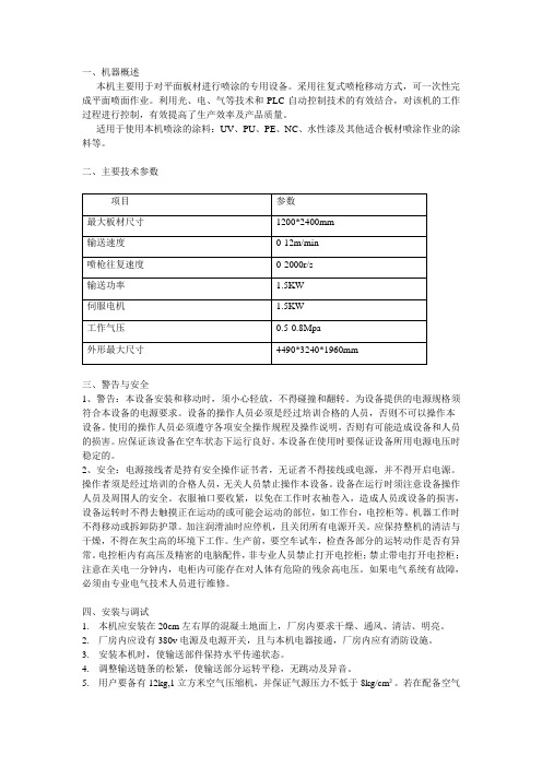
一、机器概述本机主要用于对平面板材进行喷涂的专用设备。
采用往复式喷枪移动方式,可一次性完成平面喷面作业。
利用光、电、气等技术和PLC自动控制技术的有效结合,对该机的工作过程进行控制,有效提高了生产效率及产品质量。
适用于使用本机喷涂的涂料:UV、PU、PE、NC、水性漆及其他适合板材喷涂作业的涂料等。
二、主要技术参数三、警告与安全1、警告:本设备安装和移动时,须小心轻放,不得碰撞和翻转。
为设备提供的电源规格须符合本设备的电源要求。
设备的操作人员必须是经过培训合格的人员,否则不可以操作本设备。
使用的操作人员必须遵守各项安全操作规程及操作说明,否则有可能造成设备和人员的损害。
应保证该设备在空车状态下运行良好。
本设备在使用时要保证设备所用电源电压时稳定的。
2、安全:电源接线者是持有安全操作证书者,无证者不得接线或电源,并不得开启电源。
操作者须是经过培训的合格人员,无关人员禁止操作本设备。
设备在运行时须注意设备操作人员及周围人的安全。
衣服袖口要收紧,以免在工作时衣袖卷入,造成人员或设备的损害,设备运转时不得去触摸正在运动的或可能会运动的部位,如工作台,电控柜等。
机器工作时不得移动或拆卸防护罩。
加注润滑油时应停机,且关闭所有电源开关。
应保持整机的清洁与干燥,不得在灰尘高的坏境下工作。
生产前,要空车试车,检查各部分的运转动作是否有异常。
电控柜内有高压及精密的电脑配件,非专业人员禁止打开电控柜;禁止带电打开电控柜;注意在关电一分钟内,电柜内可能存在对人体有危险的残余高电压。
如果电气系统有故障,必须由专业电气技术人员进行维修。
四、安装与调试1.本机应安装在20cm左右厚的混凝土地面上,厂房内要求干燥、通风、清洁、明亮。
2.厂房内应设有380v电源及电源开关,且与本机电器接通,厂房内应有消防设施。
3.安装本机时,使输送部件保持水平传递状态。
4.调整输送链条的松紧,使输送部分运转平稳,无跳动及异音。
5.用户要备有12kg,1立方米空气压缩机,并保证气源压力不低于8kg/cm²。
ZB-80等离子设备配置及技术参数表
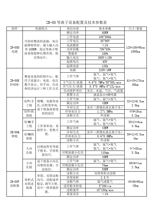
ZB-80等离子设备配置及技术参数表组件性能特点项目内容基本参数尺寸/重量流化床式双筒送粉器单筒、双筒送粉均可,送粉速率范围广,易损件少。
送粉方式流化床式送粉82*30*45cm20kg单筒容积2升送粉气体氩气或氮气适用粉末粒度5~200μm送粉速率15~300g/min重复误差<3%ZB-80ZJX 转接箱喷涂系统的转接中心,它把电源、控制柜、喷枪、热交换器连接在一起,内装有高频点火、水路报警。
控制方式外部控制柜控制75*36*170cm35kg耐冷却水压力 1.5MPa冷却水压保护0.5~1MPa点火电压3000VZB-80R 热交换器水泵式热交换器进口高压水泵,内循环水冷却喷枪,外循环水冷却内循环水,成本低,适合北方使用。
制冷方式热交换130*80*100cm200kg冷却能力30KW电源3P/380V/8KW水泵流量8~20L/min输出压力0~0.8MPa温控范围20~38℃氟利昂冷冻式冷水机压缩机、水泵、换热器均为进口部件,可按需要调节水温、水压,具有自动调节水温功能。
制冷方式氟利昂压缩机制冷180*90*180600kg冷却能力35KW电源3P/380V/15KW水泵流量10~30L/min输出压力0~1.5MPa温控范围5~35℃等离子喷涂设备2007-11-3 9:46:40一、ZB-80型等离子喷涂系统等离子喷涂系统构成ZB-80F送粉器ZB-4FL送粉器该设备与PT-A3000或METCO 9M等离子喷涂系统技术水平相当。
电源采用可控硅整流,最大输出功率80KW,最大电流1000A,采用“软起弧”;喷枪有9M、F4、F1等多种配置,喷嘴、电极寿命长;送粉器有容积式、流化床式等三种配置,可满足用户的不同需求;控制系统有继电器、可编程控制器等多种配置,具有水、电、气安全报警功能,可实现喷涂自动程序控制。
该喷涂系统适于喷涂金属氧化物陶瓷、碳化物硬质合金、各种金属及合金等。
ZB-80K控制柜 9M手工枪 9M机装枪F4手工枪 F4机装枪 F1内孔枪各种喷枪配件《ZB-80 等离子设备配置及技术参数表》.doc 下载二、ZB-200型高能等离子喷涂设备该设备具有“一机多用”的特点。
等离子喷涂

等离子喷涂车应用材料尚雪莉车辆工程1班20124319等离子喷涂尚雪莉20124319车辆工程1班等离子喷涂等离子喷涂是一种材料表面强化和表面改性的技术,可以使基体表面具有耐磨、耐蚀、耐高温氧化、电绝缘、隔热、防辐射、减磨和密封等性能。
等离子喷涂技术是采用由直流电驱动的等离子电弧作为热源,将陶瓷、合金、金属等材料加热到熔融或半熔融状态,并以高速喷向经过预处理的工件表面而形成附着牢固的表面层的方法。
等离子喷涂亦有用于医疗用途,在人造骨骼表面喷涂一层数十微米的涂层,作为强化人造骨骼及加强其亲和力的方法。
1.概述等离子喷涂技术是继火焰喷涂之后大力发展起来的一种新型多用途的精密喷涂方法,它具有:①超高温特性,便于进行高熔点材料的喷涂。
②喷射粒子的速度高,涂层致密,粘结强度高。
③由于使用惰性气体作为工作气体,所以喷涂材料不易氧化。
喷涂原理等粒子喷涂是利用等离子弧进行的,离子弧是压缩电弧,与自由电弧相比较,其弧柱细,电流密度大,气体电离度高,因此具有温度高,能量集中,弧稳定性好等特点。
按接电方法不同,等离子弧有三种形式:①非转移弧:指在阴极和喷嘴之间所产生的等离子弧。
这种情况正极接在喷嘴上,工件不带电,在阴极和喷嘴的内壁之间产生电弧,工作气体通过阴极和喷嘴之间的电弧而被加热,造成全部或部分电离,然后由喷嘴喷出形成等离子火焰(或叫等离子射流)。
②转移弧:电弧离开喷枪转移到被加工零件上的等离子弧。
这种情况喷嘴不接电源,工件接正极,电弧飞越喷枪的阴极和阳极(工件)之间,工作气体围绕着电弧送入,然后从喷嘴喷出。
③联合弧:非转移弧引燃转移弧并加热金属粉末,转移弧加热工件使其表面产生熔池。
这种情况喷嘴,工件均接在正极。
等粒子喷涂设备:等离子喷涂设备主要包括:①喷枪:实际上是一个非转移弧等离子发生器,是最关键的部件,其上集中了整个系统的电,气,粉,水等。
②电源:用以供给喷枪直流电。
通常为全波硅整流装置。
③送粉器:用来贮存喷涂粉末并按工艺要求向喷枪输送粉末的装置。
喷涂设备使用说明书
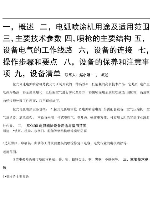
一,概述二,电弧喷涂机用途及适用范围三,主要技术参数四,喷枪的主要结构五,设备电气的工作线路六,设备的连接七,操作步骤和要点八,设备的保养和注意事项九,设备清单联系人:赵小姐一,概述拉式高速电弧喷涂机是我公司研制开发的一种高效率、低能耗的高新技术产品。
它是以电产生电弧为热源,将金属丝熔化,以压缩空气进行雾化及冷却,将需喷涂用金属丝吹成微细颗粒,高速喷向经过预处理工件表面,获得理想涂层。
拉式电弧喷涂设备包括: 1.拉式电弧喷涂枪 2.电弧喷涂电源另需配套设备:空气压缩机、空气滤清器、放丝盘架。
本设备采用一体式电控气、电开关,操作更方便。
可实现长距离登高作业或野外作业。
二,SX400 电弧喷涂设备用途与适用范围用途: •铁塔、桥梁、水闸门、船舶等钢结构喷锌喷铝防腐•造纸烘缸、印刷辊、曲轴等工件表面磨损的喷涂修复•电容、电瓷行业的电极喷涂等。
适用范围:该类电弧喷涂机可喷的材料如:锌,铝,铅锡合金,铜,炭钢,不锈钢等。
三,主要技术参数1•喷枪的主要参数2. 电源的主要参数重量:278KG左右其它参数特点:i.适用拉式或推式电弧喷枪.2•该电源将喷枪工况控制、送丝调速、气体管路集于一身,是理想的电弧喷涂专用设备。
3.控制与操作特别简单,只要拨动喷枪上的开关即可实现与远端的电源开关的同步控制四、拉式喷枪的主要结构(图一)1. 喷头组件:它是汇集气、电的独立单元组件,由下列主要元件组成:A、弧光罩:起遮蔽弧光作用,在130 度范围内弧光不向操作者照射。
B、前导管组件:采用导电性能好的耐磨材料制成,它起到使两根线材迫交的导向作用,也是磨损更换零件之一,一般情况下,更换时只需换导管端头铜制件(连接咀)即可。
C、调节空气帽采用陶瓷材料制成,其外径为:M39*1.5 螺纹可作轴向自由调节。
一般可调节到二线交汇点到空气帽平面之距离为1-3 毫米(见示意图),如二线交点在空气帽内,则会产生爆鸣和“涂层积口”如二线交点远离空气帽平面,则产生的涂层较粗。
反应等离子喷涂技术要求
反应等离子喷涂技术要求反应等离子喷涂技术是一种先进的表面涂层技术,它通过将粉末材料加热至高温并喷射到基材表面,形成坚固的涂层。
这种技术在航空航天、能源、汽车和冶金等领域具有广泛的应用。
反应等离子喷涂技术的要求主要包括以下几个方面:1. 材料选择:反应等离子喷涂技术可以使用多种材料进行涂层,如金属、陶瓷、合金等。
在选择材料时需要考虑涂层的性能要求以及基材的特性。
不同材料具有不同的耐磨、耐腐蚀和导热性能,因此需要根据具体应用场景选择合适的材料。
2. 设备要求:反应等离子喷涂技术需要使用专用的喷涂设备,如等离子喷涂机。
这种设备能够产生高温等离子体,并将粉末材料加热至高温后喷射到基材表面。
设备的性能和稳定性对于涂层质量和生产效率至关重要,因此需要选择高质量的设备。
3. 工艺参数:反应等离子喷涂技术的工艺参数对于涂层质量有重要影响。
工艺参数包括喷涂速度、喷涂距离、气体流量、等离子体功率等。
这些参数的选择需要根据材料和涂层要求进行优化,以确保涂层的致密性、附着力和均匀性。
4. 表面准备:在进行反应等离子喷涂之前,需要对基材表面进行准备。
这包括去除表面的油污、氧化物和其他杂质,以确保涂层与基材之间的良好结合。
常用的表面准备方法包括喷砂、化学清洗和机械打磨等。
5. 涂层性能测试:为了评估反应等离子喷涂涂层的质量,需要进行一系列的性能测试。
常见的测试方法包括硬度测试、附着力测试、耐磨性测试和耐腐蚀性测试等。
这些测试可以用来评估涂层的耐用性、耐磨性和化学稳定性。
6. 质量控制:在进行反应等离子喷涂过程中,需要进行严格的质量控制,以确保涂层的一致性和稳定性。
这包括对原材料进行质量检查、设备运行状态的监控和涂层质量的检验。
只有通过质量控制,才能保证反应等离子喷涂技术的应用效果。
总结起来,反应等离子喷涂技术要求选择合适的材料,使用高质量的设备,优化工艺参数,进行表面准备,进行涂层性能测试,并进行严格的质量控制。
只有满足这些要求,才能获得高质量的涂层,提高产品的性能和使用寿命。
自动喷漆机操作手册说明书
The terminology of the future manufacturing state – Industry 4.0, 4IR, Fourth industrial revolution, Industrial Internet of Things, cyber physical systems, machine learning – has become a new industrial language which has lost many of its target audience. While most engineers and manufacturing executives know of these terms, the jargon can be confusing and off-putting to many companies, especially SMEs, who simply want to know: what does it do and what is the value proposition?Autodesk and KUKA Robotics UK have combined to explain how some of the new digital technologies that will transform manufacturing – including cloud computing, digital twins, generative CAD design and collaborative robots – really work and what they can do for smaller companies. Our chosen approach is not to baffle the end-user with buzzwords but explain the technology and the opportunities and how companies are using it.Some of the central terms in the Industry 4.0 lexicon are really important to manufacturing industry as it evolves.A gility, for example, refers to the greater responsiveness of factories to consumer demands. While mass personalisation is still in its early stages, and is better suited so far to consumer durables like cars than commodity goods, digital technology is and will be needed in manufacturing lines for products like cosmetics and soft drinks, where the same dispensers can fill bottles in series with different fluids to ship mixed batches, reducing packing time. KUKA Smart Production says that tomorrow “product lifecycles will be shorter than the lifetime of the production system”.D igital twins are the simulated offline versions of real parts and assemblies that reveal how they physically behave before they are manufactured. This technology is getting very sophisticated so engineers can test a wider range of physical and mechanical performance metrics offline before the cost of making the first one-offs.T he cloud factory – really means a factory where the operational data needed to run machines and processes are stored in the cloud, rather than a fixed data centre. Cloud access becomes very relevant in a machine learning environment, when machines like robots are expected to “learn” new actions by interpreting data from their environment, such as face recognition to work alongside a human operative. The cloud enables the passage of operating data to the ‘deep learning’ phase of machine learning, and to feed this back to a robot to optimise its next operation.OBJECTIVEThese connected factory technologies are not being developed to force or scare companies into buying more software or equipment. They are here to solve real world problems.KUKA’s Industrie 4.0 and Smart Factory report summarises this nicely. By 2025, in just eight years, there will be about 8 billion people in the world, half of them in the “Consumer Class”, people who routinely purchase items like consumer durables (cars, white goods etc). Populations are aging, and the population in Germany and some developed countries is slowing or shrinking. If manufacturing productivity in high cost countries does not improve there may be more offshoring to low cost countries – even though there is evidence of reshoring production from Asia. There is a growing demand for personalization of mass produced products, we want to customize what we buy – only automation can do this economically. Robots and other machines will be used as “assistant systems” for workers, aka the Human Robot Cooperativte.More drivers for the “fourth industrial revolution” are well documented. In short, digital technology can keep manufacturing viable in developed countries and deliver the customisation that people want, economically, with more variety than has been possible, with an often ageing and “manufacturing-neutral” workforce. The last point refers to the manufacturing recruitment challenge; if countries like the UK cannot attract more people to work in factories, technology will have to do the work.BACKGROUND World Population B illion People Below Consumer Class Consumer Class % Population in Consumer Class 1950132.5 3.7 5.3 6.87.91970231990232010362025532.2 2.8 4.0 4.43.70.90.3 1.2 2.44.2Production agility and market responsiveness.Quite simply, companies will need to be more agile to respond to changing product iterations and varying demand volumes more quickly in the future. Part of the key is to connect devices to give factories more information.The Internet of Things, as we know, is about connecting industrial devices together. How does this translate into better business?One area is connecting customer demands to production. Companies now want to re-iterate their products quickly; they cannot afford to be tied into rigid production processes to make colossal quantities of products of each iteration, if consumer tastes or design intent changes mid-run.“The challenge facing industry is how can we make manufacturing processes more nimble so they can support the more nimble approach to product evolution?” says Steve Hobbs, Vice President of CAM and Hybrid Manufacturing at panies like Autodesk and KUKA are addressing this in two main ways:1) A pply one-off prototyping / tool-making technology into volume production The kind of CNC devices commonly used in tool rooms and job shops were all about making one-offs. This needs quite deep knowledge to, for example, make an intricate mould tool that will mould a million parts. The tool-making knowhow needs to be applied more quickly to mass production.2) R obot reprogramming Typically an industrial robot is not treated as a reprogrammable device.It would be programmed in situ in a sequence of specified moves, also known as the teach pendant. The robot performs one operation like spot welding or lifting until it gets scrapped because a new line is started elsewhere. CNC machine tools are very much reprogrammable devices.CHANGING THE RULES OF THE GAME “We want to apply the technology we use with CNC cutting for example to make it much easier for robots and other automation devices to be reprogrammed on the fly.” Steve Hobbs Vice President of CAM and Hybrid Manufacturing | Autodesk The better use of, the optimisation of, robots to do things beyond their original sequential task remit is a key part of the Industry 4.0 evolution. KUKA is using new digital tools to programme ultra-efficient smart factories covering key technologies such as mobile robotics, machine learning, reconfigurable production cells and collaborative robots. The rapid growth in the versatility of robots in recent years is remarkable, driven by the need for agile manufacturing.“Industry 4.0 should not be seen as a solution or product, per se,” says Jeff Nowill, CEO of KUKA Robotics UK and KUKA Ireland.“It is a way of making any manufacturing environment more market and demand appropriate by employing technology to seamlessly and automatically improve cycle time, batch-magnitude, process characteristics, quality or manifestly change output according to – or even anticipating –demand. As such, it is a vehicle to be a better manufacturer, but it’s primarily about having the right value-proposition to start off with.”Key business benefit: Production can be completed more quickly than it can in “analogue” or unconnected factories, delivering greater variation to customers in high volume, while simultaneously increasing speed and reducing waste.Agility: Companies cannot afford to be tied into your production processes to make colossal quantities of those products on each iteration.Build and test offline.An essential point of smart factory technology is the ability to design and test products – and their manufacturability – offline before anything is made for real.“We cannot experiment with the physical equipment, because if we take down the production line we will be losing output and we kill the economy of scale. Stopping an automotive plant can cost £10,000 a minute,” says Bart Simpson, Senior Director, Operations at Autodesk.Much of the 3D design, physical property analysis (FEA), and factory performance simulation can be done offline with a digital twin, a digital replica of the part or machine on screen, with all its working parts. These tools allow engineers to get, often complex, products right first time without building a prototype.“Making one-offs in tool rooms, you cannot do trial and error. If you made a part and “try it out” before you make the one-off, you have put 100% overhead on your process. So you need tools to make sure you get it right first time.”Steve Hobbs Vice President of CAM and Hybrid Manufacturing | Autodesk But engineering simulation (CAD and CAE) have been around for years. The next “Industry 4.0” phase requires two things:1) R icher simulation tools Autodesk now has clever simulation tools for metal cutting, and additive manufacturing processes, as well as more traditional finite element analysis tools.2) H igher accuracyBetter technology means greater assurance that these simulations are aligned to what actually happens in production DIGITAL TWINS Image courtesy of Briggs Automotive Company Ltd.“Smart factories are about connecting devices, ” says Bart Simpson. “Connecting devices has been around for some time but it has been difficult to glue those connections together and aggregate data in a meaningful way. Now this is possible.”Such powerful simulation also benefits factory planning and robotic operations. A big area for the smart factory is standardised Business benefit: Next generation software can interrogate parts, products, machines and factories to reveal design flaws and cost-saving solutions more accurately and quickly than was previously possible.What is my data and where does it go?The data in a machine shop environment includes spindle speeds, number of revolutions, temperature, coolant temperature and levels, tool wear, tool changeover intervals and machine running time. Also parts produced in a shift and quality C controllers are powerful computers in their own right. Under business-as-usual or “Industry 3.0”, many machine operators are not using them to the potential, rather just as a programmable interface. Inside the CNC are gigabytes of useful performance data.Let’s compare two scenarios, business as usual and Industry 4.0.Industry 3.0 machining In a traditional CAD/CAM environment, one would programme a part, generate the G code to drive the machine, and typically get an inaccurate estimate of how long it would take to cut the part.“The reason for this is that we don’t have real performance data for that machine,” says Steve Hobbs. “It has finite spindle acceleration and processing time for the CNC controller, things which mean it does not move instantaneously. In reality parts will take longer to cut than we expect.”Engineers build in fudge factors that add e.g. 20% to the expected time, but it is hit or miss.THE FACTORY AND DATA “Industry 4.0” machining This is Industry 3.0 with feedback.Machine performance data can predict how long a job will take. The job is run on the machine, live feedback from the machine measures how long it took and the operator can start to correlate the results and learn from them. Engineers can use simple manual correlations or a smarter machine learning approach to collect the data.Virtuous circle: When companies can feedback thetrue experience data from their factories, they can improve the quality of their digital model used to simulate that facility and therefore the accuracy of the simulation and the reliability of the results can be improved. The aim is a “virtuous digital circle” where the simulated production processes are a much more faithful representation of what will really happen on the shop floor, eliminating guess work.Business benefit: “The advantage is to harness manufacturing data and make it visible, in real-time across the supply chain. The benefit is to connect people, data, and machines to improve production efficiency, better decision making and enable an agile response to demand.”Cloud computing has also become a buzzword and there is a spectrum of true understanding of its role in smart factories.By using a cloud platform, or simply, moving and storing industrial data offline using the internet or local network as a interface, the wireless connections between the product and machines at the “field level” can speak instantly to the enterprise level systems like ERP and MES SCADA systems at the top level of the enterprise.In yesterday’s regime, product and field data – such as product defects, machine optimisation data like spindle speed and temperature – remained on the shop level and had to be manually fed into an enterprise IT system.Architectures like KUKA’s Edge Cloud Gateway does all this automatically. A board meeting can pull up real-time shop floor KPIs as the line is running, from the ERP system. The cloud makes this possible.“The driver for Industry 4 is the desire to use technology to the point where it becomes easier to connect the operation via cloud connections, and we can aggregate data much more easily where, with for example Autodesk Fusion 360 Production and other cloud tools, you can pull the data in from different factory sources to a database and you can start to link that data together, recognise patterns and see trends,” says Steve Hobbs, Autodesk.Business benefit: The I4.0 difference is that finally the process interrogation that manufacturing engineers have discussed for years are feasible because they have access to connectivity that they never had before. The cloud enables this.WHAT IS THE CLOUD FACTORY“Industry 4.0” factory and logistics technologies are enablers for mould-breaking businesses that disrupt established norms.Jeff Nowill of KUKA Robotics points to disruptive businesses that rebuild traditional systems, that think like their customers and which are brave enough to remodel their manufacturing and distribution to deliver this, rather than hope people will accept their rigid system.“Again, companies need the right value-proposition to begin with. That’s a case of understanding the complex relationship between your product or service within the context of your market, customers, competitors and the prevailing and future political climate. That gets a class-leading value-proposition to the table and thereafter, Industry 4.0 and its associated digital technologies can come into their own to ensure the application of the value proposition is world class. Zara the clothing business is a great example of this.”In 1990 Zara adopted a just-in-time (JIT) system, modified from the Toyota Production System. It enabled the company to establish a business model that allows self-containment through the stages of materials, manufacture, product completion and distribution to stores worldwide within just a few days. After products are designed they take 10 to 15 days to reach the stores. All of the clothing is processed through the distribution centre in Spain and in most cases, the clothing is delivered within 48 hours. Zara produces over 450 million items per year. Reportedly, Zara needs just one or two weeks to develop a new product and get it to stores, compared to the six-month industry average, and it launches around 12,000 new designs each year.To integrate such demanding manufacturing and delivery schedules, companies will need to integrate smart factory technology with smart logistics solutions and equipment such Swisslog’s automated picking robots and warehouse management. A good example of fully automated fulfilment in UK retail is Ocado, which picks all its orders and navigates its huge warehouse automatically.NEW BUSINESS MODELSMyth busting: Robots create jobsDespite the common belief that automation removes jobs in the automotive industry, the opposite is happening in Germany and some nations. From 2010-2015, the number of employees in the German automotive industry expanded by 14% to reach 710,000 workers by late 2016 (Source: Euromonitor).ZND UK in Rotherham is Europe’s largest manufacturer of temporary fencing and pedestrian barriers. Since 2012 it has had a fully automated robot-operated line to feed wire coil to the fence assembly process, to braze on supports, further value-add operations and handle the material between cells. Engineering manager Paul Fenwick says without the KUKA robotic line, the process would need 16-men per shift. With robots, throughput has risen from 80 per line per shift, to 500 per line per shift – a rise of 600%. Robotic brazing has created a better product, so demand has increased, meaning more recruitment to man the lines. For ZND, the term “Industry 4.0” may be irrelevant but by automating the factory fully it has raised output to meet demand, increased quality and created jobs.KUKA CASE STUDY - ZND UKReference linksI ndustrie 4.0 and collaborative robots in German car industry /2016/10/industry-4-0-german-car-industry-introduces-collaborative-robots.htmlH ow robots will change the workforce /news/2016-12-robots-workforce.htmlT he Ocado warehouse run by robots /news/av/business-38897417/the-ocado-warehouse-run-by-robots T he Zara business model /why-zara-is-crushing-the-retail-industry-2016-5S eeing Digital Twin Doublehttp://www.digitaleng.news/de/seeing-digital-twin-double Coming Up Next…..The second Autodesk and KUKA Robotics paper on Deciphering Industry 4.0 will investigate: HUMAN AND ROBOT COLLABORATIONAs manufacturing companies seek to automate the assembly of products more and more, human and robot collaboration is a growing field. Companies that are used to assembling complex structures fully manually know that one way to increase throughput is to develop reliable and safe systems where humans and robots can work side-by-side.Much research is being done in this area, in the UK especially at Cranfield and Loughborough universities, and more companies are installing collaborative robots, or “cobots”, to assist workers with desk-based and light, repetitive assemblies and inspection tasks.Our white paper discusses the latest advances in this field and demonstrates the business case.Expect the next paper out in SEPTEMBER 2017.Our third paper will continue to explore Smart Logistics and Mass Customisation and our fourth paper will discuss Generative Design & Artificial Intelligence.We hope you have found this white paper useful.Please get in touch with Autodesk and KUKA Robotics if you wish to discuss any part of this report further. 。
等离子喷涂设备操作规程

等离子喷涂设备操作规程1.打开气瓶并达到指定压力指数。
(注:更换气瓶后或定期采用泡沫水检查气体是否存在泄漏情况,并应及时排除。
)2.打开冷水机电闸和开关,双压缩指示灯要亮,查看冷却水压力表一般到达0.9左右,如达不到则拆卸开冷却水箱东下侧的侧盖板,调节内侧的阀门,并观察冷却水压力表到达0.9为止。
3.打开等离子电源,并用手触摸等离子电源箱上侧的排风口是否有风被排出。
4.开启控制柜电源,打开“急停”按钮,检查所有气体压力参数是否达到指定的标准,点击“解除报警”。
(如报警无法解除,则点击“菜单”中的“故障报警”,查看故障并根据显示屏提示的故障解除故障。
)5.报警解除后,点击“净化”3~5秒钟,并查看净化过程中喷嘴和枪体是否有漏水现象。
(如有漏水现象,则按下“急停”按钮,拆卸喷枪,检查喷枪内是否有密封圈损坏,并及时更换。
)6.净化后如无漏水,请点击“高频测试”检查喷嘴与电极头和转接箱内是否有放电现象。
(如无放电现象,先按下“急停”按钮,若转接箱内无放电现象,用砂纸打磨点火柱间的缝隙;若喷嘴内无放电现象,则拆卸喷嘴,用砂纸打磨喷嘴外套内侧。
)7.喷嘴出现高频后,点击“启动”并观察喷涂电压值。
(注:观察喷涂电压值时,把手放在“急停”按钮旁边,以防出现故障时,可以迅速按下“急停”按钮。
)8.待火焰稳定后,输入你所需要的喷涂功率(电流和电压)后,点击“确定”,喷枪会立即达到你所设定的功率值,如需要50V左右的小电压,应该采用增减氢气流量的方法达到你所需要的电压;55V以上电压可直接输入、确定,也可微调氢气流量,达到喷涂电压的准确度。
9.根据喷涂所需要的材料所在的送粉筒,按下“送粉1”或“送粉2”,并打开送粉器上的送粉开关,检查送粉器是否送粉均匀连续。
(注:此送粉测试可在点火前打开“急停”,打开送粉开关,若送粉均匀正常才可点火。
)10.火焰有粉末后,看火焰颜色是否正常,调节送粉大小或看送粉陶瓷嘴是否对准火焰中心;查看送粉气体流量大小以及压力。
ZB80等离子喷涂说明书

ZB-80热喷涂设备操作说明书河北科技大学北京航天振邦精密机械有限公司ZB-80热喷涂设备操作说明书一、概述ZB-80热喷涂设备主要包含以下部分:电源、控制柜、热交换器、转接箱、喷枪和送粉器。
其中需要操作的主要有控制柜、喷枪和送粉器,其他部分在设备调试完毕后基本不再需要进行调整。
本操作说明书主要是针对喷枪和控制柜的操作进行说明,送粉器的操作请参看送粉器使用说明书。
二、操作须知ZB-80热喷涂设备的操作人员必须是经过培训并通过认证的专业人员,在进行热喷涂工作之前必须熟悉以下事项方可进行工作:1.安全防护1.1喷涂操作间的通风等离子喷涂时产生大量的烟尘,操作间必须配备通风系统,以排除毒性气体和粉尘。
1.1.1如果在机床上进行喷涂操作,吸尘罩最好能装在托架的后面以便使它能与喷枪一起运动,将喷涂时产生的粉尘和烟雾抽进或收集到粉尘集收器中。
1.1.2 用于喷涂中小尺寸零件的喷涂柜应安装排气通风装置,进入罩子的空气流速为45~120m/min。
喷涂毒性材料时,空气流速应达到120m/min。
1.1.3喷涂操作间通风时,换进的空气要确保清洁、新鲜。
1.1.4在打扫操作间时,要保持通风机在工作状态,以防止粉尘和烟气的聚集。
要特别注意铝和镁的粉尘有爆炸的危险,这两种金属的粉尘要用合适的湿式集收器。
这些金属的粉尘在水中能产生氢气,这种湿式集收器要能防止氢在其中的聚集,要经常进行清除工作,减少铝和镁的残留物。
1.2 防火、防爆措施1.2.1 不要在喷涂室内使用易燃溶剂清洗工件,清洗场所要通风良好。
1.2.2空气中粉尘或一些特殊金属粉易引起爆炸,应在操作场安装通风设备,建议用水洗湿式除尘器收集喷涂粉尘。
对工作场地和设备要经常打扫,防止粉尘的聚集。
1.2.3等离子喷枪焰流温度高达7000~10000℃,不要将正在操作的喷枪对着人或易燃材料。
工作场地内不准有易燃物。
1.2.4热喷涂隔音室应用防火材料制成。
1.2.5要定期检查等离子气体和空气管路,压缩机调压器等,以防止泄漏和联结部件的松动。
ZB-80等离子设备配置及技术参数表

ZB-80等离子设备配置及技术参数表组件性能特点项目内容基本参数尺寸/重量流化床式双筒送粉器单筒、双筒送粉均可,送粉速率范围广,易损件少。
送粉方式流化床式送粉82*30*45cm20kg单筒容积2升送粉气体氩气或氮气适用粉末粒度5~200μm送粉速率15~300g/min重复误差<3%ZB-80ZJX 转接箱喷涂系统的转接中心,它把电源、控制柜、喷枪、热交换器连接在一起,内装有高频点火、水路报警。
控制方式外部控制柜控制75*36*170cm35kg耐冷却水压力 1.5MPa冷却水压保护0.5~1MPa点火电压3000VZB-80R 热交换器水泵式热交换器进口高压水泵,内循环水冷却喷枪,外循环水冷却内循环水,成本低,适合北方使用。
制冷方式热交换130*80*100cm200kg冷却能力30KW电源3P/380V/8KW水泵流量8~20L/min输出压力0~0.8MPa温控范围20~38℃氟利昂冷冻式冷水机压缩机、水泵、换热器均为进口部件,可按需要调节水温、水压,具有自动调节水温功能。
制冷方式氟利昂压缩机制冷180*90*180600kg冷却能力35KW电源3P/380V/15KW水泵流量10~30L/min输出压力0~1.5MPa温控范围5~35℃等离子喷涂设备2007-11-3 9:46:40一、ZB-80型等离子喷涂系统等离子喷涂系统构成ZB-80F送粉器ZB-4FL送粉器该设备与PT-A3000或METCO 9M等离子喷涂系统技术水平相当。
电源采用可控硅整流,最大输出功率80KW,最大电流1000A,采用“软起弧”;喷枪有9M、F4、F1等多种配置,喷嘴、电极寿命长;送粉器有容积式、流化床式等三种配置,可满足用户的不同需求;控制系统有继电器、可编程控制器等多种配置,具有水、电、气安全报警功能,可实现喷涂自动程序控制。
该喷涂系统适于喷涂金属氧化物陶瓷、碳化物硬质合金、各种金属及合金等。
ZB-80K控制柜 9M手工枪 9M机装枪F4手工枪 F4机装枪 F1内孔枪各种喷枪配件《ZB-80 等离子设备配置及技术参数表》.doc 下载二、ZB-200型高能等离子喷涂设备该设备具有“一机多用”的特点。
等离子喷涂基体最低温度

等离子喷涂基体最低温度
等离子喷涂基体最低温度是指进行等离子喷涂时,需要达到的最低工作温度。
等离子喷涂是一种高温、高速度的表面涂覆技术,常用于增强材料表面的性能,提高耐磨、耐腐蚀等特性。
但是,由于材料的物理特性和化学特性的不同,进行等离子喷涂时需要设定不同的工作温度,以保证喷涂效果和材料性能的兼容性。
一般来说,等离子喷涂的基体最低温度是在500℃到800℃之间,但具体的温度要根据喷涂材料的种类、形态和表面状态等因素而定。
在实际工作中,需要根据不同的应用场景和要求进行温度的调节和控制,以达到最佳的涂覆效果和材料性能。
- 1 -。
- 1、下载文档前请自行甄别文档内容的完整性,平台不提供额外的编辑、内容补充、找答案等附加服务。
- 2、"仅部分预览"的文档,不可在线预览部分如存在完整性等问题,可反馈申请退款(可完整预览的文档不适用该条件!)。
- 3、如文档侵犯您的权益,请联系客服反馈,我们会尽快为您处理(人工客服工作时间:9:00-18:30)。
ZB-80热喷涂设备操作说明书河北科技大学北京航天振邦精密机械有限公司ZB-80热喷涂设备操作说明书一、概述ZB-80热喷涂设备主要包含以下部分:电源、控制柜、热交换器、转接箱、喷枪和送粉器。
其中需要操作的主要有控制柜、喷枪和送粉器,其他部分在设备调试完毕后基本不再需要进行调整。
本操作说明书主要是针对喷枪和控制柜的操作进行说明,送粉器的操作请参看送粉器使用说明书。
二、操作须知ZB-80热喷涂设备的操作人员必须是经过培训并通过认证的专业人员,在进行热喷涂工作之前必须熟悉以下事项方可进行工作:1.安全防护1.1喷涂操作间的通风等离子喷涂时产生大量的烟尘,操作间必须配备通风系统,以排除毒性气体和粉尘。
1.1.1如果在机床上进行喷涂操作,吸尘罩最好能装在托架的后面以便使它能与喷枪一起运动,将喷涂时产生的粉尘和烟雾抽进或收集到粉尘集收器中。
1.1.2 用于喷涂中小尺寸零件的喷涂柜应安装排气通风装置,进入罩子的空气流速为45~120m/min。
喷涂毒性材料时,空气流速应达到120m/min。
1.1.3喷涂操作间通风时,换进的空气要确保清洁、新鲜。
1.1.4在打扫操作间时,要保持通风机在工作状态,以防止粉尘和烟气的聚集。
要特别注意铝和镁的粉尘有爆炸的危险,这两种金属的粉尘要用合适的湿式集收器。
这些金属的粉尘在水中能产生氢气,这种湿式集收器要能防止氢在其中的聚集,要经常进行清除工作,减少铝和镁的残留物。
1.2 防火、防爆措施1.2.1 不要在喷涂室内使用易燃溶剂清洗工件,清洗场所要通风良好。
1.2.2空气中粉尘或一些特殊金属粉易引起爆炸,应在操作场安装通风设备,建议用水洗湿式除尘器收集喷涂粉尘。
对工作场地和设备要经常打扫,防止粉尘的聚集。
1.2.3等离子喷枪焰流温度高达7000~10000℃,不要将正在操作的喷枪对着人或易燃材料。
工作场地内不准有易燃物。
1.2.4热喷涂隔音室应用防火材料制成。
1.2.5要定期检查等离子气体和空气管路,压缩机调压器等,以防止泄漏和联结部件的松动。
1.2.6清扫喷涂柜或通风管路时,要保持通风风机工作,防止易燃、易爆物堆积过多引起爆炸。
1.2.7 不允许将喷枪或其管线,悬挂于气瓶的开关或减压器上。
1.2.8 气体管路及减压器不得接触任何油脂。
1.3 人身安全1.3.1喷涂过程中,面罩、护目镜应配以适当深度的滤色片以保护眼睛,镜片的深度参照GB3609.1。
1.3.2等离子喷涂操作时,要求带头盔或面罩,防止紫外线和红外线辐射的灼伤。
1.3.3喷涂操作人员应使用防尘口罩;当防尘口罩无法挡住粉尘时,可用机械式过滤呼吸器(含有活性碳)。
1.3.4等离子喷涂或吹砂时,操作者应佩戴护耳器或合适的软橡皮耳塞以避免高分贝噪音对听力的损害。
1.3.5根据喷涂工作的轻重、性质、施工条件来选择合适的喷涂和喷砂服。
在没有专用的喷涂服时,可用焊工工作服。
1.3.6在工作间进行毒性材料的喷涂时,要有特殊安全措施,操作工使用过的衣服和呼吸系统保护设施应每天更换。
重复使用以前用过的衣服和呼吸系统保护设施要彻底清除掉有毒的金属粉尘和其他材料后方可重新使用。
1.3.7等离子喷涂操作工在手持喷枪操作时应戴绝缘手套。
1.3.8所有的电源都应该有可靠的接地。
1.4 毒性材料和其他危险材料所有的细粒状材料都会损坏人们的呼吸系统,喷涂工的保护方法应按所喷的材料的类型不同,而采取不同措施。
保护措施由适当的通风和合适的呼吸系统保护设施组成,当使用了这些保护设施而操作者仍觉不适时,应停止工作。
1.4.1有毒金属及其他化合物铍、铍化物、镉、铬、铅和铅合金都有剧毒,不论在室内室外喷涂这类材料或对之喷砂时,都应使用适当的局部通风器和空气管道呼吸器。
通风机的废气要安全管理,并直接排入安全地区。
任何情况下,邻位喷涂操作的工人也要有局部通风和空气管路呼吸系统。
1.4.2 有些塑料如聚乙烯、尼龙等烟气是无毒的,但气味对人不适,仍应抽风除去;有些塑料如聚氯乙烯、氟塑料等的烟气是有毒的,甚至是剧毒的,在喷涂时一定要有通风加呼吸系统保护施。
1.4.3溶剂等离子喷涂和电弧喷涂中的弧光辐射可引起溶剂蒸气迅速分解,成为有害气体,如三氯乙烯和过氯乙烯溶剂即使受到远处弧光的辐射,也会迅速分解产生碳酰氯气体。
在对用溶剂脱脂的工件进行喷涂时,要采取特别预防措施,在喷涂前应除去这些溶剂,要注意由工件的凹坑和裂缝中带进的液膜或溶剂珠滴。
1.4.4 锡和锌常以其气氧化物形式出现,它们本身虽是无毒的,但会引起突发性病痛。
三、ZB-80喷枪1、喷枪特性ZB-80Q等离子喷枪仿制于F4喷枪。
该喷枪设计精巧、结构紧凑、操作简便,正常检修只需更换喷嘴和电极头且拆装十分便利。
该喷枪工作稳定、性能可靠,最大功率可达50KW,能够获得高质量的陶瓷和金属涂层。
ZB-80Q喷枪分为机装枪(ZB-80QM)和手工枪(ZB-80QH)两种,ZB-80Q仿F4喷枪用氩气做主气,氢气做辅气。
2、喷枪结构ZB-80Q仿F4喷枪主要由前后枪体、绝缘体、喷嘴、电极组成。
ZB-80Q仿F4喷枪拆装非常简便,喷嘴和电极头都镶有钨套,因而喷嘴、电极寿命非常长,正常使用可达60小时以上。
该型号喷枪的水冷效果要比9M系列喷枪好,冷却水压力一般在1.1~1.5MPa。
3.喷枪的维护及其使用注意事项3.1常见故障及排除措施表1列出了喷涂操作过程中可能出现的一些故障及排除措施,以便于使用者迅速查明原因,及早排除故障。
表1 常见故障及排除措施3.2喷枪使用注意事项3.2.1喷嘴、电极头、绝缘体等零配件从枪上拆下后,应存放于专用容器内,避免磕碰或沾上灰尘。
3.2.2拆装喷枪时,应避免损伤各零配件的配合面。
3.2.3喷枪装配时应避免用力过大,适当用力拧紧即可。
3.2.4 某些零件的拆装需使用专用工具,错用工具往往造成不必要的损伤。
3.2.5拆解喷枪前应将其擦净,避免粉尘进入喷枪内部精密配合区域。
3.2.6每次拆解喷枪时应仔细检查所有的“O型圈”,一旦出现“切边”或“凹坑”必须立即更换。
3.2.7点枪前必须吹净喷嘴内的水滴,否则会造成喷嘴内壁的烧损。
3.2.8喷嘴每工作10h,旋转900可有效延长其使用寿命。
3.2.9装配喷枪时,“O型圈”部位应涂抹薄薄一层“密封脂”。
3.2.10长时间连续喷涂(>1h),喷嘴端面可能沾附一些粉末,应及时将其除去,以免影响涂层质量。
4.喷涂工艺参数常用粉末的等离子喷涂工艺参数详见附表四、ZB-80控制柜1、ZB-80控制柜的结构ZB-80控制柜是ZB-80热喷涂设备的控制部分,它控制着热交换器和主电源的启停及喷枪的工作状态。
ZB-80控制柜的外观如图5所示。
图5 ZB-80控制柜外观图2、ZB-80控制柜的操作步骤(即喷涂工作的步骤)2.1接通热交换器的外循环水路,接通和控制柜相连接的各个气路(氩气压力约0.6~0.7MPa,氮气压力稍低于氩气压力,氢气压力约0.3MPa),接通各用电设备的电源(电源需380V/80KW,热交换器需380V/25KW,控制柜需220V/1KW);2.2开启控制柜的电源开关,此时热交换器开始工作;2.3按下净化按钮直至喷枪内不再有水珠,如果能确保喷枪内没有水珠则可以省略此步骤;2.4按下高频检查按钮并观察转接箱内的火花间隙是否有电火花,同时观察喷枪内是否有电火花,喷枪内电火花不可太强,时断时续为佳。
如果电火花不正常,则调整火花间隙直至正常,如果设备一直处于正常使用,则可以省去此步骤;2.5按下主电源启按钮,主电源开始工作,控制柜上的电压表和电流表开始指示,此时观察控制柜上的液晶显示表,如果有报警显示(主气压力、主气流量、水压、水温报警),则对该项参数作适当的调整(主气流量应该设定在30~40升/分)。
2.6在电压表的读数稳定在60V左右的情况下,按下点火按钮,点燃喷枪(如果不能够点着喷枪,则按下主电源停按钮,重复步骤2.3和2.4);2.7喷枪点燃后,按下运行按钮,进入运行状态;根据电压调节氢气流量;2.8将氮氩转换开关放置到“氮气”的位置(仅限于9M喷枪配备氮气绝缘体和喷嘴),此时开始喷涂工作;2.9喷涂工作完成后,将氮氩转换开关放置到“氩气”的位置,依次按下运行停按钮和主电源停按钮。
2.10等待约10秒后关闭掉控制柜电源并关闭掉各个气路和外循环水;五、注意事项1、工作环境必须通风良好;2、各个用电设备的供电电源必须有可靠的接地保护,定期检查电网各相线之间是否平衡;3、必须保证各个气路没有气体泄漏,尤其是氢气;4、在喷涂过程中,工作人员必须佩戴好防护眼睛、防护耳罩,并穿好防护服;5、热交换器严禁无水运转。
经常检查热交换器的水箱内是否缺水(观察热交换器的水位计即可),必须保证水箱内没有杂质,定期为水箱换水(1月/次),定期检查热交换器是否有漏水现象;6、热交换器的温度设定不宜过高或过低,以20℃左右为佳;7、开始工作之前,必须将氮氩转换开关放置到氩气的位置,用氮气起弧将会损坏喷枪;8、喷枪点燃后必须有专人在现场照管,严禁喷枪点燃后无人在现场照管;9、如果设备工作异常需要维修,在进行维修之前,必须先切断所连接的电源,严禁带电维修。
