压缩机系统级内部结构详细图片及介绍
压缩机结构原理图

制冷原理遵循着这个循环:压缩机-->高温高压气体-->冷凝器-->高压常温液体-->膨胀阀(节流阀)-->低温低压液体-->蒸发器-->低温低压气体-->压缩机(一个循环过程)
首先,以水冷式冷水机为例来看这个制冷循环的线路示意图:
其次,我们来具体看下风冷式冷水机的原理图:
然后,我们来具体看下水冷式冷水机的原理图:
最后,我们一起来分析这个制冷循环的整个具体过程:
最简单的制冷由四大要件组成:①压缩机;②冷凝器;③节流阀;④蒸发器。
压缩机不断地将产生的蒸汽从蒸发器中抽出,并进行压缩,经压缩后的高温、高
压蒸汽被送到冷凝器后向冷却介质(如水、空气等)放热冷凝成低温高压冷媒液体,在经节流机构(节流阀或毛细管)降压后变成低温低压液体进入蒸发器,与热空气进行热交换蒸发成高温低压的气体(吸收被冷却物体的热量),再次汽化回到压缩机,如此周而复始地循环。
制热时,制冷剂通过四通阀改变制冷剂流动方向,制冷剂流动方向与制冷时刚好相反,制冷剂先经过蒸发器,再回到冷凝器,最后回到压缩机.。
压缩机活塞式空压机结构课件

的气体压力差。要求材料耐冲击并有足够强度。阀座和升程
限制器的材料可根据气体性质的不同和承受压力差的不同而
选择相应的材料 强度高
阀片材料 韧性好
气阀弹簧材料
耐磨、耐腐蚀性强
碳素弹簧 合金弹簧钢
不锈钢等
气阀组件
气阀的制造工艺要求
低压阀阀座:用灰铸铁或合金铸铁制造,密封表面应有特别细密的金相组 织 ▪ 高压阀阀座:用优质碳素钢或合金钢制造,例如: 30CrMnSi,密封表面 要进行调质或表面硬化处理,硬度达 30~35HRC ▪ 阀座密封表面应进行研磨,表面粗慥度Ra值不得高于0.4μm
气阀组件
▪ 联接螺栓和螺母
▪ 作用:连接气阀的个零件,拧紧螺母后应采取
防松措施
▪ 进气阀的螺母在阀座的一侧
识别和安装进、排 气阀的标志之一
▪ 排气阀的螺母在阀盖的一侧
气阀组件
▪ 环状阀的特点:
▪ 结构简单,制造容易,安装方便,工作可靠 ▪ 改变阀片环数,就能改变排气量,而不受压力和转速的限制
▪ 由于阀片是分开的,各弹簧的弹力不一致,阀片启闭时就不易同步、及
连杆
连杆
连杆
曲轴结构图
曲轴
曲轴式往复式活塞式压缩机的重要运动部件, 外界输入的转矩要通过曲轴传给连杆、十字头,从而推动活
塞作往复运动。 它又承受从连杆传来的周期变化的气体力与惯性力等
曲轴结构图
• 曲轴的基本结构如图所示,每个曲轴由主轴颈(安装主轴承部位)、 曲柄销(与连杆大头相连部位)、曲柄及平衡铁所组成。根据气缸数 及气缸排列形式的不同,要求单拐曲轴或多拐曲轴。曲轴结构图如下:
• 曲轴上只有两点轴承时,可用滚动轴承,如图所示是国产L型空压机的 一个曲轴,常用双列球面向心轴承。多曲拐轴采用多点支撑时,必须 用滑动轴承。一般在相邻两主轴承间,只配置1~2个曲拐以免曲轴产 生过大绕度而导致轴承的不均匀磨损。曲柄上装有平衡铁,用以平衡 惯性力和惯性力矩。
非常详细的压缩机图解,一眼就能明白压缩机的结构~

非常详细的压缩机图解,一眼就能明白压缩机的结构~
非常详细的压缩机图解,一眼就能明白压缩机的结构~
成都金牛制冷
昨天
压缩机原理:
由机械部件构成容积可持续变化的封闭空间,由电动机带动运动件使空间容积持续周期性变化,从而达到压缩目的。
旋转式压缩机的工作原理:
打开应用保存高清大图
压缩机分类及结构
压缩机按电流分类
打开应用保存高清大图
压缩机的分类:
打开应用保存高清大图压缩机的应用:
打开应用保存高清大图滚动转子式压缩机:
打开应用保存高清大图涡旋式压缩机:
打开应用保存高清大图螺杆式压缩机
打开应用保存高清大图一级离心式压缩机:
打开应用保存高清大图多级离心式压缩机:
打开应用保存高清大图。
压缩机系统级内部结构详细图片及资料介绍

AA
Double Acting Ring Either Side May Face Pressure
“P” Pressure Breaker Ring承压环
Single Acting Rings Proper Side Must Face Pressure
A
Ring as assembled on rod
“BD” Packing Ring双作用环
Seal Rings Required in a Packing Case
• 2000 (+) psi ……………….5-7 rings
• 800-2000…………………..4-6 rings • 300-800……………………3-5 rings • below 300…………….……2-4 rings
Section No. 3
End Section
1st Stage Cylinder
ORing
Inlet Section
Section No. 1
Section No. 2
Section No. 3
End Section
1st Stage Cylinder
ORing
Inlet Section
Section No. 1
Section No. 2
Section No. 3
End Section
1st Stage Cylinder
ORing
Inlet Section
Section No. 1
Section No. 2
Section No. 3
End Section
1st Stage Cylinder
ORing
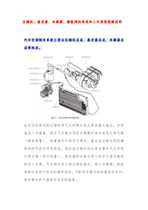
压缩机、蒸发器、冷凝器、膨胀阀的构造和工作原理图解说明

压缩机、蒸发器、冷凝器、膨胀阀的构造和工作原理图解说明汽车空调制冷系统主要由压缩机总成、蒸发器总成、冷凝器总成等构成。
由发动机驱动的压缩机将气态的制冷剂从蒸发器中抽出,并将其压入冷凝器。
高压气态制冷剂经冷凝器时液化而进行热交换(释放热量),热量被车外的空气带走。
高压液态制冷剂经膨胀阀的节流作用而降压,低压液态制冷剂在蒸发器中气化而进行热交换(吸收热量),蒸发器附近被冷却了的空气通过鼓风机吹入车厢。
气态制冷剂又被压缩机抽走,泵入冷凝器,如此使制冷剂进行封闭的循环流动,不断将车厢内的热量排到车外,使车厢内的气温降至适宜的温度。
1压缩机的作用及工作原理1.作用压缩机是汽车空调制冷系统的“心脏”,其作用是维持制冷剂在制冷系统中的循环,吸入来自蒸发器的低温低压制冷剂蒸气,压缩制冷剂蒸气使其压力和温度升高,并将制冷剂蒸气送往冷凝器。
2.工作原理(1)定排量压缩机定排量压缩机的排气量随着发动机转速的提高而成比例提高,它不能根据制冷的需求而自动改变功率输出,而且对发动机油耗的影响比较大。
它的控制一般通过采集蒸发器出风口的温度信号,当温度达到设定的温度时,压缩机电磁离合器松开,压缩机停止工作;当温度升高后,电磁离合器结合,压缩机开始工作。
定排量压缩机也受空调系统压力的控制,当管路内压力过高时,压缩机停止工作。
(2)变排量压缩机变排量压缩机可以根据设定的温度自动调节功率输出。
空调控制系统不采集蒸发器出风口的温度信号,而是根据空调管路内压力的变化信号控制压缩机的压缩比来自动调节出风口温度。
在制冷的全过程中,压缩机始终是工作的,制冷强度的调节完全依赖装在压缩机内部的压力调节阀来控制。
当空调管路内高压端的压力过高时,压力调节阀缩短压缩机内活塞行程以减小压缩比,这样就会降低制冷强度;当高压端压力下降到一定程度,低压端压力上升到一定程度时,压力调节阀则增大活塞行程以提高制冷强度。
2蒸发器的作用及工作原理1.作用蒸发器的作用是将从膨胀阀出来的低压制冷剂蒸发而吸收车内空气的热量,从而达到车内降温的目的。
压缩机结构图汇总

2 1
3 2
三级压缩 -3
三级三列双作用 W 型 1
1
3 3
2 2
三级三列二三级正级差 W 型 - 中间平衡腔
1 1 3
3
2 2
三级两列二三级倒级差立式 2
1
2
1
3
三级三列二三级正级差 W 型 1
1
3 2
3 2
三级三列二三级倒级差 W 型 - 中间平衡腔 1 1
2 3
2 3
三级四列二三级倒级差卧式 - 中间平衡腔
四级四列三四级正级差卧式 - 轴侧平衡腔
3
4
1
2
2
43
34
四级三列三四级正级差 W 型 1
1
2 2
4 3
四级三列倒级差 W 型 1
2
3 4
3 4
四级三列正级差 W 型 2
1
4 3
4 3
四级两列正级差立式 - 中间平衡
2
腔41源自3四级两列正级差立式 - 轴侧平衡
2
腔
4
1
3
四级压缩 -2
四级两列正级差立式
腔
1
1
2
2
两级压缩 -2
两级两列双作用 V 型
两级两列双作用卧式
1 1
2 2
两级两列倒级差 V 型
11
22
两级两列倒级差卧式
1 2
1 2
两级两列正级差 V 型
12
21
两级两列正级差卧式
2 1
2 1
21
12
两级两列倒级差 V 型 - 中间平衡腔
两级两列倒级差卧式 - 中间平衡腔
1 2
1
1
螺杆式压缩机组系统图文详解(经典之作)

螺杆式压缩机组系统图文详解(经典之作)螺杆式压缩机组介绍滑动轴承运行条件(请见南社轴承百科)①油压:高于排气压力1.5~3bar;②油温:35~55℃;③品质:滤网的清洗、润滑油定期更换;④制冷剂含量:减少回液现象。
推力轴承采用NSK的P级轴承,使用的是树脂保持架材料;同时带来压缩机的振动、噪音指标的改善。
轴承内外圈采用优质钢材,无工作应力;针对制冷行业特殊设计,降低异物进入滚道,特殊滚道处理表面使润滑油存油面积大。
轴封采用约翰克兰公司生产的轴封,耐高温、耐工质腐蚀,寿命长。
同时在内部采用密封,使轴封腔与压缩机气腔分离,将腔内压力保持不变,防止工质沸腾,改善轴封封油效果。
“O”型环采用特殊材质不与氨、氟发生反应。
能量调节装置组成:滑阀、油缸、油活塞、滑阀导杆、螺旋导管、喷油导杆、压缩弹簧、能量指示器、四通电磁阀及油管等。
原理:通过滑伐的移动使压缩机阴、阳螺杆齿间工作容积,在齿面接触线从吸气端向排气端移动的前一段内,仍与吸气孔口相通,并使这部分气体回流到吸气孔口。
即减少了螺杆的有效工作长度,来达到能量调节的目的。
滑阀的移动改变螺杆的有效工作长度能量调节失灵的原因1、四通电磁阀故障。
电磁阀的常见故障有阀芯卡住、线圈烧、密封圈失效等。
若阀芯卡住,可用手推动电磁阀两端应急按钮,或对电磁阀阀芯进行拆洗。
2、油管堵塞。
疏通清洗油管。
3、油活塞间隙过大、密封圈老化,造成上、卸载腔不能完全封闭,引起自动上载。
检查更换油活塞密封圈。
4、油活塞卡住。
由于润滑油内含有机械杂质,造成油活塞与油缸拉毛,油活塞卡住。
对油活塞和油缸进行修理。
5、滑阀拉毛卡住。
对滑阀进行修理。
6、油压低,能量调节动力不足,调整油压。
7、能量指示器故障,如指针松动脱落等。
8、能量指示器接线错误。
手动调节按增载按扭,高压油由电磁阀进油接头进入,然后从电磁阀增载接头流出进入油活塞后腔,此时油活塞前腔与电磁阀减载接头相通,并通过电磁阀回油接头与吸气端座上的回油接头相通,那么油活塞后腔压力大于前腔压力,在压差的作用下,油活塞向前腔运动,通过滑阀导管带动滑阀后移。
压缩机课件(往复式压缩机)

往复式压缩机主要零部件
连杆
连杆体材料: 45#锻件; 合金钢锻件; 球铁 连杆螺栓材料: 优质合金钢40Cr, 35CrMoA 小头瓦材料: 铜合金;钢浇巴氏合金 大头瓦: 与主轴承相同
往复式压缩机主要零部件
十字头是连接作摇摆运动的连杆与作往复运动的活塞杆的构件,具 有导向作用。连杆力,活塞力、侧向力在此交汇。
1
2
v
往复式压的压力范围十分有限,当需 要更高压力的场合时,显然,这样高的压力不可能 用单级实现,必须采用多级压缩。 多级压缩:将气体分在若干级中进行逐级压缩, 并在级与级之间将气体进行冷却。
往复式压缩机原理
多级压缩的理由/优势
1. 可以节省压缩气体的指示功。 下图为两级压缩与单级压缩所耗功之比。当第一级压缩达到压力P2 后,将气体引入中间冷却器中冷却,使气体冷却到原始温度T1.因此使 排出的气体容积由V2减至V2’,然后进入第二级压缩到最终压力。这样, 从图中可以看出,实行两级压缩后,与一级压缩相比节省了图中绿色区 域的功。 采用多级压缩可以节省功的主要原因是进行中间冷却。如果没有中 间冷却,第一级排出的气体容积不是因冷却而由V2减至V2’,而仍然以 V2的容积进行二级压缩,则所消耗的功与单级压缩相同。
入口缓冲罐 入口过滤器
出口缓冲罐
冷却器
分 离 罐
往复式压缩机主要零部件
活塞压缩机中,在零件相互滑动的部件,如活塞环与气缸、填料与 活塞杆、主轴承、连杆大头瓦、连接小头衬套以及十字头滑道等处,要 注入润滑剂进行润滑,以达到如下目的: 减小摩擦功率,降低压缩机功率消耗; 减少滑动部位的磨损,延长零件寿命; 润滑剂有冷却作用,可导致摩擦热,使零件工作温度过高,从而保 证滑动部位必要的运转间隙,防止滑动部位咬死或烧伤; 用油作润滑剂时,还有防止零件生锈的作用。
压缩机结构、原理ppt课件

RDS压缩机主机结构
机体特点之四 十字头滑道在 机体内部,充分保 证滑道中心与主轴 承孔中心共面且垂 直。在滑道处开有 适当大的窗口,方 便十字头的安装和 拆卸。
RDS压缩机主机结构
机体特点之五 机体内部埋铸了一 根钢管,作润滑油的主 油道之用。在每个主轴 承座的下面钻有油孔与 主油道相通,主轴瓦上 也设有油孔和油槽。来 自主油泵的润滑油首先 经主油道进入机体油孔 再穿过主轴瓦的油孔, 由油槽在油压的作用下 分布到整个瓦上,润滑 主轴瓦和曲轴主轴颈。
RDS压缩机主机结构
机体特点之一 主轴承孔为剖分式 为保证精度,主轴承盖 与机体配对加而成,并 作有配对标记。组装时 不得将这个座上的主轴 承盖装在另一个座上, 也不得将其旋转180°安 装。
RDS压缩机主机结构
机体特点之二 主轴承座与主轴承盖 之间装有可调整厚度的垫 片,该垫片由多个薄片叠 加而成,减少几层薄片以 将垫片降低至适当的厚度 ,从而使主轴瓦与曲轴间 具有合适的间隙 。使用时 注意,该垫片只能从厚至 薄,不可将薄垫片垫厚使 用。
RDS压缩机主机结构
余隙塞:在余 隙调节范围内, 改变余隙活塞的 位置可调节余隙 容积。
RDS压缩机主机结构
RDS压缩机主机结构
排气量 104Nm3/d
22 21 20 19 18 17 16 15 14 13 12
0
5
10
排气压力1.2MPa,进温30 排气压力1.2MPa,进温40
15
20
RDS压缩机主机结构
RDS压缩机主机结构
气阀: 气阀在压
缩机的进、排 气通道上起单 向阀的作用。
RDS压缩机主机结构
主油泵: 主油泵装在机体
内,由曲轴端部的拨 销驱动。
往复式压缩机结构介绍及维护ppt课件

24
b、如图,从中心连接螺栓处观察,有弹簧孔的为排气阀,无弹 簧孔的则为进气阀
25
3.2 活塞环、支撑环 活塞环的定义:活塞环是密封汽缸工作面和活塞间缝
隙的零件,对有油润滑的气缸而言,活塞环同时还起着润滑 油的分布和导热作用。
活塞环的工作原理:活塞环装入气缸后,如下图,活塞 环的弹力使之产生一个对汽缸壁 的压紧力。气体通过间隙产生节 流,于是在活塞环前后产生一个 压差,活塞环被推向环槽压力低 的一侧,阻止了气体沿环槽端面 的泄漏。作用在环内表面的气体 压力大于环外表的气体压力,在 压力差的作用下,环被压向汽缸 工作表面,阻止了气体沿汽缸壁 的泄漏。
23
c、装入阀座,拧紧气阀中心连接螺母(有力矩要求)。 d、气阀组装后,阀片、弹簧运动时应无卡住和歪斜现象;气
阀开启高度符合规定,一般为2.2~2.6mm。 e、气阀组装好后应用煤油做气密性试验,在5min内允许有滴
状渗漏。 3.1.5 进排气阀的判断 a. 如图,从中心连接螺栓方向试验,阀片能顶动则为进气阀,
8
二、活塞式压缩机基本构件-主轴承
2.3 主轴承 主轴承是两片轴瓦组成,轴瓦
是铝基且表面上镀有一微层巴氏合 金结构。两片轴瓦准确地置于剖分 线两侧,并且在轴瓦上钻孔装上定 位销以确保组件上准确的方位。在 轴瓦间使用叠层垫片以便进行垂直 方向间隙调整。垫片由厚度0.003in (0.08mm)的可剥离的薄片叠合而 成,然后压合在钢垫板上。
29
透光试验及活塞环接口间隙测量
30
3.3 填料函及填料 通常,所有的活塞杆都采用悬浮式密封。密封组件有两
个基本零件-密封室和密封圈。密封室由若干填料盒(它里 面是密封圈)和一个有四根固定螺栓的钢制法兰组成。这些 填料盒用至少两根螺栓连起来。标准的密封组件采用水冷, 这样在填料盒之间需要装O形环来密封水通道。
- 1、下载文档前请自行甄别文档内容的完整性,平台不提供额外的编辑、内容补充、找答案等附加服务。
- 2、"仅部分预览"的文档,不可在线预览部分如存在完整性等问题,可反馈申请退款(可完整预览的文档不适用该条件!)。
- 3、如文档侵犯您的权益,请联系客服反馈,我们会尽快为您处理(人工客服工作时间:9:00-18:30)。
B B
Ring as assembled on rod
AA
B
Pressure Side
“BT” Packing Ring单作用环
Ring as assembled on rod
Ring as assembled on rod
Double Acting Rings Either Side May Face Pressure
2nd Stage Cylinder
Section No. 2
Section No. 3
End Section
ORing
Inlet Section
Section No. 1
2nd Stage Cylinder
Section No. 2
Section No. 3
End Section
ORing
Inlet Section
ORing
Inlet Section
2nd Stage Packing
Section No. 1
Section No. 2
Section No. 3
End Section
ORing
Inlet Section
2nd Stage Packing
Section No. 1
Section No. 2
Section No. 3
Section No. 3
End Section
1st Stage Cylinder
ORing
Removing air from the lubricator line.
单流阀
盘根
填料环
A
(Ring as assembled on rod)
Total opening at one cut only = Rod Dia. x .010”
Valve Losses
Valve Losses
Volume
Pressure
原理
PV/T=定量
等熵绝热过程 在一定的温度下,体积增大,
压力减小;反之亦然。
P2
P2线代表排出压力
PRESSURE
P1线代表吸入压力 P1
.
VOLUME
P2
P2线代表排出压力
P1线代表吸入压力 P1
PRESSURE
VOLUME
Section No. 2
Section No. 3
End Section
1st Stage Packing
ORing
Inlet Section
Section No. 1
Section No. 2
Section No. 3
End Section
1st Stage Packing
ORing
Inlet Section
ORing
Inlet Section
Section No. 1
Section No. 2
Section No. 3
End Section
1st Stage Cylinder
ORing
Inlet Section
Section No. 1
Section No. 2
Section No. 3
End Section
MAXIMUM CYLINDER VOLUME
CRANK END
INBOARD DEAD CENTER
Typical Single Acting P-V Diagram
USEFUL WORK
LOSS DUE TO DISCHARGE VALVE
LOSS DUE TO SUCTION VALVE
Typical Double Acting PV Diagram
“BD” Packing Ring双作用环
Seal Rings Required in a Packing Case
• 2000 (Biblioteka ) psi ……………….5-7 rings
• 800-2000…………………..4-6 rings • 300-800……………………3-5 rings • below 300…………….……2-4 rings
十字头
十字头销拆除
十字头销拆除
十字头拆除
连杆拆除
分配器
过滤器
注油泵3/8″
注油系统
无油流开关 爆破片
典型注油泵工作过程
无油流开关
DNFT-PRG
分配器
SMX Metering Element Chart
Metering Element Size
SMX-08
Delivery In3 (Twin)
Section No. 2
Section No. 3
End Section
1st Stage Cylinder
ORing
Inlet Section
Section No. 1
Section No. 2
Section No. 3
End Section
1st Stage Cylinder
ORing
Inlet Section
1st Stage Cylinder
ORing
Inlet Section
Section No. 1
Section No. 2
Section No. 3
End Section
1st Stage Cylinder
ORing
Inlet Section
Section No. 1
Section No. 2
.005
Delivery In3 (Single)
.010
Element Part Number
641516
SMX-12
.0075
.015
641790
SMX-16
.010
.020
641517
SMX-25
.015
.030
641518
SMX-35
.020
.040
641519
SMX-40
.025
.050
641520
刮油环
Correct Orientation of Wiper Rings
活塞环
Piston Ring
One Piece But Cut
Two Piece Angle Cut
One Piece Angle Cut
Three Piece Step Cut
Cylinder bore
Counterbore
P2
P2线代表排出压力
P1线代表吸入压力 P1
PRESSURE
VOLUME
排气阀开启
P2
P2线代表排出压力
P1线代表吸入压力 P1
PRESSURE
VOLUME
P2线代表排出压力 P2 P1线代表吸入压力 P1
PRESSURE
VOLUME
P2
P2线代表排出压力
P1线代表吸入压力 P1
PRESSURE
Typical Configuration
连杆通过大 头瓦与曲轴
相连
压缩机剖面动态图
刮油盘根
盘根注油
活塞杆 盘根
进气阀
曲轴箱
连杆通过小 头瓦与十字
头相连
活塞杆
排气阀
DISCHARGE VALVE CLOSES
DISCHARGE VOLUME
DISCHARGE VALVE OPENS
PRESSURE
Section No. 2
Section No. 3
End Section
ORing
Inlet Section
Section No. 1
2nd Stage Cylinder
Section No. 2
Section No. 3
End Section
ORing
Inlet Section
Section No. 1
Section No. 1
Section No. 2
Section No. 3
End Section
1st Stage Cylinder
ORing
Inlet Section
Section No. 1
Section No. 2
Section No. 3
End Section
1st Stage Cylinder
Section No. 3
End Section
ORing
Inlet Section
2nd Stage Packing
Section No. 1
Section No. 2
Section No. 3
End Section
ORing
Inlet Section
Section No. 1
2nd Stage Cylinder
Seal
= gas pressure
Piston movement
Piston
Seal
支撑环
Rider Ring / Band
Using rider rings or rider bands to support the piston off of the bore
Section No. 3
End Section
ORing
2nd Stage Cylinder
Inlet Section
Section No. 1
Section No. 2
Section No. 3
End Section
ORing
2nd Stage Cylinder
Inlet Section
