Kontronik PROGCARD II ESC K牌电调设置卡 编程卡说明书 K9306
航模无刷电机调速器说明书
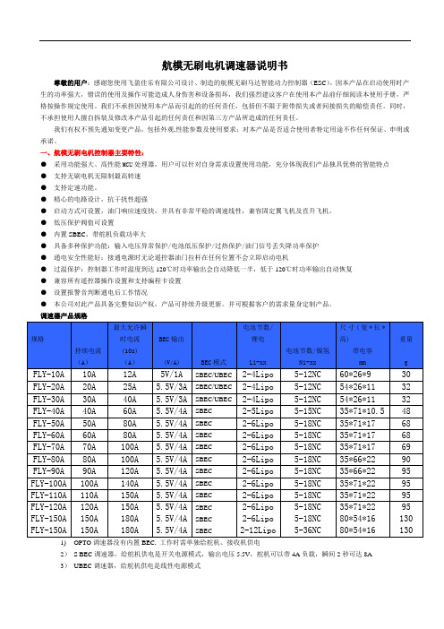
航模无刷电机调速器说明书尊敬的用户:感谢您使用飞盈佳乐有限公司设计、制造的航模无刷马达智能动力控制器(ESC)。
因本产品在启动使用时产生的功率强大,错误的使用及操作可能造成人身伤害和设备损坏,我们强烈建议客户在使用本产品前仔细阅读本使用手册,严格按操作规定使用。
我们不承担因使用本产品而引起的的任何责任,包括但不限于附带损失或者间接损失的赔偿责任。
同时,不承担使用人擅自拆装及修改本产品引起的任何责任和因第三方产品所造成的任何责任。
我们有权不预先通知变更产品,包括外观,性能参数及使用要求;对本产品是否适合使用者特定用途不作任何保证、申明或承诺。
一、航模无刷电机控制器主要特性:●采用功能强大、高性能MCU处理器,用户可以针对自身需求设置使用功能,充分体现我们产品独具优势的智能特点●支持无刷电机无限制最高转速●支持定速功能。
●精心的电路设计,抗干扰性超强●启动方式可设置,油门响应速度快,并具有非常平稳的调速线性,兼容固定翼飞机及直升飞机。
●低压保护阀值可设置●内置SBEC,带舵机负载功率大●具备多种保护功能:输入电压异常保护/电池低压保护/过热保护/油门信号丢失降功率保护●通电安全性能好:接通电源时无论遥控器油门拉杆在任何位置不会立即启动电机●过温保护:控制器工作时温度到达120℃时功率输出会自动降低一半,低于120℃时功率输出自动恢复●兼容所有遥控器操作设置和支持编程卡设置●设置报警音判断通电后工作情况●本公司对此产品具备完整知识产权,产品可持续升级更新。
并可根据客户的需求量身定制产品。
调速器产品规格1)OPTO调速器没有内置BEC, 工作时需单独给舵机、接收机供电2)S BEC调速器,给舵机供电是开关电源模式,输出电压5.5V,舵机可以带4A负载,瞬间2秒可达8A3)UBEC调速器,给舵机供电是线性电源模式三、调速器连接线说明:(为避免短路和漏电,连接处均使用热缩导管绝缘)一、航模无刷电机调速器功能:1.出厂默认恢复设置2.电池类型(LiPo或NiMh/NiCd)设置3.刹车设置(有/无)4.低压保护阈值设置(设置高低电压保护值)5.马达进角设置(提高电调使用效率和调速的平稳性)6.加速启动设置(针对精密变速箱和直升机应用)7.直升机模式(针对直升机应用)8.马达转向(顺时针/逆时针)9.PWM工作频率设置10.低压保护模式(降低功率或立即停止)四、无刷电机电子调速器编程设置操作步骤:先将遥控器油门拉杆推至最高位置,电调进入设置模式,然后打开遥控器电源。
mk电调说明书
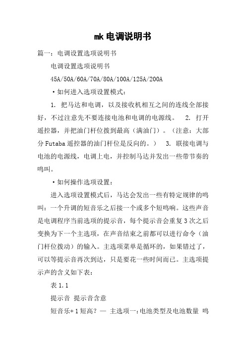
mk电调说明书篇一:电调设置选项说明书电调设置选项说明书45A/50A/60A/70A/80A/100A/125A/200A·如何进入选项设置模式:1. 把马达和电调,以及接收机相互之间的连线全部接好,不过注意先不要连接电池和电调的电源线。
2. 打开遥控器,并把油门杆位拨到最高(满油门)。
(注意:大部分Futaba遥控器的油门杆位是反向的。
)3. 联接电调与电池的电源线,电调上电,并控制马达并发出一些带节奏的鸣叫。
·如何操作选项设置:进入选项设置模式后,马达会发出一些有特定规律的鸣叫:一个升调的短音乐之后接一个或多个短鸣响。
这些声音是电调程序当前选项的提示音,每个提示音会重复3次之后变换为下一个主选项,在声音结束之前都可以进行命令(油门杆位拨动)的输入。
主选项菜单是循环的,如果错过了,可以等提示音再次到达,只是要花一些时间而已。
主选项提示声的含义如下表:表1.1提示音提示音含意短音乐+ 1短高?—主选项一:电池类型及电池数量鸣短音乐+ 2短高?——主选项二:油门相关设置鸣主选项三:刹车(标准固定翼版短音乐+ 3短高?———本电调)鸣 /操作模式(电直版本电调)短音乐+ 4短高?————主选项四:方向及保护模式鸣?————短音乐+ 5短高主选项五:PWM设置—鸣第一步,选择主选项并进入子选项菜单。
如表1.1,当听到需要设置的主选项提示音出现时,因为提示音是重复3次的,建议第一次听到则留意,第二次听到则复核并进行选择操作:拨动油门杆位到中间位置,此表示选择当前主选项并进入子选项菜单。
因为已经进入第二层菜单,现在马达发出的声音会有一些变化以区别主选项菜单,升调短音乐改为短高鸣提示当前为第几主选项,主选项的短高鸣改为长低鸣提示当前为第几子选项(提示主选项的一个或多个短高鸣+提示子选项的一个或多个长低鸣)。
详细含义可以查第二页和第三页的子选项列表。
每个子选项提示音也是重复3次然后变成下一子选项并循环。
HiModel COOL系列电调用户手册说明书

Thank you for purchasing our products! For the high power of this brushless system, failure to use may result in injury yourself and damage of the whole device. So we highly recommend you to read carefully and abide by the operating procedures of this manual before the first flight. SunRise is not responsible for your misuse of this product or any damage including incidental losses or indirect losses you may cause. Moreover, we have not any responsibility for the modification of our products without authorization. We have the right to change the design, features, functions and operating requirements of our products without any advanced notice!IMPORTANT PRECAUTIONS:● Read the manual correctly before your operating.● Do not connect oppositely the polarity between the battery pack and the Electronic Speed Controller(for short ESC). Wrong connecting of polarity will damage the ESC.● The working range of ESC should not exceed the corresponding voltage and current.● Do not disassemble any electronic components of ESC, or else it will cause permanent damage or information losses.● Do not allow any unqualified battery pack.● Do not connect a degaussed motors.● Do not use any substandard cable connector.● Do not allow chemical agent and water onto the ESC.● Do not take the battery away when the motor is rotating, or else it may cause high burst current to damage the ESC.● The ESC should be in a position which allows good airflow and heat dissipation.● Always disconnect the battery from the ESC when not in use.Features:●Super fine and smooth touch of speed controlling, first-rate accurate linearity and quick-respond speed of throttle.●With High Performance CPU of 24MHZ, Separate voltage regulator IC for MCU (Micro Controller Unit), high capability of anti-interference to decrease the possibility out of control.●Low-voltage cut-off protection of battery, blocked rotation protection and throttle signal lose protection, etc. All these functions can prolong the service life of ESC effectively.●Good and safe performance of power-on. The motor won’t be started no matter which position the throttle stick is on when the battery is connected.●Low torque "soft start," protecting gear box●LED status indicator (LED keep shine under full throttle)●Easy Installation, can change motor rotation direction by Prog-card●Compatible for fixed wing airplane and helicopter; perfect governor mode for helicopter●BEC circuit,SBEC output 6A●With new generation MOSFET, lower internal resistance, stronger resistance to impulse current ●MOSFET in independent PCB, the thickness of copper plate reaches 800μm, the thickness of high current ESC copper plate reaches 1200μm). Super low impedance and strongest resistance to high current which could effectively reduce the temperature rise, improve the quality and make the ESC work at optimal efficiency●It can be compatible with a programming card (optional component), which has a simple and visual surface so as to change the parameters conveniently at any time anywhere (reference to the manual for programming card).Page 1 Connection:Use a good quality battery plug to connect cable, make sure right polarity.Connect the 3 cables of ESC to motor. If the motor rotation direction is wrong, please exchange connection for any 2 of the 3 cables, or use programming card to change the direction.Plug the JR connector into the throttle control channel of the receiver. (HV ESC needs a separate BEC or battery to supply power for the receiver).Switch “on” the transmitter and move the stick of throttle to the lowest position. Only at the lowest position, can the ESC work and will have buzzing sound to confirm working.Connect the main power pack to ESC (pay attention to the polarity). There are different beep sounds to recognize the cells of battery (2 beeps for 2 cells battery, 3 beeps for 3 cells battery, and so on ). Please make sure that every battery is with full power, or the ESC may mistakenly recognize the cells of battery.Enter into Programming by transmitter:Connect ESC to motor, switch on transmitter, move the stick of throttle to the highest position (including throttle fine adjustment)2.Connect ESC to the power, there will be a short tone.3.Move the stick of throttle to the middle position, there will be another short tone.4.Move the stick of throttle to the highest position, there will be repeated short tones, then move again the stick of throttle to the middle position to make repeated tones, ESC enter into programming mode. Successfully enter into the first setting (voltage option) .5. You should only answer YES or NO for setting. If answer NO, none of any setting would be stored but enter into the next setting. If answer YES, the setting would be stored and go to the next setting.6. The stick of throttle must be in the middle position to answer options. If answer NO, please move the stick of throttle to lowest position and hold for 2 seconds. When ESC receives your answer, LED will fast twinkle and send out Beep sound. If answer YES, please move the stick of throttle to highest position and hold for 2 seconds. When ESC receives your answer, LED will fast twinkle and send out Beep sound. When LED fast twinkle, please move the stick of throttle to middle position to confirm ready for next option.7. If you don’t want to answer all options, you could disconnect the power from ESC after you set the parameters you need.Page 2Following with * are Factory Default SettingsProgramming Setting 1: Cut-off Voltage*Option 1: Auto-Lipo Option 2: 4.0V cut-off Option 3: 5.0V cut-off Option 4: 6.0V cut-off Option 5: 9.0V cut-off Option 6: 12 V cut-offAcousto-optic Indicator Question Answer YES- move the stick of throttle to highest position. Enter to next settingTwinkle (Bi)1 time-short pause -Twinkle (Bi)1 time-long pauseSetting 1(cut-off voltage ) Option 1 (Auto-Lipo )NO- move the stick of throttle to lowest position. Enter to next settingYES- move the stick of throttle to highest position. Enter to next settingTwinkle (Bi) 1 time-short pause-Twinkle (Bi)2 times-long pauseSetting 1(cut-off voltage ) Option 2 (4.0V ) NO- move the stick of throttle to lowest position. Enter to next settingYES- move the stick of throttle to highest position. Enter to next settingTwinkle (Bi) 1 time-short pause-Twinkle (Bi)3 times-long pauseSetting 1(cut-off voltage ) Option 3 (5.0V ) NO- move the stick of throttle to lowest position. Enter to next settingYES- move the stick of throttle to highest position. Enter to next settingTwinkle (Bi) 1 time-short pause-Twinkle (Bi)4 times-long pauseSetting 1(cut-off voltage ) Option 4 (6.0V ) NO- move the stick of throttle to lowest position. Enter to next settingYES- move the stick of throttle to highest position. Enter to next settingTwinkle (Bi) 1 time-short pause-Twinkle (Bi)5 times-long pauseSetting 1(cut-off voltage ) Option 5 (9.0V ) NO- move the stick of throttle to lowest position. Enter to next settingYES- move the stick of throttle to highest position. Enter to next settingTwinkle (Bi) 1 time-short pause-Twinkle (Bi)6 times-long pauseSetting 1(cut-off voltage ) Option 6 (12.0V ) NO- move the stick of throttle to lowest position. Enter to next settingProgramming Setting 2: Reservation (for future use)Programming Setting 3: Brake Type4 seconds can be delayed before brake. Soft Brake is 50% of full brake, Hard Brake is 100% of full brake.* Option 1:Soft brake 、delayed: for airplane with fixed paddle or folded paddle Option 2:Hard brake 、delayed: for direct drive needs hard brake Option 3:Soft brake, no delay: in the race, request very short delayOption 4:Hard brake, no delay: in the race, request fast brake with very short delayPage 3Option 5:No brake: for helicopterAcousto-optic Indicator Question AnswerYES- move the stick of throttle to highest position. Enter to next settingTwinkle (Bi)3 times-short pause -Twinkle (Bi)1 time-long pauseSetting 3(Brake Type )Option 1 (Soft brake 、4s delayed)NO- move the stick of throttle to lowest position. Enter to next settingYES- move the stick of throttle to highest position. Enter to next settingTwinkle (Bi)3 times-short pause -Twinkle (Bi)2 times-long pauseSetting 3(Brake Type )Option 2 (Hard brake 、4s delayed)NO- move the stick of throttle to lowest position. Enter to next settingYES- move the stick of throttle to highest position. Enter to next settingTwinkle (Bi)3 times-short pause -Twinkle (Bi)3 times-long pauseSetting 3(Brake Type )Option 3 (Soft brake 、no delay)NO- move the stick of throttle to lowest position. Enter to next settingYES- move the stick of throttle to highest position. Enter to next settingTwinkle (Bi)3 times-short pause -Twinkle (Bi)4 times-long pauseSetting 3(Brake Type )Option 4 (Hard brake 、no delay)NO- move the stick of throttle to lowest position. Enter to next settingYES- move the stick of throttle to highest position. Enter to next settingTwinkle (Bi)3 times-short pause -Twinkle (Bi)5 times-long pauseSetting 3(Brake Type ) Option 45(No brake)NO- move the stick of throttle to lowest position. Enter to next settingPage 4Programming Setting 4: Throttle Type* Option 1:Auto throttle: recommendedOption 2:Fixed throttle: for fixed pitch helicopterOption 3:Governor mode, low RPM (see notes): for collective pitch helicopter (brake keep shuttingin Governor mode)Option 4:Governor mode, high RPM (see note): for collective pitch helicopter (brake keep shuttingin Governor mode)Acousto-optic Indicator Question AnswerYES- move the stick of throttle to highest position. Enter to next settingTwinkle (Bi)4 times-short pause -Twinkle (Bi)1 time-long pauseSetting 4(Throttle Type ) Option 1 (Auto throttle) NO- move the stick of throttle to lowest position. Enter to next settingYES- move the stick of throttle to highest position. Enter to next settingTwinkle (Bi)4 times-short pause -Twinkle (Bi)2 times-long pauseSetting 4(Throttle Type ) Option 2 (Fixed throttle) NO- move the stick of throttle to lowest position. Enter to next settingYES- move the stick of throttle to highest position. Enter to next settingTwinkle (Bi)4 times-short pause -Twinkle (Bi)3 times-long pauseSetting 4(Throttle Type ) Option 3 (Governor mode, low RPM) NO- move the stick of throttle to lowest position. Enter to next settingYES- move the stick of throttle to highest position. Enter to next settingTwinkle (Bi)4 times-short pause -Twinkle (Bi)4 times-long pauseSetting 4(Throttle Type ) Option 4 (Governor mode, high RPM)NO- move the stick of throttle to lowest position. Enter to next settingNote :Governor mode acts as an RPM control, not a throttle control. Throttle stick position determines the RPM that the motor will run and the controller will attempt to hold that RPM regardless of how the load (collective) changes.The low RPM range has finer RPM control at lower RPMs. The high RPM range has finer RPM control at higher RPMs.The low RPM range is useful for low pole count motors (Hacker etc.) and low RPMs on higher pole count motors. The high RPM range is useful for higher pole count motors and higher RPMs. Brake is usually been used under governor mode.Page 5Programming Setting 5: TimingOption 1:High timing, improve the rotation speed, consume more current, increase heat in working * Option 2:Standard timing, reach at good balance between power and efficiencyOption 3:Low timing, select this option when considering efficiency and flying time as first choice, lesspower consumption, better efficiencyAcousto-optic Indicator Question Answer YES- move the stick of throttle to highest position. Enter to next settingTwinkle (Bi) 5 times-short pause -Twinkle (Bi) 1 time-long pauseSetting 5(Timing ) Option 1 (High timing) NO- move the stick of throttle to lowest position. Enter to next setting YES- move the stick of throttle to highest position. Enter to next settingTwinkle (Bi) 5 times-short pause -Twinkle (Bi) 2 times-long pauseSetting 5(Timing ) Option 2 (Standard timing) NO- move the stick of throttle to lowest position. Enter to next setting YES- move the stick of throttle to highest position. Enter to next settingTwinkle (Bi) 5 times-short pause -Twinkle (Bi) 3 times-long pauseSetting 5(Timing ) Option 3 (Low timing) NO- move the stick of throttle to lowest position. Enter to next settingProgramming Setting 6: Cut-off Type* Option 1:Hard Cut-off (Motor shut off instantly at low voltage) Option 2:Soft Cut-off (Throttle reduces at low voltage)Acousto-optic Indicator Question Answer YES- move the stick of throttle to highest position. Enter to next settingTwinkle (Bi) 6 times-short pause-Twinkle (Bi) 1 time-long pauseSetting 6(Cut-off Type ) Option 1 (Hard Cut-off) NO- move the stick of throttle to lowest position. Enter to next settingYES- move the stick of throttle to highest position. Enter to next settingTwinkle (Bi) 6 times-short pause-Twinkle (Bi) 2 times-long pauseSetting 6(Cut-off Type ) Option 2 (Soft Cut-off) NO- move the stick of throttle to lowest position. Enter to next settingPage 6Programming Setting 7: Soft Start-upOption 1:Very soft start-up: for fragile gear box; or very slow and very soft start-up in governormode, very slow rotor* Option 2:Soft start-up: recommend for most settings, soft start-up, slow rotorOption 3:Fast start-up: for very fast start-up, the fastest start-up under Governor mode, fast rotorAcousto-optic Indicator Question Answer YES- move the stick of throttle to highest position. Enter to next setting Twinkle (Bi)7 times-short pause -Twinkle (Bi)1 time-long pauseSetting 7(Soft Start-up ) Option 1 (Very soft start-up) NO- move the stick of throttle to lowest position. Enter to next settingYES- move the stick of throttle to highest position. Enter to next setting Twinkle (Bi)7 times-short pause -Twinkle (Bi)2 times-long pauseSetting 7(Soft Start-up ) Option 2 (Soft start-up) NO- move the stick of throttle to lowestposition. Enter to next settingYES- move the stick of throttle to highest position. Enter to next setting Twinkle (Bi)7 times-short pause -Twinkle (Bi)3 times-long pauseSetting 7(Soft Start-up ) Option 3 (Fast start-up) NO- move the stick of throttle to lowestposition. Enter to next settingProgramming Setting 8: PWM Adjustment (No this function for ESC below 44A)Option 1:12KHz ,recommend for most brushless motor Option 2:16KHz ,recommend for low sensing motorOption 3:24KHz ,recommend for very low sensing motor*Option 4:Outrunner motor mode, recommend for all kinds of outrunner motorsPage 7Acousto-optic Indicator Question AnswerYES- move the stick of throttle to highest position. Finish setting. Twinkle (Bi)8 times-short pause -Twinkle (Bi) 1 time-long pauseSetting 8(PWM )Option 1 (12KHz)NO- move the stick of throttle to lowest position. Finish setting.YES- move the stick of throttle to highestposition. Finish setting. Twinkle (Bi)8 times-short pause -Twinkle (Bi) 2 times-long pause Setting 8(PWM )Option 2 (16KHz)NO- move the stick of throttle to lowest position. Finish setting.YES- move the stick of throttle to highestposition. Finish setting. Twinkle (Bi)8 times-short pause -Twinkle (Bi) 3 times-long pause Setting 8(PWM )Option 3 (24KHz)NO- move the stick of throttle to lowest position. Finish setting.YES- move the stick of throttle to highestposition. Finish setting.Twinkle (Bi)8 times-short pause -Twinkle (Bi) 4 times-long pauseSetting 8(PWM )Option 4 (Outrunner motormode)NO- move the stick of throttle to lowestposition. Finish setting.User Manual for COOL Series Prog-Card IIIThank you for purchasing our products! This Programming Card is especially designed for COOL series brushless ESC, which could help you easily set the parameters of ESC. With it, you don’t have to move the stick of throttle up-and-down with hearing the sounds from ESC to set the parameters. Small and light to bring makes the Prog-Card capable to use outdoors.Operating instructions:-Connect the ESC signal cables to the relevant positions of Prog-card (orange cable-signal, brown cable- negative pole ( -), red cable- positive pole ( +)). - HV (OPTO series ESC ) need extra 4-7V voltage. - Connect ESC power- Longitudinal and latitudinal LED indicators light up to show the present settings of ESC.- Longitudinal LED light up to show the menu options of ESC, while latitudinal LED light up to show the parameter of menu options.- Short gentle press on the switch to change menu options (from up to down), long gentle press on the switch to change the parameter of menu options (from left to right).Notice: There would be no prompting sound when using Prog-card to set parameters if the ESC connected to the motor . LED indicators show the present settings of ESC.Page 8。
K系列电梯调试培训_OK

轿厢在下强迫减速区 同步开关有效
Drive down(黄色) 2021/8给/6变频器下行命令
灭 未给 轿厢不在上减速区 轿厢不在61:U区 轿厢不在门区 轿厢不在B门区 轿厢不在61:N区 轿厢不在下减速区 无效 无效
注释
77:U打开 高于平层20mm/低于平层 75mm 高于平层130mm/低于平层 130mm
submenu2
消除错误内召设为1
1-42
1
内召注册时有蜂鸣
1-71
3
检修驱动在端站停止
1-72
0
锁梯返回层
1-79
0
锁梯时照明关闭设为0,锁梯时照明不关闭设为1
1-83
1
超载闪烁信号
1-92
1 2021/8/6
风扇类型,自动有关闭开关
20
1-93
0
COP不可选择,单开门设0,贯通门设1
1-94
7
到站钟
亮 有报警
阻碍正常操作的错误 CPU运行 42:DS开关在检修位 RDF(紧急电动)开关在 ReCall位 表示LCECPU 板与LCECCB板 通过通信正常 LCECPU 板与楼层板通信正常
给控制器的+24V电压正常
给LCECPU的+5V电压正常
灭 没有报警
操作正常 CPU 不运行 42:DS开关在正常位 RDF(紧急电动)开 关在正常位 表示通信不正常
编辑数字参数时,用来选择参数的位,在数值编辑模式中滚动数字,从报警表 或help模式回到正常模式。按shift键后,离开数值编辑或选择不改变。
进第二入个选功取能或,编是辑从后任的何数主值菜状单态返,回发到布监命控令菜,单在。报警表模式中确认报警。Hom1e5的
选择按键第二功能:(Rotation control,Jog,Help,Alarm,Escape,Home )
Kingkong 系列无刷电子调速器 说明书

Start
end point
第11页
·单击鼠标右键则恢复到数据最初的曲线图. 注:软件总是读取最近一次飞行的数据.
升级调速器固件程序
厂家推出新的固件程序时,用户可直接刷新调速器的固件程序 ·点击功能菜单中的‘Update’; ·单击‘Browse’键浏览并选择新的固件程序; ·点击‘Start’ 开始升级,升级过程将在3~5秒中完成。升级过程中调速器上的绿色LED会持 续闪烁。
(注:电机四声鸣叫后,调速器将进入参数设置程序) 5、 约一秒后,马达发出两声鸣叫,遥控器油门标定设置完成 。 6、 可启动马达进行飞行。
五、 调速器参数
第5页
Kinkong 调速器全可编程参数值:
建议: 请参照下列表格,在使用调速器前根据模型飞机动力系统的配置设置调速器的参数。
锂电池过压保护 自动检测 5.0V (低压调速器)
连接调速器到电脑
第8页
·将调速器的R/C线连接到USB Linker,请参照USB Linker标签上的线色说明正确连接。
·将USB Linker插入电脑上任意一个可用的USB接口,USB Linker上的红色LED灯会亮起来,调 速器上的绿色LED也会恒亮。
注:连接时请将调速器与电池断开。 若USB Linker上的红色LED灯和调速器上的绿色LED灯没亮,说明没连接好,请检查连接是否
第3页
用合适的香蕉插头焊接到调速器的三条红色马达线,分别与无刷马达的三条线连接;(注:调换 调速器的任意两条马达线,可改变马达旋转方向)
使用好质量的插头焊接到调速器的电源线,启动时正确连接到电池的正负极。
1、低压电压请参照下列图①
图①
2、高压电调请参照下列图②
图②
第4页
车用电子调速器ESC说明书

车用无刷电子调速器(ESC)说明书感谢您购买本公司产品,为避免错误的使用造成不必要的损失,请仔细阅读此说明书,并严格按照此说明书进行操作。
我司不承担使用本产品造成损失的任何责任、同时不承担因使用者擅自修改产品而引起的任何责任。
产品特色●多重保护功能:电池低压保护、过温保护、油门失控保护、堵转保护。
●比例式刹车:4段最大刹车力度调节、8段拖刹力度调节、4段初始刹车力度调节。
●可利用电调上的按键实现单键编程设定,且有单键恢复出厂设置的功能。
●支持多种参数编程方式。
产品型号及规格参数型号25A 35A 60A持续电流/峰值电流18A/50A35A/190A60A/380A支持电机类型无感无刷无感无刷无感无刷适用车型1:18电房1:10电房/电越1/10电房和电越内阻0.01欧姆0.0015欧姆0.0007欧姆电池节数2-3节锂电,4-9节镍氢电池2-3节锂电,6-9节镍氢电池2-3节锂电,6-9节镍氢电池BEC输出6V/1A6V/1.5A6V/1.5A尺寸31.5mm(长)*24mm(宽)*15mm(高,减除风扇)31.5mm(长)*27mm(宽)*24mm(高,减除风扇)31.5mm(长)*27mm(宽)*24mm(高,减除风扇)重量19g(不含引线重量)30g(不含引线重量)32g(不含引线重量)使用步骤第一步 根据所使用的电机正确连线。
②接无感无刷电机:当使用无霍尔传感器的无刷电机时,电调输出线A、B、C可和电机线任意相连,若转向不对,任意调换其中两条线即可。
警告:电源正负极不能接反,否则电调立即烧坏,(红线为正极、黑线为负极)。
长时间不使用,请拔下电池,以免造成不必要的意外。
第二步设定油门行程1 电调开关置于OFF 状态,电调接上电池,打开遥控器,将油门通道方向设置为“REV”,油门微调设置为“0”,油门通道的EPA/ATL 正反向均设置为100% (最大)。
请务必关闭遥控器自带的ABS 刹车功能。
电调操作说明

ICE系列ESC操作说明技术参数(ICE 45A- 150A)2-6S LiPo,6-18 NiMH(ICE HV60A,HV100A)4-12s LiPo, 12-36 NiMH(ICE HV120,HV180HV) 4-14s LiPo,5-15s(LiFePO4),12-42 NiMH,- SBEC :5.5V,6A(高压系列无BEC输出)- 低电压保护- 光电耦合器- 定速模式- 软启动- 激活惯性滑行(自动旋转),- 自动进角或者六段进角调节- 持续可调整的F3A的刹车- 3段可调节的电动势刹车- 切换频率:8 to 16 kHz- 速度限制:240,000转(2极马达)- 温度和超载警告- 消火花电路(防打火设计)- 可用于飞机与直升机- 可用编程卡编程初始化接通电源打开遥控器时你将听到三声降调。
然后是与之电池数量相关的蜂鸣声(4S时连续快速响4声,5S 与6S以此类推)。
当连接7至14s的电池会产生两声高音两声低音;之后将会产生三声升调,这时ESC可以开始工作。
如果马达转动方向错误,请仅交换马达三根线的任意两根电线。
速度控制器有固定的油门曲线设置,这样确保所有的遥控器的停止点和全油门点是成线性连接。
所有可编程遥控器,油门范围应设置为默认(± 100%),中心点设置为零和油门微调启用。
然而,有些类型的遥控器油门范围需要进行校正。
关于油门行程一定要设置2个末端点位,一个点位是油门杆在最低的位置时马达是停止的,还有一个点位置是全油门时马达是全功率的,LED指示灯熄灭表示全油门了。
在出厂时进角调节为18°,中等刹车,并且低电压保护值为3.1V的锂电池模式。
如果在加速时出现了叫声或其他的不正常声音,那么进角要加大。
如果进角增加到30°还不能改善,那么你的马达将是超负荷的,,此时使用一个较小的螺旋桨或降低电压,或更换一个性能更好的马达。
如果当马达停止工作时你听到两声重复的蜂鸣声,表示电池的电压已低于设定值。
中特威车用电调CAR ESC中文说明书
中特威科技竞赛级车用无刷电子调速器说明书尊敬的用户:感谢您使用中特威科技有限公司设计、制造的竞赛级车用无刷电子调速器。
ZTW 车模用调速器专门针对竞赛级车模用而开发的有感,无感无刷马达专用电子调速器。
我们强烈建议您在使用之前阅读本使用手册中特威公司有权不经通知变更其产品,包括其外观和性能参数及使用要求;对其产品是否适合特定用途不作任何保证、申明或承诺。
不承担因第三方产品相关修改所造成的任何责任,中特威科技有限公司亦不承担因应用或使用任何产品或电路而引起的任何责任,包括但不限于对附带损失或间接损失的赔偿责任。
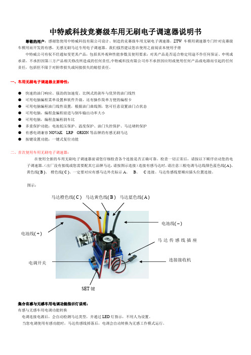
一、车用无刷电子调速器主要特性:● 快速的油门响应、强劲的加速度、比例式的刹车与优异的油门线性 ● 可用电脑编程菜单设置和软件升级,还有操作简单方便的编程卡 ● 可用电脑编程油门线性设置,根据油门曲线图,您可任意设置油门点状态 ● 可用电脑,编程盒编程前进与倒车输出功率大小 ● 可用电脑,编程盒编程刹车比● 多重保护功能:电池低压保护、温度保护、油门失控保护、马达堵转保护 ● 有感电调兼容NOV AK LRP ORION 等品牌的有感无刷马达 ● 按键设置功能;一键式复位功能二、首次使用车用无刷电子调速器:在使用全新的车用无刷电子调速器前请您仔细检查各个连接是否正确可靠。
检查一切正常后,请按以下顺序启动您的电子调速器。
(出厂没有接线或您需要配其它品牌马达,请按图示连接)连接有感马达时,请注意三根电调马达线颜色蓝色线( A )、 黄色线( B )、 橙色线( C )、一定要对应有感马达外壳标示A 、 B 、 C 连接。
马达传感线要顺应插头位置连接。
图示:集合有感与无感车用电调功能指示灯说明: 有感与无感车用电调功能转换电调连接电源后,会自动检测马达类型,并通过LED 灯指示,不用人为设置。
当您电调使用有感功能时,马达传感线掉落后,电调会自动转换为无感工作模式运行。
SET 键马达橙色线( C ) 马达黄色线( B ) 马达蓝色线( A ) 电池线( + )电池线( – )电调开关连接接收机马达传感线插座LED灯亮与闪烁指示相应功能说明有感/无感集成电调指示灯说明功能状态功能状态LED灯功能状态LED灯指示电池低压红色LED 闪烁电调与马达过热(95℃)红色橙色LED 长亮配用有感马达红色橙色LED 长亮配用无感马达橙色LED 长亮有感电调指示灯说明功能状态功能状态LED灯功能状态LED灯指示电池低压红色LED 闪烁电调与马达过热(95℃)红色橙色LED 长亮配用有感马达红色橙色LED 长亮正向模式. 红色 LED 长亮双向模式橙色LED 长亮无感电调指示灯说明功能状态功能状态LED灯功能状态LED灯指示电池低压红色LED 闪烁电调过热(95℃) 红色橙色LED 长亮配用无感马达橙色LED 长亮正向模式. 红色 LED 长亮正向模式. 红色 LED 长亮1.油门行程设定:首先关闭电调开关,连接电池,再打开您的车用发射机电源,将油门通道方向设置为(REV),油门微调设置为(0),油门通道的EPA/ATV正反向均设置为最大按下SET键不松开,将电调开关打到ON位,等待4秒左右,电调橙色LED亮,这时把SET键松开,同时把您的发射机油门拉杆拉最大,红色LED闪烁3秒左右长亮,马达滴响后;再把油门拉杆推到最小,橙色LED闪烁3秒左右长亮,马达滴滴响后;把发射机油门拉杆置自然位,红色LED、橙色LED、同时闪烁3秒左右长亮,马达滴滴响后,2个LED熄灭;油门行程设定OK, 关闭电调开关2.打开电调开关,您的电调现在可以工作了三. 可编程的车用无刷电子调速器功能说明与出厂默认图示:功能值编程项目1 2 3 4 5 6 7 8 91.低电压关断值2.6V/节 2.8V/节3.0V/节 3.2V/节 3.4V/节不保护2.运行模式单向带刹车双向带刹车3.马达进角2度4度6度8度12度4.启动加速度低中高最高5. 反向工作输出功率比20% 30% 40% 50% 60% 70% 80% 90%100%6.正向工作输出功率比0% 20% 30% 40% 50% 60% 70% 80%90%7.刹车力比10% 20% 30% 40% 50% 60% 70% 80%100%8.拖刹力比4% 8% 12% 15% 20% 25% 30%9.电调工作频率8KHz 16KHz10.油门自然位宽度2% 3% 4% 5% 6%四.可编程的车用无刷电子调速器功能说明:我们的车用无刷电子调速器允许您针对自身需求来编程所有功能,充分体现了产品以用户为本的特点1. 低电压关断值●自动检测电池节数.出厂默认3.0V/节关断根据您使用的电池,通过电脑软件或编程盒设置您的电池类型与低压关断值;这样可使电调工作时随时监测电池电压,一旦电池电压低于设置低压点,电调将停止工作.●当使用镍氢.镍隔电池时,您不需要设置关断电压来保护电池。
新编程卡系列无刷电调说明书

尊敬的用户: 感谢您对我们产品的信任,购买我们的无刷马达电子调速器。为了保障你的权益,
在使用本产品前请仔细阅读本说明书
注意事项: 使用前应完全阅读说明 只使用高质量的新插头,必须很好的焊接控制器的电线(插头不能有助焊剂残留物) 连接电池的电源线可以最大延长至20厘米 注意所有电线和接收机天线之间的距离,应尽可能地保持最大 在飞行器即将飞行前将电池连上飞行系统,登陆后马上断开 如果您不使用这个模型,请总是将所有电池与飞行系统断开 请勿将电子调速器或电池的极性接反、或使用不同型号的连接器 除了连接合适的电池(相应的输入电压和电流负载),请勿将电子调速器连接到直 流电源上 每次开机之前都要检查调速器和接收器电路和发射频率 请将模型中的调速器置于制冷气流中,并留一个通风孔以保证有充足的空气量(进 风孔和出风孔)
祝您飞行成功!
第4页
电子调速器安装 考虑到冷却效果、电线长度和接收机天线位置,请为调速器选择合适的位置 请将JR连接器插入接收器油门通道 传送器油门杆必须位于电机停止的位置上 连接飞行器电池(注意极性正确) 电池必须一次性连接OK,注意不能用插头多次插拔 电机发出“哔” 一声或“哔、哔” 两声说明连接正确,电子调速器一切就绪,等 待您推动油门启动电机 若听到“哔”一声,说明制动刹车已启动,若听到“哔、哔”两声,说明刹车功能 未启动 您现在可以使用油门杆来启动电机了 如果上述确认的蜂鸣声没有出现,请断开飞行器电池并检查:JR插头是否与油门通 道正确连接,油门摇杆是否处于最低位置(刹车/停止)或者传送器油门通道可能 处于相反位置 电机旋转方向的改变既可以通过电机和调速器之间3条连接线中的任意2条连接线 互换来实现,也可以通过调节ProgCard Pro程序卡来实现
关断电压模式 高 中 低
好盈设置卡说明
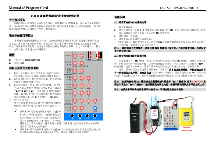
注 1: 请注意以下连接顺序:必须先将 BEC 排线插上设定卡,再给电调接电源,否则设定 卡不能正常工作。 二、对于无内部 BEC 电路的电调
如果电调上有“BEC OPTO”标记,说明该电调是没有内置 BEC 电路的,因此对于这类电 调,在用设定卡进行参数编程时,必须单独为设定卡供电,即需在设定卡右上角的“Batt.” 插座中接入电源(4.8-6V)。通常可以使用接收机电池组为设定卡供电,请参阅下图。
1
Manual of Program Card
设定方法说明
按 这个键,即可上下选择各个设定项,选择后该设定项的某个发光管会闪烁,然后按 这个键即可以选择要设定的参数,闪烁的发光管对应所选的参数值。设定好后,按 键。这 时蓝
色发光管闪烁,表示正在将设定的参数传送给电调,当电调保存参数后,蓝色发光管即熄灭。
音乐设定对照表:(● 表示发光管亮,○ 表示发光管灭)
发光管状态
曲名
发光管状态
曲名
DCBA
DCBA
○ ○ ○ ○ 关闭乐曲(无歌曲) ● ○ ○ ○ 铃儿响叮当(圣诞歌)
○ ○ ○ ● 苏珊娜
● ○ ○ ● 斗牛士之歌
○ ○ ●
● ○ ● ● 英雄凯旋曲
面板示意图及设定项说明
1. 刹车:开启刹车,则油门关闭后,马达迅速停止; 关闭刹车,则油门关闭后,马达随惯性逐渐停止。
2. 低电压保护方式:指当电池电压低于所设定的保 护阈值时采取的保护方式。
3. 低电保护阈值:当采用的是锂电池时,则“低/ 中/高”表示将每节锂电电压的保护点分别设为 “2.6V/2.85V/3.1V”;当采用的是镍氢/镍镉电 池时,则“低/中/高”表示将低电压保护点分别 设为初始输入电压的 0%(无保护)/45%/60%。
ProgCard II-编程卡说明

YPG系列ProgCard II-Programming Card有了程序卡,可以让你更加便捷地使用编程器来改变电子调速器的每一项功能。
一个显著特征就是市场上的两种锂电池都可以精确调整每节的截止电压。
而且,还可以通过按钮来调整进角、不同的刹车模式、定速规则及油门杆的准确位置。
所有的电子调速器都可以回读当前设置。
除了查看LED矩阵,还可以通过声音信号来确认相应的程序步骤是否完成,该信号是由马达连接电子调速器来产生的。
如果是使用遥控器杆编程,这一切的功能是不可能实现的。
操作指南:断开调速器上的飞行电池。
断开接收器(或光耦合器)的控制电缆,将编程电缆插入程序卡II的左侧连接器。
左连接是信号(白色、黄色、橙色),中间连接是5V(红色),右侧连接表示负极(棕色或黑色)。
如果不小心插错了位置,也不会有异常发生,因为该程序卡有反向保护。
OPTO的ESC你永远需要用到延长线,因为它是通过接收机来给编程卡II供电的。
现在将马达与ESC连接(带BEC的电调可以直接接入;不带BEC的电调,编程卡需通过接收机来供电的)。
此时,编程卡侧面LED列上方的LED灯会亮起。
ESC马达会发出6Beep声信号。
(短音)Level1不一会儿,ESC当前的设置会被读取,只要是带BEC的ESC。
整排所有的LED灯都会连续亮起并熄灭两遍(OPTO的ESC需要按回车键)。
这时进入Level1,进角LED开始指示。
此时你按左下方按键选择菜单栏,就可以在LED列阵里看到编程好的设置。
选择按左上角的按键,你可以选择新的值,按右侧的Enter键新的值将会被编入ESC设置。
ESC会发出正确的信号以示确认。
(LED灯会亮起,接下来会发出一低一高两个信号音)如果某些功能不能被编入ESC,会有错误的信号来提示。
(1声低音)可以像上面的方法调整电调所有功能,然而电调其他程序命令不会相应地改变,除非是Lipo 电池类型,并且还要注意紧接着调整截止电压及电芯数量。
好赢编程设定卡

松设置电调的所有参数。
编程卡小巧便携,非常适合在外场使用。
01· 工作电压:4.8-8.4V· 外形尺寸:88 x 58 x 14mm · 重量:40g02产品规格04功能说明05使用方法说明LED参数编程卡使用说明书3) 该编程卡仅适用于好盈科技有限公司出产的的无刷电调,不兼容其他厂家的电调。
所有连接完成后,将电调接上电池,打开电调开关。
等待几秒后,编程卡显示出电调的当前设定值。
如果连接好后,设定卡没有任何显示,请检查编程线及编程卡供电线是否插反,确认无误后先断开电调电源,等2秒后,再插上电源。
注意:编程卡要等待几秒钟以后才会显示数字。
1) ITEM键:按“ITEM”这个键,即可循环地选择各个设定项,选择时该设定项的序号会在左边的“ITEM”屏幕上显示出来。
2) VALUE键:选中某个设定项后,“VALUE”屏幕中会显示该设定项在电调内的当前参数值,按“VALUE”键即可以更改参数值。
3) OK键:更改完所有参数后,按“OK”键,这时在“VALUE”屏幕中间的位置上会出现红色的“—”标记约1至2秒钟,表示正在将设定的参数传送给电调,当电调保存参数后, 红色“—”标记随之消失。
4) RESET键:“RESET”键用于将车用电调的内部参数恢复为出厂默认值。
重贴标签(非必做项)1开启编程卡3设定方法说明4因各电调参数编程接口不同,电调与编程卡的连接方法也不同,请查看电调说明书对参数编程口的详细说明,再使用相应的接法即可,连接方法有以下几种:1) 电调编程线与油门线复用:· 若电调有BEC输出:将电调油门线插入编程卡右上角标注“ ”接口即可。
· 若电调无BEC输出(即OPTO 类型的电调):将电调油门线插入编程卡右上角标注“ ”接口;此外,还须用额外的电池(4.8-8.4V)给编程卡供电,电池插入编程卡右上角标 注“ ”接口。
2) 电调编程口与风扇接口共用:把风扇线拨出,编程线分别插入风扇接口及编程卡右上角标注“ ”接口即可。
康明斯电调说明书

目录序-------------------------------------2 功能介绍----------------------------3 安装说明----------------------------8 故障处理---------------------------11序电子调速系统是发动机速度调节系统,其主要任务是:保持发动机转速在设定转速运转。
机械调速和电子调速的不同之处在于:电子调速能够通过控制单元(1·Fig.1.)来“感受”实际转速与设定转速的不同,将此差值变换传给执行单元(执行器)来调节燃油流量从而增加或降低发动机转速转速,使之保持在设定转速运行。
Fig.1. 电子调速系统结构1、控制单元(调速板)4、停车阀/燃油阀2、发动机速度传感器5、电池3、执行器功能介绍发动机转速传感器发动机转速传感器安装于发动机飞轮壳上方正对飞轮,当飞轮齿经过转速传感器,传感器就产生一交流电信号(每一齿产生一个脉冲信号)。
脉冲电压在1V AC~30V AC之间转速传感器的安装螺纹是5/8”-18 UNF-2A Fig.2. 传感器部分1、转速传感器2、飞轮齿控制器(调速板)电子控制器(调速板)的基本功能是:比较输入转速信号与设定值,然后将校正或不变的指令传输给执行器。
调速板有以下调节功能,只须将黑色圆胶盖打开即可进行调节:1、调节怠速转速“IDLE”,把端子“G”和“M”短接,调节电位器(4·Fig.3.),调节频率范围在1200-4100HZ之间,顺时针调节电位器将增加怠速转速。
2、运行速度调节“SPEED”,频率调节范围在100-6000HZ,顺时针调节将增加发动机转速。
上面的调节频率来自电磁传感器(转速传感器),频率值取决于发动机飞轮齿数和发动机转速。
即:频率值=发动机转速(r/s)×发动机飞轮齿数例:CUMMINS NTA855-G1发动机齿数是118,转速在1500r/min(25r/s):25×118=2950HZ.Fig.3.调速板ESD55001、运行速度调节、设定 5、下垂调节2、增益调节、设定 6、启动燃油调节3、稳定性控制 7、转速坡度调节4、怠速调节注:不同型号调速板各电位器排列位置略有不同,请以标识为准3、增益调节“GAIN”,转速的灵敏度是通过调节“GAIN”电位器(2·Fig.3.)实现的,顺时针调节将使灵敏度增加;——顺时针调节“GAIN”电位器,直到发动机出现抖动,再旋回1/8圈;——当调整灵敏度时频率可能会有很小的变化,这个变化可通过调整“SPEED”电位器来调整。
车用无刷电调编程设定卡说明书

User Manual of The Program Card for ESC of Cars Doc Ver. HW-10A-V1-081119.1车用无刷电调编程设定卡使用说明书关于售后服务:尊敬的客户,我们的产品自售出之日起,提供180天的保修服务。
为了保护您的权益,请在购买产品时向销售商索取收据或发票,我们以此作为确定售出日期的凭证。
如无法提供收据或发票,我们将对产品实行有偿维修。
设定卡的作用和特点:感谢您使用编程设定卡产品,这款编程设定卡是用来对车用无刷电调进行参数设定的。
设定卡界面非常直观友好,通过它可以轻松设置车用电调的所有参数。
设定卡小巧便携,非常适合在外场使用。
规格:1.外形尺寸:88mm*58mm*14mm2.重量:40g设定项说明:1.运行模式(Running Mode)↓“正转带刹车”模式(Forward with brake):车辆仅能前进和刹车,不可以倒车;↓“正反转带刹车”模式(Forward / Reverse with brake):具有前进、倒车和刹车功能;↓“直接正反转”模式(Forward / Reverse):适用于攀岩车;2.拖刹力度(Drag Brake Force):拖刹是指当油门摇杆从正向区域(前进)转入中立点区域时,对电机产生一个微量的刹车力,这样做可以模拟有刷电机的碳刷对电机转子的阻力,适合减速入弯等场合。
该设定项有8个选项,拖刹力度递增;3.电池低压保护阈值(Low Voltage Cut-off):这项功能主要是防止锂电池过度放电而造成不可恢复的损坏。
因此在使用锂电池时,请勿选择为“无保护”,以免对锂电池造成损坏。
请根据您的使用习惯,设置合适的电压保护阈值;4.启动模式(Start Mode):选择启动的力度。
该项目也被称作“Punch”。
某些电调有9个可选参数,从“1级”至“9级”,有些电调有4个可选参数,从“1级”至“4级”,启动力度均为逐级增加。
中特威多功能LCD编程卡 G2 说明书
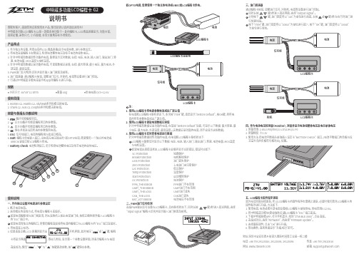
3.将电调接上电池。
4. 如果连接正确,LCD 屏幕则显示出 开机界面,此时按压“ ”或“ ”键,编程卡将显示界面 ,等待几秒后,显示第一个参数设置界面,则表示编程卡与电调 连接成功。
使用“ ”、“ ”与“ ”按键更改参数,按“ ”键保存参数。
说明书产品特点1. 作为独立的设备,利用自带的LCD(液晶屏幕)显示电调参数,进行参数设定。
2. 将电池连接编程卡右侧接口,检测电池整体电压及每节电池的单体电压。
3. 针对中特威有数据回传功能的电调,能够显示实时数据,包括: 电压、电流、输入油门、输出油门、转 速、电池电量、MOS温度与电机温度。
4. 针对中特威有数据记录功能的电调,可读取数据记录值,包括: 最大转速、最小电压、最大电流、外 部温度、最高温度。
5. PWM油门信号检测:识别并显示输入油门脉宽及频率。
6. 油门调速器: 通过编程卡按钮,调整油门信号,对舵机、电调等设备进行油门控制。
7. 可通过中特威蓝牙模块连接手机App对编程卡进行升级。
规格外形尺寸: 84*49*11.5mm 重量:40g 供电电源:DC5~12.6V使用范围1. Beatles G2、Mantis G2、Skyhawk系列航模无刷电调。
2. Shark G2、Seal G2、Dolphin系列船模无刷电调。
1. 断开电调电源。
2. 选择相应的连线方式,将电调与编程卡连接好。
如果电调编程线与油门线复用,则从接收机上拔出电调油门线,按照正确的顺序插入LCD编程卡 的“ESC”插口中。
如果电调有独立的编程口,则使用编程连接线将电调的编程口与LCD编程卡的“ESC”端口连接好。
按键与各插头功能说明使用说明一、 作为独立设备对电调进行参数设定注:1. 使用LCD编程卡将电调参数恢复成出厂默认值 在电调和LCD编程卡联机状态下,多次按“ITEM”键,直至显示“Restore Default”,按OK键,则将电 调的所有参数恢复成出厂默认值。
JIVE电调中文说明书_20101220

·由于译者水平有限,因此不能保证译文准确无误,不明确之处请对照原文自行鉴别·欢迎大家自由使用、分发、转载,敬请保留译者署名·译者联系方式:QQ:15109082 5imx帐号:guyama·欢迎以各种形式提出修改建议.最后修改时间2010-12-201 名词解释ESC 电子调速器APM 自动设置模式JIVE JIVE电调BEC 电池稳压电路EMF 电子刹车EMF刹车电子刹车跳线本说明书封面电调照片中左侧那个小东西LED 发光二极管ProgCARD JIVE电调设置卡,分为卡1和卡2信号表示:“哔哔哔”升调音“哔哔哔”降调音2 安全提示!电调需要充分的散热,避免由温度升高带来的问题。
·在电机运转时绝对不要把电池从JIVE ESC上拔下来。
·不要用把ESC和电线捆在一起,否则可能会损坏。
·当一个电池和电机与电调连接在一起,电机就有可能启动(比如:误操作或电子故障)·电机(特别是带着桨的)或者破损的零件可能会造成相当大的伤害。
·ESC仅允许在排除了对物体的损坏以及对人体的伤害可能性的情况下使用。
·在任何情况下使用损坏的ESC(比如:机械或者电子的影响,进水,等等),进一步使用将有可能导致ESC突发性的故障。
·ESC仅支持镍镉,镍氢,锂聚合物电池或铅酸电池,不支持除此以外的供电单元。
禁止与任何交流电网连接。
当使用高性能电池时,必须保证充分的散热。
·ESC只能在没有静电的环境下使用。
·不要延长电机线或者电池线,否则我们承诺的性能将无法得到保证。
延长线可能导致ESC 损坏。
·测量电流时,请使用非串联式的仪器(例如钳流表),串联式测量的器件可能会损坏ESC。
·当使用BEC时,必须并联上电量充足的接收电池,否则电线的破损、电池的损坏、插头的松动或者BEC部分的缺陷可能导致接收系统的失控。
好盈设置卡说明

无刷电调参数编程设定卡使用说明书
关于售后服务
尊敬的客户,我们的产品自售出之日起,提供 180 天的保修服务,因此为了保护您的权 益,请在购买产品时向销售商索取收据或发票,我们以此作为确定售出日期的凭证。如无法 提供收据或发票,我们将对产品实行有偿维修。
设定卡的作用和特点
面板示意图及设定项说明
1. 刹车:开启刹车,则油门关闭后,马达迅速停止; 关闭刹车,则油门关闭后,马达随惯性逐渐停止。
2. 低电压保护方式:指当电池电压低于所设定的保 护阈值时采取的保护方式。
3. 低电保护阈值:当采用的是锂电池时,则“低/ 中/高”表示将每节锂电电压的保护点分别设为 “2.6V/2.85V/3.1V”;当采用的是镍氢/镍镉电 池时,则“低/中/高”表示将低电压保护点分别 设为初始输入电压的 0%(无保护)/45%/60%。
1
Manual of Program Card
设定方法说明
按 这个键,即可上下选择各个设定项,选择后该设定项的某个发光管会闪烁,然后按 这个键即可以选择要设定的参数,闪烁的发光管对应所选的参数值。设定好后,按 键。这 时蓝
色发光管闪烁,表示正在将设定的参数传送给电调,当电调保存参数后,蓝色发光管即熄灭。
2
Doc Ver. HW-02A-090103.1
连接步骤
一、对于有内部 BEC 电路的电调 1. 断开电调电源。 2. 对于普通电调(支持 2-6 节锂电),请将电调上的 BEC 排线(控制线)从接收机上拔下
来,插到编程设定卡上右上角标注着 BEC 的插座里。 3. 将电调接上主电源。 4. 设定卡显示出电调的当前设定值。
○ ● ● ● 8 CELLS (29.6V) ● ● ● ● 自动检测锂电节数 注: 我们强烈建议用户手动设定锂电节数,而不要轻易选择“自动检测锂电节数”功能
船用无刷电机电子调速器(ESC)说明书

感谢您购买本产品!无刷动力系统功率强大,错误的使用可能造成人身伤害和设备损坏。
我们强烈建议您在使用设备前仔细阅读本说明书,并严格遵守规定的操作程序。
我们不承担因使用本产品而引起的任何责任,包括但不限于对附带损失或间接损失的赔偿责任;同时,我们不承担因擅自对产品进行修改所引起的任何责任。
我们有权在不经通知的情况下变更产品设计、外观、性能及使用要求。
【产品特色】↓完全针对船模而设计的全新程序算法,具有优异的启动效果和加速性能。
对行船过程中船体颠簸跳跃造成的负载突变有出色的适应能力;↓高品质用料和水冷散热系统确保电调具有强大的耐流能力。
↓防水设计,元器件涂敷防水胶并被良好密封,可有效延长电调使用寿命;↓具备正转(单向)和正反转(双向)两种运转模式;↓多重保护功能:具有温度保护、电池低压保护、油门失控保护功能。
保护动作方式专门针对船模而设计,更加合理和人性化;↓具有8个进角模式,良好匹配所有无刷电机。
您可以选择不同的进角实现输出功率的微调。
↓支持简单易用的参数设定卡(备注1:参数设定卡为选购件)。
【产品规格】【首次使用船用无刷电子调速器】警告!使用前请将船模架起,确保船桨不会碰到人或其他物体,以免发生安全事故!第一步:按图示接线,并复查无误后,进入下一步。
电调输出线A、B、C可以和电机线任意相连。
若电机转向不对,调转其中任意两条线即可。
第二步:设定油门行程。
强调!第一次使用电调或遥控器更改过油门中点、ATV、EPA等参数时,均需重设油门行程,不然可能会导致无法使用或误动作!请参照以下步骤,设定油门行程。
完成设定后,即可正常使用。
【开机过程说明】1.油门摇杆置于最低位置,打开遥控器;2.给电调接上电池;3.电机发出 N 声“哔-”鸣音,表示电池组有N节锂电,请确认鸣报的锂电池节数是否和您正在使用的电池节数一致。
如果只发出一声“哔-”鸣音,表示电调不做电池低压保护,这种情况仅适用于NiMH/NiCd 电池;4.加大油门,电机启动并加速。
- 1、下载文档前请自行甄别文档内容的完整性,平台不提供额外的编辑、内容补充、找答案等附加服务。
- 2、"仅部分预览"的文档,不可在线预览部分如存在完整性等问题,可反馈申请退款(可完整预览的文档不适用该条件!)。
- 3、如文档侵犯您的权益,请联系客服反馈,我们会尽快为您处理(人工客服工作时间:9:00-18:30)。
ProgCARD II Bedienungsanleitung Eigenschaften der ProgCARD IIDie ProgCARD II dient zur Einstellung individueller Parameter der JIVE Drehzahlregler Familien. Mit der ProgCARD II können auch Parameter verändert werden, die durch die Modusprogrammierung nicht oder nur eingeschränkt eingestellt werden können. Eigenschaften die beim Drehzahlregler nicht verfügbar sind werden nicht angezeigt. Sie werden bei der Selektion übersprungen.Anschlüsse und Bedienelemente der ProgCARD IIAuswahl (Taster) Kurz drücken springt zur nächsten Option Lang drücken speichert die angewählte Option abAnschluss …Regler“ Anschluss des zu programmierenden DrehzahlreglersAnschluss …Akku“ Anschluss des Verbindungskabels eines Empfängerakkus bei Drehzahlstellern ohne BEC Funktion.Verwendung der ProgCARD IIDie ProgCARD II muss mit dem …Master“ Anschluss des JIVE Drehzahlreglers polrichtig verbunden werden.Beim Anstecken eines Antriebsakkus an den Drehzahlregler werden zuerst die bereits eingestellten Parameter des Drehzahlstellers ausgelesen und mittels der LEDs angezeigt. Bei Reglern ohne BEC muss sowohl der Antriebsakku als auch ein Empfängerakku angeschlossen werden. Hinweis: Eine direkte Verbindung vom Empfänger zum Drehzahlregler darf für den Programmiervorgang nicht Jive 100+ LV>100A, 6-25V, BEC JMPLEDSlave MasterEinstellmöglichkeiten / Bedienung der ProgCARD II Einstelloption BeschreibungBEC Spannung Die Ausgangsspannung des BEC kann in 0,2V Schritten zwischen 5 und 6V eingestellt werden. Die Defaulteinstellung ist bei 5,6V.Bremsstärke Die max. Bremsstärke kann in 10% Schritten eingestellt werden.Feinjustage Die max. Bremsstärke kann in 2,5% Schritten ausgehend von der eingestellten Bremstärke feinjustiert werden.Drehzahlregelung Die Drehzahlregelung kann an die eigenen Bedürfnisse feinabgestimmt werden.Glättung + Die Drehzahlregelung arbeitet ruhiger und weicher. Das Heck steht ruhiger und der Kreisel muss weniger arbeiten.Glättung - Die Drehzahlregelung arbeitet schneller. Der Kreisel arbeitet mehr und das Heck wird nervöser.I-Anteil + Erhöhung der Integralverstärkung: Drehzahlabweichungen werden schneller ausgeregelt. Der Kreisel arbeitet entsprechend mehr.I-Anteil - Verringern der Integralverstärkung. Drehzahlabweichungen werden langsamer und sanfter ausgeregelt.P-Anteil + Erhöhung der Proportionalverstärkung. Drehzahlabweichungen werden schneller ausgeregelt. Der Kreisel arbeitet entsprechend mehr.P-Anteil - Verringern der Proportionalverstärkung. Drehzahlabweichungen werden langsamer und sanfter ausgeregelt.Drehrichtungsumkehr Die Drehrichtung des Motors wird umgekehrt.Hold 0,3s Die voreingestellten 3s Hold bei ungültigen Signalen werden auf 0,3s verkürzt. Die Originaleinstellung kann nur durch das Laden der Defaulteinstellung hergestellt werden.Lade Defaults Die Originalparameter der ProgCARD II bei Auslieferung werden geladenHinweise:•Zu viele “+“ Funktionen können die Regelung zum schwingen bringen, auch sind Wechselwirkungen mit Kreiselsystemen möglich•Auch “-“Funktionen können zu einer Verbesserung der Regelung führen. Die richtige Kombination führt zum besseren Ergebnis.•Die Verstellung der Drehzahlregelungsparameter erfolgt auf eigene Verantwortung, da eine unruhige oder schwingende Regelung starke Kräfte verursachen kann, die zu einer Beschädigung an den Bestandteilen eines Modells führen können•Beim Programmieren mit ProgCARD und ProgCARD II muss der Akku beim Wechsel der ProgCARDS immer abgezogen werden.•Der Flugakku muss immer an den Drehzahlregler angeschlossen werden•Zum Rücksetzen der Regelungseinstellungen, sowie der …Hold“ Funktion müssen erst die Standardeinstellungen geladen werden (…Lade Defaults“)Sicherheitshinweise•Der Betrieb der ProgCARD II ist nur in Situationen zulässig, in denen Sach- und Personenschäden ausgeschlossen sind.•Eine beschädigte ProgCARD II (z. B. durch mechanische oder elektrische Einwirkung, durch Feuchtigkeit, usw.) keinesfalls weiter verwenden. Anderenfalls kann es zu einem späteren Zeitpunkt zu einem plötzlichen Versagen kommen.•Die ProgCARD II ist nur zum Einsatz in Umgebungen vorgesehen, in denen keine Entladung von statischer Elektrizität auftritt.•Nicht die ProgCARD II mit Kabelbindern o.ä. befestigen. Es können Bauteile beschädigt werden.•Die ProgCARD darf nur aus NiCd-, NiMH-, LiPo-Akkus gespeist werden. Ein Betrieb an Netzgeräten ist nicht zulässig. Es darf in keinem Falle eine elektrische Verbindung zwischen der ProgCARD und dem 230V Wechsel-stromnetz hergestellt werden.RecyclingElektronische Bauteile dürfen nicht in den Hausmüll geraten, sondern müssen nach Gebrauch sach- und umweltgerecht entsorgt werden!Die nationalen und regionalen Abfallbestimmungen müssen befolgt werden. Elektronische Abfälle sindden dafür vorgesehenen Systemen der Getrenntentsorgung zu zuführen.Beratung / Technische Hilfe / HotlineTel.: +49 / (0)7457 / 9435-0FAX: +49 / (0)7457 / 9435-90Email: info@Homepage: Hotline : 0800 / BRUSHLESS (0800 / 278745377) - (aus Deutschland kostenlos)GewährleistungDie KONTROINK GmbH bietet 24 Monate Gewährleistung auf dieses Produkt bei Kauf in der EU. Produktkäufe außerhalb der EU entsprechen den jeweiligen gesetzlichen Vorschriften. Alle weitergehenden Ansprüche sind aus-geschlossen. Dies gilt insbesondere für Schadensersatzansprüche die durch Ausfall oder Fehlfunktion ausgelöst wurden. Für Personenschäden, Sachschäden und deren Folgen, die aus unserer Lieferung oder Arbeit entstehen,können wir, außer bei Vorsatz oder grober Fahrlässigkeit unsererseits, keine Haftung übernehmen, da uns eine Kontrolle der Handhabung und Anwendung nicht möglich ist.Zur Anerkennung der Garantie muss ein maschinenerstellter Originalkaufbeleg, auf dem das Produkt, das Kaufdatum und die Bezugsquelle erkennbar sind, beigelegt sein. Eine genaue Fehlerbeschreibung ist ebenso notwendig. (Verwendeter Motor, Luftschraube, Anzahl und Typ der Akkus. Wann trat der Fehler auf? Wurde vor dem Ausfall etwas außergewöhnliches bemerkt?)Bitte vergessen Sie nicht die korrekte Rücksendeadresse anzugeben.EG-KonformitätserklärungProgCARD II Operation Manual ProgCARD II Operation ManualFeatures of ProgCARD IIThe ProgCARD II programs ESCs of the JIVE series. Even options that cannot be programmed via mode programming of the ESC can be programmed by using ProgCARD II.Connectors of the ProgCARD II`Select`-Button Press shortly for selecting next option Press long for saving the selected optionESC-Connector ESC connection portBattery-Connector RX-battery connection portUsing ProgCARD IIThe ProgCARD II must be connected to the Master port of the JIVE ESC. As soon as the ESC is connected to the ProgCARD, set parameters are read out and are being displayed by LEDs on the ProgCARD II.Warning: The JIVE ESC must not be connected to the receiver when using the Jive 100+ LV>100A, 6-25V, BEC JMP LEDMaster SlaveUsing ProgCARD IIOption DescriptionBEC Voltage BEC voltage can be adjusted between 5V and 6V in 0.2V steps. Default setting is 5,6VBrake intensity Brake intensity can be adjusted between 10% and 100% in 10% stepsFine tune brake intensity Fine tuned brake intensity can be adjusted in 2,5% steps from the actual selected intensity.RPM Control The governor mode can be tuned by three different parameters. Smooth + Governor works softer, less work for the gyroSmooth - Governor works harder, tail may get nervousI-Gain + Integral gain ratio is increased, deviation of rotation speed will be reduced faster. Gyro will work more.I-Gain- Integral gain ratio is decreased, deviation of rotation speed will be reduced slower. Less work fort the gyro.P-Gain + Proportional gain ratio is increased, deviation of rotation speed will be reduced faster. Gyro will work more.P-Gain - Integral gain ratio is decreased, deviation of rotation speed will be reduced slower. Less work fort the gyro.Reverse Rotation drection The rotation direction of the motor can be reversed.Hold 0,3s Sets throttle hold when receiver signal is lost to 0.3s (default 3s)Load Defaults Restores factory defaultsHints:•Too many “+“ options may follow to a non stable governor, interaction with the gyro is possible•The governor can be optimized by using the “-“ Options too•Changing the governor options may result in an oscillating rotation speed. This causes very high loads to all components of a model. Damage cannot be excluded.•The battery must be disconnected when chaning between the ProgCARD and ProgCARD II•For using the ProgCARD II a battery must be connected to the ESC.•To reset governor options and hold option the factory defaults must be restored.Safety Notes•The use of the ProgCARD II is only permissible in situations in which damage of objects and injuries to persons are excluded.•Under no circumstances use a damaged ProgCARD II•The ProgCARD II is constructed only for use in environments in which no discharge of static electricity occurs.•Do not attach the ProgCARD II with cable ties, or similar. Electronic parts may be damaged.•The ProgCARD II may only be used with NiCd, NiMH, Lipo batteries. A use of power supply units is not permissible. Any contact to the AC mains network is prohibited.RecyclingElectronic components must not be disposed with household waste but have to be disposed according tolegal and environmental regulations. National and local disposal regulation have to be respected.Technical Support / Hotline/KONTRONIK ServiceTel.: +49 (0)7457 9435 0FAX: +49 (0)7457 9435 90Email: info@Homepage (worldwide): Homepage (USA / Canada): Hotline: 0800 / BRUSHLESS (+49 800 278745377) free when calling from GermanyKONTRONIK guarantees this product to be free from factory defects in material and workmanship for a period of 24 months from date of purchase and purchase within the EU. Warranty for purchases made outside the EU is inline with the respective legal regulations. This warranty does not cover: suitability for specific application, components worn by use, application of reverse or improper voltage, tampering, misuse or shipping. Our warranty liability shall be limited to repairing ore replacing the unit to our original specifications. Because we have no control over the installation or use of these products, in no case shall our liability exceed the original cost of the product. To accept guarantee the original bill on which the product the date of purchase and the dealer is named must be send with the product. Also a detailed fault description is necessary (used motor, propeller, count and type of batteries. When was the fault seen? Was there anything else unsuspected?). And don’t forget to write your address on the package!By the act of using this speed controller the user accepts all resulting liability.EG conformity declaration。
