罗斯蒙特硅表说明书
罗斯蒙特3051s 3051sf系列流量计多变量传感器快速入门指南说明书
Quick Start Guide00825-0100-4803, Rev GAOctober 2021 Rosemount™ 3051S and 3051SF Series Flow Meter MultiVariable™ TransmittersQuick Start Guide October 2021 ContentsAbout this guide (3)Mount the transmitter (5)Consider housing rotation (11)Set the switches (12)Connect wiring and power up (13)Engineering Assistant installation (17)Flow configuration (19)Verifying device configuration (28)Trimming the transmitter (32)Safety instrumented systems installation (33)Product certifications (34)2Rosemount 3051SMVOctober 2021Quick Start Guide1About this guideThis guide provides basic guidelines to install the Rosemount 3051SMultiVariable Transmitter. It also provides the basic Rosemount 3051SMVconfiguration guidelines for the Rosemount 3051SFA, Rosemount 3051SFC,and Rosemount 3051SFP. It does not provide instructions for detailedconfiguration, diagnostics, maintenance, service, troubleshooting, orinstallations. Refer to the Rosemount 3051SMV Reference Manual for moreinstruction. The manual and this guide are also available electronically at/Rosemount.1.1Safety messagesWARNINGFailure to follow these installation guidelines could result in death orserious injury.Ensure only qualified personnel perform the installation.ExplosionsExplosions could result in death or serious injury.Installation of device in an explosive environment must be in accordancewith appropriate local, national, and international standards, codes, andpractices.Review the Hazardous Locations Certifications for any restrictionsassociated with a safe installation.Process leaksProcess leaks could result in death or serious injury.Install and tighten thermowells and sensors before applying pressure.Do not remove the thermowell while in operation.Conduit/cable entriesUnless marked, the conduit/cable entries in the transmitter housing usea ½–14 NPT thread form. Entries marked “M20” are M20 × 1.5 threadform. On devices with multiple conduit entries, all entries will have thesame thread form. Only use plugs, adapters, glands, or conduit with acompatible thread form when closing these entries.When installing in a hazardous location, use only appropriately listed orEx certified plugs, glands, or adapters in cable/conduit entries.Quick Start Guide3Quick Start Guide October 2021 WARNINGElectrical shockElectrical shock could cause death or serious injury.Avoid contact with the leads and terminals. High voltage that may bepresent on leads can cause electrical shock.Unless marked, the conduit/cable entries in the housing use a ½–14 NPTthread form. Entries marked “M20” are M20 × 1.5 thread form. Ondevices with multiple conduit entries, all entries will have the samethread form. Only use plugs, adapters, glands, or conduit with acompatible thread form when closing these entries.When installing in a hazardous location, use only appropriately listed orEx certified plugs, glands, or adapters in cable/conduit entries.Physical accessUnauthorized personnel may potentially cause significant damage to and/ormisconfiguration of end users’ equipment. This could be intentional orunintentional and needs to be protected against.Physical security is an important part of any security program andfundamental to protecting your system. Restrict physical access byunauthorized personnel to protect end users’ assets. This is true for allsystems used within the facility.4Rosemount 3051SMVOctober 2021Quick Start Guide 2Mount the transmitter2.1Liquid flow applicationsProcedure1.Place taps to the side of the line.2.Mount beside or below the taps.3.Mount the transmitter so that the drain/vent valves are orientedupward.AA. Direction of flow2.2Gas flow applicationsProcedure1.Place taps in the top or side of the line.Mount beside or above the taps.2.A. Direction of flowQuick Start Guide52.3Steam flow applicationsProcedure1.Place taps to the side of the line.2.Mount beside or below the taps.3.Fill impulse lines with water.AA. Direction of flow2.4Mounting bracketsFigure 2-1: Mounting Bracket – Coplanar FlangePanel mountPipe mountQuick Start Guide October 2021 6Rosemount 3051SMVFigure 2-2: Mounting Brackets – Traditional FlangePanel mountPipe mountFigure 2-3: Mounting Brackets – In-linePanel mountPipe mount2.5Bolting considerationsIf the transmitter installation requires assembly of a process flange,manifold, or flange adapters, follow these assembly guidelines to ensure atight seal for optimal performance characteristics of the transmitter. Onlyuse bolts supplied with the transmitter or sold by Emerson as spare parts.Figure 2-4 illustrates common transmitter assemblies with the bolt lengthrequired for proper transmitter assembly.October 2021Quick Start Guide Quick Start Guide7Figure 2-4: Common Transmitter AssembliesA 4 × 1.75-in.(44 mm)D4 × 1.75-in.(44 mm)4 × 2.25-in.(57 mm)C4 × 1.75-in. (44 mm) 4 × 1.50-in.(38 mm)4 × 2.88-in.(73 mm)A.Transmitter with coplanar flange B.Transmitter with coplanar flange and optional flange adapters C.Transmitter with traditional flange and optional flange adapters D.Transmitter with coplanar flange and optional Rosemount Conventional Manifold and flange adaptersNoteFor all other manifolds, contact Customer Central technical support.Bolts are typically carbon steel or stainless steel. Confirm the material byviewing the markings on the head of the bolt and referencing Table 2-1 . Ifbolt material is not shown in Table 2-1, contact the local Emersonrepresentative for more information.Use the following bolt installation procedure:Procedure1.Carbon steel bolts do not require lubrication and the stainless steelbolts are coated with a lubricant to ease installation. However, noadditional lubricant should be applied when installing either type ofbolt.2.Finger-tighten the bolts.3.Torque the bolts to the initial torque value using a crossing pattern.See Table 2-1 for initial torque value.4.Torque the bolts to the final torque value using the same crossing pattern. See Table 2-1 for final torque value.Quick Start Guide October 20218Rosemount 3051SMVOctober 2021Quick Start Guide5.Verify the flange bolts are protruding through the sensor modulebefore applying pressure (see Figure 2-5).ExampleTable 2-1: Torque Values for the Flange and Flange Adapter BoltsFigure 2-5: Proper Bolt InstallationA.BoltB.Sensor moduleQuick Start Guide92.6O-rings with flange adaptersWARNINGFailure to install proper flange adapter O-rings may cause process leaks,which can result in death or serious injury. Only use the O-ring that isdesigned for its specific flange adapter.DA.Flange adapterB.O-ring C.PTFE-based profile (square)D.Elastomer profile (round)Whenever the flange or adapters are removed, visually inspect the O-rings.Replace them if there are any signs of damage, such as nicks or cuts. If the O-rings are replaced, re-torque the flange bolts and alignment screws afterinstallation to compensate for seating of the O-rings.Quick Start Guide October 202110Rosemount 3051SMV3Consider housing rotationTo improve field access to wiring or to better view the optional LCD display:Procedure1.Loosen the housing rotation set screw.2.Turn the housing up to 180° left or right of its original (as shipped)position.3.Re-tighten the housing rotation set screw.Figure 3-1: Transmitter Housing Set ScrewA.LCD displayB.Housing rotation set screw (3/32-in.)CAUTIONDo not rotate the housing more than 180° without first performing adisassembly procedure. Over-rotation may sever the electricalconnection between the sensor module and the electronics.4Set the switchesThe transmitter’s default configuration sets the alarm condition to high (HI)and the security to off.Procedure1.If the transmitter is installed, secure the bus and remove power.2.Required: Remove the transmitter cover opposite the field terminalside. Do not remove the instrument covers in explosiveenvironments when the circuit is live.3.Slide the Security and Alarm switches into the preferred position byusing a small screwdriver.NoteThe Security switch will need to be in the off position in order to makeany configuration changes.4.Required: In order to meet explosion-proof requirements, reinstallthe housing cover and tighten so the cover is fully seated with metalto metal contact between the housing and cover. After the cover isseated properly, replace the flathead screw located on the bottom ofthe housing cover.Figure 4-1: Transmitter Switch ConfigurationA BA.SecurityB.AC Termination5Connect wiring and power upCAUTIONDo not connect the power across the test terminals. Power could damagethe test diode in the test connection. Twisted pairs yield best results. Use 24to 14 AWG wire and do not exceed 5,000 ft. (1500 m).Use the following steps to wire the transmitter:Procedure1.Remove the cover on the field terminals side of the housing.2.Connect the positive lead to the “PWR/COMM +” terminal, and thenegative lead to the “PWR/COMM –” terminal.3.If the optional process temperature input is not installed, plug andseal the unused conduit connection. If the input is being utilized, seeInstall optional process temperature input (Pt 100 RTD sensor) formore information.When the enclosed pipe plug is utilized in the conduit opening, itmust be installed with a minimum engagement of five threads tocomply with explosion-proof requirements. Refer to the Rosemount™3051SMV Reference Manual for more information.4.If applicable, install wiring with a drip loop. Arrange the drip loopso the bottom is lower than the conduit connections and thetransmitter housing.5.Reinstall the housing cover and tighten so that metal contacts metalto meet explosion-proof requirements.Figure 5-1 shows the wiring connections necessary to power aRosemount 3051SMV and enable communications with a hand-heldField Communicator.Figure 5-1: Transmitter WiringA. Power supplyNoteInstallation of the transient protection terminal block does notprovide transient protection unless the Rosemount 3051SMVhousing is properly grounded.5.1Conduit electrical connector wiring (option GE or GM)For Rosemount 3051SMV with conduit electrical connectors GE or GM, referto the cordset manufacturer’s installation instructions for wiring details. ForFM Intrinsically Safe, Division 2 hazardous locations, install in accordancewith Rosemount drawing 03151-1009 to maintain outdoor rating (NEMA®4X and IP66). See the Rosemount 3051SMV Reference Manual.5.2Power supplyThe dc power supply should provide power with less than two percent ripple.The total resistance load is the sum of the resistance of the signal leads andthe load resistance of the controller, indicator, intrinsic safety barriers, andrelated components.Figure 5-2: Load Limitation5.3Install optional process temperature input (Pt 100 RTDsensor)NoteTo meet ATEX/IECEx Flameproof certification, only ATEX/IECEx Flameproofcables (temperature input code C30, C32, C33, or C34) may be used.Procedure1.Mount the Pt 100 RTD sensor in the appropriate location.NoteUse shielded four-wire cable for the process temperatureconnection.2.Connect the RTD cable to the Rosemount 3051SMV by inserting thecable wires through the unused housing conduit and connect to thefour screws on the transmitter terminal block. An appropriate cablegland should be used to seal the conduit opening around the cable.3.Connect the RTD cable shield wire to the ground lug in the housing.Figure 5-3: RTD Wiring ConnectionA.Ground lugB.RTD cable assembly wiresC.Pt 100 RTD sensor6Engineering Assistant installationEngineering Assistant 6.1 or laterThe Rosemount 3051SMV Engineering Assistant 6.1 or later is PC-basedsoftware that performs configuration, maintenance, diagnostic functions,and serves as the primary communication interface to the transmitter withthe fully compensated mass and energy flow feature board.The Rosemount 3051SMV Engineering Assistant software is required tocomplete the flow configuration.To ensure correct operation, download the most current version of theEngineering Assistant software at /Rosemount-Engineering-Assistant.6.1System requirementsThe following are the minimum system requirements to install theRosemount 3051SMV Engineering Assistant software:•Pentium®-grade processor: 500 MHz or faster•Operating system: Windows™ XP Professional (32-bit), or Windows 7 (32-bit or 64-bit)•256 MB RAM•100 MB free hard disk space•RS232 serial port or USB port (for use with HART® modem)•CD-ROM6.2Install Rosemount 3051SMV Engineering Assistant 6.1 orlaterProcedure1.Uninstall any existing versions of Engineering Assistant 6.2.Insert the new Engineering Assistant disk into the CD-ROM.3.Windows should detect the presence of a CD and start theinstallation program. Follow the on-screen prompts to finish theinstallation. If Windows does not detect the CD, use WindowsExplorer or My Computer to view the contents of the CD-ROM, andthen double click the SETUP.EXE program.4. A series of screens (Installation Wizard) will appear and assist in theinstallation process. Follow the on-screen prompts. It isrecommended to use the default installation settings.NoteEngineering Assistant versions 6.1 or later require the use ofMicrosoft®.NET Framework version 4.0 or later. If .NET version 4.0 isnot currently installed, the software will be automatically installedduring the Engineering Assistant installation. Microsoft .NET version4.0 requires an additional 200 MB of disk space.6.3Connect to a personal computerProcedure1.Remove the cover from the field terminals side of the housing.2.Power the device as outlined in Connect wiring and power up.3.Connect the HART modem cable to the PC.4.On the side of the transmitter marked “Field Terminals,” connect themodem mini-grabbers to the two terminals marked “PWR/COMM.”unch the Engineering Assistant software. For more information onlaunching software, see Launch Engineering Assistant 6.1 or later.6.Once the configuration is complete, replace cover and tighten untilmetal contacts metal to meet explosion-proof requirements.Figure 6-1 shows how to connect a computer to a Rosemount3051SMV.Figure 6-1: Connecting a PC to the TransmitterA.Power supplyB.Modem7Flow configurationRosemount 3051SMV Engineering Assistant 6.1 or laterThe Rosemount 3051SMV Engineering Assistant is designed to guide theuser through the setup of the flow configuration for a Rosemount 3051SMV.The flow configuration screens allow the user to specify the fluid, operatingconditions, and information about the primary element, including insidepipe diameter. This information will be used by the Rosemount 3051SMVEngineering Assistant software to create flow configuration parameters thatwill be sent to the transmitter or saved for future use.Online and offline modesThe Engineering Assistant software can be used in two modes: Online andOffline. In Online mode, the user can receive the configuration from thetransmitter, edit the configuration, send the changed configuration to thetransmitter, or save the configuration to a file. In offline mode, the user cancreate a new flow configuration and save the configuration to a file or openand modify an existing file.The following pages provide instructions on creating a new flowconfiguration in offline mode. For more information on other functionality,see the Rosemount 3051SMV Reference Manual.7.1Basic navigation overviewFigure 7-1: Engineering Assistant Basic Navigation OverviewAFGHB C D E7.2Launch Engineering Assistant 6.1 or laterFlow configuration for the Rosemount 3051SMV is achieved by launchingthe Engineering Assistant software from the Start menu.Procedure1.Select the Start menu→All Programs→Engineering Assistant.Engineering Assistant will open to the screen shown in Figure 7-2.2.Select Offline button located in the lower right hand corner of thescreen shown in Figure 7-2.Figure 7-2: Engineering Assistant Device Connection Screen7.3Use Preferences tabThe Preferences tab, shown in Figure 7-3, allows you to select the preferredengineering units to display.Procedure1.Select the preferred engineering units.2.If Custom Units are selected, configure the Individual Parameters.3.Check the box if unit preferences should be retained for futureEngineering Assistant sessions.Figure 7-3: Preferences Tab7.4Select fluid for database liquid/gasThe Fluid Selection tab shown in Figure 7-4 allows the user to choose theprocess fluid.Figure 7-4: Fluid Selection TabNoteThe following example will show a flow configuration for the database gas air used with a Rosemount 405C Conditioning Orifice Plate as the primary element. The procedure to set up any other fluid with any other primary element will be similar to this example. Natural gases, custom liquids, and custom gases require additional steps during the configuration. See the Rosemount 3051SMV Reference Manual for more information. Procedure1.Engineering Assistant may open to the Preferences tab. Using the tabsat the top of the screen, navigate to the Fluid Selection tab.2.Expand the Gas category (click on the + icon).3.Expand the Database Gas category.4.Select Air from the list of database fluids.5.Enter the Nominal Operating Pressure, select the Enter or Tab key.6.Enter the Nominal Operating Temperature, select the Enter or Tab key.Engineering Assistant will automatically fill in suggested operatingranges, as shown in Figure 7-4. These values may be edited asneeded by the user.7.Verify the Reference/Atmospheric Conditions are correct for theapplication. These values may be edited as needed.NoteReference pressure and temperature values are used by EngineeringAssistant to convert the flow rate from mass units to mass unitsexpressed as standard or normal volumetric units.8.Select Next to proceed to the Fluid Properties tab.7.5Fluid propertiesNoteThe Fluid Properties tab is an optional step and is not required to complete aflow configuration.The Fluid Properties tab for the database gas air is shown in Figure 7-5. This isused to verify the properties of the chosen fluid are acceptable.To check density, compressibility, and viscosity of the selected fluid at otherpressure and temperature values, enter a Pressure and Temperature andselect Calculate.NoteChanging the pressure and temperature values on the Fluid Properties tabdoes not affect the fluid configuration.Figure 7-5: Fluid Properties Tab7.6Select primary elementThe Primary Element Selection tab shown in Figure 7-6 allows the user tochoose the primary element.Figure 7-6: Primary Element Selection TabContinuing with the example configuration:Procedure1.Expand the Conditioning Orifice Plate category.2.Select 405C/3051SFC.3.Enter the measured Meter Tube Diameter (pipe ID) at a referencetemperature. If the meter tube diameter cannot be measured, selecta Nominal Pipe Size and Pipe Schedule to input an estimated valuefor the meter tube diameter (English units only).4.If necessary, edit the Meter Tube Material.5.Enter the Line Size and select the Beta of the conditioning orificeplate. The required primary element sizing parameters will bedifferent depending on what primary element was selected.6.If necessary, select a primary element Material from the dropdownmenu.7.Select Next > to advance to the Save/Send Configuration tab.NoteTo be in compliance with appropriate national or internationalstandards, beta ratios and differential producer diameters should bewithin the limits as listed in the applicable standards. TheEngineering Assistant software will alert the user if a primary element value exceeds these limits, but will allow the user to proceed with the flow configuration.7.7Save/send configurationThe Save/Send Configuration tab shown in Figure 7-7 allows you to verify,save, and send the configuration information to the transmitter with thefully compensated mass and energy flow feature board.Procedure1.Review the information under the Flow Configuration and DeviceConfiguration headings.NoteFor more information, see Verifying device configuration.Figure 7-7: Save/Send Configuration Tab2.Select the icon above each window to edit the configurationinformation in these windows.NoteThe user will be notified if the configuration has been modified sinceit was last sent to the transmitter. A warning message will be shownto the right of the Send Flow Data and/or Send Transmitter Data checkboxes.3.To send the configuration, select the Send To button.NoteThe Send Flow Data and Send Transmitter Data check boxes can beused to select what configuration data is sent to the transmitter. Ifeither check box is unselected, the corresponding data will not besent.4.The Engineering Assistant Device Connection screen will appear, seeFigure 7-8.Figure 7-8: Engineering Assistant Device Connection Screen5.Select the Search button located in the lower right hand corner ofthe screen. Engineering Assistant will begin to search for connected devices.6.When the search is completed, select the device to communicatewith and select Send Configuration button.NoteAfter the configuration is sent to the device, saving the configuration file is recommended. The user can select the Save button on theSave/Send screen or select Save from the program menu.Once the configuration is finished being sent to the device, the user will be notified by a pop-up dialog box.7.If finished with the configuration process, close EngineeringAssistant.8Verifying device configurationUse Rosemount 3051SMV Engineering Assistant or any HART-compliantmaster to communicate with and verify configuration of the Rosemount3051SMV.Table 8-1 shows the Field Communicator fast keys for the fully compensatedmass and energy flow. Table 8-2 shows the Fast Keys for the direct processvariable output.NoteDevice configuration procedures are given for Rosemount 3051SMVEngineering Assistant 6.1 or later and AMS Device Manager 9.0 or later in theRosemount 3051SMV Reference Manual.A check (✓) indicates the basic configuration parameters. At a minimum,these parameters should be verified as part of the configuration and startupprocedure.Table 8-1: Fast Keys for Fully Compensated Mass and Energy FlowTable 8-2: Fast Keys for Direct Process Variable Output9Trimming the transmitterTransmitters are shipped fully calibrated per request or by the factorydefault of full scale.9.1Zero trimA zero trim is a single-point adjustment used for compensating mountingposition and line pressure effects on static and differential pressure sensors.When performing a zero trim, ensure that the equalizing valve is open andall wet legs are filled to the correct level.The transmitter will only allow up to five percent of URL zero error to betrimmed.9.1.1Perform a zero trim using the Field CommunicatorProcedure1.Equalize or vent the transmitter and connect the FieldCommunicator (for more information on connecting,see Figure 5-1).2.If the device is equipped with a static pressure sensor, zero the sensorby inputting the following Fast Key sequence at the Rosemount3051SMV menu:e the zero trim (selection 1) for a transmitter equipped with a gagestatic pressure sensor or lower sensor trim (selection 2) for atransmitted equipped with an absolute static pressure sensor.NoteWhen performing a lower sensor trim on an absolute pressuresensor, it is possible to degrade the performance of the sensor ifinaccurate calibration equipment is used. Use a barometer that is atleast three times as accurate as the absolute sensor of thetransmitter.4.Zero the differential pressure sensor by inputting the following FastKey sequence at the Rosemount 3051SMV menu:10Safety instrumented systems installation For safety certified installations, refer to the appropriate reference manualfor the installation procedure and system requirements:•For DP only measurements (measurement type D) refer to theRosemount 3051S Reference Manual.•For MultiVariable measurements (measurement type 1–7) refer to the Rosemount 3051SMV Reference Manual.11Product certifications11.1Rosemount 3051SMV/3051SFxRev 2.10European directive informationA copy of the EC Declaration of Conformity can be found at the end of theQuick Start Guide. The most recent revision of the EC Declaration ofConformity can be found at /Rosemount.Ordinary location certificationAs standard, the transmitter has been examined and tested to determinethat the design meets the basic electrical, mechanical, and fire protectionrequirements by a nationally recognized test laboratory (NRTL) as accreditedby the Federal Occupational Safety and Health Administration (OSHA).Installing Equipment in North AmericaThe US National Electrical Code (NEC) and the Canadian Electrical Code(CEC) permit the use of Division marked equipment in Zones and Zonemarked equipment in Divisions. The markings must be suitable for the areaclassification, gas, and temperature class. This information is clearly definedin the respective codes.11.1.1USAE5 US Explosionproof (XP) and Dust-Ignitionproof (DIP)Certificate FM16US0089XStandards FM Class 3600 – 2011, FM Class 3615 – 2006, FM Class 3616 –2011, FM Class 3810 – 2005, ANSI/NEMA 250 – 2003 Markings XP CL I, DIV 1, GP B, C, D; T5; DIP CL II, DIV 1, GP E, F, G; CL III;T5(–50 °C ≤ T a ≤ +85 °C); Factory Sealed; Type 4XI5 US Intrinsically Safe (IS) and Nonincendive (NI)Certificate FM16US0233Standards FM Class 3600 –2011, FM Class 3610 – 2007, FM Class 3611 –2004, FM Class 3616 – 2006, FM Class 3810 – 2005, NEMA250 – 1991Markings IS CL I, DIV 1, GP A, B, C, D; CL II, DIV 1, GP E, F, G; Class III; Class1, Zone 0 AEx ia IIC T4; NI CL 1, DIV 2, GP A, B, C, D; T4(–50 °C ≤T a ≤ +70 °C) when connected per Rosemount drawing03151-1206; Type 4XNoteTransmitters marked with NI CL 1, DIV 2 can be installed in Division 2locations using general Division 2 wiring methods or Nonincendive FieldWiring (NIFW). See Drawing 03151-1206.US Intrinsic Safety (IS) and Nonincendive (NI)Certificate:1143113Standards:FM Class 3600:2011, FM Class 3610:2010, FM Class3611:2004, FM Class 3810:2005, UL50E (1st Ed.)Markings:IS Class I/II/III, Division 1, Groups A, B, C, D, T4/ E, F, and GT135 °C; Class I, Zone 0 AEx ia IIC T4 Ga;T4 (-50 °C ≤ T a ≤ +70 °C) [HART];T4 (-50 °C ≤ T a ≤ +60 °C) [Fieldbus];when connected per Rosemount drawing 03151-1207; Type4XIE US FISCO Intrinsically SafeCertificate FM16US0233Standards FM Class 3600 – 2011, FM Class 3610 – 2010, FM Class 3611 –2004, FM Class 3616 – 2006, FM Class 3810 – 2005, NEMA250 – 1991Markings IS CL I, DIV 1, GP A, B, C, D; T4(–50 °C ≤ Ta ≤ +70 °C); whenconnected per Rosemount drawing 03151-1006; Type 4X US FISCO Intrinsically SafeCertificate:1143113Standards:FM Class 3600:2011, FM Class 3610:2010, FM Class3611:2004, FM Class 3810:2005, UL50E (1st Ed.)Markings:IS Class I/II/III, Division 1, Groups A, B, C, D, T4/ E, F, and GT135 °C; Class I, Zone 0 AEx ia IIC T4 Ga;T4 (-50 °C ≤ T a ≤ +70 °C) [HART];T4 (-50 °C ≤ T a ≤ +60 °C) [Fieldbus];when connected per Rosemount drawing 03151-1207; Type4X11.1.2CanadaE6 Canada Explosionproof, Dust Ignition-proof, Division 2Certificate1143113。
罗斯蒙特5400说明书

1. 确保按照危险场所认证标准、国家和当地电气规范把外壳接地(包括端子隔室内部的本质 安全接地)。
2. 确保断开电源。 3. 卸下接线端子护盖 (见图)。 4. 把电缆穿过电缆压盖 / 配管。对于隔爆 / 防燃安装,应使用经过检定具有隔爆或防燃性能
的电缆压盖或配管进线装置。安装接线时打一个滴水环,滴水环的底部低于电缆 / 配管入 口。
合于工艺。 2. 把带天线和法兰的液位计降到储罐的喷嘴中。 3. 根据选择的法兰和垫片以足够的扭矩拧紧螺栓和螺母。
卡套 夹
夹持式储罐连接 1. 在储罐法兰上放置一个垫片。 2. 把液位计和天线降到储罐中。 3. 使用夹子把卡套紧固到储罐上。 4. 松开螺母,以转动液位计外壳。 5. 转动液位计外壳,使电缆入口 / 显示板面向所需方向。 6. 拧紧螺母。
*00825-0106-4026*
罗斯蒙特 5400 系列
© 2011 罗斯蒙特有限公司。保留所有权力。所有标识均为其所有者的财产。
快速安装指南
00825-0106-4026, EA 版 2011 年 8 月
艾默生过程控制 罗斯蒙特测量有限公司 美国明尼苏达州 Chanhassen 市 市场大道 8200 号, 55317 电话 (美国):1 800 999 9307 电话 (国际):+1 952 906 8888 传真:+1 952 949 7001
5. 按下列页面所示接线。 6. 卸下用于运输的橙色保护塑料塞。使用随附的金属塞将不用的端口密封。 7. 安装护盖,紧固电缆压盖,确保保护盖安全接合以符合隔爆要求(若使用 M20 电缆压盖,
则需要转接器)。 对于 ATEX、 IECEx、 NEPSI、 INMETRO 和 TIIS 安装,应使用锁紧螺钉锁紧护盖。 8. 连接电源。
罗斯蒙特305和306集中器产品数据表说明书

00813-0100-4733, Rev KA Catalog 2006 - 2007Rosemount 305 and 306 ManifoldsROSEMOUNT 305 AND 306 FEATURE...•Unique Coplanar ™ design of the Rosemount 3051 and 3095 families allows “flangeless” valve integration•Coplanar, traditional, and inline styles •Compact, lightweight assembly •Factory assembled, seal-tested and calibrated•Easy in-process calibration•50% fewer possible leak points thanconventional manifold/transmitter assemblies •Direct-mount capabilityContentsSpecifications . . . . . . . . . . . . . . . . . . . . . . . . . . . . . . . . . . . . . . . . . . . . . . . . . . . . . .page 4Dimensional Drawings. . . . . . . . . . . . . . . . . . . . . . . . . . . . . . . . . . . . . . . . . . . . . . . .page 7Ordering Information . . . . . . . . . . . . . . . . . . . . . . . . . . . . . . . . . . . . . . . . . . . . . . . .page 13Rosemount 305 and 306 Integral Manifolds00813-0100-4733, Rev KACatalog 2006 - 2007Rosemount 305 and 306 Manifolds2Rosemount 305R Coplanar Style Integral Manifolds305R TWO-VALVEThis two-valve manifold is used with Rosemount 3051 gage and absolute pressure transmitters. The first valve provides instrument isolation. The second valve allows venting, draining, or calibration through the test port.•305RC2 •305RT2•305RM2•305RC7305R THREE-VALVEThis three-valve manifold is used with Rosemount 3095 and 3051 differential pressure transmitters. It provides two blocking valves and one equalizing valve. Two drain/vent valves are also installed at the test ports.•305RC3•305RT3•305RM3•305RC8ROSEMOUNT 305R FIVE-VALVEThis five-valve manifold is used with 3095 and 3051 differential pressure transmitters. It provides two blocking valves, two test/vent valves, and oneequalizing valve. The two vent valves allow for 100% capture of vented or drained process, and simplified in-process calibration capability. We also offer a five-valve integral manifold with a metering pattern for Natural Gas installations.•305RC5•305RC6•305RC9•305RM5NOTEStandard two-valve and standard 5-valve manifold Test/Vents receive plastic caps to protect threaded connections.NOTEFive-valve Natural Gas Test (Plugged) connections receive 1/4-in. NPT plug.Coplanar TransmitterVent ValveCoplanar TransmitterTest \ Vent PortFIVE-VALVE NATURAL GASCoplanar TransmitterTest (Plugged)Test(Plugged)00813-0100-4733, Rev KA Catalog 2006 - 20073Rosemount 305 and 306 Manifolds306RT TWO-VALVE MANIFOLDSThis two-valve pressure manifold is used with 3051 and 2088 gage and absolute pressure transmitters. The first valve provides instrument isolation. The second valve allows venting, draining, or calibration through the test port. Available in 1/2–14 NPT male or female process connections.•306RT2306RT BLOCK-AND-BLEED MANIFOLDSThis pressure manifold is used with 3051 and 2088 gage and absolute pressure transmitters. It provides a single block valve for instrument isolation. There is also a plug for drain/vent capabilities. Available in 1/2–14 NPT male process connection.•306RT1Pressure TransmitterBleed ScrewPressure Transmitter00813-0100-4733, Rev KACatalog 2006 - 2007 Rosemount 305 and 306 Manifolds4SpecificationsFIGURE 1. 305R integral Manifolds - Pressure vs. Temperature(-18)(38)(149)(204)(260)(316)(371)(427)(538)Temperature °F (°C)Pressurepsig(bar)(93)(482)6092TABLE 1. 305R Integral manifolds - pressure and temperature ratings(1)Seat Pressure and Temperature Ratings PTFE Integral6092 psi @ 200°F (420 bar @ 93°C)4000 psi @ 400°F (276 bar @ 204°C) Graphite Integral6092 psi @ 200°F (420 bar @ 93°C)1500 psi @ 750°F (103 bar @ 399°C) Graphite (ASME B31.1)Integral6092 psi @ 100°F (420 bar @ 38°C)2915 psi @ 1000°F (201 bar @ 538°C) (1)Except option HK:PTFE, Integral seat: 2324 psi @ 200°F (160 bar @ 93°C), 1680 psi @ 400°F (116 bar @ 204°C)Graphite, Integral seat: 2324 psi @ 200°F (160 bar @ 93°C), 1125 psi @ 750°F (78 bar @ 399°C)00813-0100-4733, Rev KA Catalog 2006 - 20075Rosemount 305 and 306 ManifoldsFIGURE 2. 306R integral Manifolds - Pressure vs. Temperature10000(689)8000600040002000(-18)(38)(149)(204)(260)(316)(371)(427)(538)Temperature °F (°C)P r e s s u r e p s i g (b a r )(93)(482) TABLE 2. 306R Integral manifolds - pressure and temperature ratingsSeat Pressure and Temperature Ratings PTFE Integral 10000 psi @ 85°F (689 bar @ 29°C)4000 psi @ 400°F (276 bar @ 204°C)GraphiteIntegral 6000 psi @ 200°F (414 bar @ 93°C)1500 psi @ 750°F (103 bar @ 399°C)Graphite (ASME B31.1)Integral6000 psi @ 100°F (414 bar @ 38°C)2915 psi @ 1000°F (201 bar @ 538°C)TABLE 3. Process Wetted Materials of Construction - Typical (1)316SSTHastelloy C Monel316 SST with SG option Body (2)316 SSTHastelloy C-276Monel 400316 SSTBall / Tip 316 SST /316Ti SST Hastelloy C-276Monel 400 / K500Hastelloy C-276Stem 316 SSTHastelloy C-276Monel 400 / R-405Hastelloy C-276Packing PTFE / Graphite PTFE / Graphite PTFE / Graphite PTFE / Graphite Bonnet 316 SST Hastelloy C-276Monel 400 / R-405316 SST Pipe Plug 316 SSTHastelloy C-276Monel 400 / R-405316 SSTBleed Screw316 SST / 316Ti SST Hastelloy C-276Monel 400 / R-405 / K500Hastelloy C-276Drain / Vent Valve316 SSTHastelloy C-276Monel 400Hastelloy C-276(1)Non-wetted parts are 300 series SST.(2)Body may be supplied as appropriate cast equivalent.00813-0100-4733, Rev KACatalog 2006 - 2007 Rosemount 305 and 306 Manifolds6Shipping WeightsTest Connections1/4-18 NPTAdaptersDF option, CF-8M (Cast version of 316 SST, materialper ASTM-A743)Bolts for ManifoldsStandard material is plated carbon steel per ASTM A449, Type 1Alternative bolt materials offered through Option Codes•L4 Austenitic 316 Stainless Steel Bolts•L5 ASTM-A-193, Grade B7M Bolts•L8 ASTM-A-193, Class 2, Grade B8M BoltsISOLATION VALVENote: “Typical” ValveTABLE 4. 305 Manifold Weights Without Options, lb (kg)ModelApproximateManifoldWeightManifoldwith3051CManifold3051S_C (1)(1)3051S Module only; see Rosemount product data sheet00813-0100-4801 for additional information.Manifoldwith 30950305_C2 4.5 (2,0)9.4 (4,3)7.6 (3,4) 9.9 (4,5)0305_C3 4.7 (2,1)9.6 (4,4)7.8 (3,5)10.1 (4,6)0305_C5 6.5 (3,0)11.4 (5,17)9.6 (4,4)11.9 (5,4)0305_C6 6.4 (2,9)11.3 (5,1)9.5 (4,3)11.8 (5,35)0305_C7 4.7 (2,1)9.6 (4,4)7.8 (3,5)10.1 (4,6)0305_C8 5.0 (2,3)9.9 (4,5)8.1 (3,7)10.4 (4,8)0305_C9 6.3(2,85)11.2 (5,1)9.4 (4,25)11.7 (5,3)0305_T2 6.0 (2,7)10.9 (4,9)9.1 (4,1)–0305_T3 6.0 (2,7)10.9 (4,9)9.1 (4,1)–0305_T7 6.2 (2,8)11.1 (5,0)9.3 (4,2)–0305_T8 6.2 (2,8)11.1 (5,0)9.3 (4,2)–TABLE 5. 306 Manifold Weights Without Options, lb (kg)ModelApproximatelyManifoldWeightManifoldwith 3051TManifold3051S_T(1)(1)3051S Module only; see Rosemount product data sheet00813-0100-4801 for additional information.Manifoldwith 20880306_T1 1.1 (0,5) 4.1 (1,9) 2.5 (1,1) 3.1 (1,4)0306_T2 2.5 (1,1) 5.5 (2,5) 3.9 (1,7) 4.5 (2,0)0306_T3 2.5 (1,1) 5.5 (2,5) 3.9 (1,7) 4.5 (2,0)00813-0100-4733, Rev KA Catalog 2006 - 20077Rosemount 305 and 306 ManifoldsDimensional Drawings00813-0100-4733, Rev KACatalog 2006 - 2007Rosemount 305 and 306 Manifolds800813-0100-4733, Rev KA Catalog 2006 - 20079Rosemount 305 and 306 Manifolds00813-0100-4733, Rev KACatalog 2006 - 2007Rosemount 305 and 306 Manifolds101112Ordering InformationTABLE 6. Rosemount 305R Integral Manifolds0305Integral ManifoldR Rosemount Inc.C CoplanarT TraditionalM Traditional (Rosemount 3095-compatible; DIN-compliant flange)22-valve33-valve5(1)5-valve6(2)5-valve for natural gas/metering pattern7(2)(3)2-valve (per ASME B31.1[ANSI] power and piping code)8(2)(3)3-valve (per ASME B31.1[ANSI] power and piping code)9(2)(3)5-valve (per ASME B31.1[ANSI] power and piping code)2316 SST316 SST316 SST316 SST3(4)(5)Hastelloy® C Hastelloy C Hastelloy C Hastelloy C4(4)Monel®Monel Monel MonelA¼–18 NPT (Traditional manifold styles T and M)B1/2–14 NPT (Coplanar manifold style only)1Teflon2(6)Graphite-based1 Integral5Soft delrin (only available with natural gas/ metering pattern)13TABLE 6. Rosemount 305R Integral ManifoldsP2Cleaning for special services (Not available with graphite-based packing)SG(5)(7)316 SST NACE option (316 SST body and bonnet; Hastelloy C drain/vent, stem and tip/ball) for H2S ServiceL4(8)Austenitic 316 SST boltsL5ASTM-A-193-B7M boltsL8ASTM-A-193, Class 2, Grade B8M boltsCoplanar OptionsB4SST bracket for 2-in. pipe mount with series 300 SST boltsTraditional OptionsB1Bracket for 2-in. pipe mounting, CS boltsB3(9)Flat bracket for 2-in. pipe mounting, CS boltsB7B1 bracket with series 300 SST boltsB9(9)B3 bracket with series 300 SST boltsBA SST B1 bracket with series 300 SST boltsBC(9)SST B3 bracket with series 300 SST boltsBD SST Bracket with Series 300 SST Bolts for 305RM5 ManifoldsDF1/2–14 NPT flange adapters, Material of construction; match body material and packing material(Not available with graphite-based packing or HK, HL options)HK(10)10mm (M10) process flange bolting connectionHL(10)12mm (M12) process flange bolting connection(1)Not available with traditional manifold style T.(2)Only available with Coplanar manifold style(3)Only available with 316SST materials of construction and graphite-based packing.(4)Not available with traditional manifold Style M.(5)Materials of Construction comply with recommendations per NACE MR 0175/ISO 15156 for sour oil field production environments. Environmental limitsapply to certain materials. Consult latest standard for details. Selected materials also conform to NACE MR0103 for sour refining environments.(6)Includes graphite tape on drain/vent valves and plugs.(7)Only available with Materials of Construction Code 2: 316 SST body and bonnets; Hastelloy C stems, tip/balls, and drain/vents.(8)Not available with manifold codes 7, 8, and 9.(9)Not compatible with the Rosemount 3095 transmitter.(10)Only available with traditional manifold style M.14TABLE 7. Rosemount 306RT Integral Manifolds0306Pressure ManifoldR Rosemount Inc.T Threaded1Block-and-bleed22-valve3(1)2-valve (per ASME B31.1 [ANSI] power and piping code)2316 SST316 SST316 SST316 SST3(2)(3)Hastelloy C Hastelloy C Hastelloy C Hastelloy CAA1/2–14 male NPTBA(2)1/2–14 female NPT1Teflon2(4)Graphite-based1IntegralP2Cleaning for special services (Not available with graphite-based packing)SG(3)(5)316 SST NACE option (316 SST body and bonnet; Hastelloy C stem and tip/ball). For H2S Service3062211(1)Only available with 316SST materials of construction and graphite-based packing.(2)Not available with block-and-bleed manifold type(3)Materials of Construction comply with recommendations per NACE MR0175/ISO 15156 for sour oil field production environments. Environmental limitsapply to certain materials. Consult latest standard for details. Selected materials also conform to NACE MR0103 for sour refining environments.(4)Includes graphite tape on plugs.(5)Only available with material of construction code 2.15Emerson Process Management© 2006 Rosemount Inc. All rights reserved.¢00813-0100-4733w¤Rosemount and the Rosemount logotype are registered trademarks of Rosemount Inc.Coplanar is a trademark of Rosemount Inc.Monel is a registered trademark of International Nickel Co.Hastelloy is a registered trademark of Haynes InternationalTeflon is a registered trademark of E.I. du Pont de Nemours & Co.Emerson Process Management Heath Place Bognor Regis West Sussex PO22 9SH England T 44 (0) 1243 863121F 44 (0) 1243 867554Emerson Process Management Asia Pacific Private Limited 1 Pandan Crescent Singapore 128461T (65) 6777 8211F (65) 6777 0947Enquiries@AP Rosemount Inc.8200 Market BoulevardChanhassen, MN 55317 USA T(U.S.)180****9307T (International) (952) 906 8888F (952) 949 OPTIONS Module GuardA sensor module guard is available to protect the transmitter process isolating diaphragms. This guard should be used whenever the transmitter is removed from the integral manifold to avoid damage to the isolating diaphragms.•Part number: 00305-1000-0001 (5/pack)P2 Cleaning for Special ServicesThis option minimizes process contaminants by cleaning wetted surfaces with a suitable detergent.SG Sour GasMaterials of Construction comply withrecommendations per NACE MR 0175/ISO 15156 for sour oil field production environments. Environmental limits apply to certain materials. Consult lateststandard for details. Selected materials also conform to NACE MR0103 for sour refining environments.ASME B31.1 (ANSI)The 305 and 306 Manifolds are available inconfigurations that meet the requirements of ASME B31.1(ANSI) Power and Piping Code. This code specifies design criteria for most air, gas, steam, water, and oil systems used in electric generating systems, central and district heating systems,industrial power plants and geothermal plants. ASME B31.1(ANSI) includes requirements for manifolds, valves, and piping. Transmitters and other measuring devices do not fall within the scope of this code.MarkingManifolds are tagged with a part number, schematic drawing, temperature and pressure limits.Other PublicationsFor additional information, go to.3051-3031C 07F。
组态手册_中文显示(罗斯蒙特)
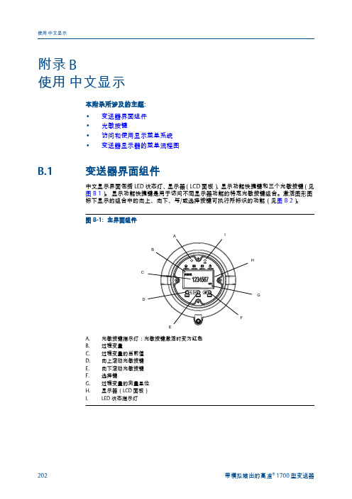
附录 B使用中文显示本附录所涉及的主题:•变送器界面组件•光敏按键•访问和使用显示菜单系统•变送器显示器的菜单流程图B.1变送器界面组件中文显示界面包括LED 状态灯、显示器(LCD 面板)、显示功能快捷键和三个光敏按键(见图 B-1)。
显示功能快捷键是用于访问不同显示器功能的特定光敏按键组合。
激活图形图标下显示的组合中的向上、向下、与/或选择按键可执行所标识的功能(见图 B-2)。
图B-2:显示器功能快捷键B CB.2按键组合显示在显示器前部,标识了可执行的特定功能。
要激活光敏按键,将拇指或其他手指挡在开口处,遮住灯光。
提示您可以隔着表盘激活光敏按键。
不要打开变送器外壳盖子。
如果将拇指或手指放在向上或向下光敏按键上而不移走,则可以激活持续滚动。
移走拇指或手指后,立即在当前选择处停止滚动。
变送器感应到光敏按键已激活后,光敏按键指示灯便会亮起。
表B-1:光敏按键指示灯和光敏按键状态B.3访问和使用显示菜单系统显示菜单系统用于执行各种组态、管理和维护任务。
提示显示菜单系统不提供完整的组态、管理或维护功能。
若要全面管理变送器,您必须使用其他通讯工具。
先决条件要访问显示菜单系统,则必须启用离线菜单或报警菜单二者中的任意一个的访问权限。
要访问整个菜单系统,则必须同时启用离线菜单和报警菜单的访问权限。
过程1.如果显示菜单已锁定,同时激活向上和选择光敏按键可解锁屏幕。
在屏幕无任何互动的三分钟后,显示菜单自动锁定。
2.在变送器显示器上,激活选择光敏按键,直到显示内容变化。
您将在几个位置中的任意一处进入离线维护菜单,具体取决于几个因素。
•如果有活动的报警并且启用了报警菜单的访问权限,您将看到报警。
•如果没有活动的报警,并且在变送器上启用了智能仪表在线自校验,您将看到在线校验。
•如果没有活动的报警,并且变送器上没有启用智能仪表在线自校验,您将看到离线维护。
3.使用向上、向下和选择光敏按键,导航至显示菜单系统中的目标位置。
罗斯蒙特氧化锆氧量分析仪表Oxymitter4000说明书

罗 斯 蒙 特 分 析 仪 器Oxymitter4000氧化锆氧量分析变送器操作手册(目录索引在最后一页)(IB-106-340)零件编号:系列编号:订单编号:注意:本说明书中所涉及到的仪器设备由以下厂商提供:罗斯蒙特分析仪器有限公司Rosemount Analytical, Inc.1201 North Main StreetOrrville, Ohio 44667USA1、罗斯蒙特郑重承诺由罗斯蒙特设计、生产、销售、装运的仪器设备,如出现技术上和生产上的质量问题,罗斯蒙特分析仪器有限公司将免费予以解决。
对于装运后出现的其它问题,罗斯蒙特分析仪器有限公司要求购买方首先提出书面通知,然后对需要更换的零部件,进行协商解决。
为保证分析仪器的质量,在履行上述条款时,如存在债务关系,则需要对上述条款进行协商后修订。
如前所述,罗斯蒙特分析仪器有限公司对危险区域Oxymitter4000氧化锆氧量分析变送器的质量承诺,无论是书面、还是口头或者暗示内容,均不包括任何其它型号的在线仪表。
对于合同中所签订质量承诺条款,罗斯蒙特分析仪器有限公司将严格遵守,如有违反,负责进行相应的赔偿。
在质保期内,对于环境因素造成的分析仪器质量衰减,属于正常范围,罗斯蒙特将不予以质量保证。
这些环境因素是指腐蚀性气体和沉积颗粒物损害了分析仪表而造成的零部件更换。
该分析仪表一旦由罗斯蒙特分析仪器有限公司供应,不管是否由罗斯蒙特生产,均遵守相同的承诺条款。
2、编制该说明书的目的编制该说明书的目的在于提供一份书面材料,以便用户对Oxymitter4000氧化锆氧量分析变送器的组件、功能、性能、安装、使用和维护有一个全面的了解。
本说明书全面介绍了Oxymitter4000氧化锆氧量分析变送器的相关信息,建议用户在安装和使用之前,透彻地了解绪论部分和安装部分的有关说明。
绪论部分介绍了分析仪表各组件的性能和功能原理,剩余部分介绍了安装信息和维修服务信息。
艾默生罗斯蒙特超声波液位变送器手册说明书

display for simple diagnosis. Linearization function (up to 32 points) for conversion of the measured value into any unit of length, volume or flow rate. silver tiger baccarat strategy pdf Two-wire or four wire instrument for continuous non-contact level and flow measurement.pastes, sludges and powdery to coarse bulk materials. The measurement is unaffected by dielectric constant, density or humidity and also unaffected by build-up due to the self-cleaning effect of the sensors.easy planning and assembly, fast and safe commissioning, a long service life and reduced maintenance costs.Typical applications include abrasive and aggressive media, even in rough ambient conditions. Measuring Principle Ultrasonic with Time-of-Flight Prosonic is based on the Time-of-Flight principle. A sensor emits ultrasonic pulses, the surface of the media reflects the signal and the sensor detects it again.The Time-of-Flight of the reflected ultrasonic signal is directly proportional to the distance traveled. With the known tank geometry the level can be calculated. Non-contact, maintenance-free measurement Measurement unaffected by media properties, like dc value or densityCalibration without filling or discharging Self-cleaning effect due to vibrating sensor diaphragm。
硅表说明书
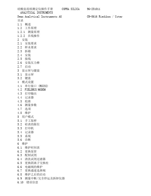
硅酸盐连续测定仪操作手册 COPRA SILICA 96-251011ANALYTICAL INSTRUMENTSSwan Analytical Instruments AG CH-8616 Riedikon / Uster 目录1.1 概述1.2 工作原理1.2.1 测量原理1.2.2 在线操作2 安装2.1 安装要求2.2 样水要求2.3 拆箱2.4 安装2.5 接线2.6 安装压力棒2.7 启动3 显示屏与键盘3.1 显示屏3.2 键盘4 模式设置4.1 串行接口 (RS232)4.2 FIELDBUS/MODEM4.3 打印输出4.4 记录器4.5 校准4.6 测量参数4.7 选项4.8 维护5 用户模式5.1 手工取样5.2 硅表的限位5.3 打印机5.4 记录器5.5 系统5.6 诊断6 维护6.1 维护时间表6.2 更换泵管6.3 配制试剂6.4 清洗试剂过滤器6.5 更换阴离子交换柱6.6 电磁阀的维护6.7 更换通道选择阀6.8 维护之后的启动6.9 测量中断/完全停运及拆卸仪器6.10 错误信息警告仪表符合DIN57411 part 1/VDE 041 part 1、“电子测量仪保护措施”,并且在无故障条件下出厂。
为了保持这种无故障状态和保证无操作错误,用户必须重视所有的警告并且严格按照《操作手册》操作。
严禁不接地。
外部或内部保护地线的断裂或松弛可能会导致危险。
当需要进行电气检修时必需在未通电状态下。
打开仪表或移动其部件时须小心,连接应紧固。
检修须由指定人员进行。
若仪表不能正常运行,就必须切断所有电源,并停止操作。
如有下述情况发生,不能进行安全操作:- 在运输或安装过程中明显损坏。
- 仪表不工作。
- 在不良环境下储存期过长仪表附件的任何连接都必须按照IEC 950/EN 60950,UL1950或UL478标准。
注意:没有试剂仪表不能工作。
试剂可以在Swan公司各地的经销商处购买。
罗斯蒙特475中文版说明书

2011年2月475 现场通讯器彩色并具有图形功能的用户界面强大的现场诊断功能475 现场通讯器适用于所有供应商的HART 及 F fieldbus 注册设备。
475现场通讯器是在具有行业领先技术的 375现场通讯器的基础上开发的, 同时还增加了创新性的新功能, 包括彩色显示屏,蓝牙通讯和先进的现场诊断。
耐用和可靠。
作为单一的手操器, 只有475现场通讯器可以同时提供所有这些功能。
你所获得的是目前功能最强大的手操器—通用, 用户可升级, 本安,坚固蓝牙通讯接口OUNDATION长时间持续使用的锂离子电源模块全面支持 HART 和F fieldbus 现场总线设备OUNDATION2011年2月通过 ValveLink Mobile 和增强的图形功能在现场进行高级故障诊断475现场通讯器的设计理念在于简化你在现场的工作。
用户在操作HART 和FF 现场总线设备时, 都可体验到直观的彩色图形界面。
它的触摸屏幕比PDA 或掌上电脑还大,支持 HART 协议版本5, 6和 7 (包括WirelessHART) 的设备, 并能通过互联网进行升级。
无论是在仪表间还是在现场, 触摸感应屏幕和加大的操作按钮令使用更为快捷方便。
475现场通讯器可由用户通过互联网随时升级, 从而避免了因送往服务中心所导致的时间拖延。
带有便利升级选项的手操器, 可以下载最新的设备描述文件(DDs), 新的功能, 或直接获得新的许可授权选项。
保持 475现场通讯器更新就是这样简单。
仪表供应商持续不断地推出新的HART 和FF 现场总线设备, 并对现 有设备不断进行功能升级, 保持厂 里所有设备的设备描述(DDs)更新是一件具有挑战性的工作。
现在有了便利升级功能,当新的HART 和Ff 现场总线设备描述文件(DDs )发布时, 只需要从互联网直接下载就可以升级475现场通 讯器了。
随时保持更新,一切尽在您的掌握之中。
彩色图形功能是每台475现场通讯器的标准配置。
罗斯蒙特3051说明书
4 x 73 毫米 (2.88 英寸)
4 x 44 毫米 (1.75 英寸)
4 x 38 毫米 (1.50 英寸)
4 x 44 毫米 (1.75 英寸)
螺栓通常是碳钢或不锈钢材质。请对照图 2 查看螺栓顶部的标记来确定螺栓材质。如果螺栓材质 未显示在图 2 中,请咨询当地的艾默生过程管理代表,获取更多信息。
6
快速安装指南
00825-0106-4801, KC 版 2011 年 11 月
第 1 步接上页 ...
图 2. 法兰和法兰接头螺栓的扭矩值 螺栓材质 碳钢 (CS)
不锈钢 (SST) 316
316 R
顶部标志
B7M
B8M 316
STM
SW
316
316
罗斯蒙特 3051S 型
初始扭矩值 300 英寸 - 磅
请按照以下步骤安装螺栓:
1. 碳钢螺栓无需润滑;不锈钢螺栓带有润滑涂层,非常易于安装。但是,安装任何一种螺栓时都 不能额外涂敷润滑剂。
2. 先用手把螺栓拧紧。 3. 按照初始力矩值交叉拧紧螺栓。有关初始扭矩值,请参见图 2。 4. 按照最终扭矩值交叉拧紧螺栓。有关最终扭矩值,请参见图 2。 5. 在加压前,检查确认法兰螺栓根部凸出安装终止面。
法兰接头 O 型圈
PTFE 类弹性材料
罗斯蒙特 1151
法兰接头 O 型圈
PTFE 合成橡胶
无论何时拆卸法兰或者接头,都要目视检查 O 型圈。如果有任何损坏的迹象(例如刻痕或切口), 请予以更换。若更换了 O 型圈,则在安装后应重新拧紧法兰螺栓和定位螺钉,以补偿 PTFE O 型 圈的安放。
7
罗斯蒙特 3051S 型
警告
爆炸可能会导致死亡或严重伤害:
罗斯蒙特差压流量计产品手册说明书

差压流量产品手册更具灵活性的流量测量方式“罗斯蒙特差压流量”更具灵活性的流量测量方式应用领域 – 液体,气体,蒸汽流量测量面临的挑战技术标准的不确定性带来的高风险潜在泄漏点带来的安全隐患特殊工况无法实现停车检修双向流、腐蚀介质、小管道流量导致测量难度大读数误差、小流量测量和直管段不足会降低测量精度大管径管道测量带来的高成本测量时压损过大带来的能源损失降低使用风险一体化流量计出厂前通过整体标定保证系统测量精度一体化设计和出厂前泄漏检测可大幅减少泄漏点,从而避免潜在安全隐患严格的原材料管理体系,保证所有物料可追溯,实现产品质量有效控制应对特殊工况针对无法停车检修的工况,可采用在线插拔安装方式一次元件可提供多种不同材质,来应对腐蚀工况面对双向流测量,可根据实际情况,提供更理想解决方案减少运营成本一体化安装可降低施工及维护成本阿牛巴流量计,在保证超强差压信号的前提下,更大程度减少永久压损调整型孔板大幅降低直管段需求,从而降低管道成本性能出色实时动态多参量补偿,提高流量测量精度可提供15年稳定性,15年质保流量计量程比大,适用范围广Rosemount差压流量计的优势13051SMV实时动态补偿实现蒸汽质量流量的精准测量挑战石化行业蒸汽总管线与分支管线流量差值很大,平衡率仅为70%。
由于无法准确计量各装置蒸汽用量,导致很难准确核算能耗成本。
解决方案采用罗斯蒙特3051SMV多参量变送器,测量差压、静压和温度数值,实现实时温压补偿。
同时实时计算动态补偿的质量流量,并修正来自于流量系数、密度、气体膨胀以及粘度的误差,从而提高测量精度。
方案优势提高测量的准确性和可重复性,实现更好的工艺控制通过精确的流量控制,帮助工厂有效的进行能源管理,能耗平衡率达到92%以上2多参量流量变送器大幅提高流量测量精度一流的性能变送器最高精度可达到读数的0.04%一台表可以同时测量并计算六个流量相关的变量:差压、压力、温度、质量/体积流量、热量累积器 兼容不同种类流量测量元件严格的流量计量标准内嵌IAPWS-IF97数据库: 水蒸汽计量全球标准 符合国家标准蒸汽热值输出标准动态补偿为流量方程中多达25个流体变量参数提供实时动态补偿优化能源计量提高收益变送器直接显示补偿后的质量流量或能量流量变送器三合一卓越特性Calendar-Van Dusen 传感器匹配提高温度测量精度提高精度 75%真正的表压传感器更容易标定简化维护小流量信号切除可停止无流量时的累计改善精度差压传感器静压传感器减少管道开孔,降低安装成本易于组态和标定EA 软件实现快速且简单的过程组态 可兼容市面上不同种类的差压流量测量元件节约安装和维护成本3差压变送器压力变送器温度变送器阿牛巴的广泛应用大管道的蒸汽流量精确测量流量计,压损小,测量精度高,不仅精确测蒸汽流量,还可实现蒸汽的热值输出。
(详细)罗斯蒙特1056双通道变送器中文说明书

使用说明书Model1056双通道智能分析仪目录快速启动指南 (2)快速启动指南树形图 (3)快速参考指南树形图 (4)一、通用技术规格 (5)①接触式电导率 (6)② pH/ORP/ISE (7)二、安装 (8)三、接线 (13)四、变送器的操作 (18)快速启动指南1.安装方式,请参见2.0章节。
2.传感器与信号板之间的接线,请参见3.0章节和有关传感器的说明。
同时,要求准确连接电源线和输出信号线。
3.只有在检查分析仪接线准确无误的情况下,才能给分析仪供电。
4.分析器第一次通电,快速启动(Quick Start)画面就会出现。
快速启动程序的使用非常简单。
A.闪烁区表示光标当前所在位置。
B.使用“左”、“右”箭头键,可以左右移动光标或改变小数点的位置。
使用“上”、“下”箭头键,可以上下移动光标或增加、减少数字。
C.按ENTER键,保存组态设置;按EXIT键,退出且不保存变更设置。
在快速启动过程中,按EXIT键也可以使显示器回到初始画面(选择语言)。
5.按照快速启动指南的组态树形菜单结构图(图A),完成仪器组态。
6.在完成最后一步组态后,仪器出现主显示屏幕,此时输出为默认值。
7.如果要改变输出和温度设置,请回到主菜单,选择程序“Program”,然后,按照快速参考指南的树形菜单结构图(图B),完成修改。
8.如果要使分析仪恢复到默认设置,请在Program下选择Reset Analyzer(分析仪复位)。
一、通用技术规格外壳:材质为聚碳酸脂,防护等级为NEMA 4X/CSA 4(IP65);尺寸:外形尺寸155×155×131毫米(6.10×6.10×5.15英寸);仪表盘开孔尺寸1/2 DIN标准,139×139毫米(5.45×5.45英寸);进线孔规格:½英寸或PG13.5穿线管;显示:单色LCD显示,显示分辨率128×96,背光照明,有效显示面积58×78毫米(2.3×3.0英寸);环境温度和湿度:环境温度为0-50℃(32-122℉),相对湿度为5-95%RH(无冷凝);贮存温度:-20至60℃(-4至140℉);电源:选型代码-01:115/230±15%VAC,50/60Hz,功耗10瓦;选型代码-02:20-30VDC,功耗15瓦;选型代码-03:85-265VAC,47.5-65.0Hz,通用电源,功耗15瓦;备注:选型代码-02和-03带4个可组态的继电器。
罗斯蒙特(Rosemount) 5408和5408 SIS液位变送器安装指南说明书

快速安装指南00825-0506-4408, Rev BC2022 年 4 月Rosemount™ 5408 和 5408:SIS 液位变送器过程密封天线快速安装指南2022 年 4 月内容关于本指南 (3)确认认证类型 (5)安装法兰式 (6)安装 Tri Clamp 版 (8)安装支架 (9)对准变送器表头 (10)调整显示屏方向(可选) (12)准备电气连接件 (13)接线和通电 (20)组态 (24)2Rosemount 5408 和 5408:SIS 液位变送器2022 年 4 月快速安装指南1关于本指南本《快速安装指南》提供 Rosemount 5408 和 5408:SIS 液位变送器的基本安装指导。
有关更多说明,请参阅《带有 HART®的 Rosemount 5408 和5408:SIS 参考手册》和《带有 F OUNDATION™现场总线的 Rosemount 5408 参考手册》。
这些手册和本指南的电子版本也可以从/Rosemount获得。
1.1安全信息警告不遵守安全安装与检修准则,可能导致死亡或严重受伤。
请确保由取得相关资质人员按照相应的操作规程安装变送器。
只能使用本手册中规定的设备。
未按照法规操作,可能削弱设备的防护能力。
对于危险场所的安装,必须按照罗斯蒙特 5408 和 5408:SIS 产品认证文档和系统控制图 (D7000002-885) 安装变送器。
修理设备(例如更换组件等)可能危害安全性,在任何情况下都是不允许的。
警告爆炸可能会导致死亡或严重受伤。
应验证变送器的工作环境是否与相应的危险场所认证一致。
在易爆气体环境中,连接手持通讯器之前,请确保按照本质安全或非易燃现场接线实践安装仪表。
在进行防爆/隔爆以及非易爆/ n 类安装时,不得在设备通电的情况下拆卸变送器盖。
为满足防爆/隔爆要求,变送器的两个盖子都必须完全盖上。
快速安装指南3快速安装指南2022 年 4 月警告触电可能导致死亡或严重受伤。
(完整word版)罗斯蒙特流量计操作说明。中文
目录第一章传感器安装 (2)1.1 概述 (2)1。
2 安装注意事项 (2)1.3 传感器的安装方向 (3)1.4 电气连接注意事项 (4)第二章仪表接线与上电 (5)2.1 概述 (5)2。
2 变送器的型号识别。
(5)2.3 变送器与传感器连接 (6)2.4 最大布线距离 (7)2.5 电源规格 (8)2。
6 变送器、显示组件方向调整 (9)2.7 变送器输出 (11)第三章流量计组态 (14)3。
1 概述 (14)3。
2 组态项目 (14)3。
3 变送器的显示器面板结构 (15)3.4 组态过程变量的测量单位 (15)3。
5 组态变送器的毫安输出 (16)3。
6 组态变送器的脉冲/频率输出 (16)3.7 变送器的回路测试 (17)3.8 显示器菜单功能 (3)3.9 流量计调零 (26)第四章流量计投用及报警状态 (27)4。
1 流量计投用 (27)4。
2 获取报警 (27)附录 1 报警代码含义表 (28)附录2 核心处理器检查 (33)附录3 传感器检查 (34)附录4 软件版本 4.x变送器的显示器菜单 (36)第一章传感器安装1。
1 概述相对于其他类型的流量计,质量流量计具有安装简便、易于使用、测量精度高以及直接质量测量等优点,尤其是没有直管段要求的特点,用户可因地制宜的选择安装位置,节约安装成本.1.2 安装注意事项1.2。
1 安装位置应避免电磁干扰。
传感器、变送器的安装位置以及电缆铺设应尽量远离易产生强电磁场的设备,如大功率马达、变压器设施、变频设备等。
1。
2。
2 工艺管道应对中,两侧法兰应平行.严禁用传感器硬行拉直上、下游工艺管道,否则将影响测量甚至损坏传感器。
另外在两侧的工艺管道近法兰处(约2~10倍管径处)应有稳固的支撑.1。
2。
3 在传感器的上、下游管道上,建议安装截止阀及旁路以方便调零、日常维护及确保传感器在不工作时亦可处于满管状态.使用流量计下游的调节阀进行流量控制。
罗斯蒙特3051说明书)
HART ®罗斯蒙特3051智能型© 2004 罗斯蒙特公司(Rosemount Inc.)版权所有。
所有标识为罗斯蒙特专有。
Rosemount 和Rosemount 的标识均为罗斯蒙特公司的注册商标。
开始结束压力变送器Rosemount Inc.8200 Market Boulevard Chanhassen, MN USA 55317 T (US) (800) 999-9307T (Intnl) (952) 906-8888F (952) 949-7001Emerson Process Management GmbH & Co. OHGArgelsrieder Feld 382234 WesslingGermanyT 49 (8153) 9390F49 (8153) 939172Emerson Process Management Asia Pacific Private Limited1 Pandan CrescentSingapore 128461T (65) 6777 8211F (65) 6777 0947/65 6777 0743北京远东罗斯蒙特仪表有限公司中华人民共和国北京市东城区和平里北街6号 100013电话 (86) (10) 6428 2233传真 (86) (10) 6422 8586本安装手册提供了Rosemount®公司3051系列变送器安装的基本指导方针。
不提供组态、诊断、维护、检修、排除故障、防爆防燃以及本质安全(I.S.)等的安装指导。
更多的操作指导请查阅3051产品参考手册(文件编号00809-0100-4001),也可访问我们的网站查阅手册的电子版本。
爆炸可能会导致死亡或重伤:变送器在爆炸性环境下的安装必须符合地方、国家和国际的相关标准、规范以及准则。
请查阅3051产品参考手册的防爆章节(Approvals section)所列与安全安装相关的限定条款。
Rosemount 3107和3108超声波液位和流量变送器的安装和操作指南说明书

StartEndRosemountGauged Head Verification Device (HVD)2© 2010 Rosemount Inc. All rights reserved. All marks property of owner.The Rosemount HVDThe HVD is a combined mounting bracket and verification device (reference target) to check and certify the Rosemount 3107 Ultrasonic Level transmitter or 3108 Flow transmitter in an open channel flow application.•Valuable aid for instrument calibration, commissioning and certification •Easy reference check of calibrated flow •Essential tool for setting the bottom reference dimension of a tank •Corrosion resistant stainless steel construction•Reinforced polypropylene target plate Unreliable flow data can result in inefficient plant operation and unnecessary investment in plant upgrades. This is particularly true with measuring industrial and municipal effluents, and yet it is frequently given the least priority and attention. Flow data obtained from a dependable source enables plant to beoperated in an efficient manner. By optimizing treatment processes, operators can ensure the maximum treatment capacities are achieved, before additional investment is made.Open Channel Flow measurement systems such as weirs and flumes, frequently use non-contact ultrasonic level measuring instruments to determine flow. The mostcommon cause of unreliable flow data is due to inaccurate setting of the gauge zero and measurement span of the ultrasonic device.With the aid of the Head Verification Device (HVD), regular flow system checks can be carried out in a matter of minutes.Emerson Process Management Rosemount Division8200 Market BoulevardChanhassen, MN USA 55317T (U.S.) 1-800-999-9307T (International) (952) 906-8888F (952) Emerson Process Management Blegistrasse 23P .O. Box 1046CH 6341 Baar SwitzerlandT +41 (0) 41 768 6111F +41 (0) 41 768 6300Emerson Process ManagementAsia Pacific Pte Limited 1 Pandan Crescent Singapore 128461T +65 6777 8211F +65 6777 0947Service Support Hotline: +65 6770 8711Enquiries@AP Figure 1. Rosemount HVDNovember 20103S TEP 1: I NSTALLATIONInstalling The HVDThe HVD package includes a universalmounting bracket designed to bolt directly to standard Uni-Strut or similar mountingsystem. The HVD should be assembled as shown in the picture (Figure 2) and with reference to the installation pictures onpage 5. It should be installed on a securely mounted section of horizontal Uni-Strut or suitable mounting system, such that theretractable target can be lowered and rotated under the ultrasonic sensor withoutinterference from the surrounding channel or chamber. The HVD should be positioned upstream of the flume or weir at a position as recommended in the relevant ISO or BS standard for the primary measuring device.The target plate shaft is provided with a selection of holes to accept a dowel pin to enable the optimum reference height to be set with relation to the invert level of the flume or vertex of the weir. After final assembly and when the structure is fully tightened and aligned, the exact HVD reference height should be determined using a suitable optical or laser level. The target plate should be set to represent a level reading of 75% to 90% of the maximum span. This enables the target to be lowered and rotated under the sensor and to simulate a flow reading within the normal measurement span.Calculating The Transmitter Mounting HeightTo minimize the measurement uncertainty, it is recommended to mount the transmitter as low as possible in the flume approach section or weir chamber. As a typical guide, the optimum height or reference height (3107/3108 parameter P010) should be calculated as follows:P010 = Maximum Gauged Head + Transmitter Deadband + 2 in.Where:Transmitter Deadband = 12 in. for 3107 and 3108For example, consider a rectangular weir application using a Rosemount 3108 transmitter and Rosemount 3490 controller, where the maximum flow to be measured is 2000 gallons per minute and the maximum gauged head is 14 in.The transmitter reference height above the datum (P010) is calculated as follows:NOTE:Ensure the Transmitter Base Units are set to the required units (in., ft. or m)H max = 14 in. and 3107/3108 Minimum Transmitter Deadband = 12 in.Therefore, Transmitter Height (P010) = 14 in. + 12 in. + 2 in. =28 in.Figure 2. Typical InstallationIn the example above, the HVD should be mounted in the weir chamber so that transmitter face is minimum of 28 in. above the datum level which, in this case, is the horizontal sill of the weir. An allowable tolerance for this height is ±1 in. as this will be set precisely when the transmitter is calibrated using the target plate on the HVD.Setting The HVD Target Plate Reference HeightThe HVD system comes fully assembled. If further adjustment is needed to achieve the desired height of the transmitter, it may be necessary to adjust the relative position of the transmitter mounting bracket on the main HVD assembly. This is achieved by removing the two countersunk cap-head screws and locknuts, and re-positioning the bracket as required. If the target plate height needs to be adjusted in the “READ” position, remove the locking pin from the main 0.5 in. diameter stainless steel shaft and re-fit to achieve a reference height as detailed in the example below.Rectangular Weir - Q max = 2000 GPMH max = 14 in.Sensor Height Above Datum = 28 in. (result from previous calculation)Therefore, Target Height Above Zero Datum = 0.9 * H max = 0.9 * 14 in. = 12.6 in. (Max.) Or = 0.75 * H max = 0.75 * 14 in. = 10.5 in. (Min.)S TEP 2: O PERATING T HE HVDWhen the HVD has been finally adjusted to achieve a target height (as described above), the transmitter readings can be verified after the exact reference height has been measured. The most convenient way to measure the actual reference target height above the datum level is to use an optical or laser level. This normally involves using a surveyors' staff (or similar rigid pole or rule) and observing the relative heights of the target and datum by using the optical level. To be more precise with the measurement, a suitable ruler can be temporarily fixed to the staff to allow a more accurate reading. The actual height of the reference target is taken as the difference between the target plate level and the datum level.When the exact reference target height is known, the target plate should be lowered down and moved directly underneath the transmitter to simulate a level or flow reading. If the 3107 or 3108 is being used with a Rosemount 3490 controller, the display can be configured to indicate the actual level being measured by the transmitter. This is normally the PVin value which is the Primary Variable (level in inches) being sent to the 3490 controller. Alternatively, this can be read from the “MONITOR” option on the 3490 main menu.The target plate should be left under the transmitter for a minimum of three minutes to provide a stable reading for the level. If the transmitter bottom reference or reference height P010 has been set correctly, the transmitter should indicate a level reading corresponding to the actual reference target height.If the transmitter needs to be adjusted to achieve a correct reading, the transmitter’s bottom reference parameter P010 can be adjusted in two ways. Either calculate the error in the reading and correct for this by re-setting P010 by the required offset, or using the Set-up menu on the 3490 controller to go to transmitter Set-up and select “Depth now”. When prompted, enter the actual level and confirm “Depth now”. The 3490 will automatically configure parameter P010 to the correct value to read the true target plate height.4November 20105Figure 3. Dimension Drawings9.61(244)Note: Dimensions Are Shown In Inches (mm)Note: Dimensions Are Shown In Inches (mm)Note: Ensure Liquid LevelIs Below Target Plate WhenTaking MeasurementsLiquid Level6。
罗斯蒙特5400说明书
天线
安装托架,管装 1. 把两个 U 型螺栓穿入托架的孔中。孔可以用于垂直
安装,也可以用于管道安装。 2. 把夹装托架放置到 U 型螺栓上,并围绕管道放置。 3. 使用随带的四个螺母把托架拧紧到管道上。 4. 把带天线的液位计安装到托架上,并使用随带的三
个螺钉固定。
更多详细安装信息参见 《参考手册》(文档号 00809-0100-4026)。
6
快速安装指南
00825-0106-4026, EA 版 2011 年 8 月
罗斯蒙特 5400 系列
第 2 步:接线
建议使用适合于供电电压并经过核准可用于危险场所的屏蔽双绞线接线 (18-12 AWG)。电源 等电气信息参见后续页面上的 HART®、 FOUNDATION™ 现场总线和 Modbus 的图表。
5
罗斯蒙特 5400 系列
第 1 步 (续 ...)
液位计 外壳
快速安装指南
00825-0106-4026, EA 版 2011 年 8 月
安装托架,壁装 1. 使用合适的螺钉把托架直接安装到墙上。 2. 把带天线的液位计安装到托架上,并使用随带的三
个螺钉固定。
天线
托架
U 型螺栓
液位计外壳
托架 夹装托架
第 2 步 (续 ...)
负载限值 现场通信器需要回路中至少有 250 欧姆负载电路才能正确工作。最大负载电阻值如下图所示。
非危险安装,防火花 / 限能电源 R(Ω)
隔爆 / 防燃安装 R(Ω)
R: 最大负载电阻 U: 外部电源电压
本质安全 R(Ω)
42.4
U (V)
42.4
U (V)
R: 最大负载电阻 U: 外部电源电压
罗斯蒙特使用手册
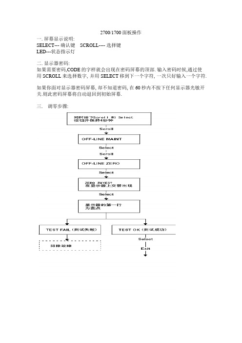
2700/1700面板操作一. 屏幕显示说明:SELECT--- 确认键 SCROLL---- 选择键LED---状态指示灯二. 显示器密码:如果需要密码,CODE的字样就会出现在密码屏幕的顶部. 输入密码时候,通过使用SCROLL来选择数字, 并用SELECT移到下一个字符, 一次只好输入一个字符.如果你面对显示器密码屏幕, 却不知道密码, 在60秒内不按下任何显示器光敏开关.则此密码屏幕将自动退回到初始屏幕.三. 调零步骤:四. 显示器回路测试:五. 显示器查看报警:LED指示灯状态及报警查看六. 管理累积量和库存量:七: 测量单位设置:SELECT+SCROLL 按4秒SEE ALARM [SCROLL]OFFLINE MAINTAIN [SELECT] [SCROLL]CONFIG [SELECT] MASS [SELECT]可以按SCROLL选择你要的单位选定后按SELECT按SCROLL直到出现EXIT [SELECT]体积单位和密度单位设置和上述步骤相同八量程设置(LRV URV)[SELECT+SCROLL] 按4秒SEE ALARM [SCROLL]OFFLINE MAINTAIN [SELECT] 继续按SCROLL直到出现MAO1 [SELECT] SRC MAO1 [SELECT]MFLOW [SELECT] SRC MAO1 [SCROLL]4 MAO1 输入最小量程 [SCROLL+SELECT] 4 MAO1[SCROLL] 20 MAO1 [SELECT] 输入最大量程 [SELECT+SCROLL] 20 MAO1 [SCROLL] EXIT 按SELECT退出.其他量程设置和上述步骤相同.NOTE: SELECT+SCROLL 表示两个键同时按下九: 报警代码和解决办法。
- 1、下载文档前请自行甄别文档内容的完整性,平台不提供额外的编辑、内容补充、找答案等附加服务。
- 2、"仅部分预览"的文档,不可在线预览部分如存在完整性等问题,可反馈申请退款(可完整预览的文档不适用该条件!)。
- 3、如文档侵犯您的权益,请联系客服反馈,我们会尽快为您处理(人工客服工作时间:9:00-18:30)。
罗斯蒙特硅表说明书
罗斯蒙特硅表是一种广泛应用于科学实验和工业生产中的仪器,
它以其精准的测量和高可靠性而被广泛认可。
本说明书将为您介绍罗
斯蒙特硅表的结构、使用方法、注意事项以及常见故障处理方法,希
望能帮助您更好地使用罗斯蒙特硅表。
一、结构
罗斯蒙特硅表主要由表盘、刻度盘、表壳、转轴、测量弹簧以及
指针等组成。
表盘通常采用不锈钢材质,刻度盘上刻有精确的刻度,
用于读取测量结果。
表壳由坚固的材料制成,起到保护硅表内部结构
的作用。
转轴连接表盘和指针,使指针能够旋转并指示测量结果。
测
量弹簧是罗斯蒙特硅表的核心部件,能够根据外力大小的变化产生相
应的变形,从而实现测量功能。
二、使用方法
1.预备工作:在使用罗斯蒙特硅表之前,需要检查表盘和刻度盘,确保其完好无损。
同时需要检查指针是否灵活,转轴是否正常工作。
2.测量:将需要测量的物体或介质放置在硅表下方的测量台上,
确保其平稳稳定。
然后根据需要选择合适的测量范围,将指针对准刻
度盘上的刻度,并记录测量结果。
3.注意事项:在使用罗斯蒙特硅表时,需要注意以下几点:
a.确保测量环境稳定,避免外力对测量结果的影响。
b.使用过程中避免将硅表置于高温、潮湿或强磁场等环境中,以
免影响其准确性和使用寿命。
c.使用后及时清洁表盘和刻度盘,保持其清晰可读,延长使用寿命。
d.定期进行校准,以确保测量结果的准确性和可靠性。
4.故障处理:如果发现罗斯蒙特硅表出现无法正常工作的情况,
可以尝试以下故障处理方法:
a.检查指针是否卡住或松动,如果松动可以适当调整转轴来修复。
b.检查测量弹簧是否弯曲或损坏,如果损坏需要更换新的测量弹簧。
c.检查表盘上的刻度是否清晰可读,如果不清晰可以用湿布擦拭或使用适量的清洁剂清洁。
d.如果以上方法无法解决问题,建议联系售后服务人员或专业维修人员进行进一步检修和修复。
通过本说明书的介绍,相信您对罗斯蒙特硅表的结构、使用方法以及常见故障处理方法有了更深入的了解。
使用罗斯蒙特硅表时,请务必严格按照说明书进行操作,并注意安全使用,以确保测量结果的准确性和操作的顺利进行。
祝您使用愉快!。