哈希ez1000硅表说明书
DS1000Z-E系列数字示波器说明书

DS1000Z-E series is a high-performance and economic digital oscilloscope designed for the designing, debugging and educational requirements of the mainstream digital oscilloscope market. This manual takes DS1202Z-E asan example to introduce DS1000Z-E series.Analog channel bandwidth: 200 MHz (DS1202Z-E): 100 MHz (DS1102Z-E) 2 analog channelsReal-time sample rate up to 1 GSa/s Memory depth up to 24 Mpts(Std.)Up to 30,000 wfms/s waveform capture rateUp to 60,000 frames hardware real-time waveform recording and playback functionsInnovative "UltraVision" technologyVarious trigger and bus decoding functionsLow noise floor, vertical scale range: 500 uV/div to 10 V/div Various interfaces: USB Host&Device, LAN (LXI), AUX Novel and delicate industrial design, easy to use7-inch WVGA (800x480) TFT LCD, intensity graded color display2DS1000Z-E Series Digital OscilloscopeDeep Memory Depth (up to 24 Mpts, std.)Higher Waveform Capture Rate (up to 30,000 wfms/s)Real-time Waveform Recording&Playback (up to 60,000 frames) Intensity Graded Color DisplayInnovative UltraVision Technology(Analog Channel)Product Dimensions: Width×Height×Depth=313.1 mm×160.8 mm×122.4 mm Weight: 2.9 kg ± 0.2 kg(Without Package)7-inch WVGA (800X480) TFT display,intensity graded color display2 analog channelsExternal trigger input channel3UltraVision: deep memory (up to 24 Mpts, std.)UltraVision: up to 30,000 wfms/s waveform capture rateUltraVision: waveform recording and playbackfunctionsUltraVision: intensity graded color displayA variety of trigger functionsSerial bus trigger and decoding functions (RS232/UART, I2C, SPI)450 Ω impedanceadapter (2 W, 1 GHz)RIGOL Passive ProbesRIGOL Active & Current ProbesRIGOLProbes and Accessories Supported by DS1000Z SeriesRP1001CCurrent ProbeBW: DC to 300 kHz Max. input DC: ±100 A,AC P-P: 200 A,AC RMS: 70 ACompatibility: all RIGOL scopes.RP1002CCurrent ProbeBW: DC to 1 MHz Max. input DC: ±70 A,AC P-P: 140 A,AC RMS: 50 ACompatibility: all RIGOL scopes.RP1003CCurrent ProbeBW: DC to 50 MHz Max. inputAC P-P: 50 A (Noncontinuous),AC RMS: 30 ACompatibility: all RIGOL scopes.Must order RP1000P power supply.RP1004CCurrent ProbeBW: DC to 100 MHz Max. inputAC P-P: 50 A (Noncontinuous),AC RMS: 30 ACompatibility: all RIGOL scopes.Must order RP1000P power supply.RP1005CCurrent ProbeBW: DC to 10 MHz Max. inputAC P-P: 300 A (Noncontinuous), 500 A (@pulse width ≤30 us),AC RMS: 150 ACompatibility: all RIGOL scopes.Must order RP1000P power supply.RP1000PPower SupplyPower supply for RP1003C,RP1004C and RP1005C, support 4 channels.RP1025DHighVoltageDifferentialProbeBW: 25 MHzMax. Voltage ≤1400 VppCompatibility: all RIGOL scopes.RP1050DHighVoltageDifferentialProbeBW: 50 MHzMax. Voltage ≤7000 VppCompatibility: all RIGOL scopes.RP1100DHighVoltageDifferentialProbeBW: 100 MHzMax. Voltage ≤7000 VppCompatibility: all RIGOL scopes.High Voltage ProbeDC to 150 MHzDC+AC Peak: 18 kV CAT II AC RMS: 12 kV CAT II Compatibility: all RIGOL scopes.RP1018HRT50JAdapterPVP2150High Z Probe1X: DC to 35 MHz 10X: DC to 150 MHzCompatibility: all RIGOL scopes.PVP3150HighZ Probe1X: DC to 20 MHz 10X: DC to 150 MHzCompatibility: all RIGOL scopes.PVP2350High Z Probe1X: DC to 35 MHz 10X: DC to 350 MHz Compatibility:all RIGOL scopes.RP3500AHigh Z ProbeDC to 500 MHz Compatibility:all RIGOL scopes.RP1300HHigh Voltage Probe DC to 300 MHzCAT I 2000 V (DC+AC), CAT II 1500 V (DC+AC) Compatibility: all RIGOLscopes.RP1010HHighVoltageProbeDC to 40 MHzDC: 0 to 10 kV DC,AC: pulse ≤20 kVp-p,AC: sine wave ≤7 kVrmsCompatibility: all RIGOL scopes.SpecificationsAll the specifications are guaranteed except parameters marked with “Typical” and the oscilloscope needs to operate for more than 30 minutes under the specified operation temperature.SampleSample Mode Real-time sampleReal-time Sample Rate 1 GSa/s (single-channel), 500 MSa/s (dual-channel)Peak Detect 4 nsAveraging After all the channels finish N samples at the same time, N can be 2, 4, 8, 16, 32, 64, 128, 256, 512 or 1024High Resolution12 bits (max.) Interpolation Sin(x)/xMemory Depth 24 Mpts (single-channel), 12 Mpts (dual-channel)InputNumber of Channels 2 analog channelsInput Coupling DC, AC or GNDInput Impedance (1 MΩ±1%) || (15 pF±3 pF) Probe AttenuationCoefficient0.01X to 1000X, in 1-2-5 stepMaximum Input Voltage (1 MΩ)CAT I 300 Vrms, CAT II 100 Vrms, transient overvoltage 1000 VpkHorizontalTimebase Scale 2 ns/div to 50 s/div Maximum RecordLength24 Mpts Timebase Accuracy[1]≤±25 ppmClock Drift≤±5 ppm/yearMaximum Delay Range Negative delay: ≥1/2 screen width Positive delay: 1 s to 500 sTimebase Mode YT, XY, RollNumber of X-Ys1Waveform CaptureRate[2]30,000 wfms/s (dots display) Zero Offset±0.5 div*minimum timebase scale VerticalBandwidth (-3 dB) DS1202Z-E: DC to 200 MHz DS1102Z-E: DC to 100 MHzSingle-shot Bandwidth DS1202Z-E: DC to 200 MHz DS1102Z-E: DC to 100 MHzVertical Resolution8 bitsVertical Scale(Probe ratio is 1X)500 uV/div to 10 V/divOffset Range (Probe ratio is 1X)500 uV/div to 499 mV/div: ±2 V 500 mV/div to 10 V/div: ±100 VBandwidth Limit[1]20 MHzLow FrequencyResponse(AC Coupling, -3 dB)≤5 Hz (on BNC)Calculated Rise Time[1]DS1202Z-E: 1.75 ns DS1102Z-E: 3.5 nsDC Gain Accuracy <10 mV: ±4% full scale ≥10 mV: ±3% full scaleDC Offset Accuracy±0.1 div ± 2 mV ± 1% offset value Channel to ChannelIsolationDC to maximum bandwidth: >40 dB5MeasureCursor ManualmodeVoltage deviation between cursors(△V)Time deviation between cursors(△T)Reciprocal of △T (Hz) (1/△T) TrackmodeVoltage and time values of thewaveform pointAutomodeAllow to display cursors duringauto measurementAuto Measurement Period, Frequency, Rise Time, Fall Time, Positive Pulse Width, Negative Pulse Width, Positive Duty Cycle, Negative Duty Cycle, tVmax, tVmin, Positive Rate, Negative Rate, Delay 1→2, Delay 1→2, Phase 1→2, Phase 1→2, Maximum, Minimum, Peak-Peak Value, Top Value, Bottom Value, Amplitude, Upper Value, Middle Value, Lower Value, Average, Vrms, Overshoot, Pre-shoot, Area, Period Area, Period Vrms, VarianceNumber ofMeasurementsDisplay 5 measurements at the same time. MeasurementRangeScreen or cursorMeasurement Statistic Average, Max, Min, Standard Deviation,Number of MeasurementsCounterHardware 6-digit counter (channels areselectable)Math OperationWaveform OperationA+B, A-B, A×B, A/B, FFT, A&&B, A||B,A^B, !A, Intg, Diff, Sqrt, Lg, Ln, Exp, Abs,FilterFFT WindowRectangle, Hanning, Blackman,Hamming, Flat Top, TriangleFFT Mode Trace, MemoryFFT Display Half, FullFFT Vertical Scale dB/dBm, VrmsFilterLow Pass Filter, High Pass Filter, BandPass Filter, Band Stop FilterNumber of Buses forDecoding2Decoding Type Parallel, RS232/UART, I2C, SPIDisplayScreen Type7.0-inch TFT LCD displayDisplay Resolution800 horizontal × RGB × 480 vertical pixelDisplay Color16 million color (24-bit true color)Persistence TimeMin, 100 ms, 200 ms, 500 ms, 1 s, 5 s, 10s, InfiniteDisplay Type Dots, VectorI/OStandard PortsUSB Host, USB Device, LAN, Aux Output(TrigOut/PassFail)The recommended calibration interval is 18 months.67Note [1]: Typical.Note [2]: Maximum value. 50 ns, single-channel mode, dots display, auto memory depth.Note [3]: Supporting legs and handle folded, knob height included.Note [4]: Standard configuration.WarrantyThree -year warranty, excluding probes and accessories.Standard SoftwareUltra SigmaUltra ScopeReal-time monitoring of waveform and status;supports multi-instrument and multi-window display With virtual panel featureSupports multi-interface remote controlRIGOL general PC software platformMulti-instrument and multi-interface resource management With SCPI remote command toolPCX01100-2020-04RIGOL ® is the trademark of RIGOL TECHNOLOGIES CO., LTD. Product information in this document subject to update without notice. For the latest information about RIGOL 's products, applications and services, please contact local RIGOL Channel Partners or access RIGOL official website: HEADQUARTERRIGOL TECHNOLOGIES CO., LTD.No.8 Keling Road, New District,Suzhou, JiangSu,P .R.China Tel:+86-400620002Email:**************EUROPERIGOL TECHNOLOGIES EU GmbH Lindbergh str. 482178 Puchheim GermanyTel: +49-89/89418950Email:*********************NORTH AMERICARIGOL TECHNOLOGIES, USA INC.8140 SW Nimbus Ave.Beaverton, OR 97008Tel: +1-877-4-RIGOL -1Fax: +1-877-4-RIGOL -1Email:**************JAPANRIGOL TECHNOLOGIES JAPAN, LLC MJ Bldg. 3F, 1-7-4 Minato, Chuou-ku, Tokyo, Japan 104-0043Tel: +81-3-6262-8932Fax: +81-3-6262-8933Email:********************。
9210硅表中文操作手册

硅分析仪9210 指导手册致读者本册中包含的信息内容是尽可能与印刷时仪表的版本相符合的。
如果你在使用仪表时客观地发现其性能与本册叙述有不相符之处,也许是你的手册已经过期。
如果是此种情况,请立即与你的当地Polymetron代理商联系如果不按照生产厂家的规定和要求的方法使用仪表,将会损坏仪表正常的质量保证Polymetron保留对本册中所述仪表的软,硬件进行修改和更换的权力谢谢合作 !621=092=010 Rev. B Polymetron S.A.S. 02/2003安全警告请在拆包,安装或运行仪表前将手册完整的阅读一遍。
特别要注意所有标示"危险"和"警告" 的部分。
否则会对操作者造成严重伤害或导致设备的损坏为确保设备不受损害,不要采取任何不符合手册要求的方法使用和安装设备关于危险信息:由于存在着多种危险情况,本册将使用符号字(危险,警告,注意)来对应于情况的危险程度危险提示一个潜在的或危急的危险情况。
若不避免会导致重大伤亡警告标示一个潜在的也许会导致某种程度伤害的危险情况注意需要特别强调的信息预先警告标签请阅读所有附在仪表上的标签。
如果不遵守标签上的警告会导致人身伤害或造成设备损害仪表上的这个符号,要求操作者参照操作手册运行仪表和学习安全信息仪表上的这个符号,标示出接地保护的接地点仪表上的这个符号,显示出需要戴防目罩电源连接,见18页仪表电源接线,见15页试剂的制备,见21页维护,见第7页和A2维护定期检查仪表的完整电气连接和仪表系统的保护,进行所有必要的检测来消除故障隐患服务和维修用户不要自行修理仪表的元件。
只有Polymetron的工程师及授权代理商有权对系统进行维修,并应该使用由厂家正式批准所采用的元件。
任何违背这一原则试图进行仪表维修的行动可能会引发对仪表的损坏和人身的伤害。
它还会导致厂家质量保证的失效并危及仪表的正常工作以及仪表的电气完整性或CE标准如果你在仪表的安装、开机和使用中有任何可能的问题,请与你的当地供应商直接联系。
硅表中文手册

Chempure++ 1056 在线硅酸根分析仪安装使用说明书特别说明特别说明Emerson Process Management (Rosemount Analytical) 设计、生产和测试过的各种产品均符合许多国家和国际标准,仪器的性能经得起各项相应的产品性能测试。
能够在正常的技术规范内,长期连续运行完好。
在安装、使用与维护Emerson Process Management (Rosemount Analytical) 分析仪器时,要严格执行以下的说明,否则,将可能导致人员伤亡、财产损失、仪器设备损坏和相关的质量承诺失效。
在安装、使用与维护分析仪器设备之前,如果有不能充分理解的地方,请与Emerson Process Management (Rosemount Analytical)。
为了今后对分析仪器进行正确的安装操作与维护,,Emerson Process Management (Rosemount 为了今后对分析仪器进行正确的安装、、操作与维护。
,将所有与仪器产品有关的电缆连接到相应的电源上。
为了确保分析仪器能够表现出理想的性能,安装、调试、操作和维护等工作必须由有资质的专业人员进行。
当需要向厂方购买更换的零配件时,更换工作要由Emerson Process Management (Rosemount Analytical) 指定的有资质的专业人员来进行。
未经授权的零部件替代品会影响产品的性能,并破坏系统操作的安全性,如火灾和电击危险。
言前 言编制该说明书的目的在于提供一份书面材料,以便用户对Chempure++ 1056在线硅酸根分析仪的组件、功能、性能、安装、使用和维护有一个全面的了解。
Chempure++ 1056在线硅酸根分析仪是Emerson Process Management (Rosemount Analytical) 最新推出的产品,可以广泛地应用在电力、石化等领域,主要用来连续监测发电厂锅炉水、锅炉给水、软化水、凝结水及蒸汽冷凝水等。
XIA-MI1000编程手册

a) 百分比上限:设定百分比最大值(0~100) b) 百分比下限:设定百分比最小值(0~100)
计算方法:
计算检查窗口内部符合亮度和颜色设定范围内的像素组成的最大连通区域的最小外接 矩形。并计算该外接矩形面积与检查窗口面积的百分比。百分比的结果符合判定参数范围时, 判定结果为 OK。反之,判定结果为 NG。
Range
计算参数: a) X 邻域:设定 X 方向做均值运算的像素个数 b) Y 邻域:设定 Y 方向做均值运算的像素个数 判定参数: a) 上限:亮度最大值(0~255) b) 下限:亮度最小值(0~255) 计算方法: 先 X 邻域和 Y 邻域做均值运算后,再计算检查窗口内部像素亮度最大值。结果符合判 定参数的范围时,判定结果为 OK。反之,判定结果为 NG。
易用性
机器采用 Microsoft Windows XP 操作系统。强劲的功能,满足用户全面的需求。
高精度高速度
机器采用 2M 像素工业相机,在 20u 时 FOV 区域大小为:32mm X 24mm。机器可以 在 1sec 内完成对 4/5FOV 的拍摄和检测。通过对相机的调整,可以将最高分辨率升至 10um。
Mean
计算参数: 无 判定参数: a) 上限:亮度最大值(0~255) b) 下限:亮度最小值(0~255) 计算方法: 计算检查窗口内部像素亮度的平均值。结果符合判定参数的范围时,判定结果为 OK。 反之,判定结果为 NG。
Max
计算参数: a) X 邻域:设定 X 方向做均值运算的像素个数 b) Y 邻域:设定 Y 方向做均值运算的像素个数 判定参数: a) 上限:亮度最大值(0~255) b) 下限:亮度最小值(0~255) 计算方法: 先 X 邻域和 Y 邻域做均值运算后,再计算检查窗口内部像素亮度最大值。结果符合判 定参数的范围时,判定结果为 OK。反之,判定结果为 NG。
哈希DR800系列操作说明CH

48440-18DR/820, DR/850, and DR/890便携式数据记录比色计操作手册© Hach Company, 1997-1999. All rights reserved. Printed in the U.S.A. dd/dp 6/02/97 1edrev. 5, 8/99目录安全性信息规格使用说明第一章一般描述1.1 仪器概述1.2 仪器开箱1.2.1 标准附件1.2.2 可选附件1.3 键位描述1.4 显示屏功能和数字模式1.5 图标和显示屏第二章仪器安2.1 电池安装2.2 开机2.3 设置日期和时间2.3.1 输入正确日期2.3.2 输入正确时间2.4 样品池插入2.5 样品池适配器安装2.5.1 16-mm COD/Test ‘N Tube 样品瓶适配器的使用2.5.2 免疫测定管适配器的使用2.6 仪器遮光罩的使用第三章仪器操作3.1 菜单3.1.1 SETUP 菜单3.1.2 Recall 菜单3.2 分析操作3.2.1 设置3.2.2 样品准备3.2.3 仪器调零3.2.4 测定已准备好的样品3.2.5 选择合适的化学式3.2.6 定时器使用3.2.6.1 手动模式使用定时器3.2.6.2 停止使用定时器3.3 空白样校准3.4 调整标准曲线3.5 程序方法的使用3.6 质量保证第四章创建用户自建程序4.1用户自建程序4.2 标准曲线4.3 用户自建程序测量化学漂白试剂4.4 创建新的用户程序4.5 编辑用户自建程序4.6删除用户自建程序第五章数据调出和存储5.1 调查数据5.2 删除全部存储数据第六章打印和数据传输6.1 数据传输适配器6.1.1 连接数据传输适配器6.2 RS232 联接6.2.1 打印机设置和使用6.2.2 连接到个人计算机6.3 发送数据到打印机或计算机6.3.1 发送当前数据6.3.2 发送调出数据6.3.3 发送全部存储数据第七章维护7.1 清洗比色计7.1.1 清洗数据传输适配器7.1.2 样品池7.2 零件更换7.2.1更换电池第八章发现并修理故障8.1 简介8.1.1 故障代码8.1.2 报警8.1.3 超量程8.1.4 低电量附录A 参数和量程一般信息可更换部件质量保证证明安全性信息在开箱、安装和操作仪器以前请完整阅读本手册,特别要注意所有的危险警示和注意事项。
HACH 哈希pH-ORP
GLI-P33-C
仪器操作手册
第2章
菜单结构
2.1 显示主要分支选择屏…………………………………………….………….32 2.2 显示顶级菜单屏……………………………………...……………….….…33 2.3 显示子菜单屏…………………………………….….………………….…..34 2.4 调整编辑/选择屏值…………………………………..……………………..34 2.5 输入(存储)编辑/选择屏值/备选值…………………..…………………….34
2. 分析仪按出厂设置来使用 GLI 5 线差分法 pH 传感器。当使用一个常规复合电极时, 用户必须改变传感器类型(见第三部分的第 3.2 节,副标题为“选择传感器类型”)。
3. 分析仪的出厂设置使用安装在所有 GLI 差分传感器上的 NTC 300 欧姆温度元件进行 自动温度补偿(除了 6006P4-2000 型高纯水 pH 传感器系统,其使用 Pt 1000 欧姆 RTD)。当使用一个带不同温度元件的传感器或用户试图使用手动固定温度补偿,则 用户必须改变温度元件类型(见第三部分的第 3.2 节,副标题为“选择温度元件类型”)。
9. 在屏幕显示
后,从第一个缓冲液中取走传感器,并放入干净水中
清洗,随后将传感器浸没在第二个缓冲液中(通常 pH 为 4)。
10. 随后按 ENTER(进入)键确认。当屏幕显示
时,分析仪等待 pH
和温度信号稳定以及测量缓冲液值和自动校准该点。随后,屏幕出现
9610硅表中文整合版操作手册

DOC023.97.80246Polymetron 9610sc SiO205/2013, Edition 1InstallationInstallationInstalaciónInstalação安装設置설치การติดตัง目录规格第 74基本信息第 75安装第 78规格产品规格如有变化,恕不另行通知。
表 1 一般技术指标表 1 一般技术指标(续)1标准立方英尺/小时,74中文表 2 测量规格1精度只取决于 Hach 供应的试剂。
基本信息对于因本手册中的任何不足或遗漏造成的直接、间接、特别、附带或结果性损失,制造商概不负责。
制造商保留随时更改本手册和手册中描述的产品的权利,如有更改恕不另行通知或承担有关责任。
修订版可在制造商的网站上找到。
安全信息请在拆开本设备包装、安装或使用本设备前,完整阅读本手册。
特别要注意所有的危险警告和注意事项。
否则,可能会对操作者造成严重的人身伤害,或者对设备造成损坏。
确保设备提供的保护没有受损。
请勿以本手册指定方式之外的其它方式使用或安装本设备。
危险信息使用警告标签请阅读贴在仪器上的所有标签和标记。
如未遵照这些安全标签的指示操作,则可能造成人身伤害或仪器损坏。
仪器上如有标志,则手册中会提供危险或小心说明。
中文 75加拿大无线电干扰产生设备法规(Canadian Radio Interference-Causing Equipment Regulation),IECS-003,A 类:制造商支持测试记录留存。
此 A 类数字设备符合加拿大干扰产生设备法规的所有要求。
Cet appareil numérique de classe A répond à toutes les exigences de laréglementation canadienne sur les équipements provoquant desinterférences.FCC 第 15 部分,“A”类限制制造商支持测试记录留存。
美高加索 Gemini 1000 2000 计数器 计时器说明书
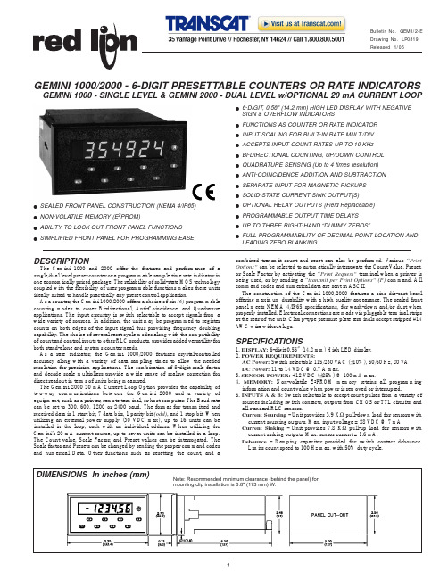
!SEALED FRONT PANEL CONSTRUCTION (NEMA 4/IP65)!NON-VOLATILE MEMORY (E 2PROM)!ABILITY TO LOCK OUT FRONT PANEL FUNCTIONS !SIMPLIFIED FRONT PANEL FOR PROGRAMMING EASE !6-DIGIT, 0.56" (14.2 mm) HIGH LED DISPLAY WITH NEGATIVESIGN & OVERFLOW INDICATORS!FUNCTIONS AS COUNTER OR RATE INDICATOR!INPUT SCALING FOR BUILT-IN RATE MULT./DIV.!ACCEPTS INPUT COUNT RATES UP TO 10 KHz!BI-DIRECTIONAL COUNTING, UP/DOWN CONTROL!QUADRATURE SENSING (Up to 4 times resolution)!ANTI-COINCIDENCE ADDITION AND SUBTRACTION!SEPARATE INPUT FOR MAGNETIC PICKUPS!SOLID-STATE CURRENT SINK OUTPUT(S)!OPTIONAL RELAY OUTPUTS (Field Replaceable)!PROGRAMMABLE OUTPUT TIME DELAYS!UP TO THREE RIGHT-HAND “DUMMY ZEROS”!FULL PROGRAMMABILITY OF DECIMAL POINT LOCATION ANDLEADING ZERO BLANKING DESCRIPTION The Gemini 1000 and 2000 offer the features and performance of asingle/dual level preset counter or a programmable sample time rate indicator inone economically priced package. The reliability of solid-state MOS technologycoupled with the flexibility of user programmable functions makes these unitsideally suited to handle practically any preset control application.As a counter, the Gemini 1000/2000 offers a choice of six (6)programmablecounting modes to cover Bi-directional, Anti-Coincidence, and Quadratureapplications. The input circuitry is switch selectable to accept signals from awide variety of sources. In addition, the unit may be programmed to registercounts on both edges of the input signal thus providing frequency doublingcapability. The choice of several reset cycle modes along with the compatibilityof count and control inputs to other RLC products, provides added versatility forboth stand-alone and systems counter needs.As a rate indicator, the Gemini 1000/2000 features crystal-controlledaccuracy along with a variety of data sampling times to allow the neededresolution for precision applications. The combination of 5-digit scale factorand decade scale multipliers provide a wide range of scaling correction fordirect readout in terms of units being measured.The Gemini 2000 20 mA Current Loop Option provides the capability oftwo-way communications between the Gemini 2000 and a variety ofequipment, such as a printer, remote terminal, or host computer. The Baud ratecan be set to 300, 600, 1200 or 2400 baud. The format for transmitted andreceived data is 1 start bit, 7 data bits, 1 parity bit (odd), and 1 stop bit. Whenutilizing an external power supply (30 VDC max), up to 16 units can beinstalled in the loop, each with an individual address. When utilizing theGemini’s 20 mA current source, up to seven units can be installed in a loop.The Count value, Scale Factor, and Preset values can be interrogated. TheScale factor and Presets can be changed by sending the proper command codesand numerical Data. Other functions such as resetting the count, and a combined transmit count and reset can also be performed. Various “Print Options”can be selected to automatically interrogate the Count Value, Preset,or Scale Factor by activating the “Print Request”terminal when a printer is being used, or by sending a “transmit per Print Options”(P)command. All command codes and numerical data are sent in ASCII.The construction of the Gemini 1000/2000 features a zinc die-cast bezel offering maximum durability with a high quality appearance. The sealed front panel meets NEMA 4/IP65 specifications, for wash-down and/or dust when properly installed. Electrical connections are made via pluggable terminal strips at the rear of the unit. Clamp-type pressure plate terminals accept stripped #14AWG wire without lugs.SPECIFICATIONS1. DISPLAY:6-digit 0.56" (14.2 mm) High LED display.2. POWER REQUIREMENTS:AC Power:Switch selectable 115/230 V AC (±10%), 50/60 Hz, 20 V A DC Power:*****************.3. SENSOR POWER:+12 VDC (±25%) @ 100 mA max.4. MEMORY:Non-volatile E 2PROM memory retains all programming information and count value when power is removed or interrupted.5.INPUTS A &B:Switch selectable to accept count pulses from a variety of sources including switch contacts, outputs from CMOS or TTL circuits, and all standard RLC sensors.Current Sourcing - Unit provides 3.9 K Ωpull-down load for sensors with current sourcing outputs. Max. input voltage = 28 VDC @ 7 mA.Current Sinking - Unit provides 7.8 K Ωpull-up load for sensors with current sinking outputs. Max. sensor current = 1.6 mA.Debounce - Damping capacitor provided for switch contact debounce.Limits count speed to 100 Hz max. with 50% duty cycle.GEMINI 1000/2000 - 6-DIGIT PRESETTABLE COUNTERS OR RATE INDICATORSGEMINI 1000 - SINGLE LEVEL & GEMINI 2000 - DUAL LEVEL w/OPTIONAL 20 mA CURRENT LOOPPROGRAMMABLE FUNCTIONSUNIT PERSONALITYFunctions as a Counter and Rate Indicator.PRESET(S)Range 0 to ±999999SCALE FACTORS5-digit input scaling, Range 0.0000 to ±5.9999.SCALE MULTIPLIERMultiplies the contents of the 9-digit internal counter by a factor of 1, 0.1, 0.01, or 0.001 to view the desired number of significant digits on the 6-digit display. COUNTING MODESCount with InhibitCount with Up/Down Control2-Input Anti-Coincidence Add2-Input Anti-Coincidence Add/SubtractQuadratureQuadrature X4RESET ACTIONReset-to-Zero:Output activates when count equals the preset value. Counter returns to zero when reset.Reset-to-Preset:Output activates when count equals zero. Counter returns to preset value when reset.RESET MODESManual ResetAutomatic Reset at PresetAutomatic Reset after Output Time DelayNote: Manual reset via front panel pushbutton or remote “RST.” terminal can be programmed for momentary or maintained action. Front panel reset may be disabled by a switch at the rear of the unit.SELF-TESTPerforms a complete check on the display and output circuitry along with a functional check on the CPU. Self-test is non-destructive and may be performed during a process without losing counts.FREQUENCY DOUBLINGRegisters counts on both edges of input signal.DECIMAL POINT & LEADING ZERO BLANKINGDecimal point programmable to desired location. Leading zero blanking, when selected, begins with second digit to the left of the decimal point. RIGHT-HAND DUMMY ZEROSUp to three non-functional zeros may be placed on the least significant end of the display.OUTPUT TERMINATION MODESTerminate at “other” Output Start (Gemini 2000 only)Terminate at “other” Output End (Gemini 2000 only)Terminate at Manual ResetTerminate at Manual Reset EndTerminate after Time DelayBoundaryFor positive preset value: Output terminates when Display is less than Preset.For negative preset value: Output terminates when Display is greater than Preset (i.e. more positive).Note: In any of the above modes, the unit may be programmed for “Reverse Phase” operation which complements the logic state of the output. OUTPUT TIME DELAYProgrammable from 0.01 to 599.99 seconds. Accurate to ±(0.01% + 10 msec.). SAMPLE TIME MULTIPLIERMultiplies the basic one-second data sampling time by 1, 2, 5, 10,20, or 50. Accurate to ±0.01%.FRONT PANEL LOCKOUT MODESWhen the “Program Disable” control input is activated, the ability to change front panel programmed functions will be prevented as per the following modes: Complete Front Panel DisablePreset(s)Enabled OnlyScale Factor Enabled OnlyBoth Preset(s)and Scale Factor EnabledNote: Reset may be enabled or disabled in any of the above modes.SPECIFICATIONS (Cont’d)Lo Bias- Input trigger levels V IL= 1.5 V max., V IH= 3.75 V.Hi Bias- Input trigger levels V IL= 5.5 V max., V IH= 7.5 V.Note: Bias levels given are ±10% @ 12 VDC. They vary proportionally with sensor supply voltage.6. MAGNETIC PICKUP INPUT:Sensitivity- 150 mV peak nominalHysteresis - 100 mV nominalInput Impedance- 26.5 KΩ@ 60 Hz nominalMaximum Input Voltage- ±50 V peak7. MAXIMUM COUNT RATES:Uni- or Bi-Directional Modes:9 KHz; 8 KHz (X2)2-Input Anti-Coincidence Modes:5 KHz; 4 KHz (X2)Quadrature Modes:5 KHz; 4 KHz (X2 or X4)Rate Indicator:10 KHz; 8 KHz (X2)8.CONTROL INPUTS:Reset- Active Low (V IL= 1.5 V max.) internally pulled up to +12 VDC(I SNK= 3 mA), response time = 10 msec (typical).Program Disable- Active Low (V IL= 1.5 V max.), internally pulled up to +5 VDC (I SNK= 1 mA).Print Request- (GEM2 only)Active Low (V IL= 1.5 V max.) internally pulled up to +5 VDC (I SNK= 1 mA).9. SERIAL COMMUNICATIONS (Optional, Gemini 2000 only):Type- Bi-directional 20 mA current loop, 20 mA source provided. (Powers up to seven units in a loop with internal current source.) Baud Rate- Programmable 300 to 2400.Maximum Address- 16 units (0 to 15). (Actual number in a single loop is limited by serial hardware specifications.)Data Format- 10 bit frame, Odd parity (one start bit, 7 data bits, one odd parity bit, and one stop bit.)Serial Hardware Specifications-SO- Output Transistor Rating: V MAX= 30 VDC, V SA T= 1 V MAX@ 20 mA. (Can address 16 units in a loop)SI- Input Diode Rating: V F= 1.25 V TYP; 1.5 V MAXNote: The compliance voltage rating of the source must be greater than the sum of the voltage drops around the loop.10. OUTPUT(S):Solid-State- Current sinking NPN Open Collector Transistor(s). I SNK= 100 mA max. V OH= 30 VDC max. (Internal Zener Diode Protected). V OL=1 VDC max @ 100 mARelay(s)- Mounted on a field-replaceable P.C. board. Form C contacts rated5 amps @ 120/240 V AC, 28 VDC (resistive load), 1/8 H.P. @ 120 V AC(inductive load). The operate time is 5 msec nominal and the release time is 3 msec nominal.Relay Life Expectancy- 100,000 cycles at max. rating. (As load level decreases, life expectancy increases.)Programmable Timed Outputs(s)- The timed output(s)can be set from0.01 to 599.99 seconds, ±(0.01% + 10 msec).11.CERTIFICATIONS AND COMPLIANCES:SAFETYIEC 1010-1, EN 61010-1: Safety requirements for electrical equipment for measurement, control, and laboratory use, Part 1.IP65 Enclosure rating (Face only), IEC 529Type 4 Enclosure rating (Face only), UL50ELECTROMAGNETIC COMPATIBILITY:Notes:1. Metal bezel of unit connected with ground lead from rear bezel screw tometal mounting panel.2. When the unit is DC powered, a power line filter (RLC# LFIL0000 orequivalent) was installed, so as not to impair the function of the unit.Refer to the EMC Installation Guidelines section of the manual for additional information.Immunity to EN 50082-2Electrostatic discharge EN 61000-4-2Level 2; 4 Kv contact 1Level 3; 8 Kv air Electromagnetic RF fields EN 61000-4-3Level 3; 10 V/m80 MHz - 1 GHzFast transients (burst)EN 61000-4-4Level 4; 2 Kv I/O2 Kv power 2RF conducted interference EN 61000-4-6Level 3; 10 V/rms150 KHz - 80 MHzEN 61000-4-8Level 4; 30 A/m Emissions to EN 50081-2RF interference EN 55011Enclosure class APower mains class A Power frequency magnetic fields12. ENVIRONMENTAL CONDITIONS :Operating Temperature : 0 to 50°CStorage Temperature : -40 to 80°COperating and Storage Humidity : 85% max. relative humidity (non-condensing) from 0 to 50°C.Altitude : Up to 2000 meters13. CONSTRUCTION :Metal die-cast bezel, plastic case. This unit is rated for NEMA 4/IP65 indooruse. Installation Category II, Pollution Degree 214. WEIGHT : 2.1 lbs. (0.9 kg)PROGRAMMING The Gemini 1000/2000 input circuit set-up is programmed using DIP switches on the rear of the unit. All other functions are programmed through the front panel pushbuttons.To program or interrogate a function, the user first enters a two-digit function code. The unit will then display that function code along with a single-digit representing the present mode of operation. Programming changes are made by changing the single-digit mode identifier.EXAMPLE:The function code representing the “Unit Personality” is 41. The mode identifiers for this function are:Counter (1) and Rate Indicator (2).To interrogate the Unit Personality, Press “41”:Unit displays function code along with mode identifier(Rate Indicator).To change the Unit Personality to Counter mode,Press “1”:Unit displays the new mode identifier (Counter).Press “E”:Unit enters new mode and returns display to the present count value.The most commonly used functions, Preset (s)and Scale Factor, are initialized through single front panel pushbuttons rather than a two-digit function code.Pressing the “1” or “3” pushbuttons will immediately display the current Preset or Scale Factor value for the selected display. To change any digit, the user presses the pushbutton directly below that particular digit, which is then scrolleduntil the desired value is obtained. Each digit is changed, if necessary, in thesame manner until the complete Preset or Scale Factor value is registered on thedisplay. Pressing the “E” pushbutton completes the entry sequence.To interrogate the Preset value, Press “1”:Unit displays current Preset value.To change the Preset value:Any digit may be changed by pressing the pushbuttondirectly below it. Release the pushbutton when the digitreaches the desired value.Press “E”:Unit enters new Preset value and returns display to thepresent count.TYPICAL COUNTER APPLICATIONSORDERING INFORMATION COIL WINDING MACHINE CONTROL W/REMOTE PRINTING This application depicts a GEMINI 2000 controlling a coil winding machine.A length sensor provides output units in feet. Output 1 is used as the slow-down for the drive motor and Output 2 is used for the cut off knife control. A printer is used to record the length of each coil that is wound. Preset 1 is set to the slow down length and Preset 2 is set to the desired length of the coil.TYPICAL COUNTER APPLICATIONS (Cont’d)TYPICAL RATE INDICATOR APPLICATION RATE INDICATION WITH SPEED LIMITING In this application, a GEMINI 1000 is used to indicate the speed of a printing press operation in feet/minute, while limiting the maximum speed to a desirable level.A magnetic pickup is used to sense a gear coupled to a feed roll on the system drive. The scale factor on the GEMINI 1000 is set to provide a direct readout in feet/minute with a one-second sample time.The maximum allowable speed of the operation is entered as the preset value on the rate indicator. The output termination is programmed for the “boundary” mode in which the output remains “OFF” as long as the speed of the operation stays below the preset level. If the operational speed equals or exceeds the maximum allowable limit, the output will turn “ON” and remain “ON” until the speed is reduced below the preset value.The output of the GEMINI 1000 is tied to the speed control circuitry ofthe system drive and triggers the necessary speed reduction if the maximum allowable rate is exceeded. The jumper between the “Program Disable” and “Common” terminals is used to prevent any accidental or unauthorized programming changes. Connecting the jumper after the unit set-up is complete will allow full interrogation of front panel functions, although anyfunction alteration will be inhibited.。
EZ SDI说明书-希沃SEVOO
3
3、仪器组成 3.1、标准配置
① 主机
1套
② 取样软管及转换接头
1 米,1 套
③ 微孔滤器(含 O 型密封圈)
1套
④ 与主机相连的电源线及电源插头(三眼)
1.5 米
⑤ 排水快插
1个
⑥ 壁式安装挂板套件
4组
⑦ 减压器
1套
3.2、可选配件
a 水平仪
固定安装调试时需要
b 取样快速接头
移动使用时需要
c 外箱
4.1、壁式安装 可以利用随机附赠的壁式安装挂板套件(4 组)和自购的膨胀螺
丝等固定件,按照下图尺寸定位牢固安装在墙壁上。 注意:仪器固定后应保持水平! 另外,也可以用其它变通办法安装本仪器,但需要考虑电源安
排以及预留仪器的操作空间。
5
238.5 mm
4.2、管道连接
用户可以将取样口设置于进入反渗透系统前的管路上。通常的 做法是在主管路上连接一个三通,取样管路还需要安装一个阀门, 以便开通和切断取样。为了防止杂物进入仪器管路建议安装管道过 滤器。EZ SDI 取样管通过转换接头直接或者简单变径连接在管道过 滤器后面。取样管路过长,必须设置带溢流阀的旁路,并保持取样 管道内长流水,以防止杂物沉淀。
EZ SDI 将旁路、放空和排水的功能集中在一根排水管内,排水 管的规格为 10mm 透明塑料管,排水管最终插入排水地沟内。
4.3、电源连接 EZ SDI 采用 220V 交流电源供电,主机自带 1.5 米电源线和防水
型三眼插头,因此供电电源的插座距离仪器最好不要超过 1.5 米。 注意:EZ SDI 需要良好接地!
6.2、调压设置 EZ SDI 需要在稳定的30psi样品状态下进行测试,一般反
硅表说明书
硅酸盐连续测定仪操作手册 COPRA SILICA 96-251011ANALYTICAL INSTRUMENTSSwan Analytical Instruments AG CH-8616 Riedikon / Uster 目录1.1 概述1.2 工作原理1.2.1 测量原理1.2.2 在线操作2 安装2.1 安装要求2.2 样水要求2.3 拆箱2.4 安装2.5 接线2.6 安装压力棒2.7 启动3 显示屏与键盘3.1 显示屏3.2 键盘4 模式设置4.1 串行接口 (RS232)4.2 FIELDBUS/MODEM4.3 打印输出4.4 记录器4.5 校准4.6 测量参数4.7 选项4.8 维护5 用户模式5.1 手工取样5.2 硅表的限位5.3 打印机5.4 记录器5.5 系统5.6 诊断6 维护6.1 维护时间表6.2 更换泵管6.3 配制试剂6.4 清洗试剂过滤器6.5 更换阴离子交换柱6.6 电磁阀的维护6.7 更换通道选择阀6.8 维护之后的启动6.9 测量中断/完全停运及拆卸仪器6.10 错误信息警告仪表符合DIN57411 part 1/VDE 041 part 1、“电子测量仪保护措施”,并且在无故障条件下出厂。
为了保持这种无故障状态和保证无操作错误,用户必须重视所有的警告并且严格按照《操作手册》操作。
严禁不接地。
外部或内部保护地线的断裂或松弛可能会导致危险。
当需要进行电气检修时必需在未通电状态下。
打开仪表或移动其部件时须小心,连接应紧固。
检修须由指定人员进行。
若仪表不能正常运行,就必须切断所有电源,并停止操作。
如有下述情况发生,不能进行安全操作:- 在运输或安装过程中明显损坏。
- 仪表不工作。
- 在不良环境下储存期过长仪表附件的任何连接都必须按照IEC 950/EN 60950,UL1950或UL478标准。
注意:没有试剂仪表不能工作。
试剂可以在Swan公司各地的经销商处购买。
哈希便携式水质分析仪 说明书

6 Locking ring (rugged model) 7 Rugged probe (5, 10, 15 or 30 meter cable) 8 Standard probe (1 or 3 meter cable) 9 Probe storage cap or soaker bottle holder
Dimensions (rugged)
Diameter: 12 mm (0.47 in.) Length: 20 mm (0.79 in.) Total length: 220 mm (8.7 in.) Cable length: 5, 10, 15 or 30 m (16.40, 32.81, 49.21 or 98.42 ft)
Cable connection
M12 digital output and connector compatible with HQd meters
ቤተ መጻሕፍቲ ባይዱ
Product overview
The PHC101 series probe is a non-refillable, gel-filled combination pH probe with a built-in temperature sensor (Figure 1). The standard PHC10101 or PHC10103 probe comes with a 1 or 3 m (3.28 or 9.84 ft) cable and is intended for laboratory use. The rugged PHC10105,
Specifications
Note: Specifications are subject to change without notice.
SEA1000S简易操作手册(简体中文)
SEA1000S台式荧光X射线分析仪器有害物质测定简易手册第2版Document No.0603-250-003 CS 20##10月本册的容中有未经通知进行更改之处精工电子纳米科技目录1.分析条件的区别使用2.分析线的设定3.测定上的注意点①在测定塑料样品时的注意点●建议使用的样品厚度在0.5mm以上,面积在φ5mm以上。
建议多集中些小的样品并将样品重叠或排列之后进行测定。
●在测量线状<圆柱形>的样品时,请将样品竖着放在测量围的中央,而且尽可能将样品的底部保持平坦来放置。
●在样品中含有砷<As>场合就算不含有铅,由于砷的影响会被误测定。
另外在同时含有砷和铅的场合铅的值会被较多地测定出来。
②在测定电线或接头等含有金属的塑料样品时的注意点●请将含塑料多的部分朝下放置。
●如果定量结果超过基准值的时,请将金属部分除去再测定一次。
③在测定金属样品<不包括Al·Mg合金>时的注意点●在测定金属中的管理元素时,请使用「块体FP法<metal.bfp>」。
●有必要将镀层和表面处理层除去之后对原材料部分进行测定。
④在测定Al·Mg合金样品时的注意点●在测定Al合金与Mg合金的样品时请使用「块体标准曲线法」。
●定量值的信赖性要比塑料差。
●有必要将镀层和表面处理层除去之后对原材料部分进行测定。
⑤在处理管理元素的测定结果比管理值高时的例子●请测定同一批的样品,确认是否出现相同程度的结果。
●请确认在能谱中是否明显地出现管理元素的波峰。
●请确认标准物质的测定是否正确。
●在进行塑料分析时通过能谱确认是否含有大量的金属。
●将测定所得到的能谱保存在电脑中,请将样品以ICP进行分析。
⑥其他●测量小样品时,荧光X射线较弱所以造成测量值的偏差变大。
为了避免此种误差,尽可能将样品大量集中来测量,这样的话,可以提高测量精度。
●请从测量结果确认理论统计变动值〔1σ〕。
如果这个值太大的话,请延长测量时间。
EJ1000使用说明

PortableCD Player使用说明书关于区域码您购买CD唱机地方的区域码标示在包装盒上条码标签的左上角。
您的CD唱机附带的附件,请查一下您机器型号的区域码并参看“附件(附带/选购)”。
3-233-879-32 (1)D-EJ1000© 2001 Sony Corporation “WALKMAN”是Sony 公司的商标。
警告为防火灾或触电危险,切勿让机器暴露于雨中或潮湿处。
别把机器安装在诸如书橱或壁橱等密闭处。
为防火灾,请勿让装置的通风孔盖住报纸,桌布,窗帘等。
也不可在装置上点放蜡烛。
为防火灾或触电危险,不可在装置上摆饰花瓶等装满液体的物体。
电池要当有毒垃圾处理,不可当普通垃圾丢弃。
一部分国家对于本产品的电源用电池可能规定有处置的标准。
请洽询当地有关当局。
CE 标志限在欧洲联盟出售的产品有效。
2目录准备使用控制器位置 (4)播放CD1.连接CD唱机。
(7)2.装入CD光盘。
(7)3.播放CD。
(8)放音模式选择反复播放曲子(反复放音) (11)播放单首曲子(单曲放音) (11)任意顺序播放曲子(任意放音) (11)按照喜欢顺序播放曲子(PGM(程序)放音) (12)适用功能G-PROTECTION功能 (13)显示CD文本信息 (13)检查CD的剩余时间和剩余曲数 (14)加强低音(SOUND) (14)保护听觉 (AVLS) (15)锁定控制器 (HOLD) (15)关掉操作嘟声 (16)关掉液晶显示器的背照明 (16)连接CD唱机连接立体声系统 (17)连接电源使用充电池 (19)使用干电池 (22)电源须知 (23)附加信息使用前须注意 (24)保养 (24)故障检修 (25)规格 (27)附件(附带/选购)...........................封底34准备使用控制器位置详细,请参看括弧中的页次。
CD 唱机(正面)CD 唱机(里面)CD 唱机(背面)*按钮带有突起点,便于用触感操作CD 唱机。
OMEGA CL1000 电阻测试仪说明书
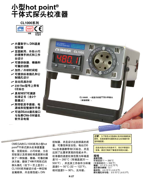
规格温度范围:环境温度11 ~ 260°C(环境温度20 ~ 500°F )精度:±1.5°C (±2.75°F)显示屏分辨率:0.1°稳定性:±0.15°C (±0.3°F) 探头插孔均匀性:±0.15°C (±0.3°F)小型hot point ®干体式探头校准器U 内置数字1⁄32 DIN 温度控制器U 坚固耐用、外形小巧的便携手持式和工作台设计U 可提供快捷、精确和可靠的读数U 加热/冷却时间短U 可提供标准插孔和公制插孔设计U 自动风扇冷却U 230 Vac 型号上带有CE 标志 U 具有NIST 可溯源 校准证书(含2个 数据点)U 附带软质手提箱、电源线和完整操作手册U 可选RS232通讯接口与免费CN9-SW 通讯软件及电缆CL1000A ,一起显示的是TTSS-HH 探头(单独销售)。
注意:为了防范火灾隐患以及对校准器造成损坏,在放回储存位置前务必让校准器冷却至环境温度。
CL1000系列Vac 型号标配OMEGA 的CL1000系列小型hot point ®干体式探头校准器重量轻、坚固结实、小巧玲珑,为在实验室以及现场校准温度探头提供了一种快捷、精确、可靠的解决方案。
提供了4种不同形式的探头插孔(在下一页上显示)。
CL1000系列被设计成一种定制金属箱体,内含高性能1⁄32 DIN控制器,并且设计达到很高的质量、可靠性和安全性。
每台230Vac 校准器都带有CE 标志,并且达到了比要求更高的性能水平。
校准器的温度校准范围为环境温度10 ~ 260°C (环境温度20 ~ 500°F ),并且其工作条件为环境温度0 ~ 50°C (32 ~ 122°F)、 相对湿度0 ~ 90%,无冷凝。
TBS1000 用户手册介绍

TBS1000 系列 数字存储示波器
ZZZ
用户手册
*P077076700*
077-0767-00
xx
TBS1000 系列
数字存储示波器
ZZZ
用户手册
077-0767-00
Copyright © Tektronix. 保留所有权利。许可软件产品由 Tektronix、其子公司或提供商所有,受国 家版权法及国际条约规定的保护。
本保证声明不适用于由于使用不当或者维护保养不当或不足所造成的任何缺陷、故障或损坏。 Tektronix 在本保证声明下没有义务提供以下服务:a) 修理由非 Tektronix 服务代表人员对产品进行安装、修理 或维护所导致的损坏;b) 修理由于使用不当或与不兼容的设备连接造成的损坏;c) 修理由于使用非 Tektronix 提供的电源而造成的任何损坏或故障;d) 维修已改动或者与其他产品集成的产品(如果这 种改动或集成会增加产品维修的时间或难度)。
本保证由 TEKTRONIX 关于本产品而订立,用于替代任何其他的明示或暗示的保证。 TEKTRONIX 及其供 应商拒绝对用于特殊目的的适销性或适用性做任何暗示的保证。 对于违反本保证的情况,TEKTRONIX 负责修理或更换有缺陷产品是提供给客户的唯一和独有的补救措施。 无论 TEKTRONIX 及其供应商是否 被预先告知可能发生任何间接、特殊、意外或引发的损坏,TEKTRONIX 及其供应商对这些损坏都不负有 责任。
[W19 – 03AUG12]
TPP0101 和 TPP0201 探头
保修
Tektronix 保证本产品自发货之日起一年内,不会出现材料和工艺方面的缺陷。如果在保修期内证实任 何此类产品有缺陷,Tektronix 将自主决定,是修复有缺陷的产品(但不收取部件和人工费用)还是提 供替换件以换回有缺陷的产品。Tektronix 在保修工作中使用的部件、模块和替代产品可能是新的,也 可能是具同等性能的翻新件。所有更换的部件、模块和产品均归 Tektronix 所有。
哈希水处理仪表说明

NO3D sc 硝酸盐传感器
用户手册 2008 年 12 月,第 1A 版
美国哈希公司,2007-2008。版权所有。德国印刷。
目录
第一章 技术参数................................................................................................................................................5 1.1 尺寸..................................................................................................................................................................6
第四章 操作运行..............................................................................................................................................19 4.1 使用 sc 控制器...........................................................................................................................................19 4.2 传感器的设置.............................................................................................................................................19 4.3 传感器的数据记录....................................................................................................................................19 4.4 传感器的诊断菜单....................................................................................................................................19 4.5 传感器的设置菜单....................................................................................................................................20 4.6 校准................................................................................................................................................................22 4.6.1 传感器代码校准...................................................................................................................................22 4.6.2 矩阵修正概述........................................................................................................................................23 4.6.3 矩阵修正.................................................................................................................................................24 4.6.3.1 MATX 1 修正(单点矩阵修正)...................................................................................................24 4.6.3.2 MATX 1 CL-修正..................................................................................................................................24 4.6.3.3 MATX 2 修正(两点矩阵修正)...................................................................................................25 4.6.3.4 MATX 2 CL-修正.................................................................................................................................26 4.6.3.5 数值修正................................................................................................................................................27
GODEX EZ-1100 EZ-1200 EZ-1300 说明书
P/N. 920-011321-04Edition 1OCT.11EZ-1100/EZ-1200/EZ-1300 操作手冊FCC COMPLIANCE STATEMENTFOR AMERICAN USERSThis equipment has been tested and found to comply with the limits for a CLASS A digital device, pursuant to Part 15 of the FCC Rules. These limits are designed to provide reasonable protection against harmful interference when the equipment is operated in a commercial environment. This equipment generates, uses, and can radiate radio frequency energy and, if not installed and used in accordance with the instructions, may cause harmful interference to radio communications. Operation of this equipment in a residential area is likely to cause harmful interference in which case the user will be required to correct the interference at his own expense.EMS AND EMI COMPLIANCE STATEMENTFOR EUROPEAN USERSThis equipment has been tested and passed with the requirements relating to electromagnetic compatibility based on the standards EN50081-1 (EN55022 CLASS A) and EN61000-4-2/-3/-4/-5/-6/-8/-11 (IEC Teil 2,3,4). The equipment also tested and passed in accordance with the European Standard EN55022 for the both Radiated and Conducted emissions limits.EZ-1000 SerialTO WHICH THIS DECLARATION RELATESIS IN CONFORMITY WITH THE FOLLOWING STANDARDSEN55022 : 1998,CLSPR 22 , Class A / EN55024 : 1998 IEC 61000-4 Serial / EN61000-3-2 : 2000 / EN 61000-3-3 : 1995 / CRF 47, Part 15/CISPR 22 3rd Edition : 1997,Class A / ANSI C63.4 : 2001 / CNS 13438,CISPR22(Class A) / IEC60950 3rd Edition (1999) / GB4943 : 2001 / GB9254 : 1998 / GB17625.1 : 2003CAUTIONDanger of explosion if battery is incorrectly replacedReplace only with the equivalent type recommended by the manufacturer.Dispose of used batteries according to the manufacturer’s instructions.Specifications are subject to change without notice.警告使用者:這是甲類的資訊產品,在居住的環境中使用時,可能會造成射頻干擾,在這種情況下,使用者會被要求採取某些適當的對策.第1章條碼機 (3)1-1. 簡介 (3)1-2. 系列機種 (3)1-3. 全機器材 (3)1-4. 規格說明 (4)1-5. 通訊埠規格 (5)1-6. 條碼機標準配備零件圖示 (6)第2章條碼機標準配備安裝說明 (7)2-1. 碳帶安裝 (7)2-2. 標籤紙安裝 (8)2-3. 紙捲軸心安裝說明 (9)2-4. 吊牌安裝說明 (10)2-5. USB 驅動程式安裝方式 (10)2-6. 移除 USB 驅動程式 (11)2-7. 電腦連結 (12)第3章條碼機選購裝備安裝說明 (13)3-1. 自動剝紙器零件圖示說明 (13)3-2. 自動剝紙器安裝方式 (13)3-3. 剝紙器安裝圖示說明 (15)3-4. 裁刀零件圖示說明 (16)3-5.裁刀安裝方式 (16)3-6. 記憶卡零件圖示說明 (19)3-7. 記憶卡安裝方式 (19)第4章.LED訊息說明 (21)4-1. LED 訊息說明 (21)4-2. 一般操作 (21)4-3. 自我測試 (22)4-4. 傾印模式 (22)4-5. 標籤紙自動偵測模式 (23)4-6. 熱感/熱轉切換模式 (23)4-7. 操作錯誤訊息 (24)第5章保養維謢與調校 (25)5-1. 印表頭保養與清潔 (25)5-2. 印表頭平衡調校 (25)5-3. 列印線調整 (26)5-4. 裁刀卡紙排除 (26)5-5. 故障排除 (27)第 1 章條碼機1-1. 簡介EZ-1000 系列為商業型條碼機,具人性化設計,不須訓練即可操作;可視需求擴充功能,使工作更為流暢。
2011年LHE1000多点测斜仪器操作手册解析

•
•
• 图2-2探管连接图(外径27mm)
•
1 Φ27mm工具面接头 2 探管 3
充电电池筒
技术参数
• 机芯局部特性 • 内置固态传感器组件,高抗振性能 • 高准确度,高牢靠性,超低功耗 • 专用数据处理软件,消退人工读数误差 • 输出结果可永久保存 • 最多可储存2023组数据 • 电量缺乏时告警 •
探管参数
•
井斜
•
方位
•
磁性工具面角
•
高边工具面角
•
温度测量
•
工作温度范围
•
通信接口
•
电源
•
重量
•
外形尺寸
0~180° ±0.2°
0~360° ±1.0°
0~360°
±0.5°
0~360°
±0.5°
0~125℃ ±2.0℃
0~125℃〔加隔热套 0~260℃〕
RS-2327.2V充电电池筒Fra bibliotek200g
ø27×260mm
理数据时,要在校验磁偏角处选定,以后每次翻开再不需要校验磁偏
角〕点击确定后,就可以看到水平图、垂直图和三维图,点击打印既
可。假设需要打印数据,点击左上角的打印文档既可。
•
4、假设想把刚刚输入的数据保存下来。再次点击保存文件,把
此原文件掩盖就行了。
技术指标
• 初始延时时间: 0~18个小时 • 采集时间间隔: 1秒~18个小时
软件操作见实物和软件操作
LHE1000电子多点测斜仪
多点仪器一般是井队在完钻起钻时使用,通过软 件选点,计算后,可以生动的反映出井身轨迹。 在多点测斜时,确定要将时间在记录表上记录清 晰。 时间记录表是多点选点的依据,格式如下:
- 1、下载文档前请自行甄别文档内容的完整性,平台不提供额外的编辑、内容补充、找答案等附加服务。
- 2、"仅部分预览"的文档,不可在线预览部分如存在完整性等问题,可反馈申请退款(可完整预览的文档不适用该条件!)。
- 3、如文档侵犯您的权益,请联系客服反馈,我们会尽快为您处理(人工客服工作时间:9:00-18:30)。
哈希ez1000硅表说明书
一、概述:
哈希ez1000硅表,是一款具有自动完成化学反应、光电检测、图文显示、变送输出及数据存储等功能的,高精度的在线式自动化仪表;该仪器采用独特的空气搅拌及光电检测技术,使其具有化学反应速度快和测量精度高等卓越特性;该仪器采用了彩色液晶显示器,以丰富的色彩、文字、图表和曲线等方式,显示测量结果、系统信息以及全中文菜单操作界面;人性化的设计理念与高新技术的充分结合,突出体现了该仪器的优越性和产品竞争性。
二、特点:
1、检测下限低,非常适合电厂给水、饱和蒸汽及过热蒸汽的硅含量检测与控制;
2、真正使用单色冷光源的在线式硅表,光源使用寿命长;
3、仪器具有历史曲线记录功能,可存储30天的数据;
4、仪器具有自动标定功能,周期任意设定(此功能需在订货时说明);
5、支持多路水样的测量(可选1—6路);
6、该仪器除添加试剂、标样外,无任何工作量,真正达到了免维护。
三、技术参数
1、测量范围:0~200ug/l、0~2000ug/l 可选
2、精度:±1%F.S
3、重现性:±1%F.S
4、稳定性:漂移≤±1% F.S / 24小时
5、响应时间:最初响应12分钟
6、采样周期:10分钟左右 / 通道
7、水样条件:流量:100 ml / min。
温度:10~45℃。
压力:10 kPa ~ 100 kPa
8、环境条件:温度:5~45℃。
湿度:<85% RH
9、试剂消耗:三种试剂每种约3升/月
10、电流输出:0~20mA﹝此范围内任意设置,多通道仪表各通道独立输出﹞
11、报警输出:继电器常开接点(220V/1A)
12、电源:AC220V±10% 50HZ
13、功耗:≈50VA
14、外型尺寸:720mm(高)×460mm(宽)×300mm(深)
15、开孔尺寸:665mm×405mm
四、仪器结构和工作原理
1、化学原理
在一定酸度条件下,硅酸根与钼酸盐反应生成硅钼黄,再用还原剂还原成硅钼蓝,然后采用分光光度法测定。
磷酸盐在此条件下也发生类似的反应,会对测量产生干扰,通过加入草酸掩蔽磷酸根离子的干扰。
上述显色产物的最大吸收在810nm左右,本仪器选用810nm特制冷光源进行测定。
2、分析流路
测量过程采用定量进样,显色反应,比色分析的方式。
3、电气原理
仪器的电气系统主要由两部分组成。
检测驱动部分:驱动仪表测量系统各执行部件(电磁阀、空气泵)和光源;并对检测器中光电池的电压信号进行数字化处理,实现了仪器的自动化动作和电→光→电的信号转换,以及电信号的数字化过程。
这部分由检测器、A/D单片机电路板、电磁阀和空气泵组成。
五、仪器安装
安装要求和注意事项:
① 分析仪器安装位置尽可能靠近采样点,所取水样应具有代表性;
② 被测水样和环境温度应在5~45℃之间,否则将影响化学分析过程,从而影响测量准确度;
③ 保证水样无杂质和污物,由于检修等原因造成水质不合格时,应断
开水样,仪器停止运行;
④ 安装仪器的工作环境周围,不应有强电磁场和强振动源;
⑤ 仪器要安装在干燥无尘,无腐蚀性气体的环境中;。