最新欠速打滑开关说明资料
F5021说明手册(新版)

第三章
参数介绍 ...................................................................................................................... 33
3.1 参数表 ...............................................................................................................................................................33 3.2 参数设置说明: ...............................................................................................................................................36
1.书脊 2.每章首页只放题目 3.每章加黑色块 4.线路板调深(黑白效果好)
目
第一章 第二章
录
功能介绍 ........................................................................................................................ 3
397第一章功能介绍11功能列表编号备注编号名称备注标准功能st提前开门操作配置sm11a板群控运行10重复开门10上班高峰服务11换站停靠11下班高峰服务12错误指令取消12分散待梯13反向时自动消指令13小区监控14直接停靠14远程监控15满载直驶15轿厢到站钟16待梯时轿内照明风扇自动断电16厅外到站预报灯17自动返基站17厅外到站钟18液晶显示界面操作器18轿厢ic卡楼层服务控制19模拟量速度给定19厅外ic卡呼梯服务控制20数字量速度给定20前后门独立控制21故障历史记录21强迫关门22井道层楼数据自学习22vip贵宾层服务23服务层的任意设置23密码层控制功能24层楼显示字符设置24开关控制单梯服务层切换25司机操作25开关控制群控梯服务层切换26独立运行26开关控制操纵厢按钮非服务层设置27点阵式层楼显示器27停电应急平层28滚动显示运行方向28大楼后备电源运行29自动修正层楼位置信号29地震操作30锁梯服务30语音抱站功能31门区外不能开门的保护3132门光幕保护3233超载保护3334轻载防捣乱3435逆向运行保护3536防打滑保护3637防溜车保护37pdf文件使用试用版本创建www
限位开关说明书(堵煤开关)

工作参数:*储仓温度:-20℃~+60℃(0~140 oF)*最大工作压力:10Bar(150psi)*最小物料介电常数Σr:2.5*壳体工作温度: -20℃~+60℃*储存温度: -20℃~+85℃探头: *FTC131Z:杆式探头,Φ18mm,最长4m杆式探头最大侧向负载为30Nm壳体型号: *铝壳IP55*铝壳IP66*聚酯壳:IP66电缆塞: *IP55壳体:镍铜质标准Pg, NBR密封件,适用线径为7~10mm.*IP66壳体:聚酰胺材质防水型Pg, N—CR密封件,适用线径为5~12mm.电子插件: *端子连线最大截面为1.5mm2*测量频率:短于4m的探头约为750KHZ,对于长度超过4m的探头,切换至450KHZ.*初始容抗(可调):约400PF*开关延迟量:约0.5秒*高低位报警模式选择开关:旋式开关*开关状态指示.红色LED灯双线制交流*电源U~:21V….250V, 50/60HZ供电电子*瞬时外接负载(最长40ms):最大工作电流1.5A; 250V时最大功耗375V A;24V时, 插件EC20Z 最大功耗36V A.*最大压降:11V*连续外接负载:最大工作电流350Ma; 250V时最大功耗87V A;24V时最大功耗8.4V A*250V时最小负载电流:10Ma(2.5V A)*24V时最小负载电流:20mA(0.5V A)*空载电流(有效值):<5mA三线制直流*电源U~:10V (55V)供电电子*允许波纹电压UPP:5V插件EC22Z *最大电流消耗:15mA及EC23Z *负载连接:集电极开路; PNP(EC22Z)或NPN(EC23Z)*最大开关电压:55V*连续外接负载:最大工作电流350MA*最大峰值冲击电流::1.2A,最长20US*最大负载并联容抗:500NF*抗短路及过载保护:响应阀值约550MA*晶体管开路状态下空载电流:<100UA*具有抗反极性保护功能继电输出型*电源U~:20V~125V交/直流供电或U~:21V~250V,50/60HZ电子插件*最大电流消耗(均方根值):5MAEC24Z *最大峰值冲击电流:200MA,最长5MS*脉冲频率:约1.5S*输出:无源翻转触点器*触点器负载能力:U~最大为250V,I~最大为4AP~最大为1000V A(COSφ=1)或P~最大为350V A,COSφ>=0.7U~最大为100V,I~最大为100W*工作寿命:最大接触负载下,至少可工作十万次*外加翻转延迟:最大1.5S测量系统整个系统是由下列部分组成:1NIVOCOMPACT FTI2电源3用户后接控制系统,开关,信号变送器(如过程控制系统,PLC,继电器,微型触点器,灯,喇叭等).工作原理探头于储仓的侧壁作为两个相对的电极组成一个电容器,而此电容器则被施以一个高频电场.基於放电回路的工作原理而获得具体物位值:当探头位于介电数εR为1的大气中时,放电时间常数τ=R.CA,其中R为电路的阻抗.而CA为探头与器壁所组成电容器的容抗.若具有较高介电常数的物料进入电场区域,则容抗值CA增大,时间常数τ亦随之增大.上述时间长数的变化量被读出,NIVOCOMPACT根据一定的开关工作模式被触发只要物料在探头与仓壁或仓顶之间不行成导通桥路,NIVOCOMPACT就具有很强的抗物料积垢能力.内置的最低/最高位报警模式选择功能保证NIVOCOMPACT所具有很高的操作安全性要求的应用场合以静态电流方式工作.高位报警模式:探头被浸没或电源出现故障时,电路断开.低位报警模式:当探头与被测物料脱离或电源出现故障时,电路断开.位于电子插件上的红色LED显示灯开关状态.应用范围FTC131Z主要用来对小型储仓中细粒散料进行限位探测.FTC331Z用来对大型储仓中细粒或粗粒散料进行限位探测.若储仓中盛放很大颗粒或磨损性很强的物料,NIVOCOMPACTFTC331Z只能用来实现高限位探测.探头之间距离为避免探头之间的相互干扰,不同探头之间应保证至少0.5M的间距位于相邻的由非导电材料组成的储仓中的探头之间亦应保证起码0.5M的距离利用气动式加料机对储仓加料时,探头之间距应更大一些,这样,即使探头晃动,亦能保证其相互间最小间距之要求.储仓加料加料物流应避免直接指向探头.室外安装作为附件供用户选用的全天候保护罩对铝壳结构的Nivocompact开关起到防过热及冷凝之作用.一般而言,大幅度的温度变化极易引起冷凝现象.电气连线(接线)各种不同电子插件的主要特性: 位于产品标牌上的定购代码中的最后一位数字代表位于Nivocompact FTC开关中电子插件的型号:1=电子插件EC20Z双线制交流供电21V (250V)电子开关,最大电流350mA2=电子插件EC22Z三线制直流供电10V (55V)晶体管电路,负载连接PNP,最大电流350mA3=电子插件EC23Z三线制直流供电10V (55V)晶体管电路,负载连接NPN,最大电流350mA4=电子插件EC24Z无源继电输出交流供电21V...250V或直流供电20V (125V)负载极限: 注意与Nivocompact所连负载的极限值超出负载极限会损害或彻底损坏电子插件线径: 工作电流很小,故只需要小线径的电缆建议使用线截面为0.5~1.5mm2的普通电缆接地,与大地等势:必须保证Nivocompact的良好接地性,使其工作可靠,免受外界干扰可将Nivocompact与接地的金属或钢筋型罐壁相连,或将它与大地等势体PE 相连.若在塑料质储仓中已设反极板,则必须在Nivocompact与此反极板之间用一根短线进行接地连接.建立一个等势面势(与大地等势,接地)须严格遵循所有防爆规定.当电子插件安装与Nivocompact中时,自动满足设计认可证书中(A7)1及2所有专门要求/指标.双线制交流供电电子插件EC20Z的连线: 正象所有开关一样,带电子插件EC20Z的物位开关Nivocompact必须与负载(如继电器,微触点器,灯泡等)串接与电源上.在没有任何中介负载情形下,将开关与电源直接相连(短路)会引起迅速而永久的电子插件损坏.负载可串接与电子插件端子1或2的认一端L1亦可与端子1或2的任一端相连.电源电压: 电子插件接线端子1与2之间的端电压值不得低于21V ,电源的端压要稍高于21V,以不偿负载引起的压降.负载开路: 值得注意的是,位报警状态下, Nivocompact的电子插件中的电子开关断路,但此时与之串接的负载并未真正与电源脱开.由于电子插件本身的工作电流要求,此时一个很小的”空载电流”依然流过负载.若负载正好是一只保持电流很小的继电器时,继电器有可能拒绝释放,此时应在继电器两端并接一个负载,如电位器,信号灯等.保险丝: 确保保险丝的功率因子与最大外接负载相匹配.此细径保险丝对电子插件EC20Z不起保护作用三线制直流供电的电子插件EC22Z(PNP)的连线负载受控与晶体管: 接与端子3的负载受控与一只晶体管,类属非接触控制,不会发生返跳现象.正常开关状态下,端子3电位为正物位报警或电源发生故障时,晶体管开路.抗短路保护: 位与端子1与3之间的负载电路具有抗过载及短路能力(脉冲过载保护).过载或短路时,晶体管开路.抗峰压保护: 与强感应仪表相连时,必须接入一只限压器.三线制直流供电的电子插件EC23Z(NPN)的连接负载受控子晶体管电路: 接与端子3的负载受控与一只晶体管,类属非接触控制,故不会发生返跳现象.正常开关状态下,端子3电位为负.物位报警或电源发生故障时,晶体管开路.抗短路保护: 位与端子2和3之间的负载电路具有抗过载及短路的能力(脉冲过载保护) 过载或短路情形下,晶体管开路.抗峰压保护; 与强感应仪表相连时,应接入一只限压器.交/直流供电的电子插件EC24Z的连线电源: 交流供电,L1或N任一端皆可与端子1相连直流供电,L+或L-任一端皆可与端子1相连.服务于负载的继电触点器: 通过一只无源继电触点器(翻转触点器)实现负载的连接,物位报警或电源发生故障时,继电触点器触发,使端子3与4之间短路.抗峰压及短路保护: 在强感应仪表上接入一只火花压制器,用来保护继电触点器.发生短路现象时,细径保险丝F2(功率因子取决于负载大小)可对继电触点器起到保护作用.标定工具准备*齿宽3MM的螺丝刀*齿宽5MM的螺丝刀旋式开关及其他标定过程中所涉调节元件均位于壳体中电子插件上.紧挨标定元件的是电源输入端子,其上电压最大可达250V只允许使用除齿部之外全绝缘的螺丝刀,否则在进行标定之前,必须在电源输入端子上贴上绝缘胶带.容抗标定进行容抗标定时,储仓必须空仓或物位低於探头起码200MM●接通电源●按图23至25的次序进行标定●标定过程中避免水气进入壳体当探头表面被非导电,低介电常数的=固体散料覆盖时,只有当纵向安装探头的一段或横向安装的全部被物料浸没时,NIVOCOMPACT开关才会被触发探头的被覆盖程度取决于於标定工程.反向旋转微标元件,可使NIVOCOMPACT的反应稍许迟钝一些.限位报警模式利用旋式开关,用户可根据实际需要选择合适的限位报警模式*高位报警模式: 探头被物料浸没或电源发生故障时,电流回路开路*低位报警模式:探头裸露於大气中或电源发生故障时,电源回路开路. 功能测试探头裸露於大气中时,用一只带有绝缘柄的螺丝刀接触电子插件的中央紧固螺母,模拟固体散料浸没探头的情形.此时,LED灯的显示状态翻转上述过程仅可用来对仪表的功能控制性能进行测试只有通过现场加料或空仓作业才能真正检查仪表的限位探测功能是否正常.试验过程中物位应:_与侧向安装杆式探头的安装点等高_与纵向安装杆式探头杆端点位置等高_与缆式探头的重锤位置等高!故障排除出现故障时,首先应检查确认*NIVOCOMPACT连接正常*与储仓或反极板接地良好*电源供电正常*所有相连仪表工作正常*使用EC20Z插件时,对相连仪表的最小负载;量要求得到满足*限位报警模式选择正确*标定正确.。
Eaton EverTough 高性能押滑器说明书

®deEverT ough de Eaton: Ahoraincluso más fuerteEaton ha hecho los embragues EverT ough inclusomás fuertes . Todas las versiones de ajuste automático y ajuste manual tienen las siguientes características nuevas:Tres engrasadores zerk• Acceso más fácil para el mantenimiento.Placas de impulso más amplias• Proporciona un área de contacto incrementada: esto permite que el embrague se use con los dedos más amplios de los sistemas de desembrague hidráulico.• Ayuda a reducir las fallas debido a un ajuste incorrecto.RESPALDADO POR ELSOPORTE DET res engrasadores zerkEverT ough Self-Adjust:• L a exclusiva tecnología deajuste automático de Eatonmantiene el embrague enconstante ajuste manteniendo la posición de liberación del cojinete.• I ncluye un indicador de desgaste fácil de observar.• E limina 13 ajustes manualespara cada camión, en promedio.Ajuste manual EverT ough:• L os embragues de AjusteManual EverT ough presentan tecnología Kwik-Adjustprobada para realizar ajustes de embragues más rápidos y simples.• E l anillo de ajuste PowerThread de Eaton elimina el uso de la fuerza y permite que el ajuste sea más fácil.• E l ajuste requiereaproximadamente la mitad del movimiento de los anillos de ajuste estándar.Cartera de EverT ough:ough piezas correctas con piezas originales al mismo tiempo.EatonGrupo Vehicular13100 E. Michigan Ave.Galesburg, MI 49053 USA 800-826-HELP (4357)/roadranger © 2019 EatonTodos los derechos reservados. Impreso en Estados Unidos.CLSL1514SP 0719Para obtener especificaciones o contactarse con el servicio de asistencia, llame al1-800-826-HELP (4357) o visite /roadranger. En México llame al 001-800-826-4357.Roadranger: Eaton y sus asociados deconfianza le proveen los mejores productos y servicios de la industria, asegurándole más tiempo en las carreteras.RESPALDADO POR ELSOPORTE DENota: Las características y especificaciones mencionadas en este documento están sujetas a cambios sin previo aviso yrepresentan las capacidades máximas del software y los productos con todas lasopciones instaladas. Si bien se ha hecho todo lo posible por garantizar la exactitud de la información incluida aquí, Eaton no hace ninguna declaración acerca de lo completa, correcta y exacta que esta pueda ser y no asume ninguna responsabilidad en caso de errores u omisiones. Las características y la funcionalidad pueden variar dependiendo de las opciones seleccionadas.Eaton, Fuller, Roadranger, Solo, UltraShift y Fuller Advantage son marcas registradas de Eaton. Todas las marcas comerciales, logotipos y derechos de autor pertenecen a sus respectivos propietarios.Embragues de alto rendimiento EverT ough de EatonUna amplia cartera de productos le ayuda a evitar el costoso error de sobreespecificar su embrague.EverTough • E specificación del mercado de repuestos • Garantía de kilometraje de dos años/ilimitado • I ntervalo de lubricación de 40 233 kilómetros [25 000 millas]Pesos de envío estimados: 15,5" = 150 lb, 14" = 110 lbTodos los embragues EverTough están diseñados específicamente para clientes del mercado de repuestos para lograr el equilibrio necesario entre precio y rendimiento:• Revestimientos de cerámica.• D isponible en diseños de7, 8, 9 y 10 resortes.• C lasificaciones de torsiónde 1400 hasta 2050 lb.ft.• T res engrasadores zerken el cojinete de liberación.• I ntervalo de lubricaciónde 40 233 kilómetros [25 000 millas].• A mortiguador de primeracalidad de Eaton que reduce las vibraciones torsionales del tren motriz y satisface las expectativas de larga vida de los fabricantes del equipo original (OEM) del vehículo.• L os pines separadorespositivos garantizan unaseparación igual de las placas, un engranaje sin problemas y un funcionamiento más frío.• U n deflector de contaminacióntotalmente redondeado queprotege de residuos.• E l resorte de levas de aceroinoxidable ofrece mayor durabilidad y una vida útil prolongada.• N o se requiere capacitacióntécnica adicional. Procesos deinstalación similares entre los modelos de ajuste automático y manual.• T odos los embraguesEverTough vienen con una garantía de kilometrajeilimitado de dos años y están respaldados por el soporte Roadranger ®.。
TFX1U型防滑器说明书

意 义
88
系统各部件正常。
88.
系统各部件正常,但某些部件曾经发生过故障,现已恢复正常,其故障代码将在“81”代码后面显示。
1.0.
第一轴防滑排风阀的充风电磁铁故障,
1.1.
第一轴防滑排风阀的排风电磁铁故障。
2.0.
第二轴防滑排风阀的充风电磁铁故障,
2.1.
第二轴防滑排风阀的排风电磁铁故障。
6.5当出现“..”故障信息时,表示全部速度部件或全部防滑排风阀或两者均出现固定性故障,该台防滑器已全部失去防滑保护作用,应切除防滑器直流48V供电,并及时进行系统检查和维修,正常后重新投入运行。
6.6当出现本说明书未说明的显示信息时,也按照6.5项所述的方法处理。
2.5“诊断”功能执行过程中,若车辆运行速度高于3km/h时,诊断操作将自动停止,并转入防滑程序的运行。
表1TFX1U型防滑器功能代码信息表
显示功能代码
意义
88
系统各部件正常
89
按钮开关已按下,其功能已开始执行。
87
CPU自检。
86
RAM自检。
85
ROM自检。
84
车门控制信号接通。
83
各速度传感器检查。
6.3当出现某轴传感器固定性故障代码时,由于TFX1U型防滑器具有邻位互补功能,因此,只要相应轴的防滑排风阀无故障,该轴防滑保护作用将与相邻轴相同。其防滑保护功能得到部分补偿。但在停车状态下应及时修复,然后清除故障代码并通过系统自诊断进行确认。
6.4当出现某轴防滑排风阀固定性故障代码时,该轴的防滑保护功能将失效。在停车状态下应及时修理或更换,然后清除故障代码并通过系统自诊断进行确认。
1.电源通断功能
欠速测速装置说明书

用户手册60-23P欠速测速装置(符合94/9CE “A TEX”易爆的2区和22区)1、概述欠速测速装置是对于轴转速或其他旋转装置速度监测的装置。
用于检测皮带欠速报警,一般安装在从动滚筒轴端。
皮带欠速后,触动报警开关,输送机就会保护性停机。
正常后自动恢复。
启动时有10-12秒延时,来保证设备起动过程。
2、产品使用环境2.1周围环境温度:-20~+65℃2.2周围环境湿度:无要求2.3可应用在易爆的2区和22区(符合94/9CE “ATEX”)3、主要技术参数3.1电源:AC220/110V ±10%,报警开关:NO/NC3.2报警触电容量:120V AC 2A,无感应负载。
3.3外壳:尼龙密闭防风雨外壳,IP65。
3.4外形尺寸:φ115,长1603.5感应距离(铁类元件):10mm3.6最高响应频率:62HZ,可特殊要求。
3.7报警点设定范围:60-600脉冲/分,可特殊要求。
3.8精度:±5%设定点数值3.9重量:1.3K g4、工作原理欠速测速装置前部的电路能探测10毫米近的铁类元件,安装在旋转轴或滚筒的铁类元件按一定的频率通过开关前端时开关就能探测到旋转装置的转速。
当铁类元件通过开关频率降低到设定植以下时,开关输出报警开关的信号。
此信号可通过电路控制停机。
速度正常后开关自动复位。
5、安装5.1打开包装之前,应检查外包装是否有挤压、破损。
安装尺寸:开关中心距安装孔68,(孔)2-φ115.3装之前应仔细阅读本册用于检测皮带速度的开关通常安装在输送机尾部滚筒或其他从动滚筒。
安装时,铁类突出件建议不小于直径35,应距开关前部10毫米以内,但不能发生碰撞。
开关通常用支架通过两个M10螺栓固定。
一定加弹簧防松垫片。
5.4打开有文字标记的前盖,确定电源220AC/110VAC 及相应接线端子。
报警开关有常开和常闭,根据需要选择。
如用在防爆环境,一定要另配专用电缆接头,螺纹PG13.5。
FDR-2说明书(新板)

图1:用户分界开关控制器外形图
说明:CTA为A相CT;CTC为C相CT;CTZ为零序CT;
TA航空插头接线图;FXQ为分闸线圈;HXQ为合闸线圈
.就近遥控操作方法:
键:解锁键;A键:分闸键;D键:合闸键;
遥控操作时,先按B键1秒,3秒内再按功能键;
如:分闸操作时,先按下B键1秒后,3秒内再按A键;
合闸操作时,先按下B键1秒后,3秒内再按D键;
智能掌上机功能描述
搜索设备
选择‘搜索设备’选项,PDA会搜索处于通信范围内(空旷距离小于150米)控制器,如搜索范围内有控制器,选择对应控制器的设备号,进入显示有选中的设备号的主界
面窗口。
查询状态
选择‘查询状态’,显示结果为当前控制器的实时状态值。
.查询记录
选择‘查询记录’,显示过去发生过的最近发生的30条故障记录;。
打滑开关
接线图
BN
BK
BU
棕
黑
兰
安装说明
电气接线图
所有的传动装置,如螺旋输送机、提升机、皮带输送机、拉链机、破碎机等都应在其被传动轴处 (机器尾端)进行安装,见必拘泥于此图,在不影响正 常工作的前提下只要满足“单位时间内给探头间隔均匀的脉冲信号”这个条件即可。 机械安装工序:
订货需知 为了方便您快速、准确的选购所需产品,请在购买前提供具体的设备类型、具体转速、安装结构、
是否选配继电器等参数,我们将为您推荐最合适的产品。 本公司另可提供 DC24V 三线(不用中间继电器直送中控)的产品,采购时请详细说明。
联系人:程经理 电话:13921449225 Q Q:350190284 邮箱:erzhite@126.com 网址:www.jsurt.cn 地址:南京市和燕路508号山泉产业园302幢
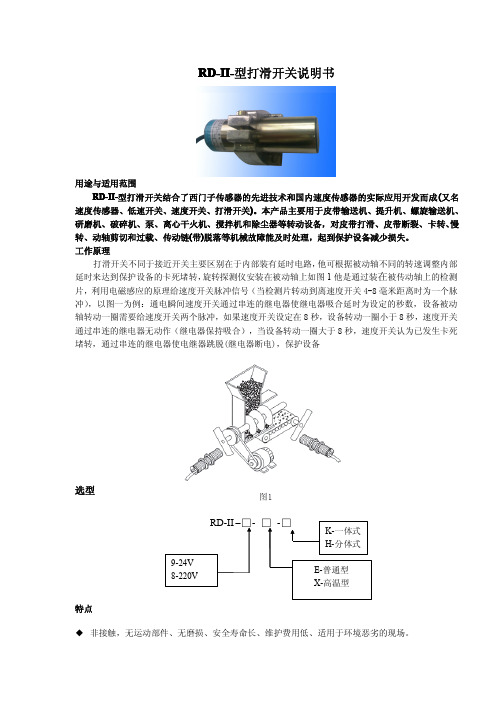
RD-II-型打滑开关说明书
用途与适用范围 RD-II-型打滑开关结合了西门子传感器的先进技术和国内速度传感器的实际应用开发而成 (又名
速度传感器、低速开关、速度开关、打滑开关)。本产品主要用于皮带输送机、提升机、螺旋输送机、 研磨机、破碎机、泵、离心干火机、搅拌机和除尘器等转动设备,对皮带打滑、皮带断裂、卡转、慢 转、动轴剪切和过载、传动链(带)脱落等机械故障能及时处理,起到保护设备减少损失。 工作原理
选型
RD-II –□- □ -□
9-24V 8-220V
K-一体式 H-分体式
E-普通型 X-高温型
特点
◆ 非接触,无运动部件、无磨损、安全寿命长、维护费用低、适用于环境恶劣的现场。
◆ 一体化结构,免设置、调试,安装简单。
◆ 体积小、重量轻、寿命长 ◆ 具有负载短路保护功能——误将旋转探测器直接接电源不会损坏旋转探测器。(不能超过 1 分钟) ◆ 输出信号既可与现场设备联锁使用,也可送达 DCS 控制系统 ◆ 配有状态指示灯。设备正常运行时,指示灯“闪烁”;停机时,指示灯“常亮”。 ◆ 跳脱时间可调 3-18S
ESPB-030 失速开关 速度打滑检测器说明书
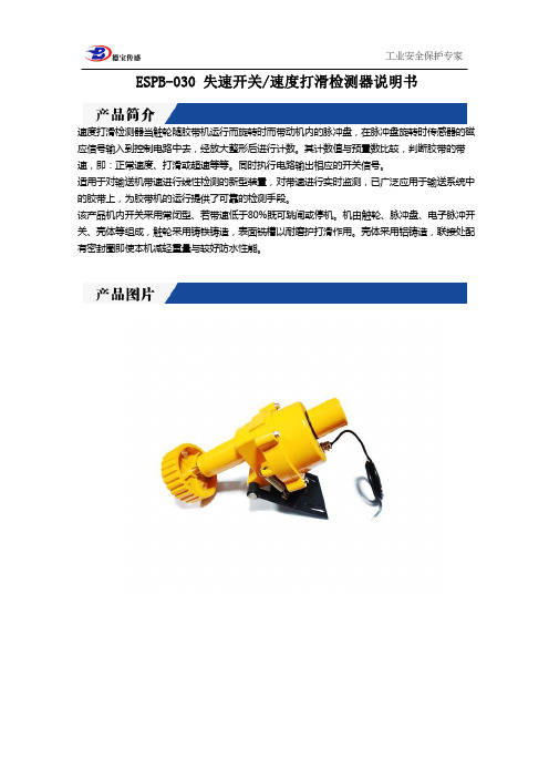
ESPB-030 失速开关/速度打滑检测器说明书
速度打滑检测器当触轮随胶带机运行而旋转时而带动机内的脉冲盘,在脉冲盘旋转时传感器的磁应信号输入到控制电路中去,经放大整形后进行计数。
其计数值与预置数比较,判断胶带的带速,即:正常速度、打滑或超速等等。
同时执行电路输出相应的开关信号。
适用于对输送机带速进行线性检测的新型装置,对带速进行实时监测,已广泛应用于输送系统中的胶带上,为胶带机的运行提供了可靠的检测手段。
该产品机内开关采用常闭型、若带速低于80%既可跳闸或停机。
机由触轮、脉冲盘、电子脉冲开关、壳体等组成,触轮采用铸铁铸造,表面铣槽以耐磨护打滑作用。
壳体采用铝铸造,联接处配有密封圈即使本机减轻重量与较好防水性能。
打滑检测器 皮带失速监控器 说明书

YF-DH-III型打滑检测器是一种费用低、可靠性好、对胶带速度及其它旋转装置简单通用的速度监测装置。
失速开关放置在防风雨的密封、抗腐蚀外壳内,允许暴露在恶劣环境下。
技术参数:
工作电压:220V/AC,±15%触点容量:AC/250V/2A非感负载。
工作温度范围:-40℃-+60℃检测方式:接触光电式
输出触点:2常开、2常闭
检测范围:0.2米/秒-5.0米/秒(拨码开关调节)
防护等级:IP67
通讯:RS-485地址编码终端器(用户选配)
通讯距离:6芯双绞线时1.2公里,光缆时50公里
设备描述:
●一体化接触轮检测,寿命长、运行维护费用低:
●两螺栓固定,确保安装简便;
●一体化结构,集中的扩展装置:
●进口运动部件、低磨损、安全寿命长
●报警/延时(旋转设备起动过程中尚未达到工作速度时,10秒延时报警)。
●速度参数可现场设置(8位拨码开关)
安装与接线图。
打滑开关说明书

KGS-12S型矿用本安型带式输送机速度传感器使用说明书兖州市科欣机电设备制造有限公司目次一、概述…………………………………………………………………………………………二、型号编制、主要技术参数、工作条件……………………………………………………三、技术特性……………………………………………………………………………………四、工作原理……………………………………………………………………………………五、安装、调试…………………………………………………………………………………六、故障分析与排除……………………………………………………………………………七、运输、储存…………………………………………………………………………………八、安全警示录…………………………………………………………………………………九、质量承诺……………………………………………………………………………………十、安装示意图…………………………………………………………………………………一、概述速度传感器是利用光栅旋转片在光电传感器中的转动,产生一系列脉冲信号,通过检测脉冲信号的高低,就可以检测出皮带机运行速度的高低。
还可利用微电脑芯片,输出皮带机运行的数字带速值。
它适用于沼气、瓦斯和煤尘的矿井中,用作胶带低速打滑保护的速度传感器。
它与兖州科欣公司生产的KXJW型微机控制箱配套使用能够很好的实现对胶带低速打滑的保护。
二、型号编制、主要技术参数、工作条件1.型号编制:输送机用额定电压12V(或根据用户需要调整)速度传感器本质安全型矿用2.主要技术参数2.1防爆型式:矿用本安型ExibI2.2工作电压:DC24V2.3工作电流:不大于70mA2.4速度范围:0~4.5m/s2.5传动方式:传感器上的金属传动轮与胶带接触传动2.6重量:6.7㎏2.7关联设备:名称:隔爆兼本安微机控制箱型号:KXJW-127/30-64防爆型式:隔爆兼本安Exd[ib]I防爆合格证号:生产单位:兖州科欣机电公司3.工作条件3.1大气压力:80~110KPa3.2环境温度:0~+40℃3.3相对湿度:≤95%(+25℃)3.4有沼气及煤尘的煤矿井下,周围应无足以腐蚀金属和绝缘的流动性化学物质3.5无剧烈振动和冲击的地方三、技术特性1.本传感器所接控制回路电源应为12V本安电源。
欠速打滑开关说明资料

欠速打滑开关说明资料本页仅作为文档封面,使用时可以删除This document is for reference only-rar21year.March2 欠速打滑开关概述;欠速打滑开关是一种可靠性强、对轴转速及其他旋转装置简单通用的监测装置。
当监测到当前转速信号低于正常转速范围开关输出开关信号,以供报警或停机。
无运动部件、无磨损、安全寿命长,一体化结构,集中的控制装置,设定或故障检修简单。
安装:欠速打滑开关安装在输送机从动轮或其他能等于实际胶带运行速度的转轴侧面,从动轮或转轴侧面需焊接一个可供欠速打滑开关感应面(感应面必须采用铁质材料),感应面截面尺寸不小于50mm ×50mm ,欠速打滑开关与感应面最大距离为25mm 。
感应面为欠速打滑开关提供一个脉冲信号,从动轮旋转一圈感应面通过一次欠速打滑开关区域,从而产生一个脉冲信号。
当产生一次脉冲信号时,欠速打滑开关面板上的脉冲指示灯会闪一次。
需要确保除感应面外,从动轮侧面无任何可使欠速打滑开关产生脉冲信号的金属物体。
设置: 先按 键出现数码闪烁,再按 键到显示:1、2、3。
再按 键出现数码闪烁,再按 键调整打滑转数值,再按 键设置成功。
工作原理:欠速打滑开关是为了检测皮带机尾轮的旋转速度,开关与尾轴无接触。
当尾轴随胶带机运行旋转时而带动感应片,感应片与检测器发生的感应信号输入到控制电路中去。
经放大,整形后进行计数,其计数值与预置数比较,从而判断胶带的速度,既:在达到低于打滑速度时执行电路输出相应的开关信号,使主机停机。
本开关可调整速度值。
技术指标:1、工作电源:AC220V 频率:50-60Hz2、温度范围:-20℃~+70℃3、启动延时:约10秒钟4、检测距离:从检测器到感应块之间最大距离Sn :20mm5、触点容量:240V/AC ,3A ,输出值一组常开,一组常闭6、转 速:30-999转/分SETSET SET SET123456。
ALPS ALPINE SSSF Series滑动开关产品基本信息说明书

|Dimensions |Mounting Hole Dimensions |Actuator Configuration |Shape of Frame Leg |Circuit Diagram |Packing Specifications |Soldering Conditions Slide Switch > SSSF Series > SSSF0215008.5(H)mm, 2.0mm-travel Type SSSF Series||Travel 2mmActuator directions Vertical Actuator length 6mm Poles 2Positions 2Operating force Refer to the dimensions.Mounting methodSnap-in (t1.6)Changeover timing Non shorting SolderingManual, DipOperating temperature range-40℃ to +85℃Part number Series Common Info SSSF021500Rating (max.)/(min.) (Resistive load)0.1A 30V DC/50μA 3V DC Electrical performanceContact resistance(Initial performance/After lifetime)25mΩ max./65mΩ max.Insulation resistance 100MΩ min. 500V DC Voltage proof 500V AC for 1 minute Mechanical performanceTerminal strength5N for 1 minuteActuator strengthOperating direction 30N Pulling direction30NDurabilityOperating life without load10,000 cycles 45mΩ max.Operating life with load (at max. rated load)10,000 cycles 65mΩ max.Environmental performance Cold-40℃ 500h Dry heat85℃ 500hDamp heat60℃, 90 to 95%RH 500hMinimum order unit (pcs.)Japan 800Export 4,000DimensionsMounting Hole DimensionsViewed from direction A in the dimensions. Actuator ConfigurationShape of Frame LegCircuit DiagramPacking Specifications BulkNumber of packages (pcs.)1 case / Japan8001 case / export packing4,000Export package measurements (mm)400×270×290Soldering Conditions Reference for Dip SolderingItems Preheating temperature100℃ max. Preheating time60s max.Dip soldering Soldering temperature260±5℃Duration of immersion10±1sReference for Hand SolderingSoldering temperature350±10℃Soldering time3+1/0sNotes are common to this series/models.1. This site catalog shows only outline specifications. When using the products, pleaseobtain formal specifications for supply.2. Please place purchase orders per minimum order unit (integer).3. Products other than those listed in the above chart are also available. Please contact usfor details.Inquiries about ProductsInquiryCOPYRIGHT© 2020 ALPS ALPINE CO., LTD。
JWS国际认证滑槽型开关说明书

JWS21RAA JWS11BAA JWS11RAACSeries JWSInternationally Approved RockersB50I n d i c a t o r sA c c e s s o r i e sS u p p l e m e n t T a c t i l e sK e y l o c k s R o t a r i e s P u s h b u t t o n s I l l u m i n a t e d P BS l i d e sP r o g r a m m a b l eT o u c hT i l tT o g g l e sGeneral SpecificationsElectrical Capacity (Resistive Load)Power Level:10A @ 125/250V AC6A @ 125/250V AC (UL/CSA)5A (3A) @ 125/250V AC (VDE)Other RatingsContact Resistance: 10 milliohms maximum Insulation Resistance: 500 megohms minimum @ 500V DC Dielectric Strength: 2,000V AC minimum between contacts for 1 minute minimum; 4,000V AC minimum between contacts & case for 1 minute minimum Mechanical Life: 30,000 operations minimum Electrical Life: 10,000 operations minimum Nominal Operating Force: Single Pole 3.92N & Double Pole 5.39N Angle of Throw: 30°Materials & FinishesRocker: Polyphenylene ether (UL94V-0)Housing/Case: Polyamide (UL94V-0)Movable Contactor: Copper with silver plating Movable Contacts: Silver Stationary Contacts: SilverEnd Terminals: Brass with silver plating Common Terminals: Copper with silver platingLamp Terminals: Phosphor bronze with tin plating (illuminated models only)Environmental DataOperating Temp Range: –25°C through +70°C (–13°F through +158°F) for nonilluminated models; –25°C through +50°C (–13°F through +122°F) for illuminated models Humidity: 90 ~ 95% humidity for 96 hours @ 40°C (104°F)Vibration: 10 ~ 55Hz with peak-to-peak amplitude of 1.5mm traversing the frequency range & returning in 15 minutes; 3 right angled directions for 2 hoursShock: 50G (490m/s 2) acceleration (tested in 6 right angled directions, with 5 shocks in each direction) Sealing: Dust resistant inner sealInstallationSoldering: Manual Soldering: See Profile A in Supplement section.Cleaning: These devices are not process sealed. Hand cleaning locally using alcohol based solution.Standards & CertificationsFlammability Standards: UL94V-0 for rocker & housing/case UL: File No. E44145All JWS models recognized at 6A @ 125/250V AC CSA: File No. 023535_0_000 All JWS models certified at 6A @ 125/250V AC VDE: License No. 119153All JWS models approved at 5A (3A) @ 125/250V ACSeries JWSInternationally Approved Rockers B51I n d i c a t o r s A c c e s s o r i e s S u p p l e m e n t T a c t i l e s K e y l o c k sR o t a r i e sP u s h b u t t o n sI l l u m i n a t e d P BS l i d e s P r o g r a m m a b l e T o g g l esT o u c hT i lt Distinctive CharacteristicsRocker caps and housing available in a variety of colors.Protective barrier available to prevent accidental actuation.Constructed for dust resistance with interior cover of polyamide between actuator and contact area.Easy, crisp actuation.Small size well suited for telecommunication, measuring, automation, and consumer applications.Terminals are molded in to lock out flux, dust, and other contaminants.Outer case of heat resistant resin meets UL94V-0 flammability standard.Actual SizeSeries JWSInternationally Approved RockersB52I n d i c a t o r sA c c e s s o r i e sS u p p l e m e n t T a c t i l e sK e y l o c k sR o t a r i e sP u s h b u t t o n sI l l u m i n a t e d P B S l i d e sP r o g r a m m a b l eT o u c hT i l t T o g g l e sTYPICAL SWITCH ORDERING EXAMPLEBlack Housing/No BarrierDPSTON-NONE-OFF CircuitDESCRIPTION FOR TYPICAL ORDERING EXAMPLEJWS21RAABlack Rocker Cap * For Nonilluminated onlyIMPORTANT:cULus & VDE markings are standard on all models. Models & specific ratings are noted on General Specifications page.Note: Wire harness & cable assemblies offered only in AmericasSeries JWS Internationally Approved Rockers B53I n d i c a t o r s A c c e s s o r i e sS u p p l e m e n t T a c t i l e s K e y l o c k s R o t a r i e s P u s h b u t t o n s I l l u m i n a t e d P B S l i d e s P r o g r a m m a b l e T o g g l es T o u c h T i l tS Power Level 10A @ 125/250V AC 6A @ 125/250V AC (UL/CSA) 5A (3A) @ 125/250V AC (VDE)RATINGBARRIER TYPES & COLORSRNo-barrier type hasa flat flange whichis an integral partof the switch.Barrier Material: PolyamideFinish: MatteBarrier AT219 is factory assembled.Dimensions for barrier areshown in the Accessories section.No BarrierB With BarrierABlackBarrier Color Available:CAP COLORSCap Material:Polyphenelene OxideFinish: MatteRocker cap is an integral part of the switch and not available separately.* Ivory for nonilluminated models only.Black* Ivory RedBlack Ivory (for nonilluminated models only)Cap ColorsAvailable:A B CABMaterial: PolyamideFinish: Matte Colors Available:HOUSINGTERMINALSSolder Lug/.187” (4.75mm) Quick ConnectSwitch assembly with connectorsis not UL, CSA, C-UL, or VDE approved.Switch Lamp(spot illuminated models only) .026.047Thk = (0.5).020Thk = (0.25).010.118Series JWSInternationally Approved RockersB54I n d i c a t o r sA c c e s s o r i e sS u p p l e m e n tT a c t i l e sK e y l o c k sR o t a r i e sP u s h b u t t o n sI l l u m i n a t e d P B S l i d e sP r o g r a m m a b l eT o u c hT i l tT o g g l e sPANEL CUTOUT & PANEL THICKNESS RANGESTYPICAL SWITCH DIMENSIONSJWS11RCANonilluminated • No BarrierDouble PoleJWS21RAADPST models have IEC symbols for On-Off on the flange.Nonilluminated • No BarrierSingle PolePanel Thickness Ranges:Without Barrier:.030” ~ .079” (0.75mm ~ 2.0mm)With Barrier:.024” ~ .059” (0.6mm ~ 1.5mm)Series JWSInternationally Approved RockersB55I n d i c a t o r s A c c e s s o r i e sS u p p l e m e n tT a c t i l e s K e y l o c k sR o t a r i e sP u s h b u t t o n sI l l u m i n a t e d P BS l i d e s P r o g r a m m a b l e T o g g l esT o u c hT i l tTYPICAL SWITCH DIMENSIONSJWS11BBA-AJWS11RCAFDouble PoleNonilluminated • With BarrierSingle PoleSpot Illuminated • No BarrierDPST models have IEC symbols for On-Off on the flange. JWS21BAA-ASingle PoleNonilluminated • With BarrierSingle PoleSpot Illuminated • With BarrierJWS11BAAF-A.071.071JWS21RAA JWS11BAA JWS11RAAC。
WK32G_A5型号的3-way 2-position直动式滑崖阀门说明书

-Screw-in cartridge valve -For cavity AM-All external parts with zinc-nickel coating according to DIN EN ISO 19598-Installation in threaded port body type GAMA-The slip-on coil can be rotated, and it can be replaced without opening the hydraulic envelope -High pressure wet-armature solenoids-Various plug-connector systems and voltages are available-Optimized Δp values -With manual overrideDirectional valve 3-way/2-positionQ max = 7.5 gpm, p max = 3600 psiswitching solenoid with emergency override, direct acting, spool typeType series: WK32G_A5…DescriptionThe 3-way/2-position solenoid operated spool valves, series WK32…, are size 5, direct acting, pressure ba-lanced screw-in valves with a 3/4-16 UNF-2A mounting thread. They are designed on the proven sliding-spool principle. The straightforward design delivers an out-standing price/performance ratio and excellent pres-sure-drop/flow rate values. All external parts of the screw-in valves are zinc-nickel plated, and are thus sui-table for use in the harshest operating environments. The slip-on coils can be replaced without opening the hydraulic envelope and can be positioned at any angle through 360°. These valves are mainly used in mobile and industrial applications as pilot valves for controlling the travel direction of actuators such as hy-draulic motors and cylinders. For self-assembly, plea-se refer to the section related data sheets.SymbolTechnical DataNOTE!The switching time can be strongly de-pendent on flow rate, pressure, oil viscosity and the dwell time under pressure. In practice, the switching time may th-erefore deviate from the specified value range.Performance graphsmeasured with oil viscosity 33.0 mm²/s (cSt), coil at steady-state temperature and 10 % undervoltage p = f (Q) Performance limitp = f (Q) Performance limit400-PG-02200p [bar (psi)]50 (700)100 (1400)150 (2100)200 (2900)250 (3600)300 (4300)Version "N" - 27/25 WQ [l/min (gpm)]30(7.5) 25(6.5)20(5)15(3.75)10(2.5)5(1.25)400-PG-02210p [bar (psi)]10 (140)20 (285)30 (430)40 (570)50 (700)60 (860)Version "E" - 17 WQ [l/min (gpm)]30(7.5) 25(6.5)20(5)15(3.75)10(2.5)5(1.25)Δp = f (Q) Pressure drop-flow rate characteristic400-PG-022202 (30)4 (60)6 (85)8 (120)10 (140)12 (170)p [bar (psi)]∆2)1)1) 1 → 22) 2 → 3Q [l/min (gpm)]30(7.5) 25(6.5)20(5)15(3.75)10(2.5)5(1.25)Dimensions and sectional viewInstallation informationNOTE!1) When fitting the screw-in cartridge valve, use the specified tightening torque. The value can be found in the chapter "technical data". ATTENTION!Only qualified personnel with mechanical skills may carry out any maintenance work. Generally, the only work that should ever be undertaken is to check, and possibly replace, the seals. When changing seals, oil or grease the new seals thoroughly before fitting them.NOTE!The seals are not available individual-ly. The seal kit order number can be found in the chapter "Technical data".Ordering codeE =N =W =K =32G=A ... Q =Z ... R=5=1 (9)=... =D =A =(blank)=V =CJTIT D DT=====S =(blank) =M100=F =Related data sheets****************************© 2021 by Bucher Hydraulics AG Frutigen, 3714 Frutigen, SwitzerlandAll rights reserved.Data is provided for the purpose of product description only, and must not be construed as warranted characteristics in the legal sense. The information does not relieve users from the duty of conducting their own evaluations and tests. Because the products are subject to continual improvement, we reserve the right to amend the product specifications contained in this catalogue.。
Milli-Speed 系列速度开关 M300M1V10AI 产品规格参数表说明书

Milli-Speed 系列速度开关旋转设备速度监测防爆认证:ATEX, IECEx 及CCCEx 20, 21 & 22 粉尘环境0, 1 & 2 气体环境应用:4B Milli-Speed 系列速度开关输出 4 - 20 mA 模拟信号,非常方便监测斗提机、输送机、旋转阀 、混合机、风机、粉碎机等旋转设备的欠速、皮带打滑等危险工况,客户可选择0~100%范围内任一点自由监测。
标定简便快速,适合各种极端工况。
使用方法内置先进电感元件,探测金属目标的转动。
转动目标可以使用金属螺栓头,但配合 4B 的Whirligig® 通用轴端速度传感器安装套件进行速度监测将更精准,而且安装更简便快捷。
客户可以将安装套件以螺栓方式与目标轴端(螺纹尺寸M12x1.75),也可以采用高磁连接器(MAG2000M ,连接螺纹M12x1.75) 连接安装套件然后将高磁联结器直接吸附在目标轴端。
主要特性4-20mA 模拟信号输出•可以螺栓连接也可以磁性连接•环路供电(2 线制)•全封装结构,可进入水中•适配通用轴端速度传感器安装套件Whirligig®•方便使用SpeedMaster ™速度大师进行传感器测试与检查适配附件:•WG4A-BR –通用轴端速度传感器安装套件,4目标•WG2A-BR –通用轴端速度传感器安装套件,2目标•MAG2000M –高磁联结器目标转轴MAG2000M 高磁联结器MilliSpeed 传感器Whirligig通用轴端速度传感器安装套件Whirligig 安装套件安全防护罩技术规格参数产品型号M300M1V10AI电源电压:17 -30 VDC 负载:500 Ohm (典型值)可测转速范围:20 -2,000 PPM (每分钟脉冲数),PPM=RPMx 目标数理想目标:黑色金属目标探测范围:≤ 8 mm 标定:磁标定输出:4-20mA 线性的模拟信号输出1.超速= 20mA (标定速度的123%及以上速度)2.标定的标准速度= 17 mA (100%)3.零速= 4mA (标定速度的0-10)输出精度:+/-0.2 mA 响应时间:<1 秒(典型值)认证条件下操作温度:-15°C ~+50°C 分满量程辨率:0.3% (22 微安)防护等级:IP66 粉尘及水封(全封装结构)Certificates and approvals:II 1G Ex ma IIC T4 Ga 1D Ex ma IIIC T 200110°C Da IP66 Tamb -15°C to +50°C Ex ma IIC T4 Ga Ex ma IIIC T 200110°C Da IP66 Tamb -15°C to +50°C 0 Ex ma IIC T4 Ga X Ex ma IIIC T 200110°C Da X OT -15 Дo +50Ex maD 20 T110°C电气连接Milli-Speed 速度传感器负载/ PLC 输入端(500 Ohm –典型值)蓝色线黑色线+-电源电压17 ~30 VDC注意: 电源无极性要求,可与传感器的两根出线任意连接4 –20 mA 输出周身螺纹尺寸: ISO M30 x 1.52 x 锁紧螺母3m 电缆2 线20 AWG 线规电缆6.2mm注意:所有尺寸包含公制mm 和英制英寸蓝色LED 指示灯(有速度脉冲时闪烁)外形尺寸。
打滑开关感应距离安全操作及保养规程

打滑开关感应距离安全操作及保养规程打滑开关是一种常见的电器开关,常见于灯具、风扇等家居电器中。
它通过一定的感应距离和力度,实现对电器的开关操作。
本文将重点介绍打滑开关的感应距离、安全操作以及保养规程,以帮助读者更好地了解和使用打滑开关。
感应距离打滑开关的感应距离是指手指触碰开关时,开关所能感应到的距离。
一般情况下,打滑开关的感应距离为2-3mm左右。
在使用打滑开关时,要注意在该范围内进行操作。
如果手指离开感应范围,开关会自动断开电路,如果手指在感应距离外松开,开关也会自动关闭。
安全操作使用打滑开关时,需要注意以下几点安全操作:1. 确保插头良好接触在使用打滑开关前,应确保电源插头已经插入插座并良好接触。
如果插头松动或不良接触,会导致开关失灵或打火等安全问题。
2. 触碰轻柔在进行开关操作时,应轻柔地触碰开关,不要用力过猛或过重,以免导致开关损坏或人身伤害。
3. 避免使用潮湿手指在使用打滑开关时,应避免用潮湿的手指触碰开关,这不仅容易导致操作不畅,还会增加触电的风险。
4. 不要同时操作多个开关在同时操作多个打滑开关时,容易导致混乱和错乱,增加安全风险。
因此,应该在一个开关操作完成后再操作下一个开关。
5. 避免长时间使用在使用打滑开关时,应尽量避免长时间使用,以免引起过热等安全问题。
如果需要长时间使用,可以间隔时间让电器休息一下,或使用其他开关进行替换。
保养规程打滑开关虽然使用方便,但也需要一定的保养维护才能确保正常使用和安全。
以下是打滑开关的保养规程:1. 定期清洁打滑开关易被积尘和污垢覆盖,影响感应效果和开关的寿命。
因此,应定期清洁开关面板和开关式样;使用软布擦拭,并避免使用化学剂等有害物质。
2. 检查电路连接在使用打滑开关时,应定期检查电路连接的稳固性,并确保电路接线正确。
如果电路接线出现问题,应立即停止使用并由专业人士进行检修和维护。
3. 避免强光曝晒打滑开关应避免曝晒在阳光、强烈光线下,以免损坏开关和影响使用效果。
ALPS SSSS9系列滑动开关基本信息说明书

5.0(H)mm, 2.0mm行程型 SSSS9系列行程2mm操作部方向Vertical操作部长度4mm电路数1接点数2动作力3±1.5N安装方法Standard切换时限Non shorting焊接方法Manual, Dip使用温度范围‒40℃ to +85℃最大额定/最小额定(电阻负载)0.1A 12V DC/1mA 5V DC30mΩ max./80mΩ max.电性能接触电阻(初期/寿命后)绝缘电阻100MΩ min. 500V DC耐电压500V AC for 1 minute机械性能端子强度3N for 1 minute操作部强度操作方向30N拉引方向10N耐久性能无负载寿命10,000 cycles 60mΩ max.负载寿命(最大额定负载)10,000 cycles 80mΩ max.耐环境性能耐寒性能‒40℃ 500h耐热性能85℃ 500h耐湿性能60℃, 90 to 95%RH 500h 最小订货单位(pcs.)日本1,000出口5,000外形图安装孔尺寸图自A方向看。
电路图包装规格散装包装数(pcs.)1箱/日本1,0001箱/出口包装5,000出口包装箱尺寸(mm)400×270×290焊接条件浸焊方式的参考举例项目预热温度120℃ max.预热温度时间60s max.浸焊焊接温度260±5℃焊接浸渍时间5+0/‒1s (2 times)手工焊接方式的参考举例焊接温度350±10℃焊接时间3s max.表示本系列共通的注释。
1. 本产品目录中产品的颜色,与实物的颜色有所差异。
2. 请以最小订购单位的N(整数)倍来订货。
3. 还有上述产品一览以外的产品,需要时,请向本公司营业部门询问。
4. 汽车用时,请进行洽谈。
快滑门使用手册 和安装指南说明书
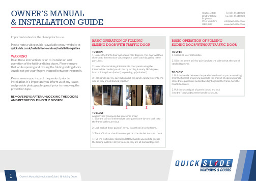
Important notes for the client prior to use.Please note a video guide is available on our website at /installation-services/installation-guides WARNINGRead these instructions prior to installation and operation of the folding-sliding doors. Please ensure that while opening and closing the folding sliding doors you do not get your fingers trapped between the panels.Please ensure you inspect the product prior to installation. It’s important you inform us of any issues and provide photographic proof prior to removing the protection tape.REMOVE KEYS AFTER UNLOCKING THE DOORS AND BEFORE FOLDING THE DOORS!BASIC OPERATION OF FOLDING-SLIDING DOOR WITH TRAFFIC DOORTO OPEN1. Unlock the traffic door and open it 180 degrees. This door will thenclose on to the next door via a magnetic panel catch (supplied in theparts box).2. Unlock the remaining intermediate door panels using theintermediate handle (you do this by turning it nearly 180 degreesfrom pointing down (locked) to pointing up (unlocked).3. Fold panels pair-by-pair sliding all of the panels carefully over to theside so they are all stacked together.TO CLOSEAs described previously but in reverse order;1. Slide the pairs of intermediate door panels one-by-one back in tothe frame so they are shut.2. Lock each of these pairs off as you close them in to the frame.3. The traffic door should remain open and be the last door you close.4. Pull the traffic door closed and lift the handle upwards to engagethe locking system in to the frame.so they are all stacked together.123BASIC OPERATION OF FOLDING-SLIDING DOOR WITHOUT TRAFFIC DOORTO OPEN1. Unlock all internal handles.2. Slide the panels pair-by-pair slowly to the side so that they are allstacked together.TO CLOSE1. Pull the handle between the panels closed so that you are workingfrom the final set of opening panels to the first set of opening panels.Once these panels are pulled back tight against the frame, turn thehandle to secure.2. Pull the second pair of panels closed and lockin to the frame and turn the handle to secure.PREPARATION OF THE OPENINGMake the aperture 15mm wider and 15mm higher than the outside frame size of the unit ordered.Please note that the outside frame height of the required unit is meas-ured from the underside of the sill and NOT FROM THE FINISHED FLOOR LEVEL.IMPORTANT - Due to the large opening sizes, weight and movement of the panels, any application should take into consideration the following;1. The rough opening should be level, plumb and square at all points. There should be no unevenness or bowing. Make sure that the header is not twisted. There should be no bumps on the floor. The sides should be in the same vertical plane and not offset from each other.A telescopic rule and other similar precise measuring equipment should be used to make these determinations.2. The structural integrity of the header is critical for the proper operation. Deflection of the header should be limited to L/720th under full live and dead loads with a maximum deflection limit of 9mm.3. A qualified engineer or architect should be used to determine the proper construction details and header to be used in your particular application.TO AVOID FUTURE PROBLEMS, DO NOT INSTALL THE UNIT UNTIL THE ROUGH OPENING HAS BEEN CORRECTLY PREPARED.HANDLING OF COMPONENTS1. Upon receipt of the products, please carry out a thorough inspection to ensure that all items have been delivered in good suitable condition.2. Store the products in a secure, clean and dry environment and protect against defacement or damage.3. Mark sure that the parts box supplied is not mislaid.ON SITE ASSEMBLYANY DOOR SUPPLIED WITH 4 PANELS OR MORE WILL BE SUPPLIED WITH THE FRAME COMPLETE BUT THE DOOR PANELS SEPERATEANY DOOR SUPPLIED WITH 3 PANELS OR LESS WILL BE SUPPLIED WITH THE DOOR PANELS ALREADY FITTED TO THE OUTER FRAMEGLASS UNITS WILL ALWAYS BY SUPPLIED LOOSEINSTALLATIONS INSTRUCTIONSIMPORTANT - Please ensure that the instructions are fully read and understood prior to beginning the installation of the door.If the installation guide is not followed properly, this could result in the unit not operating correctly.CAUTION - Regulations governing the use of glazed windows, doors, storefronts and/or partitions vary widely. It is the responsibility of the building owner, architect, contractor or installer to insure that products selected confirm to all applicable codes and regulations. Quickslide Ltd. can assume no obligation or responsibility whatsoever for failure of the building owner, architect, contractor or installer to comply with all applicable laws and ordinances and safety and building codes with the exception of CE Marking.PARTS & ANCILLARIES BOX CHECKLISTQUANTITYINSTALLING THE OUTER FRAME (REQUIRES MIN. 2 PEOPLE)1. Remove all door panels from outer frame making a note of each one’s location in the frame. 2 people should lift the outer frame in to the aperture and on to the sill.2. If there is no sill applicable to your order then please refer to the instructions below; a. Create a silicone bed on the masonry for the outer frame to sit on. b. Temporarily secure the frame to the rough opening with clamps.c. Make sure that the frame threshold is packed underneath to make it level and plumb (packers not supplied).3. Pre-drill all fixing points first then fix through the thermal break of the outer frame in to the masonry using suitable frame fixings (not supplied).4. Fix through the thermal break of the outer frame in to the sill at 100mm from each end and 600mm between.5. Before fixing the sides and head, the outer frame should again be packed suitably to ensure it is square and plumb.6. Fixing points should be set 100mm from each corner of the outer frame and then every 600mm between.7. Once the outer frame is fixed in place, it should be level, square and plumb, this should be checked at every 600mm in both width and height using a suitable measuring device.NAME OF PART1 x per hinge (excluding wheels and guides) At least 3 x keys supplied2 x per hinge (including wheels and guide)8 x per glass unit1 x traffic door (supplied with own instructions and fixings)1 x per traffic door 1 x per box 1 x per box 1 x per box 1 x pair per sillSuitable quantity for all panelsExternal hinge plates (black)KeysFirst fix screwsFinal fixing screws (25mm)Toe and Heel glazing packers Magnetic panel catchLifting block and screw (traffic door only)Toe and Heel diagram Allen keySill and caps (if applicable)Glazing gasket (attached to the door or sill)FOR ALL SYSTEMS USE APPROPRIATE SCREW OR OTHER EQUIVALENT ANCHORAGE DEVICES DEPENDING ON THE HEADER MATERIAL AND CONSTRUCTION. ANCHORAGE DEVICES SHOULD PENETRATE OR HOLD SUFFICIENTLY TO THE HEADER TO WITHSTAND NECESSARY STRUCTURAL LOADING.INSTALLING THE SILL1. If the bi-fold has a projecting sill (150, 190 or 225mm) fill the ends with silicone before the end caps go on to prevent a potential leak.2. Fit the sill end caps to the sill using a suitable silicone (not supplied).3. Make a silicone bed on the masonry, sit the sill in to the aperture and pack underneath to make it level, then fix through the thermal break of the sill into the masonry. (Fig 1)4. If the thermal break of the sill sits over a cavity, then you are able to put a fixing through any point of the sill providing that it is covered by the outer frame. We would suggest that you use the thermal break as the first choice fixing point where possible.5. You must ensure that you apply additional silicone sealant to the ends of the sill where it meets the masonry as this will always be the most susceptible point for water ingress.6. When you are ready to sit the outer frame on to the installed sill, you should first run a line of silicone across the internal up-stand of the sill. (Fig 2)12INSTALLING THE DOOR PANELS1. All loose door panels will carry a numerical label which stipulates the order in which they should be fitted in to the outer frame.2. Door ‘1’ will have hinges on one side only which will then connect to the outer frame using the ‘first fix’ screws and external hinge plates (3mm Allen key is included).3. The external hinge plates are first to be located on top of the hinge, as shown (Fig. 1)4. This should be repeated on the remaining hinges on door 1.5. Repeat the above steps fixing door 2 to door 1 etc...Hinge plate, fitted ontop of the main bodyof the hingeMain body of thehinge INSTALLING A DOOR PANEL1. The sliding post will always be hinges to a door panel so this itemdoes not require any additional construction.2. This type of door panel is hinged the same way as a standardpanel but should be fitted in to the outer frame on an angle so thatthe guides are able to clear the outer frame and sit in to the rebatedchannels at the top and bottom of the outer frame.INSTALLING A DOOR PANELWITH WHEELS AND GUIDES1. The wheels and guides will always be attached to the relevant doorpanel and are part of the top and bottom hinge assembly.2. These require hinges unlike the standard ones DO NOT requirehinge plates to be fitted.3. This door panel should be fitted in to the outer frame on an angle sothat the guides and wheels attached to the sliding post are able able toclear the outer frame and sit in to the rebated channels at the top andbottom of the outer frame.Bottom Roller Hinge Top Guide Hinge123FINAL FIXING SCREWS1. Once all of the door panels have been fitted, you should ensure that all of the heads of the door panels ‘line-through’ with each other. (Fig 1)2. Assuming the panels do line-through then you can fit the ‘final fixing screws’ to the centre hole of ALL hinges including rollers and guides. (Fig 2) The final fixing screws need to go in prior to glazing due to the weight of the glass.Final Fixing Screws GLAZINGALL GLAZING SHOULD BE CARRIED OUT BYA COMPETENT GLAZIER. GLAZING PACKERSAS WELL AS A TOE AND HEEL GUIDE HAVEBEEN INCLUDED.1. Remove the pre-glazed beading (4 per sash)keeping track of which bead goes where.2. Follow the toe and heel glazing guide fordetails on packer locations.3. Fit the bottom packers only prior to the glassunits being installed.4. Lift the glass units into the door panel (2people required).5. Fit remaining toe and heel wedge packers.6. Install glazing beads in the relevantlocations.7. Once all 4 sides of the glaz glazing bead havebeen fitted, you will then use the ‘glazing gasket’which will be push-fit between the bead andglass on all 4 sides.8. Repeat on all remaining door panels.FINAL CHECKS1. After installation of the glass units, you shouldcheck the operation of the door to ensure thatit is smooth with no catching door panels. If youfind that a panel is catching you will need toadjust the toe and heel of the relevant glass unit.2. You should have an llmm gap between theedge of the door panel and the edge of theouter frame (gasket line). This is applicable toall 4 sides of the outer frame. (Fig 1)3. You should ensure that all lockingmechanisms operate correctly (traffic doors andintermediate doors).4. There should be no debris or residue in thebottom channel of the outer frame where theroller-bearing wheels are located.ADJUST HINGES1. The hinges can be adjusted up and down usingthe 2.5mm Allen key provided. This is done via agrub screw located on the internal of the hinge.In order for the adjustment to be effective, thefinal fixing screws will need to be removed andthe first fix screws loosened.2. Toe and heel glass units foradjustment on the intermediate doors.12435TOE AND HEELER DEVICE (ACDV295)The Toe and Heeler device comes in 4 seperate parts as shown to the right.a) Adjustment Screw b) Base Plate c) Steel Plate d) Corner PackerThe Base Plate and Adjustment Screw are pre fitted to the sash in the factory.The Steel Plate and Corner Packer will come in the stores package and must be used in place of standard packers in the corners where the device is fitted.TOE & HEEL GLAZING GUIDEBi-fold door sashes are heavy, and although the dead weight is supported on the hinge side there is nothing on the lock side to support the weight. Toe and heeling of each sash is therefore essential to prevent the doors dropping and catching. This is especially a must for frames wider than 1000mm. We recommend following the steps below that explains how to use the device to reinforce the door, which essentially enables the glass to support its own weight.Please note not all doors come with a toe and heeler device and some doors may require conventional toe and heeling.A step-by-step installation video is available on our website at /how-to-install-a-bi-folding-door/WHERE TO FIT THE DEVICE(S)To stop a door sash dropping it needs to be braced diagonally corner to corner by the Toe and Heeler devices between the glass and the frame. On the hinge side of the sash the devices go at the bottom corner, whilst on the lock side they go at the top (opposite corner).Below is an example of where to fit the Toe and Heeler devices, you should use the same principle when glazing other configurations.FITTING WITH A 28MM GLASS UNITThe Toe and Heeler device will require a notch to be cut out when fitting 28mm units to allow the bead to sit in place, as shown below.Please note: Failure to install all of the parts will invalidate the guarantee and could potentially shatter the glass unit.12Step 1: Parts BoxIf your bi-folding doors have been supplied in kit form, you will receive a parts box which include the following:4 x silver tensions blocks per corner (total of 16 per panel)1 x 2.5mm Allen Key2 x final fixing screw per hinge 8 x packers per panels4 x 50mm screws if you’ve opted for a low thresholdLifting block(s) if specifiedFRAME ASSEMBLY FROM KIT FORMIf you’ve requested the frame to be supplied in kit form, you are encouraged to carefully read the below instructions to correctly assemble the outer frame.Step 2: Remove PackagingRemove the outer frame from it’s packaging and lay out the frame on a flat surface working area. The working area should twice the height and width of the door.The bottom of the frame will feature a drainage and steel track.Step 3: Assemble Outer Frame2 of the frame pieces will have 2 metal cleats (see illustration 1). Before assembling the pieces together, you will need to use silicone around the edges to weatherseal the frame. The pieces should then be inserted into the channels. Once inserted place the silver tension blocks in the pre-punched holes.Step 4: GasketThe outer frame will come with a flipper gasket attached. This will need to be pushed in to the groves all the way round the frame.Once the silver tension blocks have been inserted use the 2.5mm Allen key to tighten grub screws making sure surfaces are level.1234。
工厂打滑开关的原理和应用

工厂打滑开关的原理和应用1. 简介工厂打滑开关是一种用于控制工厂生产线的关键设备,它的主要作用是防止生产线因为突发情况而导致设备打滑或停止工作。
本文将介绍工厂打滑开关的原理和应用。
2. 原理工厂打滑开关的工作原理基于传感器技术,它通过感应工厂设备的运行状态,实时监测并判断设备是否发生打滑现象。
当工厂设备运行正常时,打滑开关保持闭合状态,信号传递给控制系统,生产线正常运行。
一旦设备发生打滑或停止工作,打滑开关立即感知到变化,弹簧机构使开关断开,控制系统接收到信号后及时停止工厂生产线,防止进一步损坏设备或产生安全隐患。
3. 应用工厂打滑开关主要应用于以下场景:3.1. 机械制造在机械制造过程中,工厂打滑开关可以安装在关键设备上,如:机床、冲压机、切割机等。
它可以实时监测设备的运行状态,当设备发生打滑现象时,及时停止设备,以保护设备和工人的安全。
3.2. 自动化生产线自动化生产线通常涉及大型设备的运行,例如:装配线、流水线等。
在这些生产线上,打滑开关可以用于监测整条生产线的状态。
如果发现设备打滑或停止工作,打滑开关能够发出信号,通知工作人员及时处理。
3.3. 电力行业在电力行业中,工厂打滑开关常用于大型电力设备,如:汽轮机、发电机组等。
通过安装打滑开关,可以实时监测设备的运行状态,一旦发生打滑或停止工作,打滑开关能够即时切断电源,避免设备故障。
3.4. 物流运输在物流运输中,打滑开关可以用于运输设备,如:输送带、电梯等。
通过安装打滑开关,可以及时发现设备的异常情况,保证物资的安全运输。
4. 优势工厂打滑开关相比传统的开关设备有以下优势:•实时监测:打滑开关能够实时感知设备的运行状态,确保生产线的顺畅运行。
•快速反应:一旦发现设备打滑或停止工作,打滑开关能够快速切断电源,减少设备故障的损失。
•安全保护:打滑开关可以避免设备打滑导致的事故和人员伤害,提供安全保护。
5. 总结工厂打滑开关是一种主要用于控制工厂生产线的关键设备,它通过感应工厂设备的运行状态,实时监测并判断设备是否发生打滑现象。
速关组合件说明书
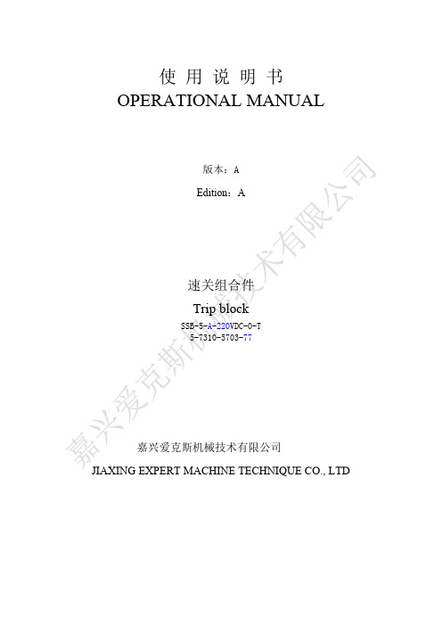
使 用 说 明 书OPERATIONAL MANUAL版本:AEdition:A速关组合件Trip blockSSB-5-A-220VDC-0-T5-7310-5703-77嘉兴爱克斯机械技术有限公司JIAXING EXPERT MACHINE TECHNIQUE CO., LTD1.1说明书的使用1.2开箱检查1.3型号说明1.4技术参数1.5结构功能2. 安装规范2.1速关组合件的就位2.2管道的安装2.3结构图和外形图3. 操作规范3.1打开速关阀和自动挂闸3.2速关阀在线试验3.3遥控停机3.4就地停机3.5危急保安器在线试验3.6原理图4.维护指南1.1说明书的使用● 在安装和使用本产品前请仔细阅读此安装运行说明书,以免给您造成不必要的损失。
1.2 开箱检查● 用户在开箱后,首先应检查文件资料、产品标牌、合格证上所列型号、规格及技术参数是否与订货合同一致,名称、数量与实物是否相符。
● 检查外观表面有无磕碰、划痕,所配零部件有无损伤。
1.3 型号说明S S B-5-A-220V D C-0-T⑴ ⑵ ⑶ ⑷ ⑸⑴ 速关组合件代号⑵ M:就地启动A:远程启动⑶ 表示电磁阀电源220VDC⑷ 表示电磁阀不带电运行⑸ T:带危急保安器在线试验1.4技术参数● 介 质:矿物油● 介质精度:≤30μm● 介质压力:0.5~1.2MPa● 介质温度: -10~70℃● 电磁阀电源: 220VDC● 本体外形尺寸:250×250×3601.5 结构功能速关组合件主要由集块本体,停机电磁阀2222、2223,电磁阀1839,液动阀1830,就地停机阀2250,速关阀试验手动阀2309,危急保安器在线试验阀2070、2080,梭阀2025,组合阀2023、2033,DG40、DG25两通插装阀,在线测压接头P11-P16,支架等组成(详见结构图及原理图)。
其主要用于打开和关闭汽轮机的主汽阀、就地启动、冗余遥控停机、手动停机,速关阀在线试验、危急保安器在线试验、压力表在线测压、自动挂闸等。
- 1、下载文档前请自行甄别文档内容的完整性,平台不提供额外的编辑、内容补充、找答案等附加服务。
- 2、"仅部分预览"的文档,不可在线预览部分如存在完整性等问题,可反馈申请退款(可完整预览的文档不适用该条件!)。
- 3、如文档侵犯您的权益,请联系客服反馈,我们会尽快为您处理(人工客服工作时间:9:00-18:30)。
欠速打滑开关
概述;
欠速打滑开关是一种可靠性强、对轴转速及其他旋转装置简单通用的监测装
置。
当监测到当前转速信号低于正常转速范围开关输出开关信号,以供报警或停
机。
无运动部件、无磨损、安全寿命长,一体化结构,集中的控制装置,设定或
故障检修简单。
安装:
欠速打滑开关安装在输送机从动轮或其他能等于实际胶带运行速度的转轴侧
面,从动轮或转轴侧面需焊接一个可供欠速打滑开关感应面(感应面必须采用铁
质材料),感应面截面尺寸不小于50mm ×50mm ,欠速打滑开关与感应面最大距离
为25mm 。
感应面为欠速打滑开关提供一个脉冲信号,从动轮旋转一圈感应面通过
一次欠速打滑开关区域,从而产生一个脉冲信号。
当产生一次脉冲信号时,欠速
打滑开关面板上的脉冲指示灯会闪一次。
需要确保除感应面外,从动轮侧面无任何可使欠速打滑开关产生脉冲信号的金属物体。
设置:
先按 键出现数码闪烁,再按 键到显示:1、2、3。
再按 键出现数码闪烁,再按 键调整打滑转数值,再按 键设置成功。
工作原理:
欠速打滑开关是为了检测皮带机尾轮的旋转速度,开关与尾轴无接触。
当尾轴随胶带机运行旋转时而带动感应片,感应片与检测器发生的感应信号输入到控制电路中去。
经放大,整形后进行计数,其计数值与预置数比较,从而判断胶带的速度,既:在达到低于打滑速度时执行电路输出相应的开关信号,使主机停机。
本开关可调整速度值。
技术指标:
1、工作电源:AC220V 频率:50-60Hz
2、温度范围:-20℃~+70℃
3、启动延时:约10秒钟
4、检测距离:从检测器到感应块之间最大距离Sn :20mm
5、触点容量:240V/AC ,3A ,输出值一组常开,一组常闭
6、转 速:30-999转/分 第一条 车辆使用范围。
(一)保障领导公
务活动用车。
(二)保障接待合
作伙伴活动用车。
(三)保障全局性业务工作用车和会议会务用车。
SET SET SET SET
123456
(四)各部门负责组织召开的专业性会议,报办公室经主管主任批准后,可安排会务用车。
(五)其他特殊情况经局分管领导批准,可安排用车。
(六)市区内接送任务的车辆原则上不等候,送去车即返回,到时去接。
(七)任何人不得私自占用公车。
第二条用车的手续和批准权限。
(一)为确保安全行车和保证派车的落实,凡需使用车辆的部门,应提前办理用车手续,填写《用车申请及派车单》,经办公室主管主任批准按轻重缓急安排派车,司机凭派车单出车。
办公室应增加车辆调度的透明度。
(二)司机需经办公室主任安排方可出车,不得擅自接受用车事宜。
如遇紧急公务或特殊情况,司机应积极主动出车,事后报告并补办用车手续。
(三)每次出车后由司机在《用车申请及派车单》的相关栏目上如实记录行车实际里程,月终作为司机的工作量和燃油消耗的检查依据。
第三条车辆的维修保养。