STC-200微电脑温度控制器使用说明书
微电脑温控器(SLT-200)说明书

微电脑温控器(SLT-200)使用说明书本产品具有制冷、制热、报警输出模式转换功能,温度控制采用回差方式,用户参数和管理者参数分别设置,并具有压缩机延时可调,温度校正,故障报警,传感器故障后压缩机按预设程序运行等功能。
是一款通用性好,性价比高,适用于冷冻冷藏、海鲜机、热水器等设备和场所的简易控温和报警产品。
规格及技术参数:◆整机尺寸:77.0×34.5×65.5(单位:毫米)◆安装孔尺寸:70.5×28.5(单位:毫米)◆运行环境温度:-5℃~60℃◆贮存温度:-30℃~85℃◆相对湿度:20%~60%(不可结露)◆主要技术参数:电源电压:220VAC±10%(12V±10%可选)电源功耗:5W测温范围:-40℃~99℃控温范围:-40℃~70℃分辨率:1个单位测控温精度:±1℃继电器接点容量:7A/250VAC/30VDC◆主要功能:温度的测量、显示和控制。
温度设定采用回差方式设置。
压缩机延时保护。
故障报警。
制冷、制热、报警可选。
指示灯状态表:闪烁 压缩机延时状态指示灯亮 压缩机工作灭 压缩机停止亮 处于设置状态设置指示灯灭 正常工作参数查看与设置:◆参数查看非设置状态下按"▲"键显示温度设定值,2 秒后显示当前温度;按""键显示回差温度,2秒后显示当前温度。
◆参数设置☆进入用户设置状态:非设置状态下,按"SET"键5秒以上,进入用户设置状态,此时设置指示灯亮,数码管显示当前温度设定值。
☆温度设定:在用户设置状态下,按动"▲"或""键可以向上或向下调整温度设定值。
每按一下调整1℃,按住2秒以上,转为快速调整。
☆退出用户设置状态:用户设置状态下,按"SET"键5秒以上或者30秒内无按键操作,系统保存显示的温度设定值,并返回到正常工作状态。
华宝冷库使用说明书
华宝冷库使用说明书(ECB-10/STC200)欢迎您使用“华宝牌”组合式拼装冷库。
请您在使用本产品之前仔细阅读产品说明书,详细了解冷库的构造和性能,对使用冷库的一些常识要有所了解。
本冷库配置了最为先进的微电脑控制器,只有很好的使用它并将参数设定正确,冷库才能正常高效的工作,您才会享受到高科技带来的方便。
假如你只是囫囵吞枣的看一遍说明书,就迫不及待的使用冷库,将会带来不必要的麻烦。
我们认为你在使用冷库时已经认真的阅读了本说明书。
看好说明书后要妥善放置保管好,以备日后查阅。
为你更好的使用和维护冷库服务。
您在使用本产品的过程中有何建议,请及时与我们联系,以便我们在工作中进一步改进和完善。
谢谢合作!一、冷库安装前的准备工作•冷库设备安放在通风良好的干燥洁净环境中。
禁止在易燃、易爆、易腐蚀、有破坏绝缘的气体和导电尘埃的环境中使用本设备,禁止在不安全或有安全隐患的环境中使用本设备。
冷库安装之前,三相四线电源一定要到位。
•应有足够的空间进行冷库设备的安装,地面用混凝土抹面找平,一定要保证地面水平,以确保冷库拼装的整体效果。
地面耐力不小于3T/m2。
地面预留排水孔或槽。
•冷库使用的电源为三相四线380V/50Hz(±10%),检查使用的电源是否与设备配套。
线载负荷是否符合要求而满足设备的的正常运行。
并配备冷库专用保护电闸。
•冷库设备一般配用风冷式冷凝器,不需要用水,特别适用于边远地区和缺水地区使用。
(有些情况下用户要求用水冷式冷凝器,此时用户要配置水池或水井)•冷库设备应有专人负责看管。
并了解用电常识和熟悉冷库的基本构造、性能。
二冷库设备的安装先检查设备的外包装是否破损。
拆箱后对照装箱单检查所有随机文件和配件是否齐全。
检查机器的零部件是否因长途运输、搬运而松动、破损。
用户根据厂方提供的图纸和安装说明书进行安装调试。
当用户对冷库的常识不甚了解或对冷库安装毫无把握时,可与厂方达成协议,由厂方为您提供有偿服务。
温控仪使用说明范文
温控仪使用说明范文一、温控仪概述温控仪是一种用于控制温度的智能设备,能够实时监测温度,并通过控制其他设备来达到设定的温度值。
温控仪广泛应用于家庭、办公室、工厂等场所,可用于控制空调、取暖设备、温水器等。
二、温控仪的外观和结构温控仪外观通常为方形或圆形,大小约为手掌大小。
表面通常有一个液晶显示屏,用于显示当前温度和设定温度。
温控仪底部有一个插槽,可以插入电源适配器。
另外,温控仪上还有几个键,用于设置温度和其他参数。
三、温控仪的基本功能1.温度监测:温控仪内置温度传感器,可实时检测当前温度,并将其显示在液晶屏上。
2.温度控制:温控仪可以通过控制其他设备来调节房间温度。
用户可以通过设置温度来达到舒适的温度。
3.定时功能:温控仪也具备定时功能,用户可以设置开机和关机的时间,避免长时间浪费电能。
4.温度预警:当环境温度低于或高于设定的温度范围时,温控仪会发出声音或报警光,提醒用户调整温度。
5.节能功能:温控仪可以根据用户的使用习惯和室内外温度情况自动调整工作模式,以达到节能的目的。
四、温控仪的使用步骤1.将温控仪插入电源适配器,然后将电源适配器插入电源插座。
2.按下电源键,温控仪会自检并显示当前温度。
3.使用上下键或旋转键来设置目标温度,然后按下确认键确认设置。
4.温控仪会显示当前温度和目标温度,并自动控制其他设备来达到设定温度。
5.如果需要设置定时功能,可以按下设置定时键,然后按照屏幕提示进行操作。
6.当环境温度超出设定温度范围时,温控仪会自动发出声音或报警光,提醒用户调整温度。
7.当需要关闭温控仪时,长按电源键,温控仪将停止工作并关机。
五、常见问题解答1.温控仪为什么显示的温度和实际温度不一致?答:温控仪通常采用内部测温方法,所以会受到周围环境的影响。
建议将温控仪放置在离地面1.5米左右的位置,尽量避免阳光直射或近距离热源。
2.温控仪为什么不能控制其他设备?答:请检查温控仪和其他设备之间的连接是否正确,并确保其他设备已经接通电源。
温控器说明书
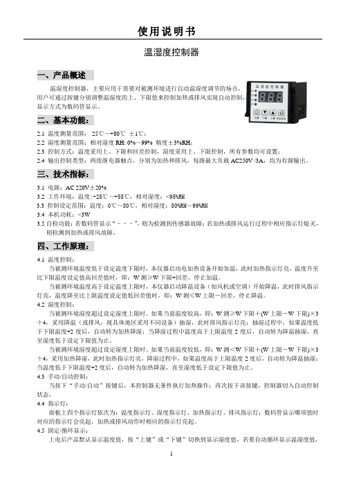
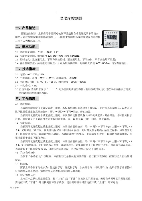
温湿度控制器一、产品概述温湿度控制器,主要应用于需要对被测环境进行自动温湿度调节的场合,用户可通过按键分别调整温湿度的上、下限值来控制加热或排风实现自动控制,显示方式为数码管显示。
二、基本功能:2.1 温度测量范围:-25℃~+80℃±1℃;2.2 湿度测量范围:相对湿度RH: 0%~99% 精度±3%RH;2.3 控制方式:温度采用上、下限和回差控制,湿度采用上、下限控制,所有参数均可设置;2.4 输出控制类型:两组继电器触点,分别为加热和排风,每路最大负载AC250V /3A,均为有源输出。
三、技术指标:3.1电源:AC 220V±20%3.2 工作环境:温度:-25℃~+55℃,相对湿度:<95%RH3.3控制设定范围:温度:0℃~80℃,相对湿度:50%RH~99%RH3.4 本机功耗:<3W3.5自检功能:若数码管显示“–––”,则为检测到传感器故障;若加热或排风运行过程中相应指示灯熄灭,则检测到加热或排风故障。
四、工作原理:4.1 温度控制:当被测环境温度低于设定温度下限时,本仪器启动电加热设备开始加温,此时加热指示灯亮,温度升至比下限温度设定值高回差值时,即:W测≥W下限+回差,停止加温。
当被测环境温度高于设定温度上限时,本仪器启动降温设备(如风机或空调)开始降温,此时排风指示灯亮,温度降至比上限温度设定值低回差值时,即:W测≤W上限-回差,停止降温。
4.2 湿度控制:当被测环境湿度超过设定湿度上限时。
如果当前温度较高,即:W测≥W下限+(W上限-W下限)×3÷4,采用降温(或排风,视具体地区采用不同设备)抽湿,此时排风指示灯亮;抽湿过程中,如果温度低于下限温度+2度后,自动转为加热降湿;当降湿过程中温度高于上限温度-2度后,自动转为降温抽湿,直至湿度低于设定下限值为止。
当被测环境湿度超过设定湿度上限时。
如果当前温度较低,即:W测<W下限+(W上限-W下限)×3÷4,采用加热降湿,此时加热指示灯亮,降湿过程中,如果温度高于上限温度-2度后,自动转为降温抽湿;当温度低于下限温度+2度后,自动转为加热降湿,直至湿度低于设定下限值为止。
温控器说明书
温湿度控制器一、产品概述温湿度控制器,主要应用于需要对被测环境进行自动温湿度调节的场合,用户可通过按键分别调整温湿度的上、下限值来控制加热或排风实现自动控制,显示方式为数码管显示。
二、基本功能:2.1 温度测量范围:-25℃~+80℃±1℃;2.2 湿度测量范围:相对湿度RH: 0%~99% 精度±3%RH;2.3 控制方式:温度采用上、下限和回差控制,湿度采用上、下限控制,所有参数均可设置;2.4 输出控制类型:两组继电器触点,分别为加热和排风,每路最大负载AC250V /3A,均为有源输出。
三、技术指标:3.1电源:AC 220V±20%3.2 工作环境:温度:-25℃~+55℃,相对湿度:<95%RH3.3控制设定范围:温度:0℃~80℃,相对湿度:50%RH~99%RH3.4 本机功耗:<3W3.5自检功能:若数码管显示“–––”,则为检测到传感器故障;若加热或排风运行过程中相应指示灯熄灭,则检测到加热或排风故障。
四、工作原理:4.1 温度控制:当被测环境温度低于设定温度下限时,本仪器启动电加热设备开始加温,此时加热指示灯亮,温度升至比下限温度设定值高回差值时,即:W测≥W下限+回差,停止加温。
当被测环境温度高于设定温度上限时,本仪器启动降温设备(如风机或空调)开始降温,此时排风指示灯亮,温度降至比上限温度设定值低回差值时,即:W测≤W上限-回差,停止降温。
4.2 湿度控制:当被测环境湿度超过设定湿度上限时。
如果当前温度较高,即:W测≥W下限+(W上限-W下限)×3÷4,采用降温(或排风,视具体地区采用不同设备)抽湿,此时排风指示灯亮;抽湿过程中,如果温度低于下限温度+2度后,自动转为加热降湿;当降湿过程中温度高于上限温度-2度后,自动转为降温抽湿,直至湿度低于设定下限值为止。
当被测环境湿度超过设定湿度上限时。
如果当前温度较低,即:W测<W下限+(W上限-W下限)×3÷4,采用加热降湿,此时加热指示灯亮,降湿过程中,如果温度高于上限温度-2度后,自动转为降温抽湿;当温度低于下限温度+2度后,自动转为加热降湿,直至湿度低于设定下限值为止。
STC-100A微电脑温度控制器说明书
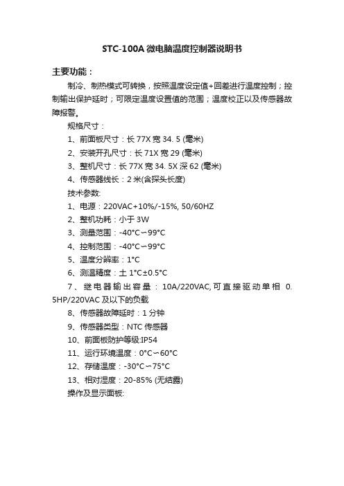
STC-100A微电脑温度控制器说明书主要功能:制冷、制热模式可转换,按照温度设定值+回差进行温度控制;控制输出保护延时;可限定温度设置值的范围;温度校正以及传感器故障报警。
规格尺寸:1、前面板尺寸:长77X宽34. 5 (毫米)2、安装开孔尺寸:长71X宽29 (毫米)3、整机尺寸:长77X宽34. 5X深62 (毫米)4、传感器线长:2米(含探头长度)技术参数:1、电源:220VAC+10%/-15%, 50/60HZ2、整机功耗:小于3W3、测量范围:-40°C〜99°C4、控制范围:-40°C〜99°C5、温度分辨率:1°C6、测温精度:土1°C±0.5°C7、继电器输出容量:10A/220VAC,可直接驱动单相0. 5HP/220VAC及以下的负载8、传感器故障延时:1分钟9、传感器类型:NTC传感器10、前面板防护等级:IP5411、运行环境温度:0°C〜60°C12、存储温度:-30°C〜75°C13、相对湿度:20-85% (无结露)操作及显示面板:显示说明:两位红色数码管显示温度等信息。
按键说明:▲键:上调键;▼键:下调键;set键:设置键。
指示灯状态说明:按键操作说明:1、修改温度设定值:控制器正常工作时,按下set键显示当前温度设定值,此时按▲键或▼键可上调或下调并显示温度设定值。
4秒内没有任何按键操作则保存参数修改并返回正常显示状态。
保存参数时如果出现错误则显示'Er',3秒后返回正常显示状态。
2、修改参数设定值:控制器正常工作时,按住set键持续4秒以上进入修改参数模式,显示第一个菜单项的代码'HC'。
按▲键或▼键可上翻或下翻菜单项并显示菜单项的代码,按set键显示当前菜单的参数设定值。
按住set键不放,再按▲键或▼键可上调或下调并显示当前菜单的参数设定值。
可编程温度控制器使用方法
可编程温度控制器使用方法一、可编程温度控制器的初步认识。
1.1 这可编程温度控制器啊,就像是一个温度的小管家。
你看它,外观上可能有个显示屏,能让你直观地看到各种信息呢。
它的大小不一,但都很精巧,摆在那儿就像个默默守护温度的小卫士。
1.2 它的功能可强大啦。
不像那些普通的温度控制设备,只能简单地调个温度。
这个可编程的家伙,可以按照你设定的程序来控制温度,就像你给它下了一道道指令,它就乖乖听话。
二、开始使用前的准备。
2.1 首先呢,你得把它安装好。
这就跟盖房子打地基似的,安装的地方得合适。
要找个通风良好、干燥的地方,可不能让它受潮或者被什么东西捂着,不然它就像人被捂住了嘴,没法好好工作啦。
2.2 接着就是连接电源。
这一步可不能马虎,就像给手机充电得插对线一样。
要确保电源连接稳定,电压得符合它的要求,不然它就会像个闹脾气的小孩,工作起来不正常。
2.3 然后就是传感器的安装。
传感器就像是它的小触角,用来感知温度的。
你得把传感器安装在能准确测量温度的地方,要是装错了地方,那它得到的温度信息就不准确,整个控制就会乱了套,这就叫“差之毫厘,谬以千里”啊。
三、设定温度程序。
3.1 进入到设定程序这一步,就像你在教小孩子做事情一样。
你得先选择模式,有制冷模式、制热模式等。
比如说你想让一个小空间保持凉爽,那就选择制冷模式。
这时候你要根据实际需求来设定目标温度,不能太贪心,温度设得太低或者太高都不合适,要恰到好处,就像炒菜放盐,不多不少才正好。
3.2 再就是设定时间程序。
你可以设定它在某个时间段内保持某个温度。
比如说你想在晚上睡觉时让房间保持温暖,你就可以设定从晚上10点到早上6点保持一个舒适的温度。
这就像给它定了个闹钟,到点就按照你的要求来控制温度。
四、使用中的注意事项。
4.1 在它工作的时候,你要时不时地去看看它。
就像照顾小宠物一样,看看显示屏上的温度是不是在正常范围内。
如果发现有什么异常,可不能坐视不管,要赶紧检查是哪里出了问题。
温控仪操作说明范文
温控仪操作说明范文第一部分:产品介绍温控仪是一种用于测量和控制温度的设备,广泛应用于各种家用和工业领域。
它通过传感器感知环境温度,并通过控制装置调整加热和冷却设备的工作,以维持设定的温度范围。
本操作说明将详细介绍温控仪的功能、使用方法和注意事项,以帮助用户正确操作和维护温控仪。
第二部分:功能说明1.温度测量:温控仪配备了高精度温度传感器,可准确测量环境温度。
2.温度控制:通过设定目标温度和温度调节范围,温控仪可以自动控制加热和冷却设备的工作,以保持设定温度范围内的稳定温度。
3.温度显示:温控仪的显示屏可以实时显示环境温度和设定温度,方便用户随时了解当前温度情况。
4.报警功能:当环境温度超出设定温度范围时,温控仪会发出声音和闪烁警示灯,提醒用户温度异常。
第三部分:使用方法1.连接设备:将温控仪与加热和冷却设备进行连接。
确保连接稳固可靠,并按照设备说明书连接正确。
2.打开电源:将温控仪插入电源插座,并按下电源按钮,待显示屏亮起后即可正常使用。
3.设置温度范围:通过操作控制面板上的按钮,设定目标温度和温度调节范围。
确保设定范围合理,并根据需要进行调整。
4.启用温控功能:按下温控功能按钮,开始温控仪的自动工作。
此时,温控仪将根据设定的温度范围来调整加热和冷却设备的工作。
5.监测温度:通过显示屏上的数字显示,用户可以实时监测环境温度和设定温度。
确保温度符合要求,并根据需要进行调整。
6.注意报警:如果温控仪发出警示声音和闪烁灯光,表明环境温度已经超出设定的温度范围。
此时,用户应立即检查设备,确认问题原因,并采取相应措施。
第四部分:注意事项1.安装位置:温控仪应安装在通风良好、避免阳光直射和有较少振动的地方,以确保传感器和仪器的稳定工作。
2.周围环境:避免将温控仪暴露在高温、高湿度、腐蚀性气体等恶劣环境中,以免损坏设备。
3.温度范围:确保设定的温度范围合理,如果超出温控仪的最大测量范围或控制范围,可能导致温控仪无法正常工作。
ETC-200温控器说明书
R
电器
R
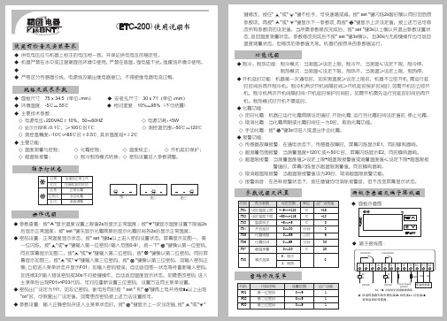
微电脑温控器(ETC-200)使用说明书
使用前检查及安装要求
◆ 供电电压应与机器上标注的电压相一致,并保证供电电压的稳定性。 ◆ 机器严禁在水中或过渡潮湿的环境中使用,严禁在高温、强电磁干扰、强腐蚀环境中使用。 ◆ 传感器采用美国DALLAS集成温度传感器,接线时严格按接线图要求,否则会损坏传感器。 ◆ 严格区分传感器引线,电源线及输出继电器接口,不得使继电器电流过载。
库温传感器
K1、K2 为驱动交流接触器绕组。
★ 库温传感器引线中黑色接10,白色接11,红色接12, 否则会损坏传感器。
F08 模式选择
设定范围 -49~+120 -50~+119 -5~+5
0~30 0~99 0~99 0~20 0:制冷 1:制热
单位 ℃ ℃ ℃
分钟 小时 分钟
℃
出厂设定值 -15 -18 0 3 6 30 20
0
密码修改菜单
代码 P01 P02 P03
代码说明 第一位密码 第二位密码 第三位密码
功能说明
◆ 制冷、制热功能:制冷模式:当测温≥设定上限,制冷开,当测温≤设定下限,制冷停。 制热模式:当测温≤设定下限,制热开,当测温≥设定上限,制热停。
C型温控器功能说明及使用

C型温控器功能说明及使用首先,C型温控器具备温度测量功能。
它内置了温度传感器,可以准确地测量环境温度。
通过显示屏,用户可以实时了解当前温度,并根据需要进行相应的调节。
其次,C型温控器拥有温度控制功能。
用户可以预设一个目标温度值,温控器会根据当前环境温度与目标温度之间的差距,自动调节工作状态,以达到目标温度。
通过温度控制功能,用户可以保持恒温状态,提供一个舒适的环境。
另外,C型温控器还具备定时功能。
用户可以设置一个时间段,在这个时间段内,温控器会按照预设的温度进行工作。
例如,用户可以在夜间设定较低的温度,以节约能源,提供更好的睡眠环境。
C型温控器还可与其他设备进行联动。
例如,它可以和空调、暖气等设备连接,实现自动控温。
当环境温度偏离目标温度时,温控器会发送信号给其他设备,以启动或停止工作。
这种联动功能不仅可以提高能源利用率,还可以提供更加智能化的温控方案。
此外,C型温控器还具备故障报警功能。
当温控器出现故障或异常情况时,它会发出声音或显示警示信息,提醒用户进行检修或更换设备。
这种报警功能可以及时发现问题,避免温度控制出现大的波动或安全隐患。
C型温控器的使用方法也非常简单。
首先,将温控器插入电源,并连接需要控制温度的设备。
然后,通过操作面板上的按键或旋钮,设置目标温度和工作时间段。
温控器将自动开始工作,并根据设定的参数进行温度控制。
如果需要修改参数,用户只需按照菜单提示进行操作即可。
需要注意的是,在使用C型温控器时,应根据实际需求合理设置参数。
例如,冬季使用时,可以将温度调高一些,而夏季使用时,可以将温度调低一些,以达到舒适的温度控制效果。
此外,使用时还应注意温控器的安装位置,避免阳光直射或受到其他干扰,影响测量和控制的准确性。
总之,C型温控器是一款功能齐全、操作简便的温度控制设备。
它可以测量温度,控制温度,具备定时和报警功能,可与其他设备联动,为用户提供舒适的温控体验。
使用时,只需简单设置参数,即可实现自动温度控制,满足不同场所的需求。
温度控制设备操作指南说明书

Field settings table[6.8.2] = .... ID66F2*BLQ05CAV3*DLQ05CAV3*BLQ07CAV3*DLQ07CAV3(*1)*B*(*2)*D*4P405542-1A - 2017.047.4.1.1R/W [3-07]~[3-06], step: A.3.2.421°C7.4.1.2R/W [3-07]~[3-06], step: A.3.2.419°C7.4.1.3R/W [3-08]~[3-09], step: A.3.2.424°C7.4.1.4R/W[3-08]~[3-09], step: A.3.2.426°C7.4.2.1[8-09]R/W [9-01]~[9-00], step: 1°C 45°C7.4.2.2[8-0A]R/W [9-01]~[9-00], step: 1°C 40°C7.4.2.3[8-07]R/W [9-03]~[9-02], step: 1°C 18°C7.4.2.4[8-08]R/W [9-03]~[9-02], step: 1°C 20°C7.4.2.5R/W -10~10°C, step: 1°C 0°C7.4.2.6R/W -10~10°C, step: 1°C -2°C7.4.2.7R/W -10~10°C, step: 1°C 0°C7.4.2.8R/W-10~10°C, step: 1°C 2°C7.4.3.1[6-0A]R/W 30~[6-0E]°C, step: 1°C 55°C7.4.3.2[6-0B]R/W 30~min(50, [6-0E])°C, step: 1°C 45°C7.4.3.3[6-0C]R/W30~min(50, [6-0E])°C, step: 1°C 45°C 7.4.4R/W0: Level 11: Level 22: Level 37.4.5.1[C-0C][D-0C]R/W 0,00~990/kWh 0/kWh7.4.5.2[C-0D][D-0D]R/W 0,00~990/kWh 0/kWh7.4.5.3[C-0E][D-0E]R/W0,00~990/kWh 0/kWh 7.4.6R/W0,00~990/kWh 0,00~290/MBtu 8,0/kWh7.7.1.1[1-00]Set weather-dependent heating Low ambient temp. for LWT main zone heatingWD curve.R/W -40~5°C, step: 1°C-10°C7.7.1.1[1-01]Set weather-dependent heating High ambient temp. for LWT main zone heatingWD curve.R/W 10~25°C, step: 1°C 15°C7.7.1.1[1-02]Set weather-dependent heating Leaving water value for low ambient temp. forLWT main zone heating WD curve.R/W [9-01]~[9-00]°C, step: 1°C 45°C7.7.1.1[1-03]Set weather-dependent heating Leaving water value for high ambient temp. forLWT main zone heating WD curve.R/W[9-01]~min(45, [9-00])°C , step: 1°C 35°C7.7.1.2[1-06]Set weather-dependent cooling Low ambient temp. for LWT main zone coolingWD curve.R/W 10~25°C, step: 1°C 20°C7.7.1.2[1-07]Set weather-dependent cooling High ambient temp. for LWT main zone coolingWD curve.R/W 25~43°C, step: 1°C 35°C7.7.1.2[1-08]Set weather-dependent cooling Leaving water value for low ambient temp. forLWT main zone cooling WD curve.R/W [9-03]~[9-02]°C, step: 1°C 22°C7.7.1.2[1-09]Set weather-dependent cooling Leaving water value for high ambient temp. forLWT main zone cooling WD curve.R/W[9-03]~[9-02]°C, step: 1°C 18°C7.7.2.1[0-00]Set weather-dependent heating Leaving water value for high ambient temp. forLWT add zone heating WD curve.R/W [9-05]~min(45,[9-06])°C, step: 1°C 35°C7.7.2.1[0-01]Set weather-dependent heating Leaving water value for low ambient temp. forLWT add zone heating WD curve.R/W [9-05]~[9-06]°C, step: 1°C 45°C7.7.2.1[0-02]Set weather-dependent heating High ambient temp. for LWT add zone heatingWD curve.R/W 10~25°C, step: 1°C 15°C7.7.2.1[0-03]Set weather-dependent heating Low ambient temp. for LWT add zone heatingWD curve.R/W-40~5°C, step: 1°C -10°C7.7.2.2[0-04]Set weather-dependent cooling Leaving water value for high ambient temp. forLWT add zone cooling WD curve.R/W [9-07]~[9-08]°C, step: 1°C 8°C7.7.2.2[0-05]Set weather-dependent cooling Leaving water value for low ambient temp. forLWT add zone cooling WD curve.R/W [9-07]~[9-08]°C, step: 1°C 12°C7.7.2.2[0-06]Set weather-dependent cooling High ambient temp. for LWT add zone coolingWD curve.R/W 25~43°C, step: 1°C 35°C7.7.2.2[0-07]Set weather-dependent cooling Low ambient temp. for LWT add zone coolingWD curve.R/W10~25°C, step: 1°C 20°CA.2.1.1[E-00]R/O 0~52: Monobloc A.2.1.2[E-01]R/O 0~10: 8A.2.1.3[E-02]R/O 0: Type 1 (*1)1: Type 2 (*2)A.2.1.7[C-07]R/W0: LWT control 1: Ext RT control 2: RT control A.2.1.8[7-02]R/W 0: 1 LWT zone 1: 2 LWT zones A.2.1.9[F-0D]R/W0: Continuous 1: Sample 2: Request A.2.1.A [E-04]R/O0: No 1: YesIndoor software type Unit control methodNumber of LWT zones Pump operation modePower saving possible HighMedium Low Unit type Compressor type Comfort (cooling)Eco (cooling)Storage comfortStorage eco Reheat Comfort (heating)Eco (heating)Comfort (cooling)Eco (cooling)Comfort (heating)Eco (heating)Comfort (heating)Eco (heating)Comfort (cooling)Eco (cooling) 4P405542-1A - 2017.04(*1) *B*_(*2) *D*A.2.1.B R/W 0: At unit 1: In room A.2.1.C[E-0D]Glycol present R/W0: No 1: YesA.2.2.A [D-02]R/W0: No1: Secondary rtrn 2: Disinf. Shunt 3: Circul. Pump 4: CP & disinf. Sh A.2.2.B [C-08]R/W0: No1: Outdoor sensor 2: Room sensor A.2.2.E.1[E-03]R/W0: No BUH 1: 1 step 2: 2 steps A.2.2.E.2[5-0D]R/W0~51: 1P,(1/1+2)4: 3PN,(1/2)5: 3PN,(1/1+2)A.2.2.E.3[D-01]R/W0: No1: Open tariff 2: Closed tariff A.2.2.E.4[E-05]R/W 0: No 1: YesA.2.2.E.5[C-05]R/W 1: Thermo ON/OFF 2: C/H request A.2.2.E.6[C-06]R/W0~21: Thermo ON/OFF A.2.2.F.1[C-02]R/W0: No1: Bivalent 2: -3: -A.2.2.F.2[C-09]R/W 0: Normally open 1: Normally closed A.2.2.F.3[D-08]R/W0: No1: 0,1 pulse/kWh 2: 1 pulse/kWh 3: 10 pulse/kWh 4: 100 pulse/kWh 5: 1000 pulse/kWh A.2.2.F.4[D-09]R/W0: No1: 0,1 pulse/kWh 2: 1 pulse/kWh 3: 10 pulse/kWh 4: 100 pulse/kWh 5: 1000 pulse/kWh A.2.2.F.5[C-08]R/W0: No1: Outdoor sensor 2: Room sensor A.2.2.F.6[D-04]R/W0: No 1: YesA.2.3.1[6-02]R/W 0~10kW, step: 0,2kW 3kWA.2.3.2[6-03]R/W 0~10kW, step: 0,2kW 3kWA.2.3.3[6-04]R/W0~10kW, step: 0,2kW 0kWA.3.1.1.1R/W0: Fixed1: Weather dep.2: Fixed + scheduled 3: WD + scheduled A.3.1.1.2.1[9-01]Temperature range Minimum temp (heating)R/W 15~37°C, step: 1°C 25°CA.3.1.1.2.2[9-00]Temperature range Maximum temp (heating)R/W 37~55°C, step: 1°C 55°CA.3.1.1.2.3[9-03]Temperature range Minimum temp (cooling)R/W 5~18°C, step: 1°C 5°CA.3.1.1.2.4[9-02]Temperature range Maximum temp (cooling)R/W 18~22°C, step: 1°C 22°C A.3.1.1.5[8-05]R/W 0: No 1: Yes A.3.1.1.7[9-0B]R/W0: Quick 1: SlowA.3.1.2.1R/W0: Fixed1: Weather dep.2: Fixed + scheduled 3: WD + scheduled A.3.1.2.2.1[9-05]Temperature range Minimum temp (heating)R/W 15~37°C, step: 1°C 25°CA.3.1.2.2.2[9-06]Temperature range Maximum temp (heating)R/W 37~55°C, step: 1°C 55°CA.3.1.2.2.3[9-07]Temperature range Minimum temp (cooling)R/W 5~18°C, step: 1°C 5°CA.3.1.2.2.4[9-08]Temperature rangeMaximum temp (cooling)R/W18~22°C, step: 1°C 22°CA.3.1.3.1[9-09]R/W 3~10°C, step: 1°C 5°CA.3.1.3.2[9-0A]R/W3~10°C, step: 1°C 5°CA.3.2.1.1[3-07]Room temp. rangeMinimum temp (heating)R/W 12~18°C, step: A.3.2.416°CA.3.2.1.2[3-06]Room temp. range Maximum temp (heating)R/W 18~30°C, step: A.3.2.430°CA.3.2.1.3[3-09]Room temp. range Minimum temp (cooling)R/W 15~25°C, step: A.3.2.415°CA.3.2.1.4[3-08]Room temp. rangeMaximum temp (cooling)R/W25~35°C, step: A.3.2.435°CExternal kWh meter 1External kWh meter 2External sensor PCC by digital inputs Backup heater stepsBUH type Preferential kWh rate DHW operation Contact type main Contact type add.BUH: step 1BUH: step 2LWT setpoint modeModulated LWT Emitter typeLWT setpoint modeHeating CoolingUser interface location DHW pumpExternal sensor Booster heaterExt. backup heat srcAlarm output (*1) *B*_(*2) *D* 4P405542-1A - 2017.04A.3.2.2[2-0A]R/W -5~5°C, step: 0,5°C 0°CA.3.2.3[2-09]R/W -5~5°C, step: 0,5°C 0°CA.3.2.4R/W0: 0,5 °C 1: 1 °CA.3.3.1[4-02]R/W 14~35 °C, step: 1°C 25°CA.3.3.2[F-01]R/W10~35°C, step: 1°C 20°CA.4.1[6-0D]R/W0: Reheat only1: Reheat + sched.2: Scheduled only A.4.4.1[2-01]R/W 0: No 1: YesA.4.4.2[2-00]R/W0: Each day 1: Monday 2: Tuesday 3: Wednesday 4: Thursday 5: Friday 6: Saturday 7: SundayA.4.4.3[2-02]R/W 0~23 hour, step: 1 hour 23A.4.4.4[2-03]R/W 55~80°C, step: 5°C 70°CA.4.4.5[2-04]R/W5~60 min, step: 5 min 10 minA.4.5[6-0E]R/W40~80°C, step: 1°C 60°CA.4.6R/W0: Fixed1: Weather dep.A.4.7[0-0B]Weather-dependent curveLeaving water value for high ambient temp. for DHW WD curve.R/W 35~[6-0E]°C, step: 1°C 55°CA.4.7[0-0C]Weather-dependent curve Leaving water value for low ambient temp. for DHW WD curve.R/W 45~[6-0E]°C, step: 1°C 60°CA.4.7[0-0D]Weather-dependent curve High ambient temp. for DHW WD curve.R/W 10~25°C, step: 1°C 15°CA.4.7[0-0E]Weather-dependent curveLow ambient temp. for DHW WD curve.R/W-40~5°C, step: 1°C -10°CA.5.1.1[4-00]R/W0~20: Disabled 1: Enabled A.5.1.3[4-07]R/W 0: No 1: YesA.5.1.4[5-01]R/W-15~35°C, step: 1°C -4°CA.6.1[3-00]R/W0: No 1: Yes A.6.2.1[D-00]R/W0: None 1: BSH only 2: BUH only 3: All heaters A.6.2.2[D-05]R/W0: Forced off 1: As normalA.6.3.1[4-08]R/W0: No limitation 1: Continuous 2: Digital inputs A.6.3.2[4-09]R/W 0: Current 1: PowerA.6.3.3[5-05]R/W 0~50 A, step: 1 A 50 AA.6.3.4[5-09]R/W 0~20 kW, step: 0,5 kW 20 kWA.6.3.5.1[5-05]Amp. limits for DI Limit DI1R/W 0~50 A, step: 1 A 50 AA.6.3.5.2[5-06]Amp. limits for DI Limit DI2R/W 0~50 A, step: 1 A 50 AA.6.3.5.3[5-07]Amp. limits for DI Limit DI3R/W 0~50 A, step: 1 A 50 AA.6.3.5.4[5-08]Amp. limits for DI Limit DI4R/W 0~50 A, step: 1 A 50 AA.6.3.6.1[5-09]kW limits for DI Limit DI1R/W 0~20 kW, step: 0,5 kW 20 kWA.6.3.6.2[5-0A]kW limits for DI Limit DI2R/W 0~20 kW, step: 0,5 kW 20 kWA.6.3.6.3[5-0B]kW limits for DI Limit DI3R/W 0~20 kW, step: 0,5 kW 20 kWA.6.3.6.4[5-0C]kW limits for DI Limit DI4R/W 0~20 kW, step: 0,5 kW 20 kW A.6.3.7[4-01]R/W0: None 1: BSH 2: BUHA.6.4[1-0A]R/W0: No averaging 1: 12 hours 2: 24 hours 3: 48 hours 4: 72 hours A.6.5[2-0B]R/W-5~5°C, step: 0,5°C 0°CType Amp. value kW value PriorityEnable BUH step 2Equilibrium temp.Allowed heatersForced pump OFF ModeTemperature target DurationOperation mode Ext. room sensor offset Space heating OFF tempDisinfectionOperation dayStart timeRoom temp. step Space cooling On tempRoom temp. offset 4P405542-1A - 2017.04(*1) *B*_(*2) *D*A.6.A[7-05]R/W0: Very high 1: High 2: Medium 3: Low 4: Very low A.6.CR/W0: Manual 1: AutomaticA.8[0-00]R/W [9-05]~min(45,[9-06])°C, step: 1°C 35°CA.8[0-01]R/W [9-05]~[9-06]°C, step: 1°C 45°CA.8[0-02]R/W 10~25°C, step: 1°C 15°CA.8[0-03]R/W -40~5°C, step: 1°C -10°CA.8[0-04]R/W [9-07]~[9-08]°C, step: 1°C 8°CA.8[0-05]R/W [9-07]~[9-08]°C, step: 1°C 12°CA.8[0-06]R/W 25~43°C, step: 1°C 35°CA.8[0-07]R/W 10~25°C, step: 1°C 20°CA.8[0-0B]R/W 35~[6-0E]°C, step: 1°C 55°CA.8[0-0C]R/W 45~[6-0E]°C, step: 1°C 60°CA.8[0-0D]R/W 10~25°C, step: 1°C 15°CA.8[0-0E]R/W -40~5°C, step: 1°C -10°CA.8[1-00]R/W -40~5°C, step: 1°C -10°CA.8[1-01]R/W 10~25°C, step: 1°C 15°CA.8[1-02]R/W [9-01]~[9-00], step: 1°C 45°CA.8[1-03]R/W [9-01]~min(45, [9-00])°C , step: 1°C 35°CA.8[1-04]R/W 0: Disabled 1: Enabled A.8[1-05]R/W 0: Disabled 1: EnabledA.8[1-06]R/W 10~25°C, step: 1°C 20°CA.8[1-07]R/W 25~43°C, step: 1°C 35°CA.8[1-08]R/W [9-03]~[9-02]°C, step: 1°C 22°CA.8[1-09]R/W [9-03]~[9-02]°C, step: 1°C 18°CA.8[1-0A]R/W0: No averaging 1: 12 hours 2: 24 hours 3: 48 hours 4: 72 hours A.8[2-00]R/W0: Each day 1: Monday 2: Tuesday 3: Wednesday 4: Thursday 5: Friday 6: Saturday 7: Sunday A.8[2-01]R/W 0: No 1: YesA.8[2-02]R/W 0~23 hour, step: 1 hour 23A.8[2-03]R/W 55~80°C, step: 5°C 70°CA.8[2-04]R/W 5~60 min, step: 5 min 10 minA.8[2-05]R/W 4~16°C, step: 1°C 16°CA.8[2-06]R/W 0: Disabled 1: EnabledA.8[2-09]R/W -5~5°C, step: 0,5°C 0°CA.8[2-0A]R/W -5~5°C, step: 0,5°C 0°CA.8[2-0B]R/W -5~5°C, step: 0,5°C 0°C A.8[3-00]R/W0: No 1: Yes A.8[3-01]0A.8[3-02]1A.8[3-03]4A.8[3-04]2A.8[3-05]1A.8[3-06]R/W 18~30°C, step: A.3.2.430°CA.8[3-07]R/W 12~18°C, step: A.3.2.416°CA.8[3-08]R/W 25~35°C, step: A.3.2.435°CA.8[3-09]R/W 15~25°C, step: A.3.2.415°C A.8[4-00]R/W0~20: Disabled 1: Enabled A.8[4-01]R/W0: None 1: BSH 2: BUHA.8[4-02]R/W14~35°C, step: 1°C 25°CWhat is the maximum desired room temperature in cooling?What is the minimum desired room temperature in cooling?What is the BUH operation mode?Which electric heater has priority?--------What is the maximum desired room temperature in heating?What is the mimimum desired room temperature in heating?Room frost protectionAdjust the offset on the measured room temperature Adjust the offset on the measured room temperature What is the required offset on the measured outdoor temp.?Is auto restart of the unit allowed?--When should the disinfection function be executed?Should the disinfection function be executed?When should the disinfection function start?What is the disinfection target temperature?How long must the tank temperature be maintained?Room antifrost temperature Weather dependent cooling of the additional leaving water temperature zone Low ambient temp. for LWT main zone cooling WD curve.High ambient temp. for LWT main zone cooling WD curve.Leaving water value for low ambient temp. for LWT main zone cooling WD curve.Leaving water value for high ambient temp. for LWT main zone cooling WD curve.What is the averaging time for the outdoor temp?Low ambient temp. for DHW WD curve.Low ambient temp. for LWT main zone heating WD curve.High ambient temp. for LWT main zone heating WD curve.Leaving water value for low ambient temp. for LWT main zone heating WD curve.Leaving water value for high ambient temp. for LWT main zone heating WD curve.Weather dependent cooling of the main leaving water temperature zone.Leaving water value for low ambient temp. for LWT add zone cooling WD curve.High ambient temp. for LWT add zone cooling WD curve.Low ambient temp. for LWT add zone cooling WD curve.Leaving water value for high ambient temp. for DHW WD curve.Leaving water value for low ambient temp. for DHW WD curve.High ambient temp. for DHW WD curve.Leaving water value for high ambient temp. for LWT add zone heating WD curve.Leaving water value for low ambient temp. for LWT add zone heating WD curve.High ambient temp. for LWT add zone heating WD curve.Low ambient temp. for LWT add zone heating WD curve.Leaving water value for high ambient temp. for LWT add zone cooling WD curve.Below which outdoor temperature is heating allowed?(*1) *B*_(*2) *D* 4P405542-1A - 2017.04A.8[4-03]R/W0: Limited 1: No limit2: Most optimum 3: Optimum4: Only legionellaA.8[4-04]R/W0: Continuous pump operation 1: Intermittent pump operation 2: No protection A.8[4-05]0A.8[4-06]0/1A.8[4-07]R/W 0: No 1: YesA.8[4-08]R/W0: No limitation 1: Continuous 2: Digital inputs A.8[4-09]R/W0: Current 1: Power A.8[4-0A]0A.8[4-0B]R/W 1~10°C, step: 0,5°C 1°CA.8[4-0D]R/W 1~10°C, step: 0,5°C 3°C A.8[4-0E]Is the installer on site?R/W 0: No 1: Yes A.8[5-00]R/W 0: Allowed1: Not allowedA.8[5-01]R/W -15~35°C, step: 1°C -4°CA.8[5-02]R/W 0: Disabled 1: EnabledA.8[5-03]R/W -15~35°C, step: 1°C 0°CA.8[5-04]R/W 0~20°C, step: 1°C 10°CA.8[5-05]R/W 0~50 A, step: 1 A 50 AA.8[5-06]R/W 0~50 A, step: 1 A 50 AA.8[5-07]R/W 0~50 A, step: 1 A 50 AA.8[5-08]R/W 0~50 A, step: 1 A 50 AA.8[5-09]R/W 0~20 kW, step: 0,5 kW 20 kWA.8[5-0A]R/W 0~20 kW, step: 0,5 kW 20 kWA.8[5-0B]R/W 0~20 kW, step: 0,5 kW 20 kWA.8[5-0C]R/W 0~20 kW, step: 0,5 kW 20 kW A.8[5-0D]R/W0~51: 1P,(1/1+2)4: 3PN,(1/2)5: 3PN,(1/1+2)A.8[5-0E]1A.8[6-00]R/W 2~20°C, step: 1°C 2°CA.8[6-01]R/W 0~10°C, step: 1°C 2°CA.8[6-02]R/W 0~10kW, step: 0,2kW 3kWA.8[6-03]R/W 0~10kW, step: 0,2kW 3kWA.8[6-04]R/W0~10kW, step: 0,2kW 0kW A.8[6-05]0A.8[6-06]0A.8[6-07]0A.8[6-08]R/W2~20°C, step: 1°C 10°C A.8[6-09]0A.8[6-0A]R/W 30~[6-0E]°C, step: 1°C 55°CA.8[6-0B]R/W 30~min(50, [6-0E])°C, step: 1°C 45°CA.8[6-0C]R/W 30~min(50, [6-0E])°C, step: 1°C 45°CA.8[6-0D]R/W0: Reheat only1: Reheat + sched.2: Scheduled only A.8[6-0E]R/W 40~80°C, step: 1°C 60°CA.8[7-00]R/W 0~4°C, step: 1°C 0°CA.8[7-01]R/W 2~40°C, step: 1°C 2°CA.8[7-02]R/W0: 1 LWT zone 1: 2 LWT zones A.8[7-03]2,5A.8[7-04]0A.8[7-05]R/W0: Very high 1: High 2: Medium 3: Low 4: Very low A.8[8-00] 1 minA.8[8-01]R/W 5~95 min, step: 5 min 30 minA.8[8-02]R/W 0~10 hour, step: 0,5 hour 3 hourA.8[8-03]R/W 20~95 min, step: 5 min 50 minA.8[8-04]R/W 0~95 min, step: 5 min 95 min A.8[8-05]R/W 0: No 1: YesA.8[8-06]R/W0~10°C, step: 1°C 3°CAdditional running time for the maximum running time.Allow modulation of the LWT to control the room temp?Leaving water temperature maximum modulation.--Boiler efficiency--Maximum running time for domestic hot water operation.Anti-recycling time.Booster heater delay timer.What is the desired DHW production type?What is the maximum temperature setpoint?Domestic hot water booster heater overshoot temperature.Domestic hot water booster heater hysteresis.How many leaving water temperature zones are there?----What is the hysteresis to be used in reheat mode?--What is the desired comfort storage temperature?What is the desired eco storage temperature?What is the desired reheat temperature?The temperature difference determining the heat pump OFF temperature.What is the capacity of the booster heater?What is the capacity of the backup heater step 1?What is the capacity of the backup heater step 2?----What is the requested limit for DI2?What is the requested limit for DI3?What is the requested limit for DI4?What type of backup heater installation is used?--The temperature difference determining the heat pump ON temperature.Set point correction for domestic hot water temperature.What is the requested limit for DI1?What is the requested limit for DI2?What is the requested limit for DI3?What is the requested limit for DI4?What is the requested limit for DI1?Automatic cooling/heating changeover hysteresis.Automatic cooling/heating changeover offset.Is backup heater operation allowed above equilibrium temperature during space heating operation?What is the equilibrium temperature for the building?Space heating priority.Space heating priority temperature.---- (Do not change this value)Enable the second step of the backup heater?Which power limitation mode is required on the system?Which power limitation type is required?--Operation permission of the booster heater.How to protect the water pipes from freezing 4P405542-1A - 2017.04(*1) *B*_(*2) *D*A.8[8-07]R/W [9-03]~[9-02], step: 1°C 18°CA.8[8-08]R/W [9-03]~[9-02], step: 1°C 20°CA.8[8-09]R/W [9-01]~[9-00], step: 1°C 45°CA.8[8-0A]R/W[9-01]~[9-00], step: 1°C 40°C A.8[8-0B]13A.8[8-0C]10A.8[8-0D]16A.8[9-00]R/W 37~55°C, step: 1°C 55°CA.8[9-01]R/W 15~37°C, step: 1°C 25°CA.8[9-02]R/W 18~22°C, step: 1°C 22°CA.8[9-03]R/W 5~18°C, step: 1°C 5°CA.8[9-04]R/W 1~4°C, step: 1°C 1°CA.8[9-05]R/W 15~37°C, step: 1°C 25°CA.8[9-06]R/W 37~55°C, step: 1°C 55°CA.8[9-07]R/W 5~18°C, step: 1°C 5°CA.8[9-08]R/W 18~22°C, step: 1°C 22°CA.8[9-09]R/W 3~10°C, step: 1°C 5°CA.8[9-0A]R/W 3~10°C, step: 1°C 5°CA.8[9-0B]R/W 0: Quick 1: SlowA.8[9-0C]R/W 1~6°C, step: 0,5°C 1 °CA.8[9-0D]R/W0~8, step:10 : 100%1~4 : 80~50%5~8 : 80~50%6A.8[9-0E]6A.8[A-00]0A.8[A-01]0A.8[A-02]0A.8[A-03]0A.8[A-04]0A.8[B-00]0A.8[B-01]0A.8[B-02]0A.8[B-03]0A.8[B-04]0A.8[C-00]0A.8[C-01]0A.8[C-02]R/W0: No1: Bivalent 2: -3: -A.8[C-03]R/W -25~25°C, step: 1°C 0°CA.8[C-04]R/W 2~10°C, step: 1°C 3°CA.8[C-05]R/W 1: Thermo ON/OFF 2: C/H request A.8[C-06]R/W0~20: -1: Thermo ON/OFF A.8[C-07]R/W0: LWT control 1: Ext RT control 2: RT control A.8[C-08]R/W0: No1: Outdoor sensor 2: Room sensor A.8[C-09]R/W0: Normally open 1: Normally closed A.8[C-0A]0A.8[C-0C]R/W 0~70A.8[C-0D]R/W 0~70A.8[C-0E]R/W 0~70A.8[D-00]R/W0: None 1: BSH only 2: BUH only 3: All heaters A.8[D-01]R/W0~30: No1: Open tariff 2: Closed tariff A.8[D-02]R/W0: No1: Secondary rtrn 2: Disinf. Shunt 3: Circul. Pump 4: CP & disinf. Sh A.8[D-03]R/W0: Disabled1: Enabled, shift 2°C (from -2 to 2°C)2: Enabled, shift 4°C (from -2 to 2°C)3: Enabled, shift 2°C (from -4 to 4°C)4: Enabled, shift 4°C (from -4 to 4°C)A.8[D-04]R/W 0: No 1: YesA.8[D-05]R/W0: Forced off 1: As normal A.8[D-07]Forced off contact type Is the pump allowed to run if prefer. kWh rate PS is cut?--Low electricity price decimal (Do not use)Which heaters are permitted if prefer. kWh rate PS is cut?Which type of DHW pump is installed?Leaving water temperature compensation around 0°C.Is the option box used for PCC ?What is the unit control method in space operation?Which type of external sensor is installed?What is the required alarm output contact type?--High electricity price decimal (Do not use)Medium electricity price decimal (Do not use)--Is an external backup heat source connected?Bivalent activation temperature.Bivalent hysteresis temperature.What is the thermo request contact type for the main zone?What is the thermo request contact type for the add. zone?------------------------What is the maximum desired LWT for add. zone in cooling?What is the desired delta T in heating?What is the desired delta T in cooling?What emitter type is connected to the main LWT zone?Room temperature hysteresis.Pump speed limitationWhat is the maximum desired LWT for main zone in cooling?What is the mimimum desired LWT for main zone in cooling?Leaving water temperature overshoot temperature.What is the mimimum desired LWT for add. zone in heating?What is the maximum desired LWT for add. zone in heating?What is the mimimum desired LWT for add. zone in cooling?What is the desired eco main LWT in heating?------What is the maximum desired LWT for main zone in heating?What is the mimimum desired LWT for main zone in heating?What is the desired comfort main LWT in cooling?What is the desired eco main LWT in cooling?What is the desired comfort main LWT in heating?(*1) *B*_(*2) *D* 4P405542-1A - 2017.04A.8[D-08]R/W0: No1: 0,1 pulse/kWh 2: 1 pulse/kWh 3: 10 pulse/kWh 4: 100 pulse/kWh 5: 1000 pulse/kWh A.8[D-09]R/W0: No1: 0,1 pulse/kWh 2: 1 pulse/kWh 3: 10 pulse/kWh 4: 100 pulse/kWh 5: 1000 pulse/kWh A.8[D-0A]0A.8[D-0B]2A.8[D-0C]R/W 0~490A.8[D-0D]R/W 0~490A.8[D-0E]R/W 0~490A.8[E-00]R/O 0~52: Monobloc A.8[E-01]R/O 0~10: 8A.8[E-02]R/O 0: Type 1 (*1)1: Type 2 (*2)A.8[E-03]R/W0: No BUH 1: 1 step 2: 2 steps A.8[E-04]R/O 0: No 1: Yes A.8[E-05]R/W0: No 1: Yes A.8[E-06]1A.8[E-07]0A.8[E-08]R/W0: Disabled 1: Enabled A.8[E-09]0A.8[E-0A]0A.8[E-0B]0A.8[E-0C]0A.8[E-0D]Is the system filled with glycol ?R/W 0: No 1: YesA.8[F-00]R/W 0: Disabled 1: EnabledA.8[F-01]R/W10~35°C, step: 1°C 20°C A.8[F-02]3A.8[F-03]5A.8[F-04]0A.8[F-05]0A.8[F-06]0A.8[F-09]R/W0: Disabled 1: Enabled A.8[F-0A]0A.8[F-0B]0A.8[F-0C]1A.8[F-0D]R/W0: Continuous 1: Sample 2: Request--Above which outdoor temperature is cooling allowed?What is the number of backup heater steps?Is the power saving function available on the outdoor unit?Can the system prepare domestic hot water?--------Pump operation during flow abnormality.--------Pump operation allowed outside range.What is the pump operation mode?----------Power saving function for outdoor unit.What is the high electricity price (Do not use)What is the medium electricity price (Do not use)What is the low electricity price (Do not use)Which type of unit is installed?Which type of compressor is installed?What is the indoor unit software type?Is an external kWh meter used for power measurement?Is an external kWh meter used for power measurement?---- 4P405542-1A - 2017.04(*1) *B*_(*2) *D*。
温度控制器说明书

Siebe Group CompanyPatented PDSIO® Load DiagnosticsPDSIO® (Pulse Density SignalingInput/Output) is a patented innovation in the 2208e. When used in combination with the Eurotherm TE10S Solid State Contactor, the same wires from the 2208e that transmit the logic output to the SSC can be used to read back load faults, SSC status and load RMS on-current. SSC failure (open or short circuit) or load failure (fuse blown, heater open circuit,missing line voltage) alarms can bedetected, flash on the front panel andtrip alarm relays. Amperage informationcan be read, displayed, and alarmed.PDSIO® information is also available onserial communications. PDSIO® is notavailable on the Valve Positioner.AlarmsUp to four process alarms may be combinedto a single alarm output. Alarms may befull scale high or low, deviation, rate ofchange or PDSIO® load failure. Alarmsmay be latching or non-latching and willflash on the front panel. Blocking alarms,which only become enabled after firstentering a safe state, are also available.Digital CommunicationsEIA-485 2-wire, EIA-422 4-wire or EIA-232serial communications is optionally availablewith industry standard Modbus® orproprietary EI-Bisynch protocol.Load diagnostic using Pulse Density Signaling Input/Output (PDSIO®)2208e TECHNICAL SPECIFICATIONInputsGeneral Range±100mV and 0 to 10Vdc (auto ranging)Sample rate9Hz (110mS)Calibration accuracy0.25% of reading, ±1 LSD or ±1°C/FResolution<1µV for ±100mV range, <0.2mV for 10Vdc rangeLinearizaton accuracy<0.1% of readingInput filter 1.0 to 999.9secsZero offset User adjustable over the fully display rangeThermocouple Types Refer to Sensor inputs and display ranges tableCold junction compensation Automatic compensation typically >30 to 1 rejection of ambient temperature changeExternal references 32, 113 and 122°F (0, 45 and 50°C).Incorporates INSTANT ACCURACY™ cold junction sensing technology.RTD/PT100Type3-wire, Pt100 DIN43760Bulb current0.2mALead compensation No error for 22 ohms in all 3 leadsProcess Linear±100mV, 0 to 20mA or 0 to 10Vdc (configurable between limits)Digital Type Contact closureApplication Manual select, 2nd setpoint, keylock and setpoint rate limit enableMode 5 Smart Digital Input™ (SDI), only on Digital LA inputOutputsRelay Rating: 2-pin relay Min: 12V, 100mA dc Max: 2A, 264Vac resistiveRating: change-over, alarm relays Min: 6V, 1mA dc Max: 2A, 264Vac resistiveApplication Heating, cooling or alarmsLogic Rating18Vdc at 24mA (non-isolated)Application Heating, cooling or alarmsThe logic output is field configurable as a standard logic output, PDSIO® Mode 1 or PDSIO®Mode 2.PDSIO® Mode 1:Logic heating with load failure alarm (also called SSRx Load Doctor™)PDSIO® Mode 2: Logic heating with load/SSC failure alarm and load current display (also calledSSRx Enhanced Load Doctor™)Triac Rating1A, 30 to 264Vac resistiveApplication Heating or coolingAnalog Range Isolated 0 to 20mA (into 600Ωmax) or 0 to 10Vdc (configurable between limits)Application Heating or coolingCommunicationsDigital Transmission standard EIA-485 2-wire, EIA-422 4 wire or EIA-232 at 1200, 2400, 4800, 9600, 19,200 baud Protocols Modbus® or EI-BisynchPDSIO®Setpoint input Setpoint input from master PDSIO® controller, also called Smart Setpoint Transmission™ (SST) Control functionsControl Modes PID or PI with overshoot inhibition, PD, P only or On/OffApplication Heating and coolingAuto/manual Bumpless transferSetpoint rate limit0.01 to 99.99 degrees or display units per minuteCooling algorithms Linear; Water (non-linear); Fan (minimum on time), Oil, proportional onlyTuning One-shot tune Automatic calculation of PID and overshoot inhibition parametersAutomatic droop compensation Automatic calculation of manual reset value when using PD controlAlarms Types Full scale high or low. Deviation high, low, band or any new alarm.Modes Latching or non-latching. Normal or blocking actionUp to four process alarms can be combined onto a single outputGeneralDisplay Dual, 4 digit x 7 segment high intensity LEDDimensions and weight 1.89W x 3.78H x 4.06D in (48W x 96H x 103Dmm) 14.1oz (400g)Supply85 to 264Vac -15%, +10%. 48 to 62Hz. 10watts maxTemperature and RH Operating: 32 to 131°F (0 to 55°C), RH: 5 to 90% non-condensing. Storage: 14 to 158°F (-10 to 70°C)Panel sealing IP 65Electromagnetic compatibility Meets generic emissions standard EN50081-2 for industrial environmentsMeets general immunity requirements of EN50082-2(95) for industrial environmentsSafety standards EN61010, installation category 2 (voltage transients must not exceed 2.5kV)Atmospheres Electrically conductive pollution must be excluded from the cabinet in which this controller ismounted. This product is not suitable for use above 6,562ft (2000m) or in corrosive or explosiveatmospheres without further protection.3.78i n (96m m )OP1OP2SP2REMPanel cut-out3.62in x 1.77in (92mm x 45mm)-0.0+0.8。
sc200通用控制器操作手册
9 盘头螺钉,M5 x 0.8 x 100mm (4 个)(用于可变直径管道安装式安 装)
10 盘头螺钉,M5 x 0.8 x 15 mm(4 个)
图 4 面板安装尺寸
图 5 管道安装(立管)
图 6 顶视图和底视图
高电压防护层
控制器的高电压配线位于控制器外壳中高电压防护层的后面。除非安装了 模块或合格的安装技术人员布线电源、报警、输出或继电器,否则必须配 备防护层。在对控制器上电时,不要卸下防护层。
• 为了减少产生静电,应该避免过多运动。运送静电敏感的组件时,请使 用抗静电容器或包装。
• 要将身上的静电释放掉并使其保持释放状态,可以佩戴一个连接到地线 的腕带。
• 在静电安全区域内操作所有对静电敏感的部件。如果可能的话,使用抗 静电地板垫和工作台垫。
接线概览
图 7 显示在卸下高电压防护层的情况下,控制器内部接线连接概览。图左 侧显示控制器盖的背部。 注: 在模块安装前取下连接器上的接头盖帽。
交流供电的控制器:100-240 VAC ±10%,50/60 Hz;功率 50 VA 带 7 W 传感器/网络模块负载,100 VA 带 28 W 传感器/网络模块负(有 Modbus RS232/RS485 或 Profibus DPV1 网络连接可供选择)。 24 V 直流供电的控制器:24 VDC—15%,+ 20%;功率 15 W 带 7 W 传感器/网络模块负载,40 W 带 28 W 传感器/网络模块负(有 Modbus RS232/RS485 或 Profibus DPV1 网络连接可供选择)。 标准 2000m (6562ft) ASL(海平面以上)
STC-200微电脑温度控制器使用说明书
STC-200微电脑温度控制器使用说明书STC-200微电脑温度控制器使用说明书1.引言1.1 目的本文档旨在为用户提供STC-200微电脑温度控制器的详细使用说明和操作指南,以确保用户能够正确地使用该设备,并达到预期的温度控制效果。
1.2 背景STC-200微电脑温度控制器是一款先进的温度控制设备,可广泛应用于各种需要精确温度控制的场合,如实验室、工业生产等。
2.系统概述2.1 设备描述STC-200微电脑温度控制器是一种功能强大、操作简便的设备,具有以下特点:- 微电脑控制,精确稳定- 可编程温度控制- 温度显示和设定- 报警功能及警报指示灯- 外部测温探头(可选)- RS485通讯接口(可选)2.2 技术规格- 工作电压: AC 100-240V 50/60Hz- 控制输出: 继电器- 控制范围: -50°C至+150°C- 分辨率: 0.1°C- 控制精度: ±0.5°C- 输入传感器: K型热电偶、Pt100、NTC- 报警输出: 声音和光- 外观尺寸: 72mm x 72mm x 84mm3.安装3.1 准备工作在安装STC-200微电脑温度控制器之前,请确保您已经完成以下准备工作:- 检查设备是否完好无损- 验证输入电压的稳定性- 检查控制器的电源线接线是否正确3.2 安装步骤1.断开设备的电源2.将温度控制器固定在安装板上3.连接传感器和控制器的接口4.连接控制器的电源线5.打开设备的电源4.使用说明4.1 基本操作STC-200微电脑温度控制器的基本操作包括以下步骤:1.设置温度范围: 通过设定上限和下限温度来确定温度控制的范围。
2.设置控制模式: 可选择自动控制和手动控制模式。
3.设定温度: 输入期望温度,并进行确认。
4.启动控制器: 将控制器切换到工作状态,开始进行温度控制。
4.2 进阶功能STC-200微电脑温度控制器还具有以下进阶功能:1.时间控制: 可设定定时控制,如设定一定时间后开始或停止温度控制。
温控器使用说明范文
温控器使用说明范文第一部分:温控器概述温控器是一种设备,用于控制室内温度,并保持室内温度在设定的范围内。
温控器通常由温度传感器、控制器和执行器组成,可以自动地调控供暖、通风或冷却系统来实现室内温度的控制和维持。
温控器用途广泛,可以应用于家庭、办公室、商业建筑等各种场所。
使用温控器可以提高室内舒适度,节省能源,并保护环境。
本文将详细介绍温控器的使用方法和常见问题解答。
第二部分:温控器使用方法1.开机和关闭在使用温控器之前,请确保电源已连接,然后按下电源按钮,等待温控器启动。
在关闭温控器时,按下电源按钮并保持按住,直到屏幕上的指示灯熄灭即可。
2.温度设定温控器通常具有温度设定功能。
通过设定期望的室内温度,温控器将自动调节供暖或冷却系统的工作,以达到所需的温度。
根据温控器型号的不同,设定温度的方法可能会有所不同,一般可通过旋钮、按钮或触摸屏来进行设定。
具体的操作方法请参考温控器的用户手册。
3.模式选择温控器通常具有多种工作模式,并可以根据需要选择不同的模式。
常见的模式包括供暖模式、冷却模式、通风模式和自动模式。
通过切换不同的模式,温控器将根据设定的温度自动调节相应的设备工作状态。
具体的操作方法请参考温控器的用户手册。
4.定时功能温控器通常具有定时功能,可以预先设置温度调节的时间。
通过设定开机和关闭的时间,温控器可以在指定的时间自动启动或关闭,并进行相应的温度控制。
使用定时功能可以节省能源,并提高使用的便利性。
具体的操作方法请参考温控器的用户手册。
5.节能提示温控器通常具有节能提示功能,会根据当前的室内温度和设定温度给出相应的建议。
当温度过高或过低时,温控器会发出声音或显示警报,提示用户调整设定温度或检查相关设备。
请注意,节能提示仅为建议,并非强制执行,用户可以根据自己的需求进行选择。
第三部分:常见问题解答1.温控器显示错误代码怎么办?2.温控器无法调节温度怎么办?3.温控器无法启动怎么办?总结:。