EPHC通用控制器中文说明书
控制器操作说明书V2.1.

控制器操作说明书2010年12月V 2.1首先感谢贵公司选用我公司的制冷机组产品.同时感谢您认真阅读本操作说明书。
一、 概述本机组使用的是触摸式操作显示屏。
机组的运行状态和全部操作均在屏幕上进行。
屏幕操作是通过已为该机组设置了各相应的屏幕页面及其按钮,您可以按照您的操作要求轻按各有关的按钮进行实际的操作。
屏幕中的按钮是轻触摸式的,请不使用工具或戴手套操作,以免划伤擦毛屏幕。
本控制器中显示的参数单位:压力:Kpa A 绝压温度:℃电流:A液位:%设备在完全正常的情况下,10分钟内对屏幕无任何操作屏幕的灯光会自动关闭,以延长屏幕使用寿命。
任意触摸一下屏幕立即自动点亮。
屏幕中含有设备的常见故障说明,用户可以随时翻阅。
帮助用户及时查找原因排除故障。
温度巡检仪显示的是主电机的各点温度:CH01 前轴承温度CH02 后轴承温度CH03 A绕组温度CH04 B绕组温度CH05 C绕组温度二、 主界面屏幕的操作说明接通电源后屏幕将显示本说明书封面上的图案,触摸该图案一下,屏幕就显示如下:主界面。
此界面中显示了常用的基本运行参数、机组状态和必要的操作按钮,当出现故障、报警时自动弹出信息条并用文字(走马灯形式)显示相应的内容,蓝色信息属报警(机组不停机),红色信息属故障(机组停机,故障复位也不会自动启动)。
触摸“机组启动”按钮,在屏幕上会弹出如下窗条:♦轻按“能量控制手动”按钮,在主界面的右上角能量位置值的下面将出现“+”、“-”按钮,表示机组运行中能量控制由操作人员人为地增载、减载操作。
但当运行参数超过安全保护设定值,电脑仍会自动强制减载甚至故障停机。
♦轻按“能量控制自动”按钮,“+”、“-”按钮将不出现,表示机组运行中能量控制由电脑自动地增载、减载操作。
♦轻按“本地启动”按钮,请注意:这是真正的启动按钮。
机组由电脑按指定的程序自动控制启动、运行、自动能量调节和液位控制。
♦启动过程:电脑首先检查无任何故障,再检查吸气压力应大于‘压缩机启动压力设定值’、‘高压电机柜允许’、‘停机到启动间隔时间到’等;电脑启动油泵,检查能量位置应小于 5%(否则自动减载)、喷油压差应大于150Kpa;释放主机停机信号,1秒钟后发主机启动命令。
EPEC 2024 控制器 说明书
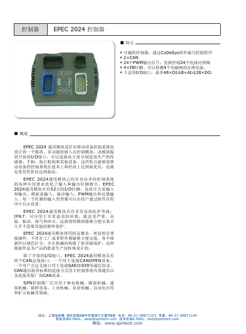
■概述EPEC 2024 通用模块是针对移动设备控制系统而设计的一个紧凑、多功能的嵌入式控制模块。
该模块提供开放的I/O接口,可以连接决大部分制造商生产的传感器、手柄、执行机构和其他设备。
这些特点能够使移动设备的控制系统在技术上和经济上达到最优化,也就是使其性价比达到最高。
EPEC 2024通用模块已经针对众多的控制系统的各种应用要求优化了输入和输出针脚数目。
EPEC 2024通用模块共有52点的I/O针脚,包括开关量输入和输出、模拟量输入、脉冲输入、PWM输出和反馈输入。
每一个针脚的输入类型都可以由用户通过软件在程序中自由设置。
EPEC 2024通用模块具有非常高的防护等级:IP67,可应用于非常恶劣的环境,能忍受严寒、高温、振动、湿气和冲击。
这就使得模块能够方便安装并几乎不需要其他的额外保护。
EPEC 2024通用模块使用的是镀金、密封的安普接插件,不管在工厂或者野外都能够方便安装。
各个接插件以颜色区分,并在机械结构做了防误插保护。
这种接插件是为产品的批量生产而特殊设计的。
除了开放的I/O接口,EPEC 2024通用模块具有两个CAN总线接口,一个用于连接CANOPEN设备,一个用户自定义接口用于连接SAEJ1939等通信协议。
CAN通信提供标准的连接方式用于控制系统内部通信以及连接其他厂商CAN设备。
SPN控制器广泛应用于林业机械、路面机械、建筑机械、破碎设备、工业机械、农业机械、自动化应用和矿山机械等领域。
■技术参数■控制器经过测试■ I/O配置I/O说明简介,详细请参考EPEC 2024用户手册内部电路原理图■ 电气特性■电气特性注释1 :超过最大值会导致输入点损坏内部电路原理图■ PWM频率控制分组■ DI/DO/PWMXM1.1 XM1.2 XM1.3 XM1.4 XM1.7 XM1.8 XM1.14 XM1.15 XM1.16 XM1.17 XM1.22 XM1.23 XM2.1 XM2.2 XM2.5 XM2.6 XM2.7 XM2.8 XM2.9 XM2.10 XM2.16 XM2.17 XM2.22 XM2.23■电气特性■电气特性■电气特性■ 电气特性地址:上海陆家嘴 浦东南路256号华夏银行大厦704室 电话:86-21-58871153 传真:86-21-58871140商务咨询E-MAIL :*****************技术咨询E-MAIL :****************网址:●2只M6螺钉(DIN912标准)●垂直或水平安装,如上图● 关于模块安装的详细信息请参考用户手册中模块的安装和接线说明。
黄石科威24V新型EC、EP说明书
AI6+、AI6-:6#通道模拟量输入端子,接热电偶、标准信号、PT100 信号。 AI7+、AI7-:7#通道模拟量输入端子,接热电偶、标准信号、PT100 信号。 AI8+、AI8-:8#通道模拟量输入端子,接热电偶、标准信号、PT100 信号。 AI9+、AI9-:9#通道模拟量输入端子,接热电偶、标准信号、PT100 信号。 CANH、CANL:CAN 网络接口端子。 A、B : RS485 网络端子 A+、B-,固化 CAN 网络配置、组建 RS485 网络。固化 CAN 网络配置时要另配 485/232 转换器。 RS0:编程口,为 232 接口,配专用通讯电缆,下载程序、与人机界面连接。 拨码开关:运行控制端子,拨动拨码开关,可编程控制器处于 RUN 或 STOP 状态。
壁挂式垂直安装
4
★ 接地方式 专用接地(最好) 共用接地(可) 公共接地(不可)
1.2 外形结构尺寸
产品型号
L(mm) 产品型号
L(mm)
EC/P-08M08R-24 100
EP-10H-24
100
EC/P-08M08T-24 100
EP-32M-24
140
EP-10E-24
100
EP-32T-24
使用注意事项
● 可编程控制器的安装位置尽量远离高电压、强电流、高频率等对周围有较强干扰的设备。 ● 请一定在可编程控制器外部组成紧急停电电路,制止正反动作同时进行的连锁电路、上下限定位连锁电路。 ● EC/EP 系列可编程控制器指令集有 86 条指令,如果程序中含有超出这 86 条指令范围的指令,可编程控制器运行时会出错。 ● 在下载梯形图或固化 CANSET 时,下载完毕后,将拨码开关拨到 RUN,等可编程控制器运行后,才能断电,否则,程序得不到固化。 ● 对于变更运行中的程序、强制输出、RUN、STOP 等操作,必须熟读使用手册,充分确认其安全之后进行。
欧姆龙PLC操作手册_c20p_c28p_c40p_c60p

OMRON Product References
1, 2, 3... 1. Indicates lists of one sort or another, such as procedures, checklists, etc.
OMRON, 1989
All rights reserved. No part of this publication may be reproduced, stored in a retrieval system, or transmitted, in any form, or by any means, mechanical, electronic, photocopying, recording, or otherwise, without the prior written permission of OMRON. No patent liability is assumed with respect to the use of the information contained herein. Moreover, because OMRON is constantly striving to improve its high–quality products, the information contained in this manual is subject to change without notice. Every precaution has been taken in the preparation of this manual. Nevertheless, OMRON assumes no responsibility for errors or omissions. Neither is any liability assumed for damages resulting from the use of the information contained in this publication.
欧真喷水织机系统集成电控使用说明书-V2.2

欧真喷水织机集成电控使用说明书(简易版)V2.2欧真自动化科技(上海)有限公司OG‐WS100喷水电控是集成化、一体化电控系统,可模块化配置电子卷取、电子送经、电子双送经,以及单喷、双喷电子储纬器。
系统核心采用高速ARM芯片,数字化管理各子系统,集成化程度高,实时控制能力强,并采用高精度编码器,精确同步和协调各系统工作,达到精准化控制。
系统电气优化布局,采用先进的电源管理技术,温升大大降低,同时使用的大量抑制电磁干扰和抗干扰措施,减小各系统间的电磁干扰,系统稳定性强。
系统采用统一的7寸彩色液晶屏,各子系统所有参数和设置都可以通过一个屏幕解决,简化了操作过程,提高了使用效率。
OG‐WS100集成化电控真正做到一体化、数字化、模块化,是一套稳定、可靠、高效的系统化产品。
一、 使用须知在使用之前,请您详细阅读本说明书,以确保正确使用本产品。
请将本说明书妥善保管,以便随时查阅。
1.在使用之前,请注意以下事项:输入电源:规格1:AC380V±15%, 50/60HZ;规格2:AC415V±15%, 50/60HZ;两种规格内部接线稍微不同。
请务必安全接地。
使用环境温度:0~45℃。
使用环境湿度:20~90%(无结露)存放环境温度:‐10~60℃。
存放环境湿度:20~90%(无结露)带慢速功能的电控,请按本说明书正确接入变频电源。
2.在使用时,请注意以下事项:通电状态,请勿打开电箱,请勿触摸电箱内部部件,以免烫伤或触电。
断电后5分钟内,请勿打开电箱,请勿触摸电箱内部部件,以免触电。
30分钟内请勿触摸带有发热标志的部件,以免烫伤。
非专业人员请勿擅自拆卸和维修电箱内部部件。
有故障无法排除或需要维修,请联系厂家。
二、 接口说明1.电箱布局(图2.1)说明:a)电子卷取伺服驱动器、电子送经1伺服驱动器和电子送经2伺服驱动器,根据需要进行配置,和当前图示可能有所不同。
b)图示为带变频慢速功能的电控,如无变频慢速功能,则接触器MSH及配套线束不安装。
电池板参数

产品编号:SD12V-5A-10A产品名称:太阳能控制器5A-10A 产品类型:太阳能控制器浏览次数:278详细介绍产品编号:SD0260 产品名称:60W单晶太阳能电池板产品类型:单晶太阳能电池板详细介绍峰值功率:60W 功差:±3%功差:±3%工作电压:17.5V工作电压:17.5V 工作电流:3.45A工作电流:3.45A 开路电压:21.6V开路电压:21.6V 短路电流:3.79A短路电流:3.79A 外形尺寸:760×670×23mm外形尺寸:760×670×23mm重量:6.0kg产品编号:SD300产品名称:太阳能逆变器产品类型:太阳能逆变器详细介绍使用范围:1.使用办公设备(如:电脑、传真机、打印机、扫描仪等);2.使用生活电器(如:游戏机、DVD、音响、摄像机、电风扇、照明灯具等);3.或需要给电池(手机、电动剃须刀、数码相机、摄像机等电池)充电时;产品特点:1.转换效率高、启动快;2.安全性能好:产品具备短路、过载、过/欠电压、超温5种保护功能;3.物理性能良好:产品采用全铝质外壳,散热性能好,表面硬氧化处理,耐摩擦性能好,并可抗一定外力的挤压或碰击;4.带负载适应性与稳定性强。
型号 SD300 SD500 SD1000额定输出功率 300w 500w 1000w最大输出功率 360w 600w 1200w峰值功率 600W 1000W 2000W输入电压 12V/24V输出电压 110VAC/220VAC输出频率 50Hz/60Hz效率(满载) >87%空载电流 <8W工作指示 LED指示工作状态输出波形纯正弦波自动保护过载,短路,过温,反接(保险),欠/过压工作环境温度 -10℃ ~ + 50℃存储温度 -30℃ ~ + 70℃方式自动控制制冷风扇总谐波失真量≤5%机器尺寸(MM) 145*155*50 235*150*70 310*150*70尺寸(MM) 195*159*70 345*190*110 420*190*110净重(KG) 1.3KG 2.2KG 3.2KG毛重(KG) 1.5KG 2.5KG 3.5KG胶体免维护蓄电池说明书一、标准:胶体免维护蓄电池符合如下标准:1、JIS C 8707-1992 阴极吸收式密封固定型铅酸蓄电池标准2、JB/T 8451-96 中华人民共和国机械行业标准3、YD/T 799-2002 中华人民共和国通信行业标准4、DL/T 637-1997 中华人民共和国电力行业标准二、应用范围:⑴电话交换机⑼办公自动化系统⑵电器设备、医疗设备及仪器仪表⑽无线电通讯系统⑶计算机不间断电源⑾应急照明⑷输变电站、开关控制和事故照明⑿便携式电器及采矿系统⑸消防、安全及报警监测⒀交通及航标信号灯⑹通信用备用电源⒁发电厂、水电站直流电源⑺变电站开关控制⒂铁路用直流电源⑻胶体、风能系统⒃移动机站三、主要特点;⑴寿命长采用耐腐蚀性好的特殊铅钙合金制成的极板,可以具有较长的浮充寿命;采用特殊胶体电液,增加电池酸量,防止电液分层,阻止极板支晶短路,确保电池使用寿命长。
华仪定位器说明书

EPPvHEP 系列电/气阀门定位器一、概述EPPvHEP 系列电/气阀门定位器 是引进国外先进技术,由本厂开发成功的产品。
本产品经“机械电子工业 自动化仪表产品质量监督检测中心”型式试验,其技术性能均达到国外同类产品水平,并经“国家级仪器 仪表防爆安全监督检验站”检验合格,获得国家级防爆合格证书。
本定位器的作用是把调节装置输出的电信号变成驱动调节阀动作的气信号,而且具有阀门定位功能,即克 服阀杆摩擦力,抵消被调价质压力变化而引起的不平衡力,从而使阀门开度对应于调节装置出的控制信号实现正确定位。
由于本定位器具有防爆结构,故能使用于爆炸危险场所。
二、特点1. 弓I 进国外先进技术,具有可靠性高、体积小、重量轻等特点。
2. 磁电组件部分采用新型动圈结构,可靠、稳定、线性好。
3. 除防爆接线盒外,在危险性区域现场可打开壳盖进行调整及检修。
4. 量程、零点调整钮采用手轮式,调整方便、并带有锁定装置。
5. 配有与各类型执行机构相配的安装板及附件,故安装容易,调整方便。
6. 防爆性能:本安型防爆等级iallCT5隔爆型防爆等级d IICT6三、型号、规格辅入维号范司L 4j -20uiADCO-KmADC 3 1 卜!5TDC4 4^]2ui ADC 12-20mADCEFP □ □ C □ □ □匚rr 阿备武嫌压阀—|不带组合如丽□td0.14—0 )6Mpa0.17^.5Mpa2 尊百分比1 正件用HEP □ □口56 本安1 普通1 单作用1裁作用1 经性2 尊百分比3 快开踊构型式 定位器作用型式 桎和方戏式 作用如式 工作晴忖例:EPP111i-Ai-As即表示该定位器为EPP系列电气阀门定位器,输入信号4-20mADG正作用、线性特性、气源压力为0.14〜0.16MPa、本安型。
四、技术规范度:小F全行程± 1%霞回小于全行程1%妊区:小于全行程0.4%4.特线件(可改变成快开、等百伶比特性〉3、气源巫力:OJ4-OA6Mpa 0.17- O.SMpa6, 最大流量:140NL伽忆(十气源压力ri:OJ4Mpa0j)7, 耗气量:5NL/min(^气源压力在O.L4MPa时)K.坏境隘度:-40匸3曲<:9、环境湿度;10~90%RHA10. 最大行稈速度:4mm/e>(rteZH B^2执行机构时)11, 输人阻抗:250境尹;4^20mADC)100Q(10^50mADC)12, 电气连&/C1/2螺绞13. 代管连擡:卡套式气管接头(0>6成①咅钢管)14、韋氐3-5ks费州援口”点羿整手轮图i EPPdlEP〉犁应位器外形阳曲2 FPP<HEP>刪电位器内部结构五、工作原理EPP<HEP定位器的工作是基于力平衡原理,如图3所示。
数字式电机保护控制器TDHD-EP说明书

0
Ext-ON 电机控制信号输入
1
外部故障输入
2
空气断路器辅助触点输入
3
空气断路器辅助触点输入
接触器线圈断线(电机运行指令但接触器辅助触点断开) 4
接触器触点粘连(电机停止指令但接触器辅助触点闭合)
5
互锁(工艺连锁)
6
常规数字输入(传输到DCS、PLC等)
7
停止功能,当AC220V消失时停止
1
8
停止功能,当AC220V有效时停止
3
0:不使用, 1-20/1r-C使用
7
0:不使用, 5-90/5[%]使用
0
0:直接动作, 1-60/1秒:延时时间
5
EPZ:0:接地功能不使用 0.05-0.6/0.01[A]
0:不使用, 0.05-0.6A/0.01A
G-C 接地保护
0
EPN:0:接地功能不使用 0.5-6.0/0.1[A]
0:不使用, 0.5-6A/0.1A
就地选择输入 火线 零线
可编程输出点 1 电机控制信号输入
可编程输出点 2 可编程输出点 3 报警输出或自动控制方式输出公共端(无源节点)
秦皇岛市天大海德自动化工程有限公司
5
▶▶参数设置
项 目
名称
t-C 动作曲线
r-C 额定电流 Ctr 外部CT比 tUn MCT穿绕次数 Sdt 启动延时
十六进制数值
C
0
0
4
Po3 输出点
30.o3 控制位
设定范围0000-FFFF (十六进制),出厂值3DF5 15 14 13 12 11 10 9 8 7 6 5 4 3 2 1 0
0空
累
电子比例(EP)控制器说明书
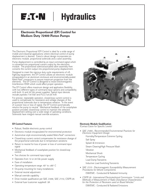
The Electronic Proportional (EP) Control is ideal for a wide range of mobile and industrial applications where electrical control of pump displacement is desired. Eaton’s robust design incorporates an electronic module, proportional solenoids and a valve assembly. Pump displacement is controlled by an input command signal which is converted into proportional current output by the electronic module. The proportional solenoid-actuated valve assembly then converts the current output into proportional pump displacement. Designed to meet the rigorous duty cycle requirements of off-highway equipment, the EP Control utilizes an electronic module encapsulated in an aluminum enclosure and environmentally-sealed Metri-Pack®connectors to assure maximum protection from the elements. The EP Control is designed to resist Electromagnetic Interference (EMI) which could affect proper operation.The EP Control offers maximum design and application flexibility with two different types of command input options and compatibility with both 12 and 24 Vdc power supplies. Typical input devices include joysticks (1-6 Vdc) and PLCs (±4-20 mA).For precise, repeatable operation, closed-loop current control is used to compensate for resistance and voltage changes of the proportional solenoids due to temperature variation. In the eventof a power loss or loss of signal, the EP Control automatically returns the pump to neutral. Mechanical feedback of the swashplate position provides closed-loop control to maintain the selected displacement setting over a wide range of operating conditions. Solenoids have integral manual override actuators.EP Control Features•Robust, flexible electronic pump control•Electronic module encapsulated for environmental protection •Automotive style environmentally sealed Metri-Pack®connectors •Closed-loop current control compensates for resistance change of the proportional solenoids due to temperature variations •Return to neutral for loss of power or loss of command input signal• Mechanical feedback of swashplate position for closed-loop control•Two choices for command input signal• Operates from 12 or 24 Vdc power supply•Ease of installation•Operating temperature range -40°to +85°C•On-pump mounting for many installations•External neutral adjustment• Manual override capability• Drive module qualification per SAE J1455, SAE J1113, CISPR 25•External fuse (customer supplied): 3A Electronic Module Qualification(Contact Eaton for Specific Levels)•SAE J1455 - Recommended Environmental Practices for Electronic Equipment DesignHumidity/Temperature Extreme CyclingSalt SpraySplash & ImmersionSteam Cleaning/High Pressure WashVibrationMechanical ShockTemperature CyclingLoad Dump TransientsInductive Load Switching Transients•SAE J1113 - Electromagnetic Susceptibility Measurement Procedures for Vehicle ComponentsEMI/EMC - Conducted & Radiated Immunity•CISPR 25 - International Electrotechnical Commission “Limits and Methods of Measurement of Radio Disturbance Characteristics for the Protection of Receivers used on Board Vehicles”EMI/EMC - Conducted & Radiated Emissions2EATON EP Control for Medium Duty 72400 Piston Pumps Data Sheet E-PUPI-MS002-E September 2002Electronic Proportional (EP) Control For Medium Duty 72400 Piston PumpsInterconnect SchematicPOWER SUPPLY CONNECTOR (2-Pin)Solenoid ConnectorSolenoid 2PNOMINAL COMMAND MODEL CODE DESCRIPTIONINPUT IMPEDANCE OF MODEL CODECOMMAND INPUT SIGNALTYPICAL INPUT DEVICESELECTRONIC MODULEJoysticks or potentiometers with a resistance EE 1 to 6 Vdc Potentiometric between 160 ohms and 50K ohms 500K Ohms EG ±4-20 mA Current Loop Programmable Logic Controllers (PLC)250 OhmsEC 12 Volts Requires customer supplied electronics ED 24 VoltsRequires customer supplied electronicsModel Code Position 16,173EATON EP Control for Medium Duty 72400 Piston Pumps Data Sheet E-PUPI-MS002-E September 2002InstallationValve AssemblyElectronic Module Mating Connector KitKIT NO.PART (QTY .)DELPHI PACKARD P/N990762-000Command Input Signal Connector (1) 1211 0293 Terminal (3)1204 8074Cable Seal (3)1204 8086Cavity Plug (1)1205 9168Secondary Lock (1) 1205 2845Power Supply Connector (1) 1205 2641Terminal (2) 1204 8074Cable Seal (2) 1204 8086Secondary Lock (1) 1205 2634Recommended wire size: 16 - 18 AWGRecommended cable diameter: 2.03 - 2.80 mmAlternate reference source: Pioneer Standard Electronics 1-800-257-6613Solenoid Coil Mating Connector Kit(not needed when using an Eaton Electronic Module)KIT NO.PART (QTY .)DELPHI PACKARD P/N9900023-000Connector (1)1218 6568 Terminal (4) 1204 8074Cable Seal (4) 1204 8086Secondary Lock (1) 1204 7948Recommended wire size: 16 - 18 AWGRecommended cable diameter: 2.03 - 2.80 mmAlternate reference source: Pioneer Standard Electronics Solenoid Connector Update KitNote:This kit was created to update electrical connectors, on field units, to the current design. It is to be used when replacing solenoid coils, with the previous-design connectors, with new coils with new-style connectors.The kit contains necessary parts and a tool to update the connector that mates the new solenoid coil connector.KIT NO.PART (QTY .)DELPHI PACKARD P/N9900045-000Tool (1) 1209 44294-Pin Housing Connector (Female) (1) 1218 65684-Pin Housing Connector (Male) (1) 1218 6271EP Control Connector Kits© 2001 Eaton Corporation All Rights Reserved Printed in USADocument No. E-PUPI-MS002-E Supersedes 01-10-0003-EN-0901September 2002Pump Displacement vs. Input SignalEP Control KitsTypical Control CharacteristicsEaton14615 Lone Oak Road Eden Prairie, MN 55344Telephone: 952 937-9800Fax: 952 974-7130Eaton20 Rosamond Road Footscray Victory 3011AustraliaTele: (61) 3 9319 8222Fax: (61) 3 9318 5714Eaton46 New Lane, Havant Hampshire PO9 2NB EnglandTele: (44) 23 92 486 451Fax: (44) 23 92 487 110。
EP、EC系列PLC脉冲输出说明书
前言感谢您使用黄石市科威自控有限公司的EC/EP系列PLC的高速脉冲输出单元。
在使用EC/EP系列PLC的高速脉冲输出之前,请务必仔细阅读该手册,以便正确使用。
本手册为随机发送的附件,请妥善保管。
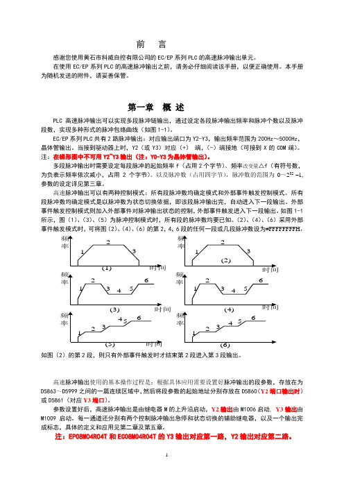
第一章概述PLC高速脉冲输出可以实现多段脉冲链输出,通过设定各段脉冲输出频率和脉冲个数以及脉冲段数,实现多种形式的脉冲包络曲线(如图1-1)。
EC/EP系列PLC共有2路脉冲输出:对应输出端口为Y2-Y3,输出频率范围为200Hz~5000Hz,晶体管输出。
当接到驱动器上时,Y2(或Y3)对应(+)端,(-)端接地(可接到X的COM端)。
注:在梯形图中不可用Y2~Y3输出(注:Y0-Y3为晶体管输出)。
多段脉冲输出时需要设定每段脉冲的起始频率f(占用2个字节)、频率改变量△f(有符号数,为负表示频率依次减小,占用2个字节)、以及脉冲数(占用四字节),脉冲数的范围为0~232 –1,参数的设定详见第三章。
高速脉冲输出可以有两种控制模式:所有段脉冲数均确定模式和外部事件触发控制模式。
所有段脉冲数均确定模式是以脉冲数为状态切换依据,即该段脉冲输出完,自动进入下一段输出。
外部事件触发控制模式则加入外部事件对脉冲输出状态的控制,外部事件触发进入下一段输出。
如图1-1所示,图(1)、(3)、(5)为脉冲控制模式时,所有段的脉冲数均要已知。
(2)、(4)、(6)采用外部事件触发模式时,可将图(2)、(4)、(6)的第2,4,6段的任何一段或几段脉冲数设为#FFFFFFFFH,如图(2)的第2段,则只有外部事件触发时才结束第2段进入第3段输出。
高速脉冲输出使用的基本操作过程是:根据具体应用需要设置好脉冲输出的段参数,存放在为D5863~D5999之间的一篇连续区域中,然后将段参数的起始地址分别存放在D5860(Y2端口输出时)或D5861(对应Y3端口)。
参数设置好后,高速脉冲输出是由继电器M的上升沿启动,Y2输出由M1006启动, Y3输出由M1009启动。
Pcon PCON-C CG CF 控制器 定位型 说明书 第五版

[设置、运行、维护]
● 使用产品时,请根据需要使用防护手套、防护眼镜及安全靴等,以确保安全。
[废弃]
● 产品无法使用或不需要时,请作为工业废弃物作适当废弃处理。
其 他
■ 如未能遵守全部“安全注意事项” ,本公司将不承担任何责任。
目录
1. 概要 ................................................................................................................... 1
4. 最新数据的保存提示
本产品采用非挥发性存储器作为位置表和参数的存储媒体。通常情况下切断电源时将会保持数据, 但当非挥发性存储器发生故障时,数据将会丢失。 另外,因其他原因需要更换控制器时,为尽快恢复数据,强烈推荐保存位置表和参数的最新数据。 保存方法如下 : ① 使用联机软件,存储到光盘或软盘中。 ② 制作位置表或参数表,以书面形式保留。
● ● ●
产品出现异常发热、冒烟或异味时,请立即切断电源。继续使用可能导致产品破损或引起火灾。 产品的保护装置(报警)启动时,请立即切断电源。否则可能因产品异常运转导致受伤或产品的 破损及损伤。切断电源后,请查明并排除报警原因,然后重新接通电源。 如果接通电源后产品的 LED 不亮,请立即切断电源。运行端的保护装置(保险丝等)可能未切 断并继续工作。故障修理请委托购买本产品的本公司销售单位。
1
2
3 4
5
CAUTION
②伺服 ON 输入信号(SON)有效 / 无效的选择 本控制器设有伺服 ON 输入信号,以便在 PLC 侧可以对伺服 ON/OFF 进行控制,因此需要选择 该信号有效或无效。 选择方法为在参数 No.21(伺服 ON 输入无效选择)中设定数字 0 或 1。 有效(使用) 无效(不使用) 出厂时设定为 0[有效] 。 ③暂停信号(*STP)有效 / 无效的选择 根据失效保护设计,暂停信号采用常闭接点。 因此,通常情况下需要事先将其调整为 ON 状态。 但考虑到部分不使用该信号的用途,可通过参数进行选择,无需特意将其设定为 ON 状态。 选择方法为在参数 No.15(暂停输入无效选择)中设定数字 0 或 1。 有效(使用) 无效(不使用) 出厂时设定为 0[有效] 0 1 0 1
海埃尔气动多位选电气驱动型温度控制器选择器手册说明书
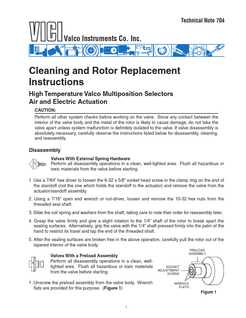
1Cleaning and Rotor ReplacementInstructionsHigh Temperature Valco Multiposition SelectorsAir and Electric ActuationCAUTION:Perform all other system checks before working on the valve. Since any contact between the interior of the valve body and the metal of the rotor is likely to cause damage, do not take the valve apart unless system malfunction is definitely isolated to the valve. If valve disassembly is absolutely necessary, carefully observe the instructions listed below for disassembly, cleaning, and reassembly.DisassemblyValves With External Spring HardwarePerform all disassembly operations in a clean, well-lighted area. Flush all hazardous or toxic materials from the valve before starting.1. Use a 7/64” hex driver to loosen the 6-32 x 5/8” socket head screw in the clamp ring on the end of the standoff (not the one which holds the standoff to the actuator) and remove the valve from the actuator/standoff assembly.2. Using a 7/16” open end wrench or nut-driver, loosen and remove the 10-32 hex nuts from the threaded seal shaft.3. Slide the coil spring and washers from the shaft, taking care to note their order for reassembly later.4. Grasp the valve firmly and give a slight rotation to the 1/4” shaft of the rotor to break apart the sealing surfaces. Alternatively, grip the valve with the 1/4” shaft pressed firmly into the palm of the hand to restrict its travel and tap the end of the threaded shaft.5. After the sealing surfaces are broken free in the above operation, carefully pull the rotor out of the tapered interior of the valve body.Valves With a Preload AssemblyPerform all disassembly operations in a clean, well-lighted area. Flush all hazardous or toxic materialsfrom the valve before starting.1. Unscrew the preload assembly from the valve body. Wrenchflats are provided for this purpose. (Figure 1)PRELOAD ASSEMBLY WRENCH FLATSSOCKET ADJUSTMENT SCREWFigure 1Technical Note 704Valco Instruments Co. Inc.22. Engage the end of the rotor (Figure 2) with a pencil-type magnet, availablefrom Valco or any electronic components supplier.3. Step the actuator through several positions to break apart the sealing surfacesand carefully withdraw the rotor from the valve body with the magnet.4. Use a 7/64" hex driver to loosen the 6-32 x 5/8" socket head screw in theclamp on the end of the standoff (not the one that holds the standoff to theactuator) and remove the valve body from the actuator/standoff assembly.Cleaning1. Using clean dry air, blow any loose debris from the valve body and the rotor.2. Using a strong solvent and an optical quality lint-free wiper such as a Kimwipe, wipe away anyloosely bound seal material which may have worn free and adhered to either surface. Avoid using halocarbon solvents if the valve is to be used in a system with electron capture detection, since some of the solvents may persist at the trace level. Consult the Manufacturer’s Data Safety sheet for whatever solvent is utilized.NOTE: If the valve has been used with aqueous buffer solutions and some leakage has occurred,wipe the sealing surfaces of the valve with a water-moistened Kimwipe before using a nonpolar solvent to clean any seal material still adhering to the valve’s interior.3. Visually inspect the interior of the valve body. The conical surface should appear uniform as well ashighly polished. If scratches are visible between the ports or anywhere which suggests a potential leakage path or wear source, the valve should be returned to the factory for regrinding. If the rotor’s sealing surface shows any scratches and/or a narrowing of the surface flow passages, replacement is necessary. If the valve body interior is in good condition, a field replacement of the rotor may be effected using the following procedure.Assembly and Alignment Procedure (New or Existing Rotor)The valve will have either one (SD and SC types) or two (SF and ST types) rows of ports evenly spaced around the circumference of the body. See Figure 3. In addition there will be one (SD and SF types) or two (SC and ST types) “common” ports offset to either side of these rows. The rotor will have either one or two flow appearing as engraved rings around the seal, which intersect the common port(s). Flow passages perpendicular to the ring(s) connecting the ring(s) to the selected port(s).STUWThe only configuration which does not fall within this description is the STUW. Unlike thestandard ST, these have one row of ports around the circumference, with two commonports offset in the same direction. The common ports are 180° apart, so only one showsin Figure 3. Special instructions and descriptions regarding STUW and/or SDUW valveswill be highlighted in this manner at several points in the procedures below.The alignment procedure is a way of centering the perpendicular engraving on the selected port by determining the point at which flow begins (when the engraving is just beginning to intersect the port)and the point at which flow ends (when the engraving has ceased to intersect the port), and centering the rotor between those two points.1. Make sure that all sealing surfaces are clean and dry.2. If a used rotor is to be reinstalled, clean it with a light solvent and blow the passages clean withcompressed air. Discard the rotor if any scratches are visible between ports.Figure 2:Valve viewed from preload endAsembly and Alignment Procedure(continued)3. Locate the common port offset toward the small end of the valve interior. (In SD and SC valves thisis the only common port.) This port, called the alignment inlet in Figure 3, will be the designated inlet throughout this procedure.STUWEither common port can serve as the alignment inlet.4. Put a nut in the port corresponding to the last or highest numbered position.For an electric actuator: With the valve oriented as in Figure 3, the nut goes in the first port above the alignment inlet.For an air actuator: With the valve oriented as in Figure 3, the nut goes in the first port below the alignment inlet.5. Locate the flow passage(s) perpendicular to the ring(s) that go around the seal. Note the pin whichpasses through the shaft. The end of the pin on the same side of the rotor as the flow passages(s) perpendicular to the ring(s) will be used as a pointer. (Figure 3)SDConfigurationSCConfigurationSFConfigurationENGRAVED RINGPERPENDICULARENGRAVINGSTFConfigurationSTUWConfigurationSTConfigurationENGRAVED RINGPERPENDICULARENGRAVINGPERPENDICULARENGRAVINGENGRAVED RING PERPENDICULARENGRAVINGENGRAVED RINGPERPENDICULARENGRAVINGENGRAVED RING PERPENDICULARENGRAVINGENGRAVED RINGALIGNMENT INLETALIGNMENT INLETALIGNMENT INLETALIGNMENT INLET ALIGNMENT INLET ALIGNMENT INLETFigure 3:Typical multiposition valve bodies and seals (external spring hardware rotor shown above preload rotor)Figure 436. Insert the rotor in the valve body with the pointer centered on the nut, being careful not to touch thepolished interior surface of the valve body with any of the metal parts of the rotor.7.If the valve has external spring hardware, slide the three washers (in this sequence: 3/4" ODwasher, polyimide washer, standard 1/2" OD stainless steel washer) over the 3/16" diameter threaded shaft while holding the rotor pressed firmly into the valve body. The flat side of the 3/4" back washer should rest on the rear collar of the valve. Next put the spring and the first stainless hex nut in place.Tighten the nut 1/2 turn beyond the point where the spring touches the hardware at both ends, and lock the second nut against it.STUW, SDUW, MWScrew the preload in fingertight.8. For an electric actuator: Plug the actuator in. If the position indicator doesn’t read “1”, flip theswitch to the HOME position.For an air actuator: Determine that the actuator is in Position 1. If necessary override or disable the means of pulsing the air to the actuator so that pressure is continuously applied to the actuator port nearest the valve.9. Place the valve on the actuator/standoff. By convention, the factory alignment places the commonport(s) at 12 o’clock. Re-orienting the standoff drive shaft on the square drive of the actuator allows three other possibilities.Make sure that the pin in the rotor is engaged by the slots of the standoff drive shaft, and tighten the standoff clamp screw. Loosen the screw in the clamp ring which holds the standoff to the actuator enough to allow the valve/standoff assembly to be turned during the alignment procedure.10. Establish a flow of clean gas (50 psi is adequate) into the alignment inlet.STUWEstablish gas flow into the common port at 6 o’clock (alignment inlet in Figure 3).NOTE: When listening for flow in the following steps, it is helpful if the fittings are removed from the port under consideration but left in the adjacent ports. If all the fittings have been removed, install a loop connecting the two ports adjacent to the target port to better isolate the sound of the flow.CAUTION:Up to this point the instructions have applied to both air and electrically actuated valves. Because the two types of actuators rotate in opposite directions, it is necessary for the instructions to diverge at this point. For an electrically actuated valve, proceed with the steps immediately following. For an air actuated valve, look for the heading on the next page.For Electrically Actuated Valves11.With the valve facing you and the actuator behind the valve, the port to the left of or counterclock-wise from the alignment inlet corresponds to Position 1.STUWWith the common port at 6 o’clock as the inlet, the port to the left of or counterclockwisefrom the common port at 12 o’clock corresponds to Position 1.If the assembly was done properly in Step 5, air will be coming out of the port to the right of the alignment inlet (or common port at 12 o’clock for STUW’s). If so, proceed to Step 12. If the initial alignment was off a little, grip the valve and rotate it slightly in either direction (the actuator keeps the rotor fixed) until gas flows from this port. This sets up the “staging area” for the approach to Position 1.4512.Slowly rotate the valve clockwise until the first traceof flow is heard from the port of Position 1.13.While holding the valve steady, use a soft pencil orink marker to make a mark on the standoff corre-sponding to the slot in the actuator clamp ring. Thisslot makes a clear fixed reference point for observingrelative rotational positions. (Figure 5)14.Continue the slow manual clockwise rotation of thevalve body through the point of peak flow and onuntil the flow stops or is barely perceptible, as inStep 12.15.Make another mark as in Step 13. (Figure 5)16.Make a third pencil mark centered between the first two and rotate the valve counterclockwiseuntil this midway mark is reached. (Figure 5)17.While holding the valve steady, firmly tighten the screw in the clamp ring. The rotor should beproperly positioned at the point of maximum flow when the actuator is stepped to the next position.It is a good idea to cycle the valve through all its positions to be certain everything is functioning properly. In some cases it is possible to do an additional alignment check by simply looking down the fitting detail and into the port as the valve is stepped from position to position. If it is a valve which has a relatively short distance from the bottom of the detail to the internal taper, the engraved “dimples”on the seal are visible as they come into alignment with the port.For Air Actuated Valves11.With the valve facing you and the actuator behind the valve, the port to the right of or clockwise from the alignment inlet corresponds to Position 1.STUWWith the common port at 6 o’clock as the inlet, the port to the right of or clockwise fromthe common port at 12 o’clock corresponds to Position 1.If the assembly was done properly in Assembly Step 5, air will be coming out of the port to the left of the alignment inlet (or common port at 12 o’clock for STUW’s). If so, proceed to Step 12. If it is not,grip the valve and rotate it counterclockwise until gas flows from this port. Depending on which way the initial alignment was off, this will take either a veryslight rotation or nearly a full revolution. (Even though flowmight have been achieved by a slight clockwise rotation, the air actuator will not keep the rotor fixed against a force in thatdirection.) This sets up the “staging area” for the approach to Position 1.12.Grip the valve and slowly rotate it counterclockwiseuntil the first traces of flow are heard from the port ofPosition 1.13.While holding the valve steady, use a soft pencil or inkmarker to make a mark on the standoff correspond-ing to the slot in the actuator clamp ring. This slotmakes a clear fixed reference point for observing rela-tive rotational positions. (Figure 6)CLAMP RING SCREW Figure 5: Marking valve or standoff during alignment procedureSECOND MARK CLAMP RING SCREW Figure 6: Marking valve or standoff during alignment procedure®®North America, South America, and Australia/Oceania contact:Europe, Asia, and Africa contact:Valco Instruments Co. Inc.VICI AG International Cheminert ® and VICI ® are registered trademarks of Valco Instruments Co. Inc. and VICI AG P .O. Box 55603Houston, TX 77255Sales:(800) 367-8424Tech:(713) 688-9345Fax:(713)**********************Parkstrasse 2CH-6214 Schenkon Switzerland Phone:+41 41 925 6200Fax:+***********************14. Continue the slow manual counterclockwise rotation of the valve body through the point of peakflow and on until the flow stops or is barely perceptible, as in Step 12.15. Make another mark as in Step 13. (Figure 6)16. Make a third pencil mark centered between the first two and rotate the valve clockwise until thismidway mark is reached. (Figure 6)17. While holding the valve steady, firmly tighten the screw in the clamp ring. The rotor should beproperly p os-itioned at the point of maximum flow when the actuator is stepped to the next position. It is a good idea to cycle the valve through all its p ositions to be certain everything is functioning properly. In some cases it is possible to do an additional alignment check by simply looking down the fitting detail and into the port as the valve is stepped from position to position. If it is a valve which has a relatively short distance from the bottom of the detail to the internal taper, the engraved “dimples” on the seal are visible as they come into alignment with the port.Conditioning Procedure Caution:This information applies only to valves with Valcon “T” rotors. Do not perform the conditioning procedure unless you are certain that the valve has a “T’ rotor.The assembly instructions above put a minimum amount of tension on the spring to facilitate the manual adjustments required in the alignment procedure. Before proceeding with this section, tighten the nuts on the spring an additional 1/2 turn. If the valve is a preload type, tighten the preload assembly until the threads bottom out.With carrier gas (oxygen-free) flowing through all the ports, rapidly heat the valve to 330°C. After this temperature is reached, actuate the valve through 2 or 3 complete revolutions. The valve may be slightly sticky or hard to turn on the first cycle, but should be free on subsequent actuations. The valve may then be cooled back to ambient temperature or to the actual usage temperature.Leak Detection1. The valve should be tested with a gas leak detector. If a leak detector is unavailable, an alternative is to pressurize the valve with an appropriate gas and immerse it in a solvent with low surface tension, e.g. 2-propanol. Be careful to test for gross leaks before immersing the valve.Wear eye protection .2. If the valve leaks, tighten the nuts in 1/4 turn increments, cycling the valve through a complete revo-lution between each 1/4 turn of tension, until the leaking stops. T est after each additional 1/4 turn. Never tighten the spring to the point where its windings touch one another.STUW, SDUW, MWIf the valve leaks, it must be returned to the factory for repair.Consult the factory if additional help is needed. TN-704 Rev 4/17。
分体式太阳能充放电控制器
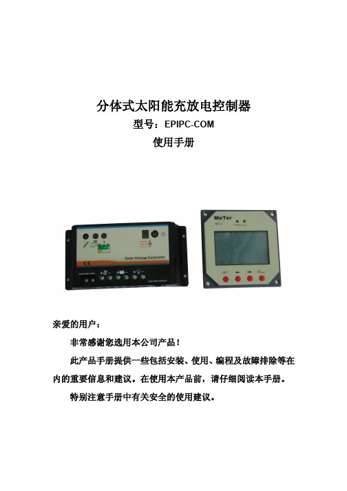
分体式太阳能充放电控制器型号:EPIPC-COM使用手册亲爱的用户:非常感谢您选用本公司产品!此产品手册提供一些包括安装、使用、编程及故障排除等在内的重要信息和建议。
在使用本产品前,请仔细阅读本手册。
特别注意手册中有关安全的使用建议。
一、产品特点:新一代的分体式太阳能充放电控制器,是一款根据最新的技术标准开发的,代表业界最新水平的产品。
此产品拥有许多卓越的特性。
如:●指示清晰明了的多功能LCD液晶显示器,以数字和图形形式显示充电状态及系统参数。
●先进的可编程功能。
●PWM和开关串联充电方式可选。
●蓄电池类型选择等。
●电池容量可以设置。
●全面的电子保护措施,过载、短路保护、防反接等电子保护。
●自识别电压(12V/24V)。
●具有温度补偿功能,并可以调节参数。
●四个按键选择调整参数。
二、主要功能:●控制器主要用来保护蓄电池,避免源自太阳能电池板的能量的过度充电及负载运行造成的过度放电。
●充电特性包括几个阶段,控制器可以根据环境温度自动调节充电电压(自动温度补偿)。
●控制器自动识别12V或24V系统额定电压。
●控制器通过自身或者显示器上的按键,允许使用者手动开启和关闭负载端的输出,从而实现手动控制负载开关的目的。
●通过显示器上的按键可以设置充电方式、蓄电池标称安时数、温度补偿系数、蓄电池类型。
●本产品拥有一系列的显示和保护功能。
三、使用建议:●本控制器主机在运行期间本身会发热,必须安装在有适当的通风散热的环境中。
避免安装在狭小的隔热的空间内。
●本控制器本身不需要任何维护,如需清洁请使用干布擦拭。
●蓄电池需要经常性的充满(至少一个月一次),才能有效的保证使用使用寿命,否则蓄电池很容易永久损坏。
●在系统运行期间,只有充入的能量大于放出的能量,蓄电池才会被充满,在计算系统配置时请注意这一点,特别是在另外增加负载时。
四、安装和接线:安装注意事项控制器最好在户内使用。
避免阳光直射,放置于干燥环境里。
一定不要安装在潮湿的房间里(例如浴室)。
CNG电控EPR系统零部件说明和安装手册
排气氧传感器用于提供燃料供给时的闭环反馈,并在燃料供给速度达不到理想 值时,对该速度进行修正。 1.2 电控调压器(EPR)
HD EPR(重型电控调压器)通过调节混合器的供气压力来控制发动机的燃料 供给速度。 1.3 混合器
该系统非常适合于未来的排放法规且容易配置。正因为这样,该系统可用于排 量范围为5-15L的重型火花点火发动机,自然吸气或是涡轮增压均可。最重要的是, 电控EPR燃气系统为燃气发动机提供了出众的驱动性能和燃料经济性。不论是采用 当量比燃烧还是稀薄燃烧的燃料控制策略,燃料的供给、点火、负荷限制和速度管 理都可以进行任意组合。
本文对系统和部件作了简要的功能描述,列出了一些控制策略特性和诊断方 法,并详述了系统基本部件的安装和应用要求。
3
第二章 系统概述
该部分简要描述了系统的一般功能,并列出了一些控制策略特性和诊断方法。
1.0 系统和部件的功能
下面讨论的是系统运行的一般原理以及各部件的主要用途。第三章则是针对各 产品更详细的描述。
HD GCP可按应用要求配置发动机风扇的开/关控制。 2.2 对加注燃料进行湿度补偿
HD GCP具有通过ECI专有Envirotech传感器进行湿度补偿的特性。具体的湿度 信息用于修正燃料和增压水平,从而在湿度大的情况下能保持功率,防止燃烧不良。 燃料的经济效益也可通过使发动机运行时减小不良燃烧来得到实现。 2.3 PTO(动力输出)和远程 PTO
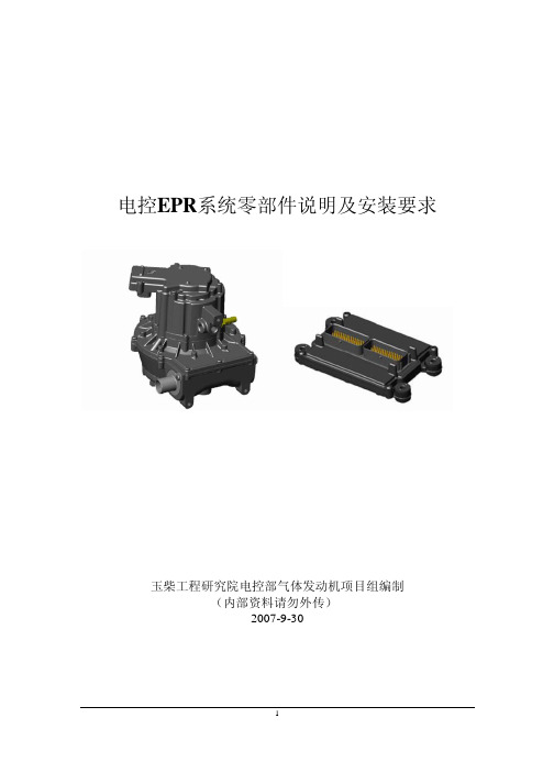
电控EPR系统零部件说明及安装要求
玉柴工程研究院电控部气体发动机项目组编制 (内部资料请勿外传) 2007-9-30
1
目录
第一章 引言 ........................................................................................................................... 3 第二章 系统概述 ................................................................................................................... 4
PLC系列电控设备操作使用说明书(高压)
高压部分
编制
审查
批准
2008年10月
交流矿井提升机TK-PLC系列
电控系统使用说明书
代号
SPLC—G01
共12页
第1页
1、电控设备技术特性及适用环境
1.1电控设备技术特性
1.2电控设备使用环境
2、电控系统的主要组成部分与作用
2.1PLC简介
2.2主回路
2.3安全回路
2.4测速回路
2.5控制回路
SPLC-G01
共12页
第4页
2.2主回路
①定子回路
6KV高压电源经高压电源柜接入电动机定子绕组,具有短路、过负荷和欠电压保护等功能。
②转子回路
电动机转子绕组外接八级电阻。在提升机运行过程中,按电流为主、时间为辅的原则分段切除电机转子外接电阻来改变电动机的起动和制动特性,以满足电动机减/加速控制的要求。
交流矿井提升机TK-PLC系列
电控系统使用说明书
代号
SPLC-G01
共12页
第10页
b)断开高压电源,转子接入全部电阻。经过消弧延时后动力制动自动投入并切除第一级电阻,提升机逐渐减速。
交流矿井提升机TK-PLC系列电控系统使用说明书
代号
SPLC-G01
共12页
第5页
(5)制动油压过高保护
液压站制动油压超过要求时,远传压力表输出模拟量(0-5V)电压升高,输入智能控制仪表输入端的模拟信号变大,智能控制仪表经比较判断后输出开关报警信号,断开安全回路,安全回路信号灯灭,实现安全保护,同时操作台显示盘上信号灯亮。
(2)安装在主机上的光电编码器可实现对提升机运行速度和位置的后备保护及实时深度指示。
2.5.控制回路
黄石市科威自控 EC EP 系列可编程控制器 说明书

̵
)§ȩ ᕺ %Å ˤ / (& (3 " ÅP
ȩ (& (3 " ÅP )̵ )ͫؿ))µ˸ ɑ࡙ ȩ ˏ J Ƴ $ µ˸( - Ǟ " ŝ ´ )O: ౧ ɑ
α ǎࣣ ࢨ Ȓ $- ÖǛ /
s Č ȏ ૭ ȏ 9/ Č α
ؿ J პ* 0 - ቱඥȒ $ / / )
ၒᇗˣ ঠ ǎ ڣ̕ ܝ$- ቱඥȒ α
- ڣ̕ µ ඥ Ѥ α
ǎࣣ ࢨ Ȓ $- Ƒķ ң dž - ě*ލң ቱඥs Ӊ ඥӉ ˣ " ÅP ˷. ćੜcě*ލ α s G ࢠছ̤ ލ α
ѤƑ/ 1 Ѥ Ǟऋ 9 ঠ ćੜc ލ α s ቱඥȒ ҈ ) 3 Ѥ α
- ̵ )˹ ၒඥ ࡙ $ % ލ α
࡙ - ͫؿ Ã - Ŝ ě*ލ α
" ÅP s ȉූһ/- 2 _ ऋ 2 ħķ ᇍ ֦ܴ ၠ ) t " ÅP .ඪ ɶ + Pࡘ࡙ WȒ - - + tȉ- +
(& (3 " ÅP 8 ַƑ ᄇ - & " ÅP -
ᇇ &$16(7 ᇇ҈ ˫ ̤581 " ÅP - ܝ$ ַ ̤
ǎ - Ƒ ַ Pᇗ 581 6723ķ Ȓ ؿ )ȩ µ˸ ˏ ၒJ s I) -
ݗׁ " ÅP )
v Č ΰP v $ Č ׁ ȏ / ȏ
9
జ 3 c )
3
ළ" 56
0 ǒ- v 0
ESPIC PH(H)中文基本操作篇(广爱)
6
1.3 关于试样的保护
危险
为了防止试验箱内出现异常高温,损伤试样,本试验箱装有如下保护装置。 请充分理解试验箱的各种功能,并正确使用。
保护器 超温自动保护功能 (内装控制器)
1. 乙醚、汽油、乙醛、环氧丙烷、二硫化碳及其它着火点不到-30℃的物品 2. 正乙烷、环氧乙烷、丙酮、苯、丁酮及其它着火点在-30℃~0℃之内的物品 3. 甲醇、乙醇、二甲苯、酸醋戊酯以及着火点在 0~30℃之内的物品 4. 煤油、柴油、松节油、异戊醇、醋酸以及着火点在 30~65℃之内的物品
可燃性气体
但是由于rl9会有残留的图像显示所以请按电源键以外的键来消除显38表71报警一览表显示项目故障内容推断原因处理rl00烧坏温度检测端的异常温度传感器的接线不良正确连接传感器试样的热值大减少试样的热值换气量太大打开调节风门rl01温度自动升高过温度指示即设定值高出10以上设定温度低设定在室温20以上上限温度警报的设定值低更改上限温度警报的设定值rl02上限温度报警箱内温度变得比上限温度警报的设定值高试样的热值大减少试样的热值下限温度警报的设定值高更改下限温度警报的设定值rl03下限温度报警箱内温度变得比下限温度警报的设定值低换气量太多关上调节风门超温保护器的设提高超温保护器的设定值超温保护器超温保护器动试样的热值大减少试样的热值rl06温度熔断器温度熔断器熔断了加热系统的异常业务呼叫鼓风机温度开关除401以外鼓风机温度开关动作rl07鼓风机过载继电器除401以外鼓风机过载继电器断开鼓风机的旋转轴停止转动业务呼叫e1存储器的故障内部存储器异内部存储器异常业务呼叫e2存储器的故障外部存储器异外部存储器异常业务呼叫cpu的异常cpu失控由噪音引起的故改善电源环境3972其他故障下面将对以下事项进行说明
Eaton EPCT Fire Touchscreen 基于电子火灾泵控制器产品说明说明书
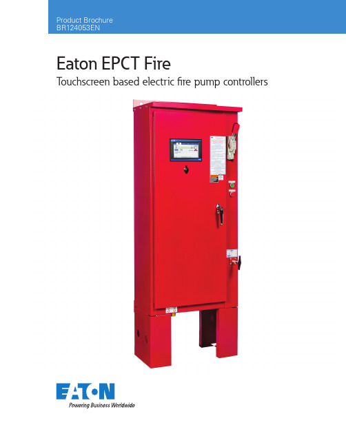
Eaton EPCT FireT ouchscreen based electric fi re pump controllersProduct DescriptionThe EPCT Fire features an advanced, 7” color touchscreen that incorporates both the fire pump controller (FPC) and automatic transfer switch (ATS) functionality into one, intuitive display. Designed solely with the consumer in mind, the EPCT Fireenables technicians to commission the fire pump controller faster; troubleshooting is made easier and is more effective through the use on-screen history filtering and diagnostic monitoring.All full-service fire pump controllers can be offered in either full-voltage or reduced voltages starting methods:• FD/FT20 - Limited service• FD/FT30 - Across-the-line• FD/FT40 - Part winding• FD/FT50 - Primary resistor• FD/FT60 - Autotransformer• FD/FT70 - WYE-Delta (Star-Delta) open transition• FD/FT80 - WYE-Delta (Star-Delta) closed transition• FD/FT90 - Soft startProduct FeaturesT ouchscreen DisplayGeneralSpeed of commissioning, configuration and troubleshooting are more critical to businesses today more than ever. Through theuse of a 7” touchscreen, users can easily program all site specific setpoints through an intuitive menu structure, view all critical system information, and troubleshoot quickly and accurately via on-screen diagnostics.Automatic Transfer Switch IntegrationGoing away from the multiple screen approach, the EPCT Fire touchscreen integrates both the Fire Pump Controller and Automatic Transfer Switch into one display enabling the user to effectively manage programming and operation from one source. Commissioning SimplifiedThe Startup tab features all controller related commissioning tasks such as: Quick Setup, Setup Phase Reversal, Flow Test, Manual/ Automatic Starts, and Test Alarms.UL Type RatingThe touchscreen display has been tested in accordance with UL and achieves a type 4X rating.Programming MenuStartup tabThis tab system enables the user to complete all controller related commissioning tasks. Each sub-menu within the Startup tab guides the user through step-by-step, intuitive screens to quickly and effec-tively complete the startup and commissioning process.Panel Setup tabAll variables relating to the panel, such as language, date and time, nominal voltage, etc., are located in the Panel Setup tab. For all programming points within the Panel Setup tab, refer to the instruc-tion manual: MN124016EN.Help tabThe help tab provides end users service contact information from the company that commissioned the unit (if programmed), factory contact information, and a QR code to download the instruction manual onto a mobile device.Pressure Settings tabContains a variety of pressure settings that may be programmed to suit site requirements. Some key settings include: Start Pressure, Stop Pressure, Low Pressure Alarm, High Pressure Alarm, Low Suction Shutdown, Low Foam Shutdown, Pressure Units, and the ability to calibrate the transducer.Timer Values tabThis tab system contains the programming point for all fire pump controller related timers. These timers are: Minimum Run Time, Acceleration Time, Sequential Start Time, Fail to Start Time, Fail to Stop Time, and Weekly Motor Test Timer.ATS Settings tab (if equipped)The ATS Settings tab will only be enabled on units equipped with an automatic transfer switch. Programming points within this tab only pertain to the operation of the transfer switch.Alarm Setpoints tabThere are seven (7) programmable alarm points within this tab system: Phase Reversal, Phase Failure Alarm Setpoint, Motor Overload Setpoint, Transducer Fail Pump Start, Abort Motor Test on Low Voltage, Voltage Alarm Settings, and Frequency Alarm Settings. Inputs/Outputs tabThe I/O board is capable of accepting ten (10) custom inputs that can be programmed for seventeen (17) predefined conditions. The output relays can be programmed for sixty-one (61) separate condi-tions. Additional relays can be added through the use of a single or multiple optional relay boards.History/Statistics/Diagnostics tabThis tab system allows the customer/technician to view historical data, controller statistics, controller diagnostics, and startup informa-tion. To assist, the controller can filter for specific events or between certain dates to speed up troubleshooting.I/O BoardPower SupplyThe redesigned I/O board is equipped with a full voltage power supply capable of accepting voltage inputs between 200-600VAC three phase, or 240VAC single phase.Customer Input ConnectionsConnection terminals are provided at the top of the I/O board for external customer connections that can be programmed through the touchscreen display.Output RelaysThe I/O board features four (4), 250VAC, 8A, 2 Form-C relays desig-nated for the following: Common Alarm, Power/Phase Failure, Phase Reversal, and Pump Run. Each relay socket has a surface mount LED to indicate the relay’s coil status.Optional BoardsThe controller can accept up to four (4) additional option boards: optional relay board, MODBUS communication board, secondary4-20mA device board, and an alarm board. The controller has provi-sions to allow future optional boards to be added with plug-and-play functionality.2EATON - EPCT Fire Pump ControllersOther Components Drain Valve SolenoidAll full-service EPCT Fire controllers are equipped with a drain valve solenoid used for manual or automatic motor tests.External USB PortThe USB port allows the user to download historical messages, statistics, diagnostic information, startup file, and current controller configuration to any USB device with FAT16 or FAT 32 formatting.EnclosuresThe EPCT Fire controllers come standard with UL type 2 (drip-proof) enclosures. Optional enclosures are available and include: type, 3, 3R, 4, 4X, and 12.Emergency Start OperatorA mechanically operated emergency start handle (ESH) will mechani-cally activate the motor contactor(s) independently from any electri-cal control circuits.Standards & Certifi cationsAll EPCT Fire full-service, electric fire pump controllers meet or exceed the requirements of Underwriters Laboratories and Underwriters Laboratories Canada [UL218 and UL1008], Factory Mutual, the Canadian Standards Association, New Y ork City building code, CE mark, U.B.C./C.B.C. seismic requirements, and are built to the latest edition of NFPA 20 standards. The EPCT Fire electric fire pump controllers are suitbale for use as service entrance equipment- does not meet CEC requirements for Canada.Display ScreensHome tab - without ATS Home tab - with ATSCommon Alarm Settings Notification Area SettingsMessage History Customer Service Contact3EATON - EPCT Fire Pump ControllersFollow us on social media to get thelatest product and support information.Eaton is a registered trademark. All other trademarks are property of their respective owners.Eaton1000 Eaton Boulevard Cleveland, OH 44122United States Electrical SectorCanadian Operations 5050 MainwayBurlington, ON L7L 5Z1CanadaEatonCanada.ca © 2018 EatonAll Rights Reserved Printed in CanadaPublication No. BR124053EN / 001January 2018。
- 1、下载文档前请自行甄别文档内容的完整性,平台不提供额外的编辑、内容补充、找答案等附加服务。
- 2、"仅部分预览"的文档,不可在线预览部分如存在完整性等问题,可反馈申请退款(可完整预览的文档不适用该条件!)。
- 3、如文档侵犯您的权益,请联系客服反馈,我们会尽快为您处理(人工客服工作时间:9:00-18:30)。
注:本公司保留变动的权利,恕不通知。
■系统说明:
式轻触开关,完成所有操作及设置。
具有短路、过载、独特的防反接保护,充满、过放自动关断、恢复等全功能保护措施,详细的充电指示、蓄电池状态、负载及各种故障指示。
本控制器通过电脑芯片对蓄电池的端电压、放电电流、环境温度等涉及蓄电池容量的参数进行采样,通过专用控制模型计算,实现符合蓄电池特性的放电率、温度补偿修正的高效、高准确率控制,并采了用高效PWM蓄电池的充电模式,保证蓄电池工作在最佳的状态,大大延长蓄电池的使用寿命。
具有多种工作模式、输出模式选择,满足用户各种需要。
■安装及使用:
1.控制器的固定要牢靠,安装孔如图示:
外形尺寸:140 X 90.5(mm)
安装孔尺寸:133.5 X 70(mm)
2.导线的准备:建议使用多股铜芯绝缘导线。
先确定导线长度,在保证安装位置的情况下,尽可能减少连线长度,以减少电损耗。
按照不大于4A/mm2的电流密度选择铜导线截面积,将控制器一侧的接线头剥去5mm的绝缘。
3.先连接控制器上蓄电池的接线端子,再将另外的端头连至蓄电池上,注意+,—极,不要反接。
如果连接正确,指示灯(2)应亮,可按按键来检查。
否则,需检查连接对否。
如发生反接,不会烧保险及损坏控制器任何部件。
保险丝只作为控制器本身内部电路损坏短路的最终保护。
4.连接光电池导线,先连接控制器上光电池的接线端子,再将另外的端头连至光电池上,,注意+,—极,不要反接,如果有阳光,充电指示灯应亮。
否则,需检查连接对否。
5、负载连接,将负载的连线接入控制器上的负载输出端,注意+,—极,不要反接,以免烧
坏用电器。
■使用说明:
充电及超压指示:当系统连接正常,且有阳光照射到光电池板时,充电指示灯(1)为绿色常亮,表示系统充电电路正常;当充电指示灯(1)出现绿色快速闪烁时,说明系统过电压,处理见故障处理内容;充电过程使用了PWM方式,如果发生过过放动作,充电先要达到提升充电电压,并保持10分钟,而后降到直充电压,保持10分钟,以活激蓄电池,避免硫化结晶,最后降到浮充电压,并保持浮充电压。
如果没有发生过放,将不会有提升充电方式,以防蓄电池失水。
这些自动控制过程将使蓄电池达到最佳充电效果并保证或延长其使用寿命。
蓄电池状态指示:蓄电池电压在正常范围时,状态指示灯(2)为绿色常亮;充满后状态指示灯为绿色慢闪;当电池电压降低到欠压时状态指示灯变成橙黄色;当蓄电池电压继续降低到过放电压时,状态指示灯(2)变为红色,此时控制器将自动关闭输出,提醒用户及时补充电能。
当电池电压恢复到正常工作范围内时,将自动使能输出开通动作,状态指示灯(2)变为绿色;负载指示:当负载开通时,负载指示灯(4)常亮。
如果负载电流超过了控制器1.25倍的额定电流60秒时,或负载电流超过了控制器1.5倍的额定电流5秒时,故障指示灯(3)为红色慢闪,表示过载,控制器将关闭输出。
当负载或负载侧出现短路故障时,控制器将立即关闭输出,故障指示灯(3)快闪。
出现上述现象时,用户应当仔细检查负载连接情况,断开有故障的负载后,按一次按键,30秒后恢复正常工作,或等到第二天可以正常工作。
负载开关操作:控制器上电后默认负载输出为关闭,在正常情况下,每按一次按键,负载输出即改变一次开关状态。
当负载输出为开时,负载指示灯(4)常亮;当负载为关闭时,负载指示灯(4)常灭;当负载过载时,故障指示灯(3)慢速闪烁,当负载发生短路时,故障载指示灯(3)快速闪烁。
负载过载或短路控制器均会关闭输出。
如复位过载、短路保护,按一次按键,30秒后即恢复正常输出,30秒的恢复时间是为避免输出功率电子器件连续短时间内遭受超额大功率冲击而降低寿命或损坏。
过放强制返回控制:发生过放后,蓄电池电压上升到过放放回值13.1V(12V系统)时,负载自动恢复供电。
但在发生过放后,蓄电池电压上升到过放放回值12.5V(12V系统)以上时,若此时按按键开关,即可强行恢复负载供电,以保应急使用,注意此操作只有电压超过12.5V(12V系统)时起作用。
■常见故障现象及处理方法:
在出现下列现象时,请按照下述方法进行检查:。