中英文文献翻译-电子控制燃料喷射系统
电子控制燃油喷射系统
3.电控燃油喷射系统(EFI)的现状和未来
• 1)、电子控制燃油喷射从单点式发展到多点式,到汽油直接喷射技术。 • 汽油直接喷射技术是用喷油量控制动力输出。在日本三菱、丰田和日产的一些发动机 上应用。欧洲的一些汽车公司如德国大众、法国雷诺等也在发展之中。可以说,电控 燃油直喷式发动机将成为21世纪汽车发动机的主流。 • 2)、汽油机点火和管理系统 电子控制的无触点点火系统。 • 3)、汽油机的可变气门定时和升程系统(TEC系统) 以本田为代表。 • 4)、柴油机的高压共轨喷射和可预喷的泵喷嘴技术 将少部分燃油预先喷进气缸, 这样便大幅度降低了燃烧噪声,甚至可以与汽油机相媲美。 • 在欧洲,截止到2000年,已经有近30%的轿车采用柴油机作动力,100公里仅耗油3 升。 • 5)、喷嘴截面可调的增压器 欧美的柴油机约95%都采用废气涡轮增压,但是增压 器自身的质量使加速响应和低速性能受到影响,造成低速扭矩下降、排烟增加。使用 变截面喷嘴技术,低速时减少喷嘴截面减小排气阻力,从而使发动机的扭矩特性得到 大幅度提高,废气排放品质也相应得到改善。 • 6)、废气再循环技术 • 7)推广发动机燃料向多样化发展成为可能 • (1)醇类作为燃料主要有乙醇和甲醇。甲醇由煤和天然气生产。 • (2)天然气 主要成分是甲烷,作为车用燃料是完全可以的。 5 • (3)植物油 主要是菜子油。 • (4)人造汽油和柴油 由煤转化为汽油和柴油。
• 世界上领先的电子控制燃油喷射系统为5气门技术、可变配气相位和可变进 气管技术 ,以本田为代表。
3
2.电子控制燃油喷射系统(EFI)的优点
• 1)电子控制燃油喷射系统在进气系统中,没有象化油器供油那样 有喉管部位,其能充分利用吸入空气的惯性增压,使进气压力损失 小,降低进气的温度,提高了发动机的充气系数,增大充气量。 • 2)由于进气的温度较底,使得震爆燃烧得到了有效控制,可以采 用较高的压缩比,以提高发动机的效率。 • 3)对混合气体的空燃比和点火提前角进行精确控制,特别是对过 渡工况,例如起动喷油和加速加浓控制等,是发动机在任何工况下 都处于最佳工作状态。 • 4)可采用多点汽油喷射系统,混合气能均匀地分配到各个气缸, 各个气缸的做功能力均匀一致,发动机运转更加平稳。 • 5)燃油喷射系统配以高能电火装置,发动机变可以燃用稀薄的气 体。 • 6)减速断油功能,亦能降低排放,节省燃油。 • 电子控制燃油喷射装置的缺点就是成本比高,故障时以修复,但是 与它的运行经济性和环保性相比,这些缺点是可以忽略的。再者, 4 电子控制燃油喷射装置只是较好地解决了汽油的的控制和燃烧更合 理和更优化,使排放状况得到改善。在气缸的排气口与消声器之间 安装一个三元催化器净化装置,使CO和HC被氧化成H2O和CO2,
柴油发动机喷射系统外文文献翻译、中英文翻译、外文翻译
柴油发动机喷射系统外文文献翻译、中英文翻译、外文翻译In the past five years。
there has been a XXX。
with the most significant change being the use of common rail XXX n diesel engines。
which is now receiving increasing n。
While there is also a trend towards direct XXX engines。
this XXX。
such as air n。
XXX.Keywords: fuel supply system。
common rail system。
XXX.The most basic n of any fuel oil supply system is to XXX。
XXX increase in vehicle n requirements。
precise control of the system has XXX。
the fuel oil supply system should not only change the cycle oil but also adjust the XXX.In the mid-90s。
carburetor XXX。
but the control aspect was not accurate。
After many improvements。
the carburetor was able to control each XXX and full XXX。
XXX。
XXX。
and XXX.XXX was common in the early 90s。
timing XXX improvement。
This led to the development of XXX driving。
pushing forward the European XXX.From the fuel system's point of view。
电控燃油喷射系统名词解释
电控燃油喷射系统名词解释摘要:一、电控燃油喷射系统的概念与原理二、电控燃油喷射系统的主要组成部分三、电控燃油喷射系统的工作过程四、电控燃油喷射系统的优点与缺点五、如何正确使用和维护电控燃油喷射系统正文:电控燃油喷射系统(Electronic Fuel Injection,简称EFI)是一种通过电子技术实现燃油精确喷射的技术,广泛应用于汽车、摩托车等内燃机领域。
相较于传统的化油器,电控燃油喷射系统具有更高的燃油利用率、更低的排放污染和更佳的性能表现。
一、电控燃油喷射系统的概念与原理电控燃油喷射系统通过发动机控制单元(ECU)对燃油喷射量、喷射时机和喷射速度进行实时控制,以实现最佳燃烧效果。
系统主要由发动机控制单元、燃油泵、喷油器、空气流量计、氧传感器等组成。
二、电控燃油喷射系统的主要组成部分1.发动机控制单元(ECU):负责接收各种传感器信号,计算燃油喷射量,并向喷油器发出指令。
2.燃油泵:将燃油从油箱输送到发动机燃烧室。
3.喷油器:根据ECU的指令,将燃油以雾化形式喷射到进气道或燃烧室内。
4.空气流量计:监测进入发动机的空气质量,为ECU提供燃油喷射的参考依据。
5.氧传感器:检测排气中的氧含量,反馈给ECU,用于调整燃油喷射量和点火时机。
三、电控燃油喷射系统的工作过程1.发动机启动:ECU根据曲轴位置传感器信号,控制喷油器喷射燃油。
2.怠速控制:ECU根据空气流量计和氧传感器信号,调整燃油喷射量,保持发动机稳定运转。
3.加速响应:ECU收到加速踏板信号,增加燃油喷射量,使发动机输出功率提高。
4.负载变化响应:ECU根据氧传感器信号,实时调整燃油喷射量,保持燃烧室内燃油与空气的混合比例。
四、电控燃油喷射系统的优点与缺点优点:1.提高燃油利用率,降低油耗。
2.减少排放污染,环保性能好。
3.发动机性能稳定,驾驶舒适度提高。
4.易于实现发动机的智能化控制。
缺点:1.系统复杂,维修成本相对较高。
2.对燃油品质要求较高,否则容易导致喷油器堵塞。
7.汽油喷射系(双语)
电子控制汽油喷射系统的控制 Control of EFI
几种车型电子控制汽油喷射系统
EFI system for several types of car
§5.1 概 述overview
一、汽油喷射的基本概念 definition of fuel injection
汽油喷射是用喷油器将一定数量和压力的汽油直接喷射到 气缸或进气歧管中,与进入的空气混合而形成可燃混合气。 To spray a certain amount and pressure of fuel directly into cylinder or intake pipe by fuel injector and mix with the air to form combustible mixture .
组成composition:
空气滤清器 Air filter 空气流量计AFS 节气门体TB
电子控 制单元 ECU
怠速控制阀 IAC
空气阀AAD
3、电子控制系统electronic control system 组成 composition:
电控单元ECU:接受来自各个传感器传来的信号,并完成对这些信息的 处理和发出指令控制执行器的动作. To process the information (signals) from the sensors and give commands to the actuators.
6.使各缸可燃混合气分配更加均;
To have more uniform 3.可使发动机燃用稀薄的可燃混合气 mixture for each cylinder; To achieve a reduction in Specific fuel consumption; 4.冷起动性和加速性能较好; To have good cold starting and accelerate better; 7.可节省燃油并减少废气中的有害成分 To save fuel and reduce exhaust Emission.
柴油发动机喷射系统外文文献翻译、中英文翻译、外文翻译

译文标题柴油发动机喷射系统柴油发动机喷射系统 原文标题Diesel engine injection system 作 者Jeff Daniels 译 名 杰夫杰夫 丹尼斯丹尼斯 国 籍 美国美国原文出处 Automotive Design Asia 摘要:柴油喷射压力已提高到2000巴汽油直喷和压电技术都变得越来越常见因为燃油供给系统在不断地改革。
为燃油供给系统在不断地改革。
大约在过去的五年中汽车燃油供给技术发生了一场革命其中变化最大的是柴油发动机在直喷柴油机上运用了共轨系统该系统安装有压电式喷油器现在正受到人们越来越多的关注。
在汽油发动机方面现在也有往直喷技术发展的趋势但这种趋势逐渐趋缓而且并没有都往这个方向发展也有其它新的技术诸如空气引射技术但受材料方面的影响进展也较缓慢。
材料方面的影响进展也较缓慢。
关键词:燃油供给系统燃油供给系统 共轨系统共轨系统共轨系统 压电式喷油器压电式喷油器Abstract: the fuel injection pressure has increased to 2000 bar gasoline direct injection and piezoelectric technology is becoming more common because of fuel supply system in constant reform.About in the past five years automotive fuel oil supply technology was a revolution is one of the biggest changes in diesel engine on the direct injection diesel engine using common rail system is the system equipped with piezoelectric injector is now more and more attention by people. In gasoline engine now has to the trend of the development of the direct injection technology but the trend is gradually slow and not toward this direction also have other new technology such as air ejector technology but also affected by the material aspects of the progress is relatively slow.Keywords:fuel oil supply system Common rail system Piezoelectric injectors1喷射系统发展任何燃油供给系统最基本的功能是向每个汽缸供给足够的燃油通过这种方式任何燃油供给系统最基本的功能是向每个汽缸供给足够的燃油通过这种方式与吸进来的空气混合并燃烧当然燃烧得越完全越好。
电控燃油喷射系统 Motronic M1.5(中文)
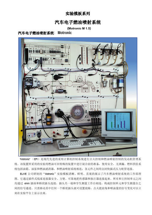
实验模板系列汽车电子燃油喷射系统(Motronic M 1.5)汽车电子燃油喷射系统: Motronic“Motronic”(EFI)是现代先进的采用计算机控制系统进行点火控制和燃油喷射控制的发动机管理系统。
该装置所采用的实验用燃油可在特殊的装置中进行混合前的准备,使用安全,无泄漏。
燃料供给系统包括油箱、油泵和燃油滤清器,和燃油喷射系统相连;各元件之间用自封快插式压力软管连接。
ELWE 公司研制的“Motronic”实验模板清晰、鲜明、直观的展示了汽车燃油喷射系统的工作原理图。
它通过插件式线束连接器安全、方便、可靠地把传感器和执行器连接起来。
所有和主控制单元之间均通过4mm插座和桥状插头连接,插头另一端和学生测量工作台相连,构成控制单元和学生测量台之间的信号通道。
只需移动其中任何一个桥状插头就可设置故障,点火提前角和喷油量的信号变化可以立刻在实验平台上显示出来。
对于排故训练,可以在线束和主控制单元之间连接一个故障模拟装置。
许多典型的汽车故障就可以以一种很隐蔽的方式输入到故障模拟器中去。
针对发动机动力系统的固定工况模式和工况过渡的教学实验,除采用车辆上的原装传感器外,也可使用可变信号模拟传感器。
如此则可在任何时候重复进行固定工况模式的检测。
ELWE 公司已经开发出用于车辆自动控制系统的界面和软件系统。
运用该软件,计算机可以方便地对检测和控制信号进行显示和分析。
该界面直接和诊断接口相连接,仅用于对控制系统的原始数据进行分析。
该控制系统实验模板有一个多项插座连接学生测量工作台。
每一名学生都可通过他的测量工作台独立地检测控制系统的输入和输出信号。
一个“Motronic ” 实验模板可以连接若干个学生测量工作台,非常方便于教学。
实验内容:1.Motronic 说明; 10. 空气流量计;2.Motronic 组成名称; 11. 节气门控制,强制怠速和满负荷加浓控制;3.线路图分析;12. 空燃比(λ)控制线路; 4.ELWE 实验模板结构简介; 13. 点火提前角特性图; 5.系统信号控制连接图; 14. 怠速控制系统; 6.自诊断系统——读取故障码; 15. 加速供油控制系统; 7.燃料供给系统检测;16. 霍尔传感器; 8.发动机转速和曲轴位置传感器; 17. 万用表检测排故;9.发动机水温传感器;18. PC 机控制实验系统检测排故;TG 3.275 Motronic M1.5 实验模板设备组成:P 3.0 电源连接电源大电流输出接线柱,钥匙开关可切断电源 尺寸(mm ): 99×297×170(W ×H ×D ) 重量: 1.05kg4位钥匙开关连接主电路和辅助电路尺寸(mm): 99×297×80(W×H×D)重量: 0.5kg4个火花塞,其中3个装在压力容器盒里,(连接压缩机和泄压阀)尺寸( mm): 159 x 297 x 105 (W x H x D)重量: 1.7 kg分电器由驱动马达(12V,20A)带动,惯性轮的速度控制在(0 ~7000r/min)之间,由一个2:1的减速齿轮驱动惯性轮。
电控燃油喷射系统

冷却液温度传感器
采用热敏电阻检测水温。传感器安装在发动机冷却水通路上,水温的变化将引起电阻值的变化,随水温升高,电阻值下降。 ECU中的电阻与水温传感器的热敏电阻串联,热敏电阻阻值变化时,所得分压值THW ,随之改变。
5.进气温度传感器
给ECU提供进气温度信号,作为燃油喷射和点火正时控制的修正信号。
一般而言,与传统的化油器发动机相比,装用电控燃油喷射系统的发动机功率提高5%一10%。燃料消耗降低5%一15%,废气排放量减少20%;由于扭矩特性的明显改善,瞬时响应快,汽车的加速性能大大提高,怠速平稳,冷车起动更容易,暖机更迅速。
燃油供给系统:汽油箱、电动汽油泵、汽油滤清器、燃油分配管、燃油压力调节器、喷油器。
内置式——安装在油箱中,具有噪声小、不易产 生气阻、不易泄漏、管路安装简单。 外置式——串接在油箱外部的输油管路中,易布置、安装自由大,但噪声大,易产生气阻。
按安装位置不同分为:
叶轮式、滚柱式、转子式和侧槽式,常用的为叶轮式、滚柱式。
按电动燃油泵的结构不同分为:
1.电动汽油泵
滚柱泵
当转子旋转时,位于其凹槽内的滚柱在离心力的作用下,紧压在泵体内表面上, 在相邻两个滚柱之间形成了一个空腔。在燃油泵运转过程中,一部分空腔的容积不断增大,成为低压油腔,将汽油吸入,而另一部分空腔容积不断减小,成为高压泵油腔,受压汽油流过电动机,通过出油口压出。
在一些有ISCV(怠速控制阀)的发动机中,没有此螺钉,ECU通过控制ISCV来实现对怠速转速的控制。
3、进气总管、进气歧管
SPI系统发动机采用中央喷射法,进气管形状与化油器式发动机基本一致。
SPI系统发动机进气管 (b) MPI系统发动机进气管
柴油机电控燃油动力系统外文文献翻译、中英文翻译、外文翻译
柴油机电控燃油动力系统外文文献翻译、中英文翻译、外文翻译Design of Diesel Engine Electronic Fuel Control System1.EUP Control MethodThe engine control unit is the most important component ofthe fuel n timing control system。
ensuring the n control requiredto achieve the minimum XXX of the camshaft n。
which is a measurement parameter of the crankshaft。
XXX。
The micro speed regulator (MCU) is controlled by the timer structure module (CTM) and the timing processing unit (TPU)。
When the timer structure module is interrupted by the camshaft trigger。
thecontrol component responds accordingly to the fuel supply system。
and the centralized maintenance module detects a XXX signal tothe timing processing unit (TPU)。
If there are Z teeth。
the span is 360o/z。
The pulse control unit is issued by the PSP and PMM。
The PSP has two working modes: angle-angle and angle-time。
喷射器制冷系统作为一种热驱动系统外文文献翻译、中英文翻译
外文文献Ejector refrigeration systems have long been an attractive research subject for a lot of researchers due to being heat- driven systems and having simple designs. Two importan drawbacks of these systems are primarily being refrigeration systems with low COP and using mechanically driven pumps. If the two disadvantages could be eliminated, especially the first one, the systems could find a wide area of application in air-conditioning and refrigeration industries. To produce a cooling effect, such heat-driven refrigeration systems could use low-grade energy sources, which are widely available and have low-cost such as solar and geothermal energy and waste heat. If the liquid pumps used in these systems could be ther- mally driven or an ejector refrigeration system without the pump could be developed, then the systems will be indepen- dent of electrical energy. In addition, the problems dealing with the operation of the pump and some additional devices coming with the pump will be eliminated. As expected, recent researches on the ejector refrigeration systems have focused on the improvement of energy conversion performance of these systems. Studies carried out to increase their efficien- cies are generally on a better design of ejector, the selection of a proper refrigerant, the optimization of operating condi- tions and the addition of various (secondary) devices such as a pre-cooler and regenerator to the refrigeration cycle. Scien- tists have densely studied on these research subjects for sev- eral decades and have achieved a significant improvement in the coefficient of performance of the systems using one or more methodsChang and Chen (2000) used a petal nozzle to enhance the performance of a steam-jet refrigeration system. According to their experimental results, when the system is operated at larger area ratios, the performance of system with a petal noz- zle is better than that with a conical nozzle.It is an attractive subject to develop an ejector refrigeration system without a liquid pump or with only thermal-driven. If this is achieved, such systems will not contain any moving part. For this purpose, Huang et al. (2006) have tried develop- ing an ejector cooling system with thermal pumping effect. The authors designed a cooling system with a multi-function generator which serves as both a liquid pump and a generator, thus eliminating a pump from system. These researchers tested the system and concluded that the design of such a sys- tem is feasible and it is possible to produce continuousl a cooling effect by regularly switching the two multi-function generators of the system.Eames (2002) introduced a new method for designing ejec- tors to be used in ejector refrigeration systems. It is assumed in the method that the momentum of flow changes at a con- stant rate within the diffuser passage of a supersonic ejector. The theoretical method produces a diffuser geometry that removes the thermodynamic shock process within the dif- fuser at the design-point operating conditions.Eames et al. (1999) examined the effects of ejector geometry on the performance of steam jet-pump refrigerators, using two primary nozzles and three diffusers with mixing chamber. It is seen from their experimental results that the entrainment ra- tio increases almost linearly with the ejector ratio area, if the primary pressure ratio ( pg/pc) and the ratio of the primary noz- zle exit area to throatarea (Ane/Ant) are held constant.Chunnanond and Aphornratana (2004) examined the ef- fects of the nozzle geometry and position on the performance of a steam ejector refrigerator with a conical mixing chamber. Based on their tests, they expressed that decreasing the gener- ator pressure, using a nozzle with smaller throat area (hence higher area ratio) and retracing the nozzle out of the mixing chamber can increase the COP and cooling capacity of the re- frigerator, provided that the critical condenser pressure is decreased.No matter what the working refrigerant, the type of ejector and the secondary devices are used in ejector refrigeration systems; it is required to optimize the operating conditions of the systems according to geometrical and flow parameters, to obtain maximum performance from them. Optimum oper- ating conditions of these systems mainly change depending upon the ejector area ratio (Nahdi et al., 1993; Yapıcı and Ersoy, 2005; Sun and Eames, 1996). In other words, when oper- ating temperatures or pressures were determined based on practical considerations such as heat source, refrigerated me- dium and heat rejected medium temperatures, an ejector should be designed so that its area ratio and nozzle position are optimum for the selected operating conditions. The aim of this study is to determine the optimized operating condi- tions of an ejector refrigeration system using R-123 in a wide In the first part of the study, primary vapor flow rates through these nozzles were measured at various generatortemperatures and then the optimum nozzle position for each area ratio was found separately by taking the minimum pressure at the suction chamber of the ejector as the criteria.In the second part of the study, it is described how the opti- mum operating condition is determined for a given area ratio To do this, as an example, the experimental results including the effects of operating temperatures or pressures on the COP of the system were also presented for the smallest area ratio6.5 in the present study. That is, three different experiments were conducted to find the optimum operating point for each area ratio. In consequence, the optimum generator tempera- ture for the area ratio was found at the evaporator temperature of 10 oC and the condenser pressure of 125 kPa.In the last part of the study, the optimum generator tem- peratures for the remaining five area ratios were determined separately by repeating experiments at the same evaporator and condenser conditions. It was seen that there exists only an optimum generator temperature for each area ratio. All ex- perimental curves showing variations in COP against the gen- erator temperature were totally presented on a graph and the optimum performance curve was generated as a function of the temperature. Moreover, the optimum experimental re- sults were compared with the optimized analytical results obtained for the same refriger ant by using the ejector flow model given in the literature (Yapıcı and Ersoy, 2005).The optimum COP almost linearly increases with the gen- erator temperature at the fixed evaporator and condenser conditions. The experimental curve of the optimum COP coin- cides with that of theoretical COP while the efficiencies of the primary nozzle and diffuser are 0.90.Fig. 1 schematically depicts the experimental setup. The main elements of the test facility are avapor generator, an ejector with movable nozzle, a condenser, a receiver tank, an expan- sion valve, an evaporator, a sub-cooler and a sliding vane pump; the refrigerant fluid circulates through the devices. The secondary elements of the refrigeration system are a hot water boiler, a circulating pump, pre-heater, through them which water flows, the measuring and control devices. The experimental setup and procedure, and the operation principle of the ejector refrigeration system are described in detail in the literature (Yapıcı, 2008).The output signals from the measurement devices were transferred to a PC through a data acquisition board and all readings were monitored and also recorded by the computer. All devices used for the measurement were calibrated to- gether with the data acquisition system in their measurement range. The pressure of the vapor generator was measured with the accuracy of 土10 kPa, whereas other pressures in the system were measured with the accuracies of 土1 kPa. The water flow rate of the evaporator was measured with an accuracy of 土0.03 L/min. The temperature of the vapor in the generator was measured with the accuracy of 土0.5 oC. Other temperatures were measured within 土0.2 oC accuracy. Based on the inaccuracies in measuring the temperature, vol- ume and time period, the uncertainty in the mass flow rate of the primary vapor is determined to be within 土4.8 %. The un- certainties in COP at the optimum operating conditions arewithin 土5.7%.The ejector model used in this study is shown in Fig. 2. In this model, inlet to the mixing chamber is with rounded- entry, the mixing chamber is of constant-area and the diffuser is conical. The ejectors were designed based on the constant- area ejector flow model given in the literature (Yapıcı and Ersoy, 2005; Ersoy, 1999). The configurations and dimensions of the six ejectors used in the experiments are presented in Table 1. These six configurations are obtained by using differ- ent three supersonic nozzles and two mixing chambers with diffusers.The coefficient of performance (COP) is the most important parameter for evaluating the performance of the ejector re- frigeration system. It indicates the cooling capacity relative to the energy input into the system. The energy input to the system in the refrigerant pump is too low compared with the energy input in the vapor generator. Therefore, neglecting the power of the liquid pump, the performance coefficient of the ejector refrigeration system is calculated from the follow- ing expression.COP (Qe/ Qg)/4(1)The cooling capacity was determined fromQ_ e ¼ m_ cwCpðTin — TexÞe(2)where m_ cw is the mass flow rate of chilling water.The heat input to the vapor generator was calculated fromQ_ g ¼ m_ pðhex — hinÞg (3)To determine the flow rates of primary vapor at various generator temperatures for each nozzle, the experiments were carried out and the mass flow rates of the primary nozzles were separately found as a function of the vapor generator temperature. Variations in the mass flow rate of primary vapor with thegenerator temperature are shown in Fig. 3 for three nozzles used in the experiments. Using the method of least squares, the m_ p——Tg curves were separately fitted to the experimental data for each nozzle. The equations of the curves were found and used in deter- mining the primary mass flow rates at the various generator temperatures.The relative nozzle position Ln/dm is in the range 0.5 < Ln/ dm < 2 according to the experimental results for refrigerant R-11 given in Nahdi et al. (1993). In the preliminary experi- ments carried out, similar results were found for ejector with the cylindrical mixing chamber at Pc ¼ 125 kPa, Pg ¼ 752.4 kPa (98 oC) and Ar ¼ 9.97, and using refrigerant R-123. Therefore, the nozzle position was adjusted toLn ¼ —5 mm (upstream the entry of cylindrical mixing cham- ber) in each experiment and the optimum generator tempera- tures were determined first separately by keeping evaporator and condenser conditions constant. After that, the variations of the suction chamber pressure with the nozzle position were measured at the optimum generator temperatures. Finally, it was controlled whether the adjusted nozzle distance is in the optimum range. The results for these experiments are shown in Fig.4. In determination of the optimum nozzle posi- tion, as in the literature (Hamner, 1978), the minimum pres- sure in the suction chamber was taken as criteria.It is clearly seen from the foregoing figure that the optimum range of the adjusted nozzle position for all nozzles is within —10 to 5 mm.When the condenser and evaporator temperatures/ pressures are known, it is possible to find the optimum gener ator temperature for a given ejector area ratio. In this study, he evaporator temperature is selected as 10 oC, which is ppropriate for air-conditioning. To ensure the operation of he system at the choked operating conditions even at the smallest ejector area ratio, the condenser pressure is taken as 125 kPa (saturation temperature nearly 34 oC). As an exam- ple, the result of experiment carried out to determine the optimum generator temperature is shown in Fig. 5 for the ejector area ratio Ar ¼ 6.56. The maximum COP for this area ratio was obtained at Tg ¼ 83 oC and hence the temperature is optimum generator temperature.In order to determine the critical condenser pressure and hence to control whether the ejector operates at the condi- tions with choking in the mixing chamber, the variation of COP with condenser pressure is investigated at Tg ¼ 83 oC and Te ¼ 10 oC. According to the curve shown in Fig. 6, the crit- ical condenser pressure is about 126 kPa and thus operating point of the ejector is very near the critical operating condi- tion, that is, the system operates in maximum cooling capac- ity at the given area ratio.Fig. 7 shows how COP changed with the evaporator tem- perature at the same area ratio. Actually, this last experiment for the area ratio was done to verify the COP value at the opti- mum operating condition specified above. Thus the experi- mentation at an operating point becomes repeated three times. Referring to Fig. 7, we see that COP value at Te ¼ 10 oC is about 29% again. On the other hand, COP increasing with the evaporator temperature is an expected result under such operating conditions.The experimental procedure described above was repeated for the remaining five ejectors and the COP–Tg curves were de- termined experimentally for the six area ratios and are all shown in Fig. 8 by different marks. From these curves, it is clearly seen that an optimum generator temperature for everyarea ratio exists at the fixed evaporator and condenser tem- peratures. As shown in the same figure, the optimum COP curve is the line which is a tangent to the peaks of COP–Tg curves. Optimum COP increases nearly linearly with the opti- mum generator temperature. The value of COPopt reaches to around 41% at the area ratio 11.45 from 29% at the area ratio6.56. Based on the results shown in Fig. 7, it can be expressed that a higher COPopt can be obtained by increasing the evapo- rator temperature. Other important result which should be expressed here is that the slope of COP–Tg for a given area ratio is too high at lower temperatures than the optimum generator temperature. Therefore, if the difference between the optimum and operating temperatures of the generator at an area ratio is higher than a given value, which is around 10 oC here, the system does not achieve its function.Comparison of the optimum experimental results with optimum theoretical results is presented in Fig. 9 for the same operating conditions. The optimum theoretical results were determined for three different efficiencies of ejector elements, using the methods provided in literature (Yapıcı and Ersoy, 2005). To obtain these theoretical results, efficien- cies of the supersonic nozzle and diffuser were kept constant at the values shown in Fig. 9. When the efficiencies were 90%, the experimental data agree very well with the theoretical data.Fig. 10 shows variations of the optimum experimental and theoretical area ratios with the generator temperature. According to both experimental and theoretical results, the optimum area ratio increases almost linearly with the temper- ature. In other words, a lower generator temperature means a smaller ejector area ratio. To obtain a higher COP at a fixed generator temperature, the ejector area ratio should be in- creased together with efficiencies of ejector elements. More- over, the theoretical results for efficiencies of 90% agree with the experimental results. The theoretical area ratios are just slightly higher than the experimental ratios.中文文献喷射器制冷系统作为一种热驱动系统,由于其设计简单,长期以来一直是许多研究者关注的研究课题。
柴油电控技术外文文献翻译、中英文翻译、外文翻译
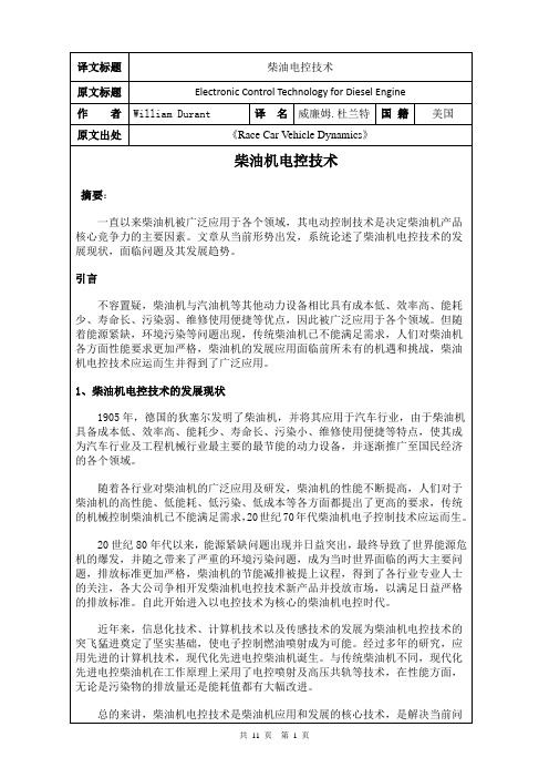
20世纪80年代以来,能源紧缺问题出现并日益突出,最终导致了世界能源危机的爆发,并随之带来了严重的环境污染问题,成为当时世界面临的两大主要问题,排放标准更加严格,柴油机的节能减排被提上议程,得到了各行业专业人士的关注,各大公司争相开发柴油机电控技术新产品并投放市场,以满足日益严格的排放标准。自此开始进入以电控技术为核心的柴油机电控时代。
3、结语
近年来柴油机电控技术的发展令人瞩目,但是所面临的问题也不容忽视。只有不断深化对电控技术理论研究及相关产品研发,才能适应新的要求,使柴油机在国民经济发展中继续发挥核心作用。
Electronic Control Technology for Diesel Engine
Abstract:
Diesel has been widely used in various areas of China's economic construction. Electric control technology of diesel is the main factor determined the core competitiveness of diesel products. From the current situation, the paper discussed the development status, the facing problems and the development trends of diesel electronic control technology.
中英文文献翻译—燃油喷射系统及点火系统
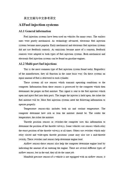
英文文献与中文参考译文A1Fuel injection systemsA1.1 General informationFuel injection systems have been used on vehicles for many years. The earliest ones were purely mechanical. As technology advanced, electronic fuel injection systems became more popular. Early mechanical and electronic fuel injection systems did not use feedback controls. As emissions became more of a concern, feedback controls were adapted to both types of fuel injection systems. Both mechanical and electronic fuel injection systems can be found on gasoline engines.A1.2 Multi-port fuel injectionsThis is the most common type of fuel injection system found today. Regardless of the manufacturer, they all function in the same basic way. On these systems an equal amount of fuel is delivered to each cylinder.These systems all use sensors which transmit operating conditions to the computer. Information from these sensors is processed by the computer which then determines the proper air/fuel mixture. This signal is sent to the fuel injectors which open and inject fuel into their ports. The longer the injector is held open, the richer the fuel mixture will be. Most fuel injection systems need the following information to operate properly.Temperature sensors-this includes both air and coolant temperature. The computer determine how rich or lean the mixture should be. The colder the temperature, the richer the mixture.Throttle position sensors or switches-the computer uses this information to determine the position of the throttle valve(s). Some vehicles use sensors which relay the exact position of the throttle valve(s) at all times. Others use switches which only relay closed and wide-open throttle positions (some may also use a mid-throttle switch). These switches and sensors help determine engine load.Airflow sensors-these sensors also help the computer determine engine load by indicating the amount of air entering the engine. There are several different types of airflow sensors, but in the end, they all do the same job.Manifold pressure sensors-if a vehicle is not equipped with an airflow sensor, ituses a manifold pressure sensor to determine engine load (Note that some vehicles with an airflow sensor may also have a manifold pressure sensor. This is used as a fail-safe if the airflow sensor fails). As engine load increases, so does intake manifold air pressure.Engine speed and position sensors-engine speed/position sensors can be referenced form the crankshaft, camshaft or both. In addition to helping determine engine load, these sensors also tell the computer when the injectors should be fired.These systems operate at a relatively high pressure(usually at least 30 psi). To control the fuel pressure, a fuel pressure regulator is used. As engine load increases, more fuel pressure is needed. This is due to the richer mixture (more fuel needed) and to overcome the increased air pressure in the ports. Any unused fuel is diverted back to the fuel tank using a return line.A2. Ignition systemThere are many different types of ignition systems. Most of these systems can be placed into one of three distinct groups: the conventional breaker point type ignition systems (in use since the early 1900s); the electronic ignition systems (popular since the mid 70s); and the distributorless ignition system (introduced in the mid 80s).The automotive ignition system has two basic functions: it must control the spark and timing of the spark plug firing to match varying engine requirements, and it must increase battery voltage to a point where it will overcome the resistance offered by the spark plug gap and fire the plug.A2.1How does the ignition system workAn automotive ignition system is divided into two electrical circuits—the primary and secondary circuits. The primary circuit carries low voltage. This circuit operates only on battery current and is controlled by the breaker points and the ignition switch. The secondary circuit consists of the secondary windings in the coil, the high tension lead between the distributor and the coil (commonly called the coil wire) on external coil distributors, the distributor cap, the distributor rotor ,the spark plug leads and the spark plugs.The distributor is the controlling element of the system. It switches the primary current on and off and distributes the current to the proper spark plug each time a spark is needed. The distributor is a stationary housing surrounding a rotating shaft.The shaft is driven at one-half engine speed by the engine’s camshaft through the distributor drive gears. A cam near the top of the distributor shaft has one lobe for each cylinder of the engine. The cam operates the contact points, which are mounted on a plate within the distributor housing.A rotor is attached to the top of the distributor shaft. When the distributor cap is in place, a spring-loaded piece of metal in the center of the cap makes contact with a metal strip on top of the rotor. The outer end of the rotor passes very close to the contacts connected to the spark plug leads around the outside of the distributor cap.The coil is the heart of the ignition system. Essentially, it is nothing more than a transformer which takes the relatively low voltage (12 volts) available from the battery and increases it to a point where it will fire the spark plug as much as 40000 volts. The term “coil” is perhaps a misnomer since there are actually two coils of wire wound about an iron core. These coils are insulated from each other and the whole assembly is enclosed in an oil-filled case. The primary coil, which consists of relatively few turns of heavy wire, is connected to the two primary terminals located on top of the coil. The secondary coil consists of many turns of fine wire. It is connected to the high-tension connection on top of the coil (the tower into which the coil wire from the distributor is plugged).Under normal operating conditions, power from the battery is fed through a resistor or resistance wire to the primary circuit of the coil and is then grounded through the ignition points in the distributor (the points are closed). Energizing the coil primary circuit with battery voltage produces produces current flow through the primary windings, which induces a very large, intense magnetic field. This magnetic field remains as long as current flows and the points remain closed.As the distributor cam rotates, the points are pushed apart, breaking the primary circuit and stopping the flow of current. Interrupting the flow of primary current causes the magnetic field to collapse. Just as current flowing through a wire produces a magnetic field, moving a magnetic field across a wire will produce a current. As the magnetic field collapses its lines of force cross the secondary windings, inducing a current in them. Since there are many more turns of wire in the secondary windings, the voltage from the primary windings is magnified considerably up to 40000 volts[18,19].参考译文:A1.燃油喷射系统A1.1 燃油喷射系统概述燃料喷射系统已经在汽上车使用了许多年。
大众轿车电子燃油喷射系统【毕业论文,绝对精品】

摘要本文介绍电控燃油喷射系统的发展,讲述电控燃油喷射系统的功用,组成和工作原理,介绍了故障诊断的基本原则,还介绍了电子燃油喷射同的一般优点和特点,以及电控燃油喷射系统的常见故障,电子燃油喷射系统透彻的分析了常见的故障原因和解决方法。
用科学的方法去对汽车的故障解决,这样就可以解决现代汽车给人带来的麻烦一下子解决,缩短了时间和经历使维修走上了科学正规的道路。
总结出电控燃油喷射系统常见故障的诊断与排除过程。
以大众轿车电控燃油喷射系统为例,有针对性的讲述电控燃油喷射系统常见故障的诊断与排除步骤。
还给大家介绍了汽车未来的发展方向还阐述了汽车必将以后走电子化道路。
汽车电子化可以给人类带来许多的方便和便捷。
让我们的生活更加的美好让我们感谢电子化给我们带来的快乐。
关键词:电控燃油喷射系统,常见故障,排除前言随着现代交通工具的发展交通工具交通工具是现代人的生活中不可缺少的一个部分。
随着时代的变化和科学技术的进步,我们周围的交通工具越来越多,给每一个人的生活都带来了极大的方便。
陆地上的汽车,海洋里的轮船,天空中的飞机,大大缩短了人们交往的距离。
交通工具狭义上指一切人造的用于人类代步或运输的装置。
如:自行车,汽车,摩托车,火车,船只及飞行器等。
其中也包括马车,牛车等动物驱动的移动设备,从这一点来说,黄包车、轿子也可以算是交通工具。
最原始的交通工具是人的双脚。
然后人类就驯服一些动物如马、驴子等作为乘坐工具或乘坐工具的动力(如:马车),与此同时,轿子和以风作为动力的帆船也作为一种交通工具与畜力交通工具长期并存。
以人力、畜力和风力作为动力的交通工具占据了人类历史的绝大部分时间。
直至蒸汽机的出现,人类交通工具的发展才进入飞速发展阶段,短短数百年,人类不仅能上天。
交通工具的发展分为四个阶段,分别为蒸汽阶段、内燃阶段、电气阶段、自动化阶段。
蒸气阶段为英国产业革命时期,代表性的交通工具为蒸气火车、蒸气轮船等,现在已经基本淘汰。
中国的蒸气火车于去年十月正式退出历史舞台,当时中央电视台的社会记录啊丘还对此有所报道。
电子控制燃料喷射_OK

(가)空气旁通道电磁阀(Air By-Pass Solenoid) (나)怠速控制执行器 (다)旁通道控制阀
(3)步进电机式 (4)ISC-伺服机
33
从空气滤清器来 遮门
空气阀 (Air Valve)
(가)双金属片式空气阀
遮门
往进气总管 电热线
F E E2 VVC VS THA
发动机静止时
进气量 多 少
测量叶片 大 小
测量叶片
发动机工作时
Vs:电压 高 低
11
AFS-空气流量计
减震室 平衡叶片
减震室
有减震室时
震
动
角
度
无减震室时
时间
12
空气流量计(Vane Type)
(1)旁通系统 (By-Pass System)
空气流量计 空气调整螺钉 节气门阀体
气压缓冲室
旁通道调整螺钉
空气阀
空气滤清器 空气流量计 节气门阀体 进气总管
发动机
空气阀 怠速阀
旁通空气量 检测后的空气
发动机
A.A.S(Air Adjust Screw)
P.K.H13
热线式空气流量传感器
(Hot-
Wire Air Flow Sensor)
☺热线式空气流量传感器比叶片式空气流量计
有以下优点.
(나)怠速控制执行器
(1)电磁式执行器 线圈 阀轴
阀门 负压消除用
波纹管
阀门
(2)转子式 弹簧
接线端子
空气出口 空气吸入口
永久磁铁 电磁线圈 电枢
旁通道 旋转滑阀
空气出口
空气入口
外文翻译--喷射系统中文版-精品
摘自2004年9/10月《Automotive Design Asia》喷射系统Jeff Daniels摘要柴油喷射压力已提高到2000巴,汽油直喷和压电技术都变得越来越常见,因为燃油供给系统在不断地改革。
大约在过去的五年中,汽车燃油供给技术发生了一场革命,其中变化最大的是柴油发动机,在直喷柴油机上运用了共轨系统,该系统安装有压电式喷油器,现在正受到人们越来越多的关注。
在汽油发动机方面,现在也有往直喷技术发展的趋势,但这种趋势逐渐趋缓,而且并没有都往这个方向发展,也有其它新的技术,诸如空气引射技术,但受材料方面的影响进展也较缓慢。
任何燃油供给系统最基本的功能是向每个汽缸供给足够的燃油,通过这种方式与吸进来的空气混合并燃烧,当然,燃烧得越完全越好。
随着对汽车排放要求的提高,对该方面的更精确控制变得很有必要。
燃油供给系统不仅要改变循环供油量,同时要改变喷油正时和喷油位置。
在90年代中期,化油器式的汽油机各项性能还能基本达到要求,该技术是把然油和空气在进气歧管前混合,当进气门打开后,可然混合气流经进气歧管吸入气缸,但该技术在控制方面并不精确。
之后化油器的大量改进针对的目标首先是完美地控制每个气缸混合气的浓度和量,其次是克服系统高惯性的操空缺点,再次是完成良好的混和与完全燃油燃烧。
达到排放法规所规定的排放标准需要三元催化转换器,所以法规一出台,化油器变成为了历史。
有效的操作应该是应该是控制可然混合气浓度,即在大多数情况下把浓度控制在理论空燃比附近。
结果燃油喷射变得强制性了。
欧洲没有采用美国早期的解决方法(燃油在喉管喷射),而是致力于开发在每个气缸安装一个喷油器的独立喷射技术。
所有喷油器同步工作技术在90年代早期较为普遍,在配有优化正时技术时,但是和排放方面的有些要求必须大量采用该方法。
此后,问题成为解决方法应该向哪个技术方向发展。
解决方案不断出现:燃油经济性和低排放驱动了欧洲排放法规向前迈进。
通过提高压缩比来提高热效率的任何解决方法,只要排放达标,都被受视为可行的。
发动机主要零部件中英文对照——电子燃油喷射系统电路图
发动机主要零部件中英文对照——电子燃油喷射系统电路图佚名
【期刊名称】《汽车与驾驶维修:汽车版》
【年(卷),期】2001(0)5
【摘要】1.fuel pump 燃油泵2.TDCL 自诊断系统监控器3.fuel pump ECU 【总页数】1页(P75-75)
【关键词】燃油泵;电子燃油喷射系统;主要零部件;自诊断系统;电控单元;监控器;发动机;英文对照;电路图;爆震传感器
【正文语种】中文
【中图分类】U464
【相关文献】
1.发动机电控燃油喷射系统主要部件的检测 [J], 张树东
2.发动机主要零部件中英文对照电子燃油喷射系统电路图 [J],
3.发动机主要零部件中英文对照 [J],
4.发动机主要零部件中英文对照 [J],
5.发动机主要零部件中英文对照 [J],
因版权原因,仅展示原文概要,查看原文内容请购买。
- 1、下载文档前请自行甄别文档内容的完整性,平台不提供额外的编辑、内容补充、找答案等附加服务。
- 2、"仅部分预览"的文档,不可在线预览部分如存在完整性等问题,可反馈申请退款(可完整预览的文档不适用该条件!)。
- 3、如文档侵犯您的权益,请联系客服反馈,我们会尽快为您处理(人工客服工作时间:9:00-18:30)。
附录附录A 英文文献与中文参考翻译In the 1970s introduced electronic controls fuel injection system with high performance, it can meet the modern automobile to except the strict request discharge, saving, increase in power, to improve performance and many other aspects accelerating its advantages, gradually replacing carburetor and extensive use, is the inevitable trend of the future.In EFI system, a fuel common faults mainly has: the ignition switch, pump, oil pump does not turn the oil pipeline, not too high or too low, hydraulic injection fuel nozzle nozzle, no oil leakage or drops of oil, fuel nozzle and tubing connection or the intake manifold junction leakage, and cold start-up nozzle doesn't work, etc. The following simple introduction of these faults and eliminate.(1)oil pump oil or notThe ignition switch, pump can turn or pump oil, the main causes of the following: (1) if the engine running, because the air flow has not moved, and the impeller of it is not connected to pump switches to L (EFI system), or distributor in speed signal transmission to the electronic controller (ECU) (EFI system for D) : 2) pump drive circuit relay or main contactor relays disconnect circuit breakers, or coil ablation, 3) pump power input, or the power plug contact undesirable conductor disconnected, 4) pump brush, brush spring break or wear loses elasticity: 5) of the armature winding burning oil: 6) pump wheels stuck. For this failure, should press following method for checking and removing: check whether the oil pump, electric in through the ignition switch engine running, not after the press the pump drive circuit switch, such as oil pump check and its driving circuit itself without fault, pump should be able to turn and oil pump. If pump, should first turn not check whether the power plug pump, or loose wires connecting the disconnect, this is the most common causes of malfunction, also more easily. Further, including driving circuit can check to the failure of the ignition switch, fuse is, the relay, power supplies, and such as relays disconnect the plug and wires connecting them. The relay contacts ablation, electromagnetic winding drive circuit broken will affect the burn, pump can rotate. If contact ablation is not serious, can repair, or by burnish should replacement parts. Final inspection pump itself, can use digital multimeter measurement of the oil pump motor armature, normally it's resistance to 12 ~15n, if the measurement result is somewhat larger, probably due to plug, attachment areas such as poor contact, or brush wear. If the measured value is infinite, you must have been burned armature winding is broken. Because of the pump is whole package, cannot open repair, so should be replaced. After the examination, and in different parts of the normal circumstance, still appear likely engine running, don't turn pump is due to the air flow pump switches have caused by fault, switch contact undesirable, can cause failure attachment breakers. Through the inspection pump switches, easily find fault.(2)pump rotation but not pump oilPump rotation but not pump oil, mainly composed of the following reasons: 1) the pump pressure valves, or stuck roof-floor valve spring break, make discharging pressure valves, pumps have often open the oil pump flow back, but only to the tank can pump pressure pipe in fuel, 2) of the oil pump fitting stuck out of oil pump, not by pressing pressure oil pressure valves only by return tank, 3) the pump JinYou blocked, or JinYou mesh seere blockages, make the pump suction resistance due to too much and cannot pump out fuel, 4) pump impeller and pump shell with serious wear, mutual exist great gap, cannot be fuel pump. To avoid this problem, should strictly in accordance with the requirements of operation and maintenance, cleaning, cleaning tank on screen, avoid jam phenomenon. To check or discharging pressure valves, slight delay card can use the method to eliminate keystrokes and vibration. If you have severe worn or damaged parts of the situation, it should be replaced pump.(3)fuel pressure lowFrom the oil pump output to fuel pressure should be 0.27-0.30 MPa. Low pressure will seriously affect the fuel injection quantity measurement, to reduce power down, causing difficulty, starting to engine performance. Low pressure caused by the reasons for oil pump, valve, pressure from 0 - or - to valve leakage, JinYou filter clogging pump impeller and, wear, and fuel filters in oil, are the factors should be taken into consideration. Another to consider is the regulator, if the voltage regulator, the diaphragm spring is damaged, soft, seating damage caused by oil pressure will be low. If the above situation, should replace the regulator.(4)fuel pressure is too highPressure regulator is caused by excessive stiffness spring is the main reason for the high pressure difference, if the standard with excessive, will make the injection quantity,causing the mixture, now should replace pressure regulator. In addition, pressure regulator and the intake manifold connection pipe leakage, make its cannot feel intake manifold vacuum, will cause the compensating mixture too thick. Through the careful installation of connection lines and often check, can avoid such failure.(5)cold start-up nozzles.such workCheck whether the cold start nozzle can work normally, it should be removed from the inlet connection, with the special tools to coiled tubing connection with the cold start nozzle together, reoccupy interconnects socket and special tools to both the battery. Note battery anode, positive line only even in my hand, and in a very short time point of contact battery anode piles, if the cold start nozzle is good, it will be a brief jet fuel. Otherwise, shall check the cold start nozzle, main is to check whether the magnetic coil. Using a multimeter to check the magnetic coil, the resistance should be in 3-5 Ω, if the resistance, that the magnetic coil is burning. If the cold start nozzle is good, but do not spray, should check whether the normal temperature switches. Using the multimeter to test its two ends, wiring resistance should be 20-50 Ω, if reach 50-60 Ω that its internal contacts have closed loop, nozzle coil current, cause not spray. Note that if the environment temperature over 40 ° C, the temperature of the time switch contacts open attribute normal phenomenon.参考译文:20世纪70年代推出的电子控制燃料喷射系统具有优良的性能,它除了可以满足现代汽车对排放、节油的严格要求外,还在增大功率、改善加速性能等许多方面具有优势,其逐步取代化油器而广泛使用,是今后的必然趋势。