609伺服阀样本
609伺服阀样本
609伺服阀样本1. 引言伺服阀是一种用于控制液压系统的重要元件。
它通过调节流体的流量和压力来实现对液压系统的精确控制。
609伺服阀是一种常见的伺服阀样本,广泛应用于工业自动化、机械加工和航空航天等领域。
本文将对609伺服阀样本的结构、工作原理和应用进行全面介绍。
2. 609伺服阀样本的结构609伺服阀样本由阀体、阀芯、控制电磁铁和传感器等组成。
阀体是伺服阀的外壳,通常由高强度的金属材料制成,以确保阀体的耐压性能。
阀芯是伺服阀的核心部件,负责控制液压系统的流量和压力。
控制电磁铁通过电流的开闭来控制阀芯的运动,从而实现对液压系统的精确控制。
传感器用于检测液压系统的状态,将反馈信号传输给控制电磁铁,以实现闭环控制。
3. 609伺服阀样本的工作原理609伺服阀样本基于液压控制原理工作,其工作原理如下:1.当液压系统工作时,控制电磁铁通电,产生磁场。
磁场作用于阀芯上的铁芯,使阀芯向一侧运动。
2.阀芯运动时,改变了阀芯与阀体之间的通道,使液体流量发生变化。
同时,阀芯的位置也会改变液压系统的压力。
3.传感器检测液压系统的状态,并将反馈信号传输给控制电磁铁。
控制电磁铁根据反馈信号的大小和方向来控制电流的开闭,从而调节阀芯的运动。
4.通过不断调节阀芯的位置,伺服阀可以实现对液压系统的精确控制,使系统能够按照要求的速度和力量进行工作。
4. 609伺服阀样本的应用609伺服阀样本广泛应用于各个领域,具有以下几个主要应用:4.1 工业自动化在工业自动化领域,609伺服阀样本常用于控制机械设备的运动。
例如,在汽车生产线上,伺服阀可以精确控制机械臂的运动,实现对汽车零部件的装配。
在食品加工生产线上,伺服阀可以控制输送带的速度和位置,确保食品的准确分拣和包装。
4.2 机械加工在机械加工领域,609伺服阀样本常用于控制数控机床的运动。
伺服阀可以实现对刀具的进给速度和切削力的精确控制,从而提高加工精度和效率。
此外,伺服阀还可以控制机床的进给轴和主轴的运动,实现对工件的复杂加工。
MOOG伺服阀及其各种伺服阀型号概要

供应MOOG穆格伺服阀D691-072D/Q08FBAABNVS0N型号:其中MOOG是为伺服阀,而D691-072D是直动式伺服阀的型号。
以下是各种伺服阀及其动能作用,希望对你有帮助。
Moog伺服阀 G631-3002BMoog伺服阀 G631-3004BMoog伺服阀 G631-3006BMoog伺服阀 G761-3003-5Moog伺服阀 G761-3009AMoog伺服阀 G761-3602Moog伺服阀 G761-3605Moog伺服阀 G040-123-001Moog伺服阀 D792-5002Moog伺服阀 D791-5045Moog伺服阀 D791-5021Moog伺服阀 D791-5008Moog伺服阀 D765-1603-5Moog伺服阀 D765-1048-5Moog伺服阀 D664Z4382KMoog伺服阀 D664Z4306KMoog伺服阀 D664-4714Moog伺服阀 D664-4384KMoog伺服阀 D664-4383KMoog伺服阀 D664-4311KMoog伺服阀 D664-4013Moog伺服阀 D664-4009Moog伺服阀 D663Z4322KMoog伺服阀 D663Z4307KMoog伺服阀 D663Z4305KMoog伺服阀 D663-5002Moog伺服阀 D663-4769Moog伺服阀 D663-4705Moog伺服阀 D663-4025Moog伺服阀 D663-4318KMoog伺服阀 D663-4007Moog伺服阀 D663-4012Moog伺服阀 D663-306K Moog伺服阀 D663-1922E-4 Moog伺服阀 D662Z4815 Moog伺服阀 D662Z4814 Moog伺服阀 D662Z4813 Moog伺服阀 G761-3009A Moog伺服阀 D662Z4336K Moog伺服阀 G761-3605 Moog伺服阀 D662Z4380 Moog伺服阀 D662Z4384K Moog伺服阀 D662Z4341K Moog伺服阀 M040-104B Moog伺服阀 G040-123-001 Moog伺服阀 D662-4038 Moog伺服阀 D661-4652 Moog伺服阀 D661-4313C Moog伺服阀 D661-4332C Moog伺服阀 D661-4334C Moog伺服阀 D661-4438E Moog伺服阀 D661-4451C Moog伺服阀 D661-4507C Moog伺服阀 D661-4575C Moog伺服阀 D661-4576C Moog伺服阀 D661-4586E Moog伺服阀 D661-4594C Moog伺服阀 D661-4624 Moog伺服阀 D661-4636 Moog伺服阀 D661-4640 Moog伺服阀 D661-4649 Moog伺服阀 D661-4650 Moog伺服阀 D661-4651 Moog伺服阀 D661-4652 Moog伺服阀 D661-4691C Moog伺服阀 D661-4697CMoog伺服阀 D661-4773 Moog伺服阀 D661-4776 Moog伺服阀 D661-4782 Moog伺服阀 D661-4790 Moog伺服阀 D661-4826 Moog伺服阀 D661-4867 Moog伺服阀 D661-5611 Moog伺服阀 D661-5625C Moog伺服阀 D662-1923E-4 Moog伺服阀 D662-4010 Moog伺服阀 D662-4014 Moog伺服阀 D662-4036 Moog伺服阀 D662-4037 Moog伺服阀 D662-4038 Moog伺服阀 D662-4065 Moog伺服阀 D662-4083 Moog伺服阀 D662-4099 Moog伺服阀 D662-4723 Moog伺服阀 D662-4846 Moog伺服阀 D662-4884 Moog伺服阀 D662Z1931E Moog伺服阀 D662Z4017 Moog伺服阀 D662Z4336K Moog伺服阀 D662Z4341K Moog伺服阀 D662Z4378K Moog伺服阀 D662Z4380 Moog伺服阀 D662Z4384K Moog伺服阀 D662Z4813 Moog伺服阀 D662Z4814 Moog伺服阀 D662Z4815 Moog伺服阀 D663-1922E-4 Moog伺服阀 D663-306K Moog伺服阀 D663-344K Moog伺服阀 D663-4007Moog伺服阀 D663-4025 Moog伺服阀 D663-4318K Moog伺服阀 D663-4705 Moog伺服阀 D663-4769 Moog伺服阀 D663-5002 Moog伺服阀 D663-5304K Moog伺服阀 D663Z4305K Moog伺服阀 D663Z4307K Moog伺服阀 D663Z4322K Moog伺服阀 D664-4009 Moog伺服阀 D664-4013 Moog伺服阀 D664-4311K Moog伺服阀 D664-4383K Moog伺服阀 D664-4384K Moog伺服阀 D664-4714 Moog伺服阀 D664Z4306K Moog伺服阀 D664Z4382K Moog伺服阀 D765-019-5 Moog伺服阀 D765-1048-5 Moog伺服阀 D765-1603-5 Moog伺服阀 D791-5008 Moog伺服阀 D791-5045 Moog伺服阀 D791-5021 Moog伺服阀 D792-5002 Moog伺服阀 G040-123-001 D661-4651D661-4652D661-4636D661-4469CD661-4697CD661-4033D661-4059D661-4444CD661-4443CD661-4506CD661-4539CD662Z4311KD662-4010D662Z4336KD663Z4307KD663-4007D663Z4307KD663-4007D634-341CD634-319CD633-333BD791-5009D791-4025D791-4001D791-4002D791-4028D791-4046072-559AD633-312BD633-442BD633-526BD633-419BD633-473BD633-500BD633-314AD633-333BD633-442BD633D633-D2500BD633-D2501BD633-362B/穆格滤芯A67999-065 穆格滤芯A67999-100 穆格滤芯A67999-200穆格滤芯A88594-004 B46634-002B46744-004B61042-005B67728-001B96839-001B97007-061B97027-012B97036-001B97067-111B97069-061C70935-001D631-502FD631-F550FD633-183BD633-303BD633-308BD633-313BD633-315BD633-317BD633-333BD633-380BD633-460BD633-471BD633-472BD633-473BD633-481BD633-495BD633-Z371BD633-501BD633-525BD633D2504BD633-599BD633-603BD634-1035D634-1063D634-400CD634-501AD634-538AD634-543AD634K2000C D635-671ED635-Z681E D691-069DD691-072D-7 D636-225-0000 D661-4003D661-393DD661-4009D661-4023D661-4059D661-4051D661-4055D661-4033D661-4069D661-4070D661-4099D661-4157BD661-4158BD661-4168D661-4178D661-4186D661-4187D661-6405CD661-4303ED661-4313CD661-4332CD661-4334CD661-4341CD661-4438E D661-4443C D661-4444C D661-4451C D661-4506C D661-4507C D661-4575C D661-4576C D661-4577C D661-4586E D661-4594C D661-4624 D661-4636 D661-4640 D661-4649 D661-4650 D661-4651 D661-4652 D661-4688C D661-4691C D661-4697C D661-4729 D661-4773 D661-4776 D661-4782 D661-4790 D661-4826 D661-4867 D661-4931 D661-5611 D661-5625C D661-6313C D661-6324 D661-6326D661-6359D661-6347CD661-6393CD661-6397CD661-6360D661-6372ED661-6428ED662-1923E-4D662-4005 D01HABF6VSX2 D662-4032D662-4010D662-4013D662-4014D662-4036D662-4037D662-4038D662-4050D662-4065D662-4087D662-4083D662-4099D662-4106BD662-4115D662-4118BD662-4124D662-4723D662-4846D662-4884D662-4930D662Z1931ED662Z4017D662Z4310KD662Z4334D662Z4336KD662Z4341K D662-Z4372A D662Z4378K D662Z4380D662Z4384K D662Z4615K D662Z4813D662Z4814D662Z4815D663-1922E-4 D663-306KD663-344KD663-4002D663-4006D663-4007D663-4012D663-4025D663-4031D663-4317D663-4318K D663-4705D663-4769D663-5002D663-5304K D663Z4305K D663Z4307K D663Z4322K D664-4009D664-4013D664-4036D664-4039D664-4311K D664-4383K D664-4384KD664-4714D664-4784D664Z4306KD664Z4382KD664Z4406KD671-0039-0001 D671-0040-0001 D671-0051-0001 D671-0052-0001 D671-0068-0001 D671-0070-0001 D672-0006-0000 D672-0013-0001 D672-0026-0001 D672-0027-0001 D672-0028-0001 D672-0036-0001 D672-0037-0001 D672-5706-0001 D673-0001-0000 D673-5702-0001 D673-5705-0001 D674-0015-0001 D674-5706-0001 D675-5704-0001 D675-5705-0001 D682Z4059D682Z4060D683-4822D683Z4010D684-4912D684Z4011D685-4837DD685-4868D765-019-5D765-1048-5D765-1603-4D765-1603-5D791-5008D791-5021D791-5045D792-4013/S99JOQA6VSX2-B D792-5002D792-5018G040-123-001G631-3002BG631-3004BG631-3005BG631-3006BG631-3008BD636-312-0001D636-313-0001D683-4834G761-3033BG761-3003B5G761-3005BG761-3004B5G761-3009BG761-3602BG761-3605BM040-104BD951-2025-10D951-2007-10D951-2009-10D951-2079-10D952-2001-10D952-2007-10D952-2009-10D953-2001-10D953-2015-10D953-2017-10D954-2003-10D954-2011-10D954-2013-10D955-2003-10D955-2013-10D955-2017-10D956-2003-10D956-2015-10D956-2011-10D956-2017-10D957-2003-10J761-003J761-004G122-824-002072-560AD691-069DD635-671ED691-072DD062-512F760F911A-HP5?S10K0GM4VPL D633-632D663-339NC072-560A,替代型号072-1203-9 D635-671ED061-9321D061-823C072-1202-100514 RKP 柱塞泵G631-3705BD662-3303K P01HLMF6NEC2-0 D638-206-0001D638-216-0001G122-202A001L129-034-A007(S/N)L103G122-829-001G122-829-001G123-825-001G761-3001BD684-4915G631-3800BG771K202 S19FOFA4VA4G771K200 S19FOFA4UI4G771K208 S02FOFA4VA4G771K200 H19FOFA4VI4G771K202 H19FOFA4V24G771K208 H02FOFA4V24G772K240 S38FOFA4V14D691-078D-6D953-2017/c HP-RKP045KM28111Z200D952-2001-10 HPR18A1 RKP032KM28J1Z00D952-2007-10 HPR18A1 RKP032KM28F2Z00D955-2017-10 HPR18A1 RKP080KM28J1Z00D955-2003-10 HPR18A1 RKP080KM28F2Z00D634直动式伺服阀MOOG D634,直动阀(DDV)是具有内部阀芯位置电反馈的伺服阀。
MOOG伺服阀D660 的中文样本

多级阀的工作原理
主阀芯的位置闭环控制是由集成电子装置来实现的。 一个电气指 令信号 ( 用来设定流量 ) 作用于集成电路位置控制器并由此来驱 动阀线圈。 位置传感器通过振荡器测出主阀芯的实际位移 (实际 值, 位移电压) 。 此信号被解调并反馈至控制器与指令信号相比较。控制器驱动先 导阀偏转从而使主阀芯产生位移,直至指令信号与反馈信号之间 的偏差为零。由此得到主滑阀的位移与指令电信号成正比。
阀的体积流量计算
阀的实际体积流量取决于阀芯位移和阀口两端节流边的压降。 在 100% 指令信号(即 +10 V DC = 100% 阀口全开)、额定压降 ∆pN = 每节流边 5 bar (75 psi) 时,阀的体积流量定义为额定流量 QN。对于非额定压降,在一个特定的指令信号下,阀的体积流量 则与阀的锐边节流口的压降的平方根成正比。 Q [l/min] = 计算出的流量 = 阀的实际压降 = 阀的额定压降
A B
1
X
Y
P T
液压机能符号: 此机能符号表示阀已加上先导级压力和电源供电以及指令信号为 零时的状态。
阀的电气控制的一般要求
供电电压为 24 V DC,最小为 18 V DC,最大为 32 V DC 最大电源消耗 阀的外接保险丝 D66X D66X 200 mA 静态 300 mA 动态 0.5 A (中速延时) 所有的信号线(包括外接的传感器连线)都需屏蔽。 屏蔽采用星形接地法接至电源地 ⊥ (0 V),且与配套插头 (EMC) 的外壳相连。 EMC:满足放射需求:EN 55011:1998+A1:1999(限制级:B) 和抗扰性:EN 61000-4-3:2002-04+A1:2002-10。 考虑了配电柜和阀之间的电压降所有导线的最小横截面 ≥ 0.75 mm2 (AWG 18)。 注:进行阀的电气连接(屏蔽、e)时,必须对各点进行有效 测量以确保各点接地电势差不会引起过大的接地电流。另请参 阅穆格技术说明 TN353。
《伺服阀结构图》课件

滞环:伺服阀在 输入信号变化时, 输出压力的变化 滞后于输入信号 的现象
灵敏度:伺服阀 对输入信号的响 应速度,即输出 压力的变化速度 与输入信号的变 化速度之间的关 系
响应速度:伺服阀的响应速度非常 快,能够迅速响应控制信号的变化
稳定性:伺服阀的稳定性非常好, 能够长时间稳定工作
添加标题
添加标题
伺服阀的工作原 理是通过改变阀 芯的位置来控制 液压油的流动, 从而实现对液压 系统的控制。
伺服阀的阀芯位 置由一个伺服电 机控制,伺服电 机的输出信号与 液压系统的压力、 流量和方向成正 比。
伺服阀的工作原 理可以概括为: 通过改变阀芯的 位置来控制液压 油的流动,从而 实现对液压系统 的控制。
工业自动化:用于控制机械设备的 运动和速度
作用:将输出信号反馈给输入端, 实现闭环控制
工作原理:通过检测输出信号的变 化,调整输入信号的大小和方向
添加标题
添加标题
类型:电压、电流、压力等
添加标题
添加标题
应用:广泛应用于各种自动化控制 系统中,如机器人、数控机床等
PART FOUR
传感器:检测外部环境变化,如温度、压力、流量等 信号处理:将传感器检测到的信号进行放大、滤波等处理 信号转换:将处理后的信号转换为电信号,如电压、电流等 信号传输:将电信号传输到伺服阀的输入端,控制伺服阀的动作
率最高。
伺服阀的功率和效 率特性与负载的关 系:伺服阀的功率 和效率特性与负载 的大小有关,负载 越大,伺服阀的功 率和效率特性越差。
伺服阀的功率和效 率特性与温度的关 系:伺服阀的功率 和效率特性与温度 的高低有关,温度 越高,伺服阀的功 率和效率特性越差。
PART SIX
确定伺服阀的用 途和性能要求
609伺服阀样本
609伺服阀样本
摘要:
1.609 伺服阀样本概述
2.609 伺服阀样本的特点
3.609 伺服阀样本的应用领域
4.609 伺服阀样本的发展前景
正文:
【609 伺服阀样本概述】
609 伺服阀样本是一款高品质的伺服阀样本,具有高精度、高速度、高可靠性等特点,适用于各种工业自动化控制领域。
【609 伺服阀样本的特点】
609 伺服阀样本具有以下特点:
1.高精度:采用先进的制造工艺和优质的材料,使得609 伺服阀样本的精度达到了国际领先水平。
2.高速度:609 伺服阀样本的响应速度快,可以满足各种高速运行的工业自动化控制需求。
3.高可靠性:609 伺服阀样本采用独特的结构设计,使得其具有极高的可靠性和稳定性。
【609 伺服阀样本的应用领域】
609 伺服阀样本广泛应用于各种工业自动化控制领域,如机械制造、化工、电力、冶金等。
【609 伺服阀样本的发展前景】
随着科技的发展和工业自动化水平的提高,609 伺服阀样本的发展前景广阔,市场需求大。
液压阀样本
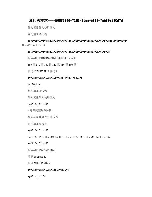
液压阀样本----500f39f6-7161-11ec-b616-7cb59b590d7d 最大流量最大使用压力阀孔加工图代码ep08-2a-01-z-04ep08-2a-01-z-05ep10-2a-01-z-05ep12-2a-01-z-05ep16-2a-01-z-05ep19-2a-01-z-05ep17-2a-01-z-05ep21-2a-01-z-05ep20-2a-01-z-05ep13-2a-01-z-05l/min30407015015040701504040l/min20350巴350巴350巴350巴350巴350巴页码12345678910页码11sv-08sv-08sv-10sv-12sv-16o19-eo17-eo21-esv-20t13a阀孔加工图代码最大流量最大使用压力ep08-2a-01-z-052通常闭型附带弹簧最大流量和最大工作压力阀孔加工图代号ep08-2a-01-z-85ep10-2a-01-z-85ep12-2a-01-z-85ep16-2a-01-z-85ep17-2a-01-z-85ep21-2a-01-z-85l/min407015015070150酒吧350350350页码121314151617sv-08sv-10sv-12sv-16o17-eo21-eep08-x-y-z-04扭矩3-4牛米例如:ep08-2a-01-n-04例如:ep08-2a-01-m-04COELEC-04w6662hex.22.2torque25-35nm3/4"-16unf-2a228最大额定压力:最大额定流量:塞孔代码:35030sv-0825-350.13巴尔/明姆克安装扭矩:重量:工作温度:内部泄漏:-40~120℃0.15cc/min(3滴/分)在最大压力350bar时25um或者更好90%额定电压滤波精度:最低电压要求:103040压力-p(巴)121086420线圈必须单独订购。
伊顿马达样本

515 [4550] 不连续
查林镶柱式(GEROLER)的 S 系列马达 具有和整体式(GEROTOR)的 H 系列低 速大扭矩马达相同的优点。在镶柱式啮合 付(GEROLER)中,精密加工过的滚子 形成了排油腔。滚子在转子转动时提供一 个滚动的支撑,从而可大大减少摩擦力, 提供高的效率,特别在低速和起动时。
190 [2750] 不连续 扭矩 Nm [lb-in] . . . . . . 440 [3905] 连续
510 [4515] 不连续
● 4 螺栓 (标准),支口直径 44,4 [1.75],安装螺孔 3/8-16,孔分布圆直径 82,6 [3.25] B.C. ● 4 螺栓 (标准),支口直径 44,4 [1.75],安装螺孔 M10 x 1,5,孔分布圆直径 82,6 [3.25] B.C. ● 2 螺栓 (标准),支口直径 101,6 [4.00],安装孔直径 14,35 [0.565],孔分布圆直径 146,0 [5.75] B.C. (SAE B) ● 4 螺栓,支口直径 82,6 [3.25],安装孔直径 13.59 [0.535],孔分布圆直径 106,2 [4.18] B.C.
50 年代后期,最原始的低速大扭矩液压 马达由一个泵的定转子元件开发出来。它 由一个内齿定子和一个相啮合的齿轮或转 子组成。有内齿的定子固定在壳体上时, 压力油引入定转子之间的空间,推动转子 围绕一个中心做摆动旋转,这种低速转动 用一个带花键的传动轴连接起来驱动输出 轴,成为查林摆线马达。
若干年后,另一种原始的摆线定转子引入 了查林摆线马达,并投入生产。这种马达 在定转子之间装入一个滚子。这种元件称 为镶柱“GEROLER”,是伊顿公司注册 的商标名称。
D661valves-(moog伺服阀样本)
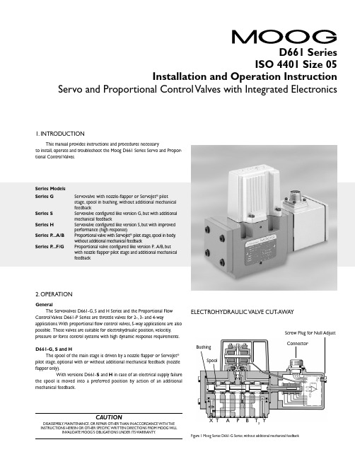
CAUTIONDISASSEMBLY, MAINTENANCE, OR REPAIR OTHER THAN IN ACCORDANCE WITH THE INSTRUCTIONS HEREIN OR OTHER SPECIFIC WRITTEN DIRECTIONS FROM MOOG WILLINVALIDATE MOOG’S OBLIGATIONS UNDER ITS WARRANTY .D661 Series ISO 4401 Size 05Installation and Operation InstructionServo and Proportional Control Valves with Integrated Electronics1. INTRODUCTIONThis manual provides instructions and procedures necessaryto install, operate and troubleshoot the Moog D661 Series Servo and Propor-tional Control Valves.2. OPERATIONGeneralThe Servovalves D661-G, S and H Series and the Proportional Flow Control Valves D661-P Series are throttle valves for 2-, 3- and 4-wayapplications. With proportional flow control valves, 5-way applications are also possible. These valves are suitable for electrohydraulic position, velocitiy,pressure or force control systems with high dynamic response requirements.D661-G, S and HThe spool of the main stage is driven by a nozzle flapper or ServoJet ®pilot stage, optional with or without additional mechanical feedback (nozzle flapper only).With versions D661-S and H in case of an electrical supply failurethe spool is moved into a preferred position by action of an additional mechanical feedback.E LE CTROHYDRAULIC VALVE CUT -AWAYFigure 1 Moog Series D661-G Series, without additional mechanical feedbackX T A P BT 2YConnectorSpoolBushingScrew Plug for Null AdjustSeries Models Series GServovalve with nozzle-flapper or ServoJet ® pilot stage, spool in bushing, without additional mechanical feedbackSeries S Servovalve configured like version G, but with additional mechanical feedbackSeries H Servovalve configured like version S, but with improved performance (high response)Series P ...A/B Proportional valve with ServoJet ® pilot stage, spool in body ,without additional mechanical feedbackSeries P ...F/GProportional valve configured like version P ...A/B, but with nozzle flapper pilot stage and additional mechanical feedbackJet pipe Annular areaNozzleReceiver2Operating Principle of the T wo-Stage ValveAn electric input signal (flow rate command) is applied to the integrated control amplifier which drives a current through the coils of the pilot stage torque motor. Thus the deflected nozzle-flapper system produces a pressure difference across the drive areas of the spool and effects its movement. The position transducer which is excited via an oscillator measures the position of the spool (actual value, position voltage).This signal is then rectified by a demodulator and is fed back to the control amplifier where it is compared with the command signal. The control amplifier drives the torque motor until command voltage and feedback voltage are equal.Thus, the position of the spool is proportional to the electric command signal.Proportional Flow Control Valve D661-...PThe nozzle flapper design of the pilot stage has been converted into an improved version with jet pipe amplifier (ServoJet ®).The ServoJet ® pilot stage consists mainly of torque motor, jet pipe and receiver.A current through the coil displaces the jet pipe from neutral. This displacement combined with the special shape of the nozzle directs a focussed fluid jet more into one receiver bore than into the other.The jet now produces a pressure difference in the control ports. This pressure difference results in a pilot flow, which in turn causes a spool displacement. The pilot stage drain is through the annular area around the nozzle to tank.Operating Principle of the T wo-Stage ValveAn electric input signal (flow rate command) is applied to the integrated control amplifier which drives a current through the coil of the pilot stage torque motor. The thus deflected jet pipe produces a pressure difference across the drive areas of the spool and effects its movement.The position transducer which is excited via an oscillator measures the position of the spool (actual value, position voltage). This signal is then demodulated and fed back to the controller where it is compared with the command signal. The controller drives the torque motor until the error between command signal and feedback signal is zero. Thus the position of the spool is proportional to the electric command signal.Failsafe Version D661-...PFor applications with proportional control valves where certain safety regulations are applicable, a defined metering spool position is needed in order to avoid potential damage. Therefore, failsafe versions are offered as an option for the MOOG proportional valves.After external triggering, this failsafe function causes a defined metering spool position.Mechanical Failsafe version (biased pilot stage with mechanical feedback)The safe position of the spool will be obtained after cut off of pilot pressure supply (external pilot connection) or operating pressure supply D661-P ...A/BWD661-P ...A/BU Proportional Valve D661-P ...A/BWand D661-P ...A/BU Series with electrically operated failsafe functionProportional Valve D661-P ...AP Serieswith electrically operated failsafe function2- stage Proportional Valve D661-...P ...A/B SeriesServovalve D661 - ...S and H Series with additional mechanical feedback3Electric characteristics of the 2/2-way solenoid valveFunctionelectro magnetic Nominal voltage 24 VDC Nominal power12 WDIN 43650-1Form A: 2+PE-PG9With failsafe versions R and L, a defined spool position is reached when the electric supply to the valve electronics is switched offwhile the pilot pressure is still applied. With version M, the resulting spool position is undefined.Electrically operated failsafe versionThe safe position of the spool will be obtained after switching off the integrated 2/2-way solenoid seat valve.With failsafe versions W , U and G, after cut-off of the solenoid, the spool moves to midposition. When the electric supply to the valveelectronics is switched off while the pilot pressure is still effective and the solenoid is still switched on, the spool will move to a defined end position with versions U and G.With failsafe version P , the integrated seat valve will shut off the external pilot pressure after switching off the solenoid.Cutting off the 24 VDC supply to the solenoid operated 2/2-way seat valveo protect relay contacts or semiconductors against damage, a Zener diode is required1)With version P at 210 bar pilot or operating pressure,with versions G ,S and H at 140 bar pilot or operating pressure,fluid viscosity of 32 mm˝/s and fluid temperature of 40°C.2)For long life wear protection of metering landsFor additional technical information such as dimensions, ordering information, etc., see the D660 series catalog.T echnical DataInternal/External Pilot Connection a.Conversion for operation with internal or external pilot connection.The pilot connection mode as shipped is indicated by the respective code letter of the type designation on the nameplate.With the 5-way version, where the T and T 2 ports are interchangedwith the P port, pilot supply port X and return portY must be connected externally.43. SAFETY INSTRUCTIONSWarnings and Symbols a.Refers to special orders and prohibitions to prevent damage b.Refers to special orders and prohibitions to prevent injury or extensive damageCorrect Application a.The D661 Series Valves are control valves suited for electrohydraulicposition, velocity, pressure and force control.b.The valves are designed for flow control in hydraulic systems thatoperate with mineral oil based fluids. Others upon ing the valves for purposes other than those mentioned above isconsidered contrary to the intended use. The user bears entirely the risk of such misuse.d.Correct application involves also observing the operating instruction andcomplying with the inspection and maintenance directives.Organizational Measures a.We recommend including this operating instruction into themaintenance plan of the machine/plant.b.In addition to the operating instruction, observe also all other generallyapplicable legal and other mandatory regulations relevant to accident prevention and environmental protection. Instruct the operator accordingly.c.All safety and danger prevention instructions of the machine/plant mustmeet the requirements of EN 982.Selection and Qualification of Personnel a.Only well-trained and instructed personnel are allowed to work with Moogcontrol valves.b.Work with electrohydraulic valves must be carried out only by personnelhaving special knowledge and experience in plants running with electrohydraulic controls.Safety Instructions for Specific Operational Phases a.T ake the necessary precautions to ensure that the machine/plant isused only when in a safe and reliable state.b.Check the machine/plant at least once per working shift for obviousdamage and defects (i.e. leakage). Report any changes to the responsible group/person immediately. If necessary, stop the machine immediately and secure it.c.In the event of malfunctions, stop the machine/plant immediately andd.If the machine/plant is completely shut down for maintenance and repairwork at the valve, it must be secured against inadvertent start up by:➢ Locking the principal control elements and removing the key.➢ Attaching a warning sign to the main switch.Safety Instructions for the Operation of Hydraulic Plantsa.Work on electrohydraulic equipment must be carried out only by personnelb.Check all lines, hoses and fittings of the plant regularly for leaks andobvious damage. Repair damage immediately.c.Before removing the valve, depressurize all system sections to beopened, pressure lines and accumulators of the hydraulic system in accordance with the specific instructions for the plant.d.When handling oil, grease and other chemical substances, observe safetyregulations valid for each product.4. INSTALLATIONGeneral Information pare model number and valve type with information from thehydraulic schematic or bill of material.b.The valve can be mounted in any direction, fixed or moving.c.Check mounting surface flatness (0.02 mm for 100 mm) andsurface finish (Ra <1 µm)d.Pay attention to cleanliness of mounting surface and surroundings wheninstalling the e lint-free tissue to clean!f.Before installation, remove shipping plate from the valve and save itfor later use.g.Pay attention to correct position of ports and location of o-rings duringe M6 x 60 socket head bolts according to DIN 912 for mounting,strength class 10.9 or 12.9, and cross torque to 13 Nm (tolerance ±10 %)Electric Null adjust(behind screw plug)Set screw 4M4 x 6Set screw 1M4 x 6Set screw 2M4 x 6Set screw 3M4 x 6X 1)P YFilterServovalve D661 Gwithout mechanical feedbackand Proportional Valve D661 P ...A/BPilot Flow Set Screw M4 x 6Supply bore 1bore 2Internal P closed open External X openclosedPilot Flow Set Screw M4 x 6Return bore 3bore 4Internal T closed open E xternal Yopenclosed b.Conversion instruction for Servovalves D661-G and Proportionalvalves D661-P ...A/B1) Check for sufficient length (100 mm) of mounting surface!...P ...A/BD661-...P 5c.Conversion instruction for Servovalves D661-S, H and P ...F/G screw plugM4 x 8 DIN 6912-8.8with metal sealring U4,5-7-1FilterElectric Nulladjust(behind screw plug)X PPilot Flow Screw Plug Supply In PortInternal P X External XP5. SETTING UPThis information is valid for new installations to be put into operation as well as for repair cases.Filling the Hydraulic SystemNew oil is never clean. Therefore, the system should generally be filled by using a filling filter .This fine mesh filter should at least complywith the following requirement: ß10 ≈ 75 (10 µm absolute).Flushing the Hydraulic SystemBefore the hydraulic system is put into operation for the first time (also after modifications), it has to be flushed carefullyaccording to the instructions of the manufacturer of the plant / machine.a.Before flushing, suitable flushing elements have to be inserted in the pressure filters instead of the high pressure elements.b.Before flushing, the operational temperature of the hydraulic system should be achieved. Observe temperature!c.A flushing plate or, if the system allows, a directional valve should be mounted in place of the Moog porportional valve. The P- and T-connections are flushed through the flushing plate. The user A- and B-Attention: The directional valve can lead to unpermissablemovements in the load (i.e. with parallel drives), which may result in damage of the plant / machine. Instructions of the manufacturer have to be strictly observed.Minimum flushing time t can be calculated as follows:d.The flushing process can be considered completed when a system cleanliness of 15/12 according to ISO 4406 or 6 according to NAS1638 or better is achieved. A long life of the metering lands of the proportional valve can be expected for this cleanliness class.V = content of reservoir [gallons]Q = flow rate of the pump [gpm]t = V • 5Qe.Replace flushing elements in the pressure filters by suitable high pressure elements after flushing. Install Moog proportional valve instead of flushing plate or directional valve.Setting Up a.Set up machine/plant according to the operation instructions of the manufacturer after the valves have been installed. Vent hydraulic system!b.The safety instructions of the machine/plant manufacturer must be observed. Especially the safety requirements for machines like injection molding machines (EN 201), blow molding machines (EN 422) and die casting machines (EN 869), to name a few, are important.c.Observe oil temperature.d.Check hydraulic system for external leakage!6. MAINTENANCEBesides regular visual inspection for external leakage and filter replacement, maintenance work at the D661 Series valves is not required.Explosion proof valves D661K... must not be opened by the customer! Unauthorized opening will invalidate the explosion proof approval! Return failed valve to the factory.Moog valves can only be repaired at Moog Service Centers (for addresses see back page of this operation instructions).Filter ReplacementThe built-in filter disk protects orifices and nozzles against coarse contaminants. W ith severe contamination, the valve response will be reduced.Replace filter!Cleaning the filter is useless and may be dangerous!Before starting to work on the valve, clean the external surface around the filter cover!Attention: The filter disk (21) flows from inside to the outside.After removal of the cover (20) any contamination particles are on the insideof the disk (21) and therefore, cannot be seen from outside.a.Remove four internal hex bolts (38) using A llen wrench (3 mm). Removecover (20). Remove the filter disk (21) now accessible by using a scriber or a fine screwdriver as extraction tool.b.(53) for damage.Replace if necessary.c.Insert o-ring (53) first. Then insert the new filter disk (21) such that the side with the notch at the rim points outward. Mount o-ring (59) on the cover (20) using clean grease, and mount cover to the valve body.T orque the four bolts (38) to 4 Nm (35 in-lb).d.Check valve for external leakage after pressurizing it.ELECTRONICS INFORMATIONValve connectorsPossible connectors Please note information regarding input signals on the nameplate!Valve electronics with supply voltage ± 15 VDC and 6+PE pole connector Number Supply Voltageof Pins ± 15 VDC 24 VDC6 + PE X X 11 + PE–X 11 + 1 (PE) Bayonet X –6 (old, without PE)X –12 (old, without PE) BayonetX–a.Command inputCommand signal 0 to ±10 VThe spool stroke of the valve is proportional to (U D – U E ). 100% valve opening P ➔ A and B ➔ T is achieved at (U D –U E ) = +10 V . At 0 V command the spool is in the center position.The input stage is a differential amplifier. If only one command signal isavailable, pin D or E is connected to signal ground (pin C) according to the required operating direction (to be done at the mating connector).Command signal 0 to ±10 mAThe spool stroke of the valve is proportional to (I D –I E ).100% valve opening P ➔A and B ➔T is achieved at (I D –I E )= +10 mA. At 0 mA command the spool is in the center position.Either pin D or E is used according to the required operating direction. T he unused pin is left open (not connected at the mating connector). The input pins D and E are inverting.b.Monitoring outputActual value 0 to ±10 VThe actual spool position value can be measured at pin F . This signal can be used for monitoring and fault detection purposes.The spool stroke range corresponds to ±10 V . +10 V corresponds to 100% valve opening P ➔ A and B ➔ T .Actual value 0 to ±10 mAThe actual spool position value can be measured at pin F . This signal can be used for monitoring and fault detection purposes.The spool stroke range corresponds to ±10 mA. +10 mA corresponds to 100% valve opening P ➔ A and B ➔ T .Connector Wiring - T ype code S (see sticker on the electronics housing)6Valve electronics with supply voltage ± 15 VDC and 11+1 pole bayonet connectorAlternate connector for certain valve models a.Command inputCommand signal 0 to ±10 VThe spool stroke of the valve is proportional to (U D – U E ). 100% valve opening P ➔ A and B ➔ T is achieved at (U D –U E ) = +10 V . At 0 V command the spool is in the center position.The input stage is a differential amplifier. If only one command signal is available, pin D or E is connected to signal ground (pin C) according to the required operating direction (to be done at the mating connector).Command signal 0 to ±10 mAThe spool stroke of the valve is proportional to (I D – I E ).100% valve opening P ➔ A and B ➔ T is achieved at (I D – I E ) = +10 mA. At 0 mA command the spool is in the center position. Either pin D or E is used according to the required operating direction. T he unused pin is left open (not connected at the mating connector). The input pins D and E are inverting.Command signal 4 to 20 mAThe spool stroke of the valve is proportional (I D –12 mA). 100% valve opeming P ➔ A and B ➔ T at I D = 20 mA. At 12mA command the spool is in the center position.The unused Pin E is left open (not connected in the mating connector).b.Monitoring outputThe actual spool position value can be measured at pin F .This signal can be used for monitoring and fault detection mand signal 0 to ±10 VThe spool stroke range corresponds to ±10 V .+10 V corresponds to 100% valve opening P ➔ A and B ➔ T .Command signal 0 to ±10 mAThe spool stroke range corresponds to ±10 mA.+10 mA corresponds to 100% valve opening P ➔ A and B ➔ T .Command signal 4 to 20 mAThe spool stroke range corresponds to 4 to 20 mA.20 mA corresponds to 100% valve opening P ➔ A and B ➔T .Please note "General Requirements" on page 6.Connector Wiring - T ype code V (see sticker on the electronics housing)7Connector Wiring - Type code 6Valve electronics with supply voltage ± 15 V DC and 6 pole connector (without protective grounding)a.Command inputCommand signal 0 to ±10 VThe spool stroke of the valve is proportional to (U D – U E ). 100% valve opening P ➔ A and B ➔ T is achieved at (U D –U E ) = +10 V . At 0 V command the spool is in the center position.The input stage is a differential amplifier. If only one command signal isavailable, pin D or E is connected to signal ground (pin C) according to the required operating direction (to be done at the mating connector).Command signal 0 to ±10 mAThe spool stroke of the valve is proportional to (I D – I E ).100% valve opening P ➔ A and B ➔ T is achieved at (I D – I E )= +10 mA. At 0 mA command the spool is in the center position.Either pin D or E is used according to the required operating direction. T he unused pin is left open (not connected at the mating connector). The input pins D and E are inverting.Command signal 4 to 20 mAThe spool stroke of the valve is proportional (I D –12 mA). 100% valve opeming P ➔ A and B ➔ T at I D = 20 mA.At 12mA command the spool is in the center position.The unused Pin E is left open (not connected in the mating connector).b.Monitoring outputThe actual spool position value can be measured at pin F.This signal can be used for monitoring and fault detection mand signal 0 to ±10 VThe spool stroke range corresponds to ±10 V .+10 V corresponds to 100% valve opening P ➔ A and B ➔ T .Command signal 0 to ±10 mAThe spool stroke range corresponds to ±10 mA.+10 mA corresponds to 100% valve opening P ➔ A and B ➔ mand signal 4 to 20 mAThe spool stroke range corresponds to 4 to 20 mA.20 mA corresponds to 100% valve opening P ➔ A and B ➔ T.8Valve electronics with supply voltage ± 15 V DC and 12 pole bayonet connector (without protective grounding)a.Command inputCommand signal 0 to ±10 VThe spool stroke of the valve is proportional to (U D – U E ). 100% valve opening P ➔ A and B ➔ T is achieved at (U D –U E ) = +10 V . At 0 V command the spool is in the center position.The input stage is a differential amplifier. If only one command signal isb.Monitoring outputThe actual spool position value can be measured at pin F .This signal can be used for monitoring and fault detection mand signal 0 to ±10 VThe spool stroke range corresponds to ±10 V .+10 V corresponds to 100% valve opening P ➔ A and B ➔ T .Command signal 0 to ±10 mA9Valve electronics with supply voltage 24 Volt and 6+PE - pole connector a.Command inputCommand signal 0 to ±10 VThe spool stroke of the valve is proportional to (U D – U E ). 100% valve opening P ➔ A and B ➔ T is achieved at (U D –U E ) = +10 V.At 0 V command the spool is in the center position.The input stage is a differential amplifier. If only one command signal is available, pin D or E is connected to signal ground (pin B) according to the required operating direction (to be done at the mating connector).Command signal 0 to ±10 mAThe spool stroke of the valve is proportional to (I D – I E ). 100% valve opening P ➔ A and B ➔ T is achieved at (I D – I E ) = +10 mA. At 0 mA command the spool is in the center position.Either pin D or E is used according to the required operating direction.The unused pin is left open (not connected at the mating connector).The input pins D and E are inverting.b.Monitoring outputActual value +2,5 to +13,5 VValves with voltage and current command inputThe actual spool position value can be measured at pin F (see diagram below). This signal can be used for monitoring and fault detection purposes.The spool stroke range corresponds to +2,5 to +13,5 V . The center position is at +8 V . +13,5 V corresponds to 100% valve opening P ➔ A and B ➔ T.10Valve electronics with supply voltage 24 V olt and 11+PE - pole connector a.Command inputCommand signal 0 to ±10 VThe spool stroke of the valve is proportional to (U D – U E ). 100% valve opening P ➔ A and B ➔ T is achieved at (U D –U E ) = +10 V . At 0 V command the spool is in the center position.The input stage is a differential amplifier. If only one command signal isavailable, pin D or E is connected to signal ground (pin B) according to the required operating direction (to be done at the mating connector).Command signal 0 to ±10 mAThe spool stroke of the valve is proportional to (I D – I E ). 100% valve opening P ➔A and B ➔ T is achieved at (I D – I E ) = +10 mA. At 0 mA command the spool is in the center position.Either pin D or E is used according to the required operating direction.The unused pin is left open (not connected at the mating connector). The input pins D and E are inverting.b.Monitoring outputActual value 0 to ±10 VValves with voltage and current command inputThe actual value, i. e. the spool position, can be measured between pins 6 and 7. This signal can be used for monitoring and fault detection purposes. The signal can only be measured using a weighted differential amplifier (see dia-gram below) or a voltmeter with an input impedance greater than 1M Ω. T he spool stroke range corresponds to ±10 V . The centered position is at 0 V .+10 V corresponds to 100% valve opening P ➔ A and B ➔ T .If the actual value will be used with a machine control system, the differential input circuit must be used. Another option is to use the aforementioned circuit for the 6+PE pole connector. Pin 6 according to DIN 43 651corresponds to pin F according to DIN 43 563 (see diagram page 12).Circuit diagram for measurement of actual value U 6-7 (position of main spool) for valves with 11+PE pole connectorConnector Wiring - Type code letter E (see sticker on the electronics housing)Please note "General Requirements" on page 10.118. TOOLS AND EQUIPMENTa.5mm Allen wrenchb.3mm Allen wrenchrge blade screwdriverd.Small screwdrivere.Scriber or small screwdriverf.Clean grease (mounting and insertion of O-rings)The D661 Series valves require tools for installation, set up, null adjustment and filter replacement.➢ Installation of the valve➢ Mounting of the D661 Series requires 5mm Allen wrench ➢ Null adjust of the valve at set up➢ Large blade screwdriver to remove the cover screw(see cut-away diagram on page 1)➢ Small screwdriver for zero setting on internal potentiometerReplacement PartsPart Description D661-Qty.Part Number O-Ring, ports P , T , A, B, (T 2)all 542082-004O-Ring, ports X&Y all 242082-011Replaceable Filter Disk P ...A/B 1A67999 200Replaceable Filter Disk G, S, H & P ...F/G 1A67999 100O-Ring, behind filter disk all 1A25163 013 015O-Ring, for filter cover P ...A/B1B97009 080O-Ring, for filter coverG, S, H 1A25163 017 020Allen Setscrew, ports X & Y G & P 266166 040 006Screw plug, port X S & H 166098 040 006Seal, port X S & H1A25528 040Accessories (not part of the valve delivery)Part DescriptionD661-Qty.Part NumberMating Connector ,waterproof, protection IP65 6+PE-pole DIN 43563B97007 061 11+PE-poleDIN 43651B97024 111 11+1-pole (Bayonet)MIL C-26482/14-12B97027 012 6-poleMIL C-5015/14S-6A26201 004 12-pole (Bayonet)MIL C-26482/14-12B97027 012Mounting Manifolds See special data sheet Mounting BoltsM6x60 DIN 912-10.9...G and ...P 4A03665-060-060 M6x55 DIN 912-10.9...H and ...S4A03665-060-055Flushing PlateB67728-001Flushing Plate B67728-002Flushing PlateB67728-003127. ELECTRICAL NULL ADJUSTMENTThe hydraulic null of the valve is preset at the factory with a tolerance of ± 2% of rated signal. If necessary, this null can be readjusted by the user of the valve.a.null! Contact machine/plant manufacturer.b.Procedure: Remove the command signal to the valve only by disconnecting command signal lead at the cabinet.Remove cover screw on electronics housing to access the null adjust potentiometer. Use a small screwdriver (blade width 2.5 mm) to turn the potentiometer screw either clockwise or counterclockwise. Usually it will not be necessary to turn the screw more than 2 turns in either direction (± 1 turn is equivalent to ± 15% null shift).c.While adjusting, watch the actuator (motor) motion to find the null position. With overlapped valves, turn the null adjust screw carefully in both directions to just start motion and then back into deadzone midposition between those two screw positions.d.After proper null adjustment, reconnect the command signal lead and install protective cover screw again.。
609伺服阀样本
609伺服阀样本(原创实用版)目录1.介绍 609 伺服阀2.609 伺服阀的特点和优势3.609 伺服阀的应用领域4.609 伺服阀的样本内容正文一、介绍 609 伺服阀609 伺服阀是一种采用微处理器控制,具有高精度、高速度、高可靠性等特点的液压控制元件。
它主要用于各类工业控制设备,如注塑机、液压机床、自动化生产线等,实现对液压系统的精确控制。
二、609 伺服阀的特点和优势1.高精度:609 伺服阀采用闭环控制,能够实现对液压系统的高精度控制,提高了设备的运动精度。
2.高速度:609 伺服阀的响应速度快,能够实现液压系统的快速启停和调节,提高了设备的工作效率。
3.高可靠性:609 伺服阀采用微处理器控制,具有自诊断功能,能够对故障进行及时检测和报警,提高了设备的稳定性和可靠性。
4.良好的节能效果:609 伺服阀能够在液压系统中实现软启动和软停止,减少了系统的冲击和压力波动,降低了能源损耗。
三、609 伺服阀的应用领域1.注塑机:609 伺服阀可以用于控制注塑机的液压系统,实现注射速度、压力、位置等的精确控制。
2.液压机床:609 伺服阀可以用于控制液压机床的各个动作,如刀具的快速移动、换刀等,提高机床的加工精度和效率。
3.自动化生产线:609 伺服阀可以用于控制自动化生产线上的各种设备,如输送带、搬运机器人等,实现生产线的高效稳定运行。
四、609 伺服阀的样本内容609 伺服阀的样本通常包括以下几个部分:1.产品图片:包括 609 伺服阀的外观、结构等图片,以便用户了解产品的外观特征。
2.产品参数:包括 609 伺服阀的尺寸、重量、工作电压、工作电流等技术参数,方便用户了解产品的性能指标。
3.工作原理:介绍 609 伺服阀的控制原理和使用方法,帮助用户正确操作和使用产品。
4.应用案例:列举 609 伺服阀在不同领域的应用案例,展示产品的实际应用效果。
美国穆格型号
美国MOOG电液伺服阀穆格电液伺服阀 MOOG伺服阀穆格伺服阀穆格MOOG三级伺服阀MOOG直动式伺服阀D634-319C D634-399C D634-1003 D634-1005 D634-1007 D634-1008 D634-514A D634-557 D634-394CD634-1009 D634-1010 D634-1011 D634-1012 D634-1013 D634-1014 D634-1015 D634-1016 D634-1018D634-1019 D634-1023 D634-1024 D634-1025 D634-1026 D634-1027 D634-1028 D634-1029 D634-1031D634-1032 D634-1033 D634-1034 D634-1035 D634-1036 D634-1037 D634-1040 D634-1041 D634-1042D634-1043 D634-1045 D634-1046 D634-1047 D634-1049 D634-1050 D634-1051 D634-1052 D634-1053D634-1054 D634-1055 D634-1056 D634-1057 D634-1058 D634-1059 D634-1060 D634-3001 D634-301CD634-305C D634-307C D634-308C D634-317C D634-318C D634-322C D634-324C D634-326C D634-384CD634-327C D634-330C D634-331C D634-335C D634-341C D634-345C D634-346C D634-358C D634-361CD634-362C D634-368C D634-371C D634-372C D634-373C D634-374C D634-381C D634-383C D633Z7397D634-385C D634-386C D634-387C D634-388C D634-389C D634-390C D634-391C D634-392C D633Z7383D634-396C D634-397C D634-398C D634-400C D634-402C D634-403C D634-404C D634-405C D634-1001D634-406 D634-501A D634-502A D634-503 D634-504 D634-508 D634-511 D634-512A D634-513 D634-515 D634-516A D634-517 D634-518A D634-520A D634-521 D634-524A D634-525AD634-526D634-527A D634-528A D634-529A D634-530A D634-531 D634-532 D634-533 D634-534D634-536AD634-537A D634-538A D634-539 D634-540A D634-541 D634-542A D634-543A D634-544AD634-545D634-546A D634-547 D634-548 D634-550 D634-551 D634-552 D634-553A D634-554A D634-555 D634-558 D634-559 D634-560 D634K2000C D634K2001C D634K2002C D634K2003C D634K2004C D634K2005C D634K2006C D634K2007C D634K2008C D634K2009C D634K2010C D634K2011CD634K2012C D634K2013CD634K2014C D634K2015C D634K2016C D634K2017C D634K2018C D634K2019C D634K2020D634Z1020D634Z1021 D634Z1022 D634Z1038 D634Z1044 D634Z314C D634Z351C D634Z359CY D634Z360CD634Z360CYD634Z380C D634Z395C D634Z505A D634Z509 D634Z510 D634Z549A D633E703 D633E704D633E713AD633E714A D633E7365 D633E7366 D633E7411 D633K2000B D633K2001B D633K2002BD633K2003BD633K2005B D633K2006B D633K2007B D633K2008B D633K2009B D633K2010B D633K2011BD633K2012BD633K2013B D633K2014B D633K2015B D633K2017B D633K2018B D633K2019B D633K2020BD633K2021BD633K2022B D633K2023B D633K2024B D633K2025B D633K2026B D633K2027B D633K2028BD633K2029BD633K2030B D633K2031B D633K2032B D633K2033B D633K2034B D633K2035B D633K2036BD633K2037BD633K2038B D633K2039B D633K2040B D633K2041B D633K2042B D633K2043B D633K2044BD633K2045BD633K2046B D633K2047B D633K2048B D633K2049 D633K2050 D633K2051 D633Z303B D633Z305B D633Z313BD633Z317B D633Z338B D633Z348B D633Z371B D633Z379B D633Z480B D633Z506B D633Z528B D633Z529BD633Z532B D633Z539B D633Z557B D633Z570B D633Z585B D633Z586B D633Z587B D633Z588B D633Z589BD633Z590B D633Z7309 D633Z7324 D633Z7337 D633Z7352 D633Z7353 D633Z7361 B67728-001 B67728-002B67728-003 A03665-060美国Moog伺服阀说明:美国Moog伺服阀MOOG穆格伺服阀D633,D634系列,G761-3005,G761-3004,G761-3003,G761-3002,G761-3001,J761,J072,J869,G631 G761系列伺服阀 D791三级伺服阀 D661电反馈式伺服 72系列机械反馈伺服 D633/D634直动式伺服阀功率级阀型号/先导级 MOOG机能代号 D661-4651/ C41156-421 G35JOAA6VSX2HA D661-4652/ C4 1156-421 G15JOAA6VSX2HA D661-4636/C41156-421 G60KOAA5VSX2HA D661-4469C/C41156-421 G75KOAA6VS X2HA D661-4697C/C41156-421 G15JOAA5VSX2HA D661-4033/ C41156-421 P80HAAF6VSX2-A D661-4059/C41 156-411 P80HAAF6VSX2-B D661-4444C/C41156-421 G60JOAA6VSX2HA D661-4443C/C41156-421 G45J0AA6VS X2HA D661-4506C/C41156-421 G23J0AA6VSX2HA D661-4539C/C41156-421 G35JOAA5VSX2HA MOOG型号/先导级 MOOG机能代号 D662Z4311K/D630-072A P01JXMF6VSX2-A D662-4010/D061-8411 D02HABF6VSX2-A D662Z 4336K/D630-272D P01JXMF6VSX2-A MOOG型号/先导级 MOOG机能代号 D663Z4307K/D630Z067A P02JONF6VS X2-A D663-4007/D061-8412 L03HABD6VSX2-A MOOG型号/先导级 MOOG机能代号 D663Z4307K/D630Z067A P 02JONF6VSX2-A D663-4007/D061-8412 L03HABD6VSX2-A D634-341C R40K02M0NSS2 D634-319C R40KO2M0NS P2 D633-333B R16KO1F0NSS MOOG型号/先导级 MOOG机能代号 D791-5009/D761-2612 S16J0QA6VSB0-P D7 91-4025/ S25J0PA6VSX2-A D791-4001/待查 S25J0QB6VSX2-B D791-4002/D761-2617 S25J0QB5VSX2-B D791-4028/D761-2619 S25J0QB6VSX2-B D791-4046/D761-2619 S25J0QA6VSX2-B MOOG型号 MOOG机能代号 07 2-559A S15F0FA4VBL, 072-558A S22FOFA4VBL《新型号:072-1203-10》。
伺服阀样本

Australia Melbourne Austria Vienna Brazil São Paulo China Shanghai Denmark Birkerød England Tewkesbury Finland Espoo France Rungis Germany BöblingenHong Kong Kwai Chung India Bangalore Ireland Ringaskiddy Italy Malnate Japan Hiratsuka Korea Kwangju Philippines Baguio Russia Pavlovo Singapore Singapore Spain Orio Sweden Göteborg USA East Aurora (NY)B A M /W A /2000 P r i n t e d i n G e r m a n yD691 EN / Rev1 / 09.97MOOG Controls Limited Ashchurch Tewkesbury Gloucestershire GL20 8NATelephone (01684) 29 66 00Telefax (01684) 29 67 60MOOG GmbHHanns-Klemm-Straße 28D - 71034 Böblingen Postfach 1670D - 71006 Böblingen Telefon (07031) 622-0Telefax (07031) 622-19111D691 SeriesOrdering informationModel-Number Type designationPreferred configurations are highlighted.All combinations may not be available.SV*=Solenoid valve VE**=Valve electronicsOptions may increase price.Technical changes are reserved.D691 SeriesTechnical data= 210 bar pilot or operating pressure, respectively, fluid viscosity of 32 mm2/s and fluid temperature of 40 °C.1) measured at px109D691 SeriesFail-safe versionThe mounting manifold must conform to ISO 4401-05-05-0-94. (see page 8)Connector wiring DIN 43650-1Form A: 2+PE - PG9Block diagramsElectrical characteristicsof the 2/2-way poppet valve for the electrical fail-safe version.Nominal voltage U N 24 VDC Nominal power P N29 WHydraulically activated valves for the fail-safe version on request.Note:Detailed informations about safety requirements according to EN 954-1 see MOOG Appli-cation Note AM 391 E.Spring centred version (installation drawing see page 8)Version with poppet valve and spring centringFunctionFor applications with proportio-nal control PQ-Valves where certain safety regulations are applicable, a defined metering spool position is needed in order to avoid potential damage.Therefore a fail-safe version is offered as an option for the pro-portional control PQ-Valves.After external triggering this fail-safe function causes a defined metering spool position: over-lapped or underlapped middle position.In order to move the spool to the safe position the two control chambers of the main stage are hydraulically short circuited via a 2/2-way poppet valve. The spring force moves the spool into the defined metering spoolposition.8D691 SeriesInstallation drawing Spare parts, Accessories2nd return port T 2 must be used.With 5-way version the P and T ports are interchanged, i.e. T changes to P , T 2 changes to P 2and P changes to T.than 1µm.7Command signal for pressure p Voltage command 0 to +10 V The controlled load pressure is proportional to (U 9 – U 3). 100 %rated pressure is achieved at +10V input signal.Current command 0 to +10 mA (4 to 20 mA resp.)The controlled load pressure is proportional to I 9. 100% rated pressure is achived at +10 mA (20 mA resp.) input signal.Actual value spool position (Q)Signal levels for actual flow output (U 6 – U 3 and I 6 resp.) are given in the wiring table below.Actual value pressure pSignal levels for actual pressure output (U 10 – U 3 and I 10 resp.) are given in the wiring table below.Note: When the p -potentiome-ter is readjusted with reference to a manometer this output will not change.Wiring for valves with 11+PE pole connectorto DIN 43 651 and mating connector (metal shell) with leading protective grounding connection ()D691 SeriesValve electronics with supply voltage ±15 VoltCommand signal for flow Q Voltage command 0 to ±10 V The spool stroke of the valve is proportional to (U 4 – U 3). 100 %valve opening P ç A und B ç T is achieved at +10 V input signal.At 0 V command the spool is in a centred position.Current command 0 to ±10 mA (4 to 20 mA resp.)The spool stroke of the valve is proportional to I 4 (I 4 – 12 mA resp.). 100 % valve opening P ç A and B ç T is achieved at +10 mA (20 mA resp.) input signal. At 0 mA (12 mA resp.) command the spool is in a centred position.6D691 SeriesValve electronics with supply voltage 24 VoltCommand signal for flow Q Voltage command 0 to ±10 V The spool stroke of the valve is proportional to (U 4 – U 2). 100 %valve opening P ç A und B ç T is achieved at +10 V input signal. At 0 V command the spool is in a centred position.Current command 0 to ±10 mA (4 to 20 mA resp.)The spool stroke of the valve is proportional to I 4 (I 4-12 mA resp.).100 % valve opening P ç A and B ç T is achieved at +10 mA (20 mA resp.) input signal. At 0 mA (12 mA resp.) command the spool is in a centred position.Actual value spool position (Q)Valves with voltage and current command inputThe actual value, i. e. the spool position, can be measured be-tween pins 6 and 7. This signal can be used for monitoring and fault detection purposes. The signal must be measured with a voltmeter having an input im-pedance greater than 1 M W (dia-gram below, left). The spool stroke range corresponds to ±10 V. The centred position is at 0 V. +10 V corresponds to 100 %valve opening P ç A.If the actual value shall be usedwith a machine control system the differential input circuit must be applied (diagram below,right).Actual value pressure pSignal levels for actual pressure output (U 10 – U 2 and I 10 resp.) are given in the wiring table beloow.Note: When the p -potentiome-ter is readjusted with reference to a manometer this output will not change.Wiring for valves with 11+PE pole connectorto DIN 43 651 and mating connector (metal shell) with leading protective grounding connection ()Command signal for pressure p Voltage command 0 to +10 V The controlled load pressure is proportional to (U 9 – U 2). 100 %rated pressure is achieved at +10 V input signal.Current command 0 to +10 mA (4 to 20 mA resp.)The controlled load pressure is proportional to I 9. 100 % rated pressure is achieved at +10 mA (20 mA resp.) input signal.5D691 SeriesApplication notes3-way valve in main line 5-way valve in main line 4-way valve in main line2x2-way valve in by-pass line (bleed off)The device operates as a 3-way pressure reducing valve with flow from P ç A or A ç T. Only one load port (A) is used.The device operates like the 3-way PQ-Valve but with doubled flow rate into the load. A directional change of the load motion requires an external force.Without shuttle valve.The device operates from P ç A like a 3-way PQ-Valve. In the opposite direction P ç B it allows only flow modulation. By this means the direction of load motion can be reversed (open loop velocity control for load retract).Venting of pressure transducer Before first operation of the valve the internal lines of the pressure transducer must be carefully vented.When selecting the installation position of the valve care must be taken that the bleeding screw can become effective.If the load is located higher than the PQ-Valve the load also must be vented at its highest point.Caution: Vent only at reduced pressure! Danger of injury!With shuttle valve.The device operates as an electrically adjustable 4-way throttle valve, i. e. the load can be operated with pressure control in both directions of motion.Only one of the load ports is pressure controlled. The shuttle valve transmits the driving (higher) load pressure to the single pressure transducer. An electronic logic circuit provides for the coordination of motion direction and pressure control depending on the polarity of the flow rate command signal. The other port is more or less open to tank line which is provided by the special spool land location.The spring centered fail-safe version requires external pilot supply port X to be used.The device has parallel flow pathes and operates as elec-trically adjustable pressure relief valve from A ç T and B çT 2, res-pectively. At zero command signal the valve is fully open,i. e. the pressure in the load ports is zero apart from minor pres-sure build up due to line losses. A minimum pilot pressure (p X > 15 bar) has to be secured.This can be achieved by a check valve with 15 bar cracking pressure (as shown) or by a separate pilot supply pump.D691 SeriesTypical characteristic curvesFlow and pressure responseFlow step responseFrequency response (flow)Pressure step responseExamples for pressure step response showthe effect of valve flow setting and entrap-ped fluid volume on pressure controldynamics. Valve type D691-...Q30 KB... withoptimized PID pressure limiting controllerat operating pressure pP = 250 bar.Optimised and measured with entrapped fluid volumeof 1000 cm³.Valve flow command 80 % of rated.Frequency response data measured at 140 bar pilotpressure, fluid viscosity of 32 mm²/s and fluidtemperature of 40 °C.Flow vs. signal curveat D pN = 5 bar per landSpool B:~critical lap, linear characteristic Spool U:~critical lap, curvilinear characteristic (5-way only)Spool T:~20 % overlap, linear characteristic Optimised and measured with entrapped fluid volume of 1000 cm³.Valve flow command 10 / 25 / 80 % of rated.Optimised for entrapped fluid volume of 1000 cm³ but measured with 5000 cm3.Valve flow command 80 % of rated.Optimised and measured with entrapped fluid volume of 5000 cm³.Valve flow command 80 % of rated.Note: It is necessary to adapt the valvep-electronics to the load conditions for anynew application. If required please contactMOOG for assistance.43Flow rate and pressure dropThe actual flow is dependent upon electrical command signal and valve pressure drop. The flow for a given valve pressure drop can be calculated using the square root function for sharp edged orifices as follows:Flow rate mode An electrical command signal (flow rate set point) is applied to the integrated position controller which drives the valve coil. The position transducer (LVDT) which is excited via an oscillator measures the position of the spool (actual value, position voltage).This signal is then demodulated and fed back to the controller where it is compared with the command signal. The controller drives the pilot valve until the error between command signal and feedback signal is zero. Thus the position of the spool is pro-portional to the electrical com-mand signal.Q [l/min]=calculated flow Q N [l/min]=rated flowD p [bar]=actual valve pressuredropD p N [bar]=rated valve pressuredropQ Q p p NN=∆∆Pressure control mode The afore mentioned flow rate control is superimposed with a pressure limiting control. Both command signals (external flow command signal and limiting pressure command signal) must always be present.The difference between external flow command signal and output signal of the pressure limiting controller results in a spool position command signal. This output signal is zero as long as the actual pressure is smaller than the limiting pressure command value.If the actual pressure value exceeds the limiting pressure command value, the pressure limiting controller reduces the spool position command signal until the actual pressure value equals the limiting pressure command value.If instead of pressure limiting a pressure control has to be installed, the external flow command signal must be selected that high, so that the limiting function actually occurs.This is necessary because the pressure limiting controller can only reduce the spool position command. The external flow command signal should be larger than 30 % of rated signal (see diagrams on page 4).External pilot pressure If large flow rates with high valve pressure drop are required an appropriate higher pilot pressure has to be chosen to overcome the flow forces. An approximate value can be calculated as follows:Q [l/min]=max. flowD p [bar]=valve pressure dropwith Q A K [cm 2]=spool drive area p X [bar]=pilot pressure The pilot pressure p X has to be at least 15 bar above the return pressure of the pilot stage.p QA p X K≥⋅⋅⋅−17102,∆2D691 SeriesProportional Control PQ-ValvesTwo stage withThis catalogue is for users with technical knowledge. To ensure that all necessary characteristics for function and safety of the system are given, the user has tocheck the suitability of the products described here.In case of doubt please contact MOOG.Our quality management system is certified in accordance with DIN EN ISO 9001.2-stageProportional PQ-Valve D691 Seriesthe pilot stage internal leakage flow) contributes to energysaving, especially for machines with multiple valves.Improved dynamics due to high natural frequency.(500 Hz) of the ServoJet pilot stage.Reliable operation. The high pressure recovery of the ServoJet stage (more than 80 % D p at 100 % command signal) provides higher spool driving forces and ensures enhanced spool position The proportional control PQ-Valves D691 Series are dual function valves for 2x2-, 3-, 4- and 5-way applications.The PQ-Valves modulate a fluid flow and control in closed loop a pressure (upper or lower pressure limit). The valves are suitable for pressure control and pressure limiting applications.The control electronics for the spool position and pressure loopsand a pressure transducer are integrated in the valve.For over 15 years MOOG has built PQ-Valves with integrated electronics. During this time more than 30 000 PQ-Valves have been delivered and successfully applied to injection molding, heavy industry, presses and paper processing. The val-ves have proved to be reliable especially when high dynamic performance is required.The valves have been continually developed. With MOOG ’s new ServoJet pilot stage a further step has been taken in the direction of energy saving and robustness.This pilot stage uses the jet pipe principle which for over 8 years has been operating reliably in different MOOG valves.The integrated valve electronics require either 24 Volt DC or a ± 15 Volt DC power supply.The valve series described in this catalogue have suc-cessfully passed EMC tests required by EC Directive. Please take notice of the respective references in the electronics section.X T A P B T 2 YPQ-Proportional Valves with integrated Electronics D691 SeriesISO 4401 Size 05。
中航工业南京机电液压工程研究中心_原中国航空工业第六零九研究所_

不对称度(%)
Unsymmetry(%)
≤±10
压力增益 /(%ps/1%In) 内漏/L·min-1
Pressure Gain /(%ps/1%In) Internal Leakage /L·min-1
>30 ≤3
零偏(%)
Null Bias (%)
供油压力零漂 (80%~110% ps)(%) 回油压力零漂 (0~20% ps)(%) 温度零漂 (每变化 56℃)(%) 频
(1) 耐高压、高温的密封材料及 结构
目前液压系统形成了 3 个温度 级别:Ⅰ级 为 - 5 4~71 ℃,Ⅱ级为 - 54~135℃,Ⅲ级为 -54~198℃,而 军用飞机液压系统的最高热点温度达 到了 315℃,目前 609所的液压系统电 液伺服阀设计准则都是以Ⅱ级温度范 围为准。随着压力和功率的提高,液压 系统的温度也不断提高。而有些液压 系统如发动机燃油系统温度则是按 - 55~215℃作为设计准则。密封结构和 密封元件是整个液压系统中最薄弱的 环节,因此,解决耐高压、耐高温环境 的密封结构、材料是发展电液伺服阀 的关键技术之一。
应用领域
偏转板射流式电液伺服阀的压力恢复系数和流量恢复系数 高,一般均在 70%以上,有时可达 90%以上,由于其效率较高, 既可以作前置放大元件,也可作小功率伺服系统的功率放大元件。 可以应用于燃油调节系统和舵机控制系统中。在很多场合可代替 喷嘴挡板阀。
同类产品 FF-129,FF-134 射流管式电液伺服阀
额定供油压力 ps/MPa
Rated Supply Pressure ps/MPa
21
额定流量 Qn/L·min-1
Rated Flow Qn/L·min-1
25
额定电流 In/mA
伺服阀使用说明书
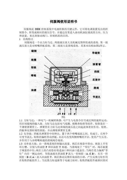
伺服阀使用说明书伺服阀是DEH控制系统中电液转换的关键元件,它可将电调装置发出的控制指令,转变成相应的液压信号,并通过改变进入油动机油缸液流的方向、压力和流量,来达到驱动阀门、控制机组的目的。
1 结构特点伺服阀是一个由力矩马达、两级液压放大及机械反馈所组成的系统。
第一级液压放大是双喷嘴挡板系统;第二级放大是滑阀系统。
其基本结构如图1所示。
图11.1 力矩马达:一种电气—机械转换器,可产生与电指令信号成比例的旋转运动,用在伺服阀的输入级。
力矩马达包括电气线圈、极靴和衔铁等组件。
衔铁装在一个薄壁弹簧管上,弹簧管在力矩马达和阀的液压段之间起流体密封作用。
衔铁、挡板和反馈杆刚性固接,并由薄壁弹簧管支撑。
1.2 先导级:挡板从弹簧管中间伸出,置于两个喷嘴端面之间,形成左、右两个可变节流孔。
衔铁的偏转带动挡板,从而可改变两侧喷嘴的开启,使其产生压差,并作用于与该喷嘴相通的滑阀阀芯端部。
1.3 功率放大级:由一滑阀系统控制输出流量。
阀芯在阀套中滑动,阀套上开有环行槽,分别与供油腔P和回油腔T相通。
当滑阀处于“零位”时,阀芯被置于阀套的中位;阀芯上的凸肩恰好将进油口和回油口遮盖住。
当阀芯受力偏离“零位”向任一侧运动时,导致油液从供油腔P流入一控制腔(A或B),从另一控制腔(B或A)流入回油腔T。
阀芯推动反馈杆端部的小球,产生反馈力矩作用在衔铁挡板组件上。
当反馈力矩逐渐等于电磁力矩时,衔铁挡板组件被移回到对中的位置。
于是,阀芯停留在某一位置。
在该位置上,反馈力矩等于输入控制电流产生的电磁力矩,因此,阀芯位置与输入控制电流的大小成正比。
1.4 特点:●衔铁及挡板均工作在中立位置附近,线性好●喷嘴挡板级输出驱动力大●阀芯基本处于浮动状态,不易卡住●阀的性能不受伺服阀中间参数的影响,阀的性能稳定,抗干扰能力强,零点漂移小2 工作原理:当力矩马达没有电信号输入时,衔铁位于极靴气隙中间,平衡永久磁铁的磁性力。
当有欲使调节阀动作的电气信号由伺服放大器输入时,力矩马达的线圈中有电流通过,产生一磁场,在磁场作用下,产生偏转力矩,使衔铁旋转,同时带动与之相连的挡板转动,此挡板伸到两个喷嘴中间。
第八次课电液伺服阀的性能参数ppt课件
静态特性
负载流量特性 空载流量特性
压力特性 静态流量特性
动态特性
频率响应 传递函数 阶跃响应
可通过特性方程、特性曲线和阀系数三种方法来表示。
篮球比赛是根据运动队在规定的比赛 时间里 得分多 少来决 定胜负 的,因 此,篮 球比赛 的计时 计分系 统是一 种得分 类型的 系统
篮球比赛是根据运动队在规定的比赛 时间里 得分多 少来决 定胜负 的,因 此,篮 球比赛 的计时 计分系 统是一 种得分 类型的 系统
由流量曲线和 名义流量曲线 就可以得到阀 的额定电流和 额定流量值。
输出流量与输入电 流呈回环状的函数 曲线
流量曲线
名义流量曲线
流量曲线的中点轨迹;当 滞 环很小时,也可以把流量曲 线的一侧看作是名义流量曲 线。
不对称度
两个极性名义流量增益 的不一致程度,通常小 于10%。
篮球比赛是根据运动队在规定的比赛 时间里 得分多 少来决 定胜负 的,因 此,篮 球比赛 的计时 计分系 统是一 种得分 类型的 系统
非线性度:
定义:表示流量曲线的不直线性。 意义:它是名义流量曲线与名义流量增益曲 线最大偏差电流偏差,以额定电流的百分比表 示) 非线性度通常小于7.5%。
篮球比赛是根据运动队在规定的比赛 时间里 得分多 少来决 定胜负 的,因 此,篮 球比赛 的计时 计分系 统是一 种得分 类型的 系统
伺服阀的动态特性
在伺服阀中,阀芯由闭环反馈来定位。 喷嘴挡板式伺服阀的反馈信号是由作用于挡板和 弹簧组件上的阀芯位移用机械方法提供的,挡板起 着将来自衔铁的输入信号与来自阀芯位移的反馈信 号进行比较的作用。 伺服阀本身就是一个闭环位置控制系统,可以用 它对阶跃输入的响应或对正弦变化输入的响应(频 率响应)以及传递函数来评定阀的动态特性。
609伺服阀样本
609伺服阀样本摘要:一、前言二、609伺服阀的简介1.什么是609伺服阀2.609伺服阀的功能与特点三、609伺服阀的应用领域1.工业控制2.自动化设备3.能源行业四、609伺服阀的性能与技术参数1.工作原理2.性能指标3.技术参数五、609伺服阀的选型与使用注意事项1.选型原则2.使用注意事项六、结论正文:一、前言随着科技的不断发展,伺服阀在工业领域的应用越来越广泛。
其中,609伺服阀作为一款具有高性能、高可靠性的产品,备受市场关注。
本文将对609伺服阀进行详细介绍。
二、609伺服阀的简介1.什么是609伺服阀609伺服阀是一种采用电子控制技术的流量控制阀门,主要用于精确控制流体的流量、压力和方向。
它具有响应速度快、精度高、可靠性好等特点,可满足各种工业过程的自动化控制需求。
2.609伺服阀的功能与特点(1)功能609伺服阀主要功能包括对流体的流量、压力和方向进行精确控制。
(2)特点a.高精度:609伺服阀采用先进的电子控制技术,能够实现高精度的流量控制。
b.快速响应:609伺服阀具有较快的响应速度,能够满足实时控制系统的要求。
c.高可靠性:609伺服阀采用先进的制造工艺,具有良好的抗干扰性能和稳定性,使用寿命长。
三、609伺服阀的应用领域1.工业控制609伺服阀广泛应用于工业自动化控制领域,如流程工业、石油化工、冶金、制药等。
2.自动化设备609伺服阀在自动化设备中也具有广泛应用,如数控机床、机器人、物流传输系统等。
3.能源行业在能源行业中,609伺服阀可用于风力发电、水力发电等新能源领域的控制系统中。
四、609伺服阀的性能与技术参数1.工作原理609伺服阀的工作原理主要是通过电子驱动装置驱动阀芯运动,实现对流体的控制。
2.性能指标(1)流量控制精度:±0.5%(2)压力控制范围:0-100 bar(3)工作温度:-20℃~+80℃3.技术参数(1)电源:DC24V(2)信号输入:4-20mA或0-10V(3)输出信号:4-20mA或0-10V五、609伺服阀的选型与使用注意事项1.选型原则在选择609伺服阀时,应根据实际应用需求,结合产品性能参数进行选型。
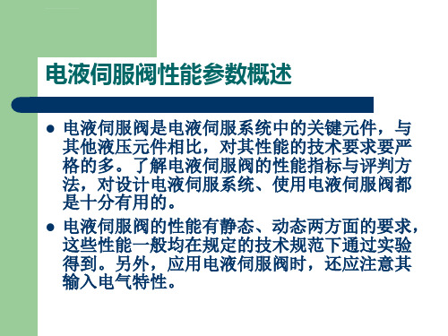
伺服阀的特性及性能参数(精)
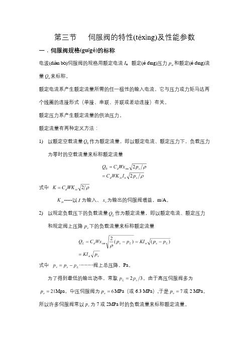
第三节伺服阀的特性(tèxìng)及性能参数一.伺服阀规格(guīgé)的标称电波(diàn bō)伺服阀的规格用额定电流I n额定(é dìng)压力和额定(é dìng)流量来标称。
额定电流系产生额定流量所需的任一极性的输入电流,它与压力或力矩马达两个线圈的连接形式(单接、串联、并联或差动连接)有关。
额定压力系产生额定流量的供油压力。
额定流量有两种定义方法:1)以额定空载流量作为额定流量,即以额定电流、额定压力下,负载压力为零时的空载流量来标称额定流量式中-----以为输入、为输出的伺服阀增益,m/A。
2)以规定负载压下的负载流量作为额定流量,即以额定电流、额定压力和规定阀上压降下的负载流量来标称额定流量式中…………阀上总压降,Pa。
为了得到最低的输出功率,常取。
由于高压伺服阀多为Mpa,中压伺服阀为MPa(或6.3 MPa),于是或2 MPa。
p为7或2MPa时的负载流量来标称额定流量。
所以许多伺服阀常以v对于四通阀来说,单个阀口的压降为阀上压降的一半,因此也有一些中压伺服阀以规定阀口压降p∆=1MPa时的负载流量来标称额定流量。
可见,不能笼统地谈额定流量,一定要明确是哪种定义及条件下的额定流量。
选用或代用伺服阀时尤其要注意这一点。
〔实例(shílì)〕某引进设备的钢带自动跑偏控制系统,实际油源压力4.5MPa,采用阀口引进pQ=20L/min的伺服阀。
∆=1MPa时负载(fùzài)流量L现要改用额定(é dìng)压力 MPa的国产(guóchǎn)伺服阀,问代用阀的额定控制流量应多大?注意,系统实际油源压力为4.5 MPa,因为伺服阀的实际使用(shǐyòng)压力可以等于,也可以低于其额定压力。
由题意知,原系统阀上总压降MPa,不管代用什么阀,新阀的负载流量应等于原阀的负载流量,所以,如果新阀的额定压力为4.5 MPa,则由式(4-15)比式(4-16)得新阀的空载流量应为现在所选代用阀额定压力为6.3 MPa,为了降压到4.5 MPa下使用时仍具有所需的流量,显然应选用额定空载流量更大一些的代用阀,即应取L/min二.伺服阀的静态及动态特性(一)伺服阀的静态特性伺服阀的功率均为滑阀,而力(矩)马达及前置级为比例控制元件,因此伺服阀的一台特性基本上同滑阀的静态特性。
国产伺服阀资料
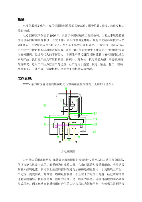
概述:电液伺服阀是电气-液压伺服控制系统的关键部件,用于位置、速度、加速度和力等的控制。
七O四研究所创建于1956年,隶属于中国船舶重工集团公司,主要从事舰船特辅机电设备的应用研究和设计开发工作,本所技术力量雄厚,拥有中高级科研技术人员500余人,专业技术人员300余人。
早在五十年代已开始研究、开发电气-液压产品。
七十年代开始研制和应用电液伺服阀,并在1981年研制诞生了我国第一台船用射流管电液伺服阀。
经过几代人的不懈努力,本所生产的CSDY型射流管电液伺服阀已成为系列产品。
我们的产品具有结构紧凑、体积小、寿命长、抗污染能力强、动态响应快、分辨率优,适用工作压力范围广等优点,已广泛用于航空、航海、冶金、化工、轻纺、塑料加工、石油冶炼、试验机械、电站设备和机器人等领域。
工作原理:CSDY系列射流管电液伺服阀是力反馈两级流量控制阀(见结构原理图),结构原理图力矩马达采用永磁结构,弹簧管支承着衔铁射流管组件,并使马达与液压部分隔离,所以力矩马达是干式的。
前置级为射流放大器,它由射流管与接受器组成。
当马达线圈输入控制电流,在衔铁上生成的控制磁通与永磁磁通相互作用,于是衔铁上产生一个力矩,促使衔铁、弹簧管、喷嘴组件偏转一个正比于力矩的小角度。
经过喷嘴的高速射流的偏转,使得接受器一腔压力升高,另一腔压力降低,连接这两腔的阀芯两端形成压差,阀芯运动直到反馈组件产生的力矩与马达力矩相平衡,使喷嘴又回到两接受器的中间位置为止。
这样阀芯的位移与控制电流的大小成正比,阀的输出流量就比例于控制电流了。
射流放大器因为没有像双喷嘴-挡板阀放大器的压力负反馈,所以流量和压力增益较高,因此该型阀分辨率极好,低压工作性能亦很好。
射流管电液伺服阀的特点:1、该阀的力矩马达采用整体焊接工艺,结构牢固,能在恶劣环境条件下正常工作。
2、独特的射流管放大器结构可以通过200μm的污染颗粒,而不发生故障。
3、单输入型的前置级如被堵时,伺服阀能自动复零,不会产生错误的“满舵”现象。
MOOG伺服阀D660 的中文样本
此目录中所述阀系列已顺利通过了欧洲电器标准要求的 EMC 测 试。请参阅电气控制部分的相关参考内容。
D661K、D662K、D663K 和 D664K 系列阀还适合在潜在爆炸性 环境、安全类型为 〃d〃(符合 DIN EN 50018 的 〃d〃 型防燃 外壳设备)等级 II 2G EEx d C-C2H2 T5、NEMKO 02ATEX272、 CE 0123 的设备中使用。重要事项:请注意安装尺寸和其它电气 连接方式有所变化。
04可选择的型故障保险如果bar必须用外控外排口可选择的外排口必须用四通阀需使用另一个t160lmin159gpm四通阀带对中弹簧需使用另一个t160lmin159gpm2x2通外接阀五通阀d660系列d661技术参数在先导级控制压力或系统工作压力为210bar3050psi油液粘度为32mm和油液温度为40参见推荐的控制连接方式的液压机能符号型号类型d661安装形式符合iso标准多一个iso440105阀的类型四通2x2通和五通第二级为标准滑阀先导阀伺服射流管servojet标准流量大流量先导级连接可选择内控式或外控式重量kglb5612356123额定流量bar75psi每一节流边lmingpm30807915921122113080791592112211工作压力先导阀
伺服射流管先导阀具有很高的无阻尼自然频率 (500 Hz),因此 这种阀的动态响应较高。
性能可靠 。 伺服射流管 ServoJet ® 先导阀能给出高效率的压
力(输入满标定信号时,可达 80% ∆p),对于长行程主阀芯 也可取得很可靠的位置精度。
也能获得较理想的控制力,使得即使有污染影响和液动力干扰
QN [l/min] = 阀的额定流量 ∆p [bar] ∆pN [bar]
- 1、下载文档前请自行甄别文档内容的完整性,平台不提供额外的编辑、内容补充、找答案等附加服务。
- 2、"仅部分预览"的文档,不可在线预览部分如存在完整性等问题,可反馈申请退款(可完整预览的文档不适用该条件!)。
- 3、如文档侵犯您的权益,请联系客服反馈,我们会尽快为您处理(人工客服工作时间:9:00-18:30)。
609伺服阀样本
(最新版)
目录
1.介绍 609 伺服阀
2.609 伺服阀的特点
3.609 伺服阀的应用领域
4.609 伺服阀的样本内容
正文
【一、介绍 609 伺服阀】
609 伺服阀是一种采用电子驱动方式的自动化控制元件,主要用于工业自动化控制系统中。
伺服阀通过对液压油的流量、压力和方向进行精确控制,实现对执行元件(如液压缸、马达等)的运动速度、位置和力的精确控制。
609 伺服阀具有高精度、高速度、高可靠性等特点,广泛应用于各种工业设备和生产线。
【二、609 伺服阀的特点】
1.高精度:609 伺服阀能够实现精确的流量、压力和方向控制,从而保证执行元件的运动速度、位置和力的精度。
2.高速度:609 伺服阀采用电子驱动方式,响应速度快,能够满足高速运动的要求。
3.高可靠性:609 伺服阀采用先进的设计理念和制造工艺,具有较高的故障排除能力和抗干扰能力,能够在恶劣的工作环境下稳定工作。
4.多功能:609 伺服阀具有多种控制模式,如速度控制、位置控制、力控制等,能够满足不同工况的需求。
5.易于维护:609 伺服阀结构简单,拆卸方便,便于维修和更换。
【三、609 伺服阀的应用领域】
609 伺服阀广泛应用于各种工业设备和生产线,如数控机床、机器人、自动化装配线、工程机械等。
在这些设备和生产线中,609 伺服阀能够实现对执行元件的精确控制,提高设备的运动精度、速度和效率,从而提高生产效率和产品质量。
【四、609 伺服阀的样本内容】
609 伺服阀的样本通常包括以下几个方面:
1.产品概述:介绍 609 伺服阀的基本概念、结构原理、主要性能参数等。
2.产品特点:详细介绍 609 伺服阀的高精度、高速度、高可靠性等特点。
3.应用领域:列举 609 伺服阀在各种工业设备和生产线中的应用实例。
4.安装与维护:介绍 609 伺服阀的安装方法、使用注意事项和维护保养方法。
5.规格与型号:列举 609 伺服阀的各个规格和型号,方便用户选择和购买。