全地形铰接式履带车辆转向与俯仰运动性能研究
履带拖拉机机械液压双功率流差速转向机构研究与设计

履带拖拉机机械液压双功率流差速转向机构研究与设计作者:莫毅松来源:《农业开发与装备》 2018年第5期摘要:通过对不同履带拖拉机机械液压双功率流差速转向系统的结构、速度特性、动力转向特性分析,提出新型机械液压双功率流差动转向系统结构-各档等半径转向机构,并以常州汉森机械有限公司生产的HM80履带拖拉机转向传动系方案为例,对它的传动设计原则和设计经验进行了总结,为履带式拖拉机的转向系统设计提供一种新的结构。
关键词:履带拖拉机;转向机构;等半径转向0 引言目前现有履带行走机构的转向机构大致分为三种结构。
1)机械式:如国产老款东方红履带拖拉机分离制动使两侧驱动轮获得不同的驱动扭矩达到转向的目的。
2)液力传动式:如履带式挖掘机、履带式装载机采用变量泵提供液压动力驱动履带,通过改变向两侧马达提供不同的流量,使两侧履带获得不同的速度实现方向上的偏转,达到转向的目的。
低速传动,传动效率低。
3)机械液压合流式:如新款洛阳东方红履带拖拉机、湖南农夫履带拖拉机、日本洋马拖拉机、以及国际上主流的新式坦克。
这种机构采用机械与液压双功率流差速转向技术。
这种技术来源于德国坦克的传动技术,1936年由欧洲一家公司研制成功SOMUA转向机,这项技术它在用不同的挡位工作时,会产生不同的转向效果。
每一个挡位都有一个规定转向半径,同时低挡实现的转向半径小,而高挡时实现的转向半径大,这与我们常规操作有些不同,即当方向盘偏转到一定的角度时转向半径是确定的。
图1 单功率流传动示意图图2 双功率流传动示意图1 新型机械液压双功率流差速转向机构研究内容对双功率流转向机构的理论及特性分析,导出特性关系式,分析行星排特性参数对传动性能的影响,为设计新型双功率流转向机构传动装置提供依据。
设计一种可以在不同的挡位工作时,会产生相同的转向效果-即转向半径仅与方向盘偏转角度有关,与其他结构参数无关的双合流转向机构,更适合一般的操作习惯。
2 结构分析这种方案中泵的传动在变速箱后(见图3),泵的排量随档位变化,设从变速箱输出端到泵的传动比为ibq基于以上的分析:图3 结构示意图图4 液压系统图速度特性:平均速度:v5L=2πrnf/(imibiz(1+k))+kEnf/(ibiqibq)(1+k)v5R=(2πrnf/ibimiz(1+k)-kEnf/(ibiqibq)(1+k)两条履带的平均速度V4PV5P=(vL+vR)/2=2πrnf/imibiz(1+k)左右履带差ΔV5ΔV5=v5L-vR=4πrnfEk/ibiqimibq(1+k)R5=B(vL+vR)/2(vL-vR)设R5为转弯半径R5=Biqibq/2kEiz动力从马达行星排传递路线没有变,因而动力特性如果忽略到马达的传递效率也一样,但比效率不能忽略,因为发动机经变速箱后转速降低了,特别是最低档在怠速工作时,传递到泵的转速非常低,会对泵的效率产生影响,这个方案需要对泵的最高转速和最低转速进行校对。
备受青睐的履带式全地形铰接装甲车
备受青睐的履带式全地形铰接装甲车目前,履带式全地形铰接装甲车得到了许多国家的青睐。
20世纪60~70年代期间,苏联和一些西方国家出现了第一批?M入连续生产阶段的铰接式运输车辆。
在此期间,瑞典赫格隆AB车辆公司曾经生产出了颇受人们欢迎的BV206型铰接式车辆,但这种车辆的载重能力仅为2吨。
芬兰也曾研制出了载重能力与BV206不相上下的类似车辆。
然而,苏联在同一时期研制推出的同类型车辆的载重能力最大的竟高达2吨!随后,苏联又陆续推出多种铰接式运输车辆,其中,载重能力在10~30吨之间的车辆比比皆是,给人们留下了深刻的印象。
苏联解体后,俄罗斯全面继承了这一发展优势,在拥有多年研究和试验经验的基础上,成功地研制推出了性能优良的“勇士”履带式全地形铰接运输车。
目前,俄罗斯防务产品出口有限公司正在向海外推销这种性能独特的车辆。
“勇士”的配置特征铰接式运输车辆实际上是用主动传动机构将两节车体连接成一辆车而成,具备较强的越野能力,可以顺利地穿越地形复杂的区域。
早在20世纪初,铰接式运输车辆就已经研制成功,但当时问世的铰接式运输车并没有得到有效的应用。
俄罗斯新研制的“勇士”全地形铰接式运输车是按照拖车的设计原理制造而成,两节车体之间利用铰链?M行连接。
前面的一节为驾驶室兼乘员舱,内装空调和通风换气系统等,除驾驶员外,还可以另外再搭载4~7名士兵,?M行物资运送时亦可以作为货物舱使用。
后面的一节既可以搭载士兵和装载货物,也可以作为一种武器平台,用来安装各种装备。
“勇士”的车体加装了一个由纵向、横向和斜向板条构成的箱形框架,这种刚性结构可以用来安装升降机、挖掘机、钻孔机和其它技术装备。
配置不同的装备后,可以将“勇士”铰接式运输车的载货平台改造成适于运送较长、较大或较重的装备。
“勇士”履带式全地形铰接运输车的最大特征是其地面和涉水通过性能非常卓越,此外,其牵引能力也相当强,且载货空间大,行程长。
值得一提的是“勇士”的涉水行?M能力,在水中,它借助于履带划水推?M车辆前行,水中推?M 速度可以达到4~5千米/小时,可以在无准备的情况下出水登岸。
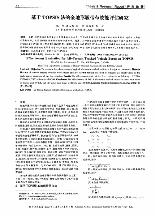
基于TOPSIS法的全地形履带车效能评估研究
p r r n ep rmee fte f ev hce.1 tl e e e t e e sod ro h v e ilsi sfl w n : B ef ma c aa tro h v e ils  ̄mlsTh f ci n s re fte f ev hce s a ol ig o i l v i o VSI O: B 0 S> J 1 V2 6 Y8 3> B o c > B 0 . 伪尬 1 rn o V2 6 C 0 啪 . T e e e t e e so Y8 3 al tranta k d vh cei etrta h s h f ci n s J 1 l eri rc e e il sb t h nto e f v f — e
术 参数 指 标 ,运 用 T P I O SS法进 行 效 能评 估 并 排 序 。结 果 :五 种 典 型 全 地 形 履 带 车 辆 的 效 能 水 平 排 序 为 B S 0型: V 1
B 26 V 0 S型 >J 8 3型 >野 马 型 >B 2 6型 。 结论 : Y1 V0 目前 国 内 的 J 8 3型 “ 地 虎 ” Y1 全 全地 形履 带车 的 效 能 水 平 较 B SO V I
f rnoadB 2 6 b ti r h hs f S 0a dB 2 6 . ie eMe i up n un l 1 ,3 o Boc n V 0 , u tl os t ntoeo V 1 n V 0 S[hn s dc l q ime t o ra,0 2 3 lw e a B c aE J 2
型和 B 26 V 0 S型 全 地 形 履 带 车还 有 一 定 的 差 距 , 已超 过 “ 马 ” 和 B 2 6型 全 地 形履 带 车 , 但 野 型 V0 具有 较 好 的 效 能 水平
履带车辆硬地面转向阻力矩算法的研究
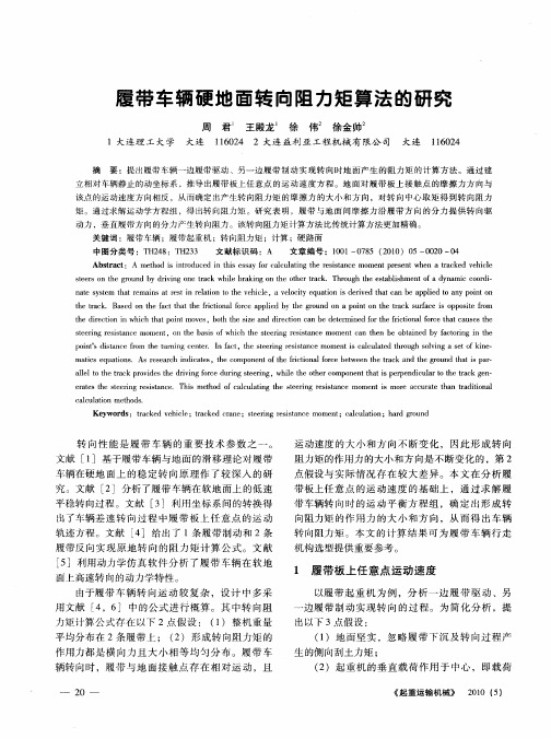
立相对车辆静止的动坐标 系,推导 出履带板上任意点 的运 动速度方 程。地 面对履 带板上接触 点的摩擦 力方 向与 该点的运动速度 方向相反 ,从而确定出产生转向阻力矩 的摩擦 力 的大小和方 向 ,对转向 中心 取矩得 到转向阻力
矩 。通 过求 解 运 动 学 方 程 组 ,得 出 转 向 阻 力矩 。研 究 表 明 ,履 带 与 地 面 问 摩 擦 力 沿 履 带 方 向 的 分 力 提 供 转 向驱
p i t itn e fo te t r i g c ne . I a t h te ig r ssa em o nti ac lt d t o g o vn e fk n — o n’ dsa c r m h u n n e tr nf c ,te se rn e itnc me sc lu ae hr u h s l ig a s to i rs ac n iae ,t ec mp n n f h it n l o c e w e h r c n e go n a a — t q ai s e o e e r h id c ts h o o e t e f ci a re b t e n t e t k a d t r u d t ti p r ot r o f a h h s l e o t c rvd ste d i n c u i te i g h l t t e o o e t h ti p r e dc l r ot e t k g n allt eta k p o i e h r i gf re d r g se rn ,w i eoh rc mp n n a e p n iu a h r c e — h r v o n eh t s t a ca e h te i g r s tn e h s meh d o ac l t g t e s e n e itn e mo n s mo e a c r t h n t dt n l rt st e se rn e i a c .T i s t o fc lu ai h t r g r ss c me t i n ei a r c u a e t a r i o a a i
铰接式自卸车优先转向系统方法研究

2023.02 建设机械技术与管理371 研究背景铰接式自卸车是一种可适应恶劣路况的非公路工程车辆。
通过铰接体连接前、后车架,并利用车架两侧的转向油缸控制车头转动,实现车辆转向。
铰接式自卸车越野能力强、通过性好,在热带地区的矿山开采、水利水电工程等空间受限及泥泞湿滑的场所得到广泛应用。
2 厂家方案2.1 沃尔沃铰接式自卸车优先转向系统沃尔沃是铰卡的发明者,在1966年第1台铰卡下线,到1980年铰卡下线突破10000台,并在当年对外宣布铰卡市场占有率超过50%。
之后,沃尔沃铰卡产品不断改进升级,产品型谱不断完善,在2016年推出了50周年纪念款A60H ,载重可达55吨。
铰接式自卸车优先转向系统方法研究Research on the Method of Priority Steering Systerm for Articulated Dump Truck高新功 姚锡江 路亚文(徐州徐工矿业机械有限公司,江苏 徐州 221000)摘要:优先转向系统的合理设计直接影响着铰接式自卸车的安全,并且能明显减小系统的功率损耗。
本文通过对沃尔沃、卡特彼勒铰接式自卸车优先转向系统方案进行研究,详细分析各种不同方案的要求、原理和特点。
关键词:铰接式自卸车;优先转向;液压系统中图分类号:TD57 文献标识码: A图1 铰接式自卸车运输作业为保证铰接式自卸车的安全可靠性,市场上的车辆均配置了优先转向系统。
优先转向系统是指车辆在正常行驶中,液压泵提供的油液需要优先供给转向系统(制动系统一般是独立供油)。
满足了系统的转向需求,车辆才能够按照既定路线行驶。
因此,优先向转向回路提供足够的压力和流量才能保证转向系统可靠。
目前,沃尔沃、卡特彼勒、贝尔铰接式自卸车厂商均根据自身整车系统的特点,配备了优先转向系统。
这些优先转向系统各具特色,有着完全不同的实现方法,成为其他铰卡厂家学习和借鉴的模板。
1.液压油箱2.液压泵3.转向阀4.方向盘5.过载阀组6.转向油缸图2 沃尔沃 A45G 优先转向原理图现以沃尔沃铰卡的热销车型A45G 的优先转向系统来进行分析研究,方案的本质是切断去往举升系统的油液,优先保证转向。
一种电动履带耕整机的研制及试验

一种电动履带耕整机的研制及试验周春健,俞志轩,唐宁静,李一昕(上海市农业机械研究所,上海市 201106)摘要:针对目前设施内耕整作业环节人工劳动强度大,传统内燃机动力污染大,能源利用率低等问题,研制出一种电动履带耕整机。
阐述了整机的结构与工作原理,对关键部件的参数进行了设计,开发了一套具有2种作业模式的控制系统,实现对电动履带耕整机无人驾驶作业和无线遥控作业。
通过田间试验对电动履带耕整机的作业性能进行测试,试验结果表明在耕整机前进速度1 m/s,旋耕电机最大消耗功率11.8 kW,旋耕深度均值15.4 cm,稳定性系数93.5%。
试验结果表明,各项指标满足设计要求,该研究可为设施内耕整作业提供参考。
关键词:电动耕整机;研制;试验0 引言耕整作业是农业生产中重要的环节。
目前的耕整作业主要以有人驾驶的耕整机作业为主,作业时驾驶人员需集中精力控制机具作业方向及时调整作业路径,作业环境较恶劣,劳动强度较大。
同时采用内燃机动力的耕整机在设施内作业时排放污染物较多,容易造成环境污染,影响驾驶人员健康及农产品质量。
国内高校对于电动旋耕机的研究以理论为主,田硕对新型整体式电动旋耕机结构设计及轻量化进行了研 究[1];柴媛欣对电动微耕机动力系统的匹配进行了研 究[2];李亮等设计了一种新型环保电动微型旋耕机[3]。
目前,以电动微耕机为代表的新能源机具在农业机械领域得到持续关注与研究,本文根据设施内旋耕作业需求,设计一种电动履带耕整机以减少劳动作业强度,减少碳排放,提高设施内耕整作业质量,对于早日实现碳中和目标具有积极意义。
1 整机结构与工作原理1.1 整机结构电动履带耕整机如图1所示,主要有罩壳、履带底盘、控制箱、动力电池、电动液压推杆、旋耕部件组成。
控制箱安装于履带底盘的前端,动力电池安装于履带底盘的中间位置,旋耕部件通过三点悬挂与履带底盘相连接,旋耕部件的升降通过电动液压推杆完成。
a耕整机主视图b 耕整机主视图1.罩壳2.履带底盘3.旋耕部件4.控制箱5.动力电池6.电动液压推杆图1 电动履带耕整机结构简图1.2 工作原理电动履带耕整机由电池提供底盘行走以及旋耕动力,通过远程计算机下达作业指令使耕整机自动寻找工作点位按照预先规划好的轨迹进行耕整作业或者采用手机遥控的方式控制耕整机进行自动耕整作业。
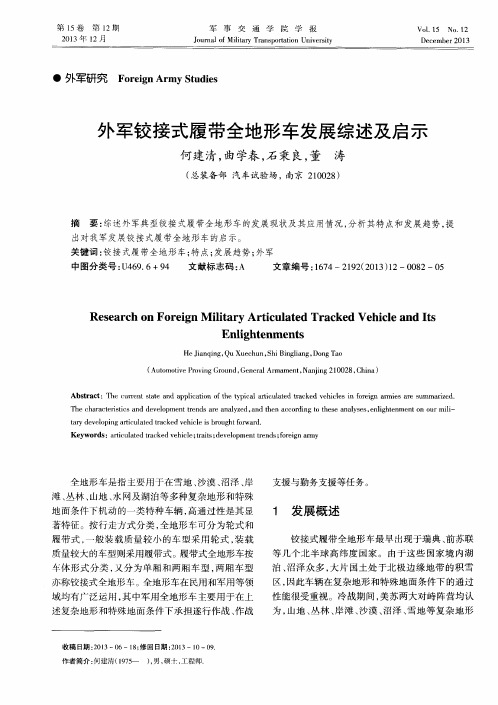
外军铰接式履带全地形车发展综述及启示
8 3
和 特殊 地 面都 将 会成 为 未来 的陆 战场 , 但 在 这些 复 杂地域 , 一般 的轮 式 、 履 带式 车辆 通 过 性 能 下 降严 重, 部 队 机动 能力 和后 勤保 障 能力 无 法 满 足作 战要 求 。为解 决部 队实 际需 要 , 借 助科 技进 步 , 瑞典 、 原 苏联 、 芬兰 、 美 国、 加 拿 大等 国家竞 相 开 展 了铰 接式 履 带全 地形 车 的研制 工作 。这个 时期 所发 展 的车 型 主要用 于寒 冷积 雪 地 区进 行人 员 输送 和 物 资运 输 , 故 又称 为 雪地 车 。 冷 战结 束后 , 特别 是进 入 2 l 世纪 , 战争 样 式 发 生 了重 大 改 变 , 全 面 大 战 的可 能 性 降 低 , 而 围绕 热 点地 区 的 冲 突却 不 断 增 加 , 具有非线式 、 非 对 称 性
全 地形 车是 指 主要 用 于在 雪地 、 沙漠 、 沼泽 、 岸
支援 与勤务 支援等 任务 。
滩、 丛林 、 山地 、 水 网及 湖泊 等 多种 复杂 地 形 和特殊 地 面条 件 下机 动 的一类 特种 车 辆 , 高通 过性 是 其显
著特征 。按 行 走方 式 分类 , 全 地形 车 可分 为轮 式 和 履带式 , 一 般 装 载 质量 较 小 的 车 型 采用 轮 式 , 装 载 质 量较 大 的车型则 采用履 带式 。履带式 全地形 车按
De c军研究
F o r e i g n A r my S t u d i e s
外军铰接式履 带全地形车发展综述及启 示
何建 清, 曲学春 , 石秉 良, 董 涛
( 总装备 部 汽车试验 场 ,南京 2 1 0 0 2 8 )
改装的“骏马”--英国“疣猪”全地形车
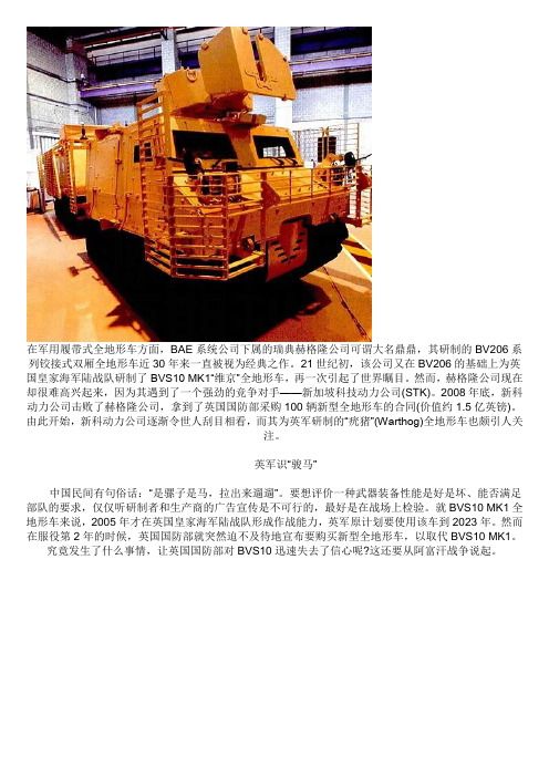
在军用履带式全地形车方面,BAE系统公司下属的瑞典赫格隆公司可谓大名鼎鼎,其研制的BV206系列铰接式双厢全地形车近30年来一直被视为经典之作。
21世纪初,该公司又在BV206的基础上为英国皇家海军陆战队研制了BVS10 MK1“维京”全地形车,再一次引起了世界瞩目。
然而,赫格隆公司现在却很难高兴起来,因为其遇到了一个强劲的竞争对手——新加坡科技动力公司(STK)。
2008年底,新科动力公司击败了赫格隆公司,拿到了英国国防部采购100辆新型全地形车的合同(价值约1.5亿英镑)。
由此开始,新科动力公司逐渐令世人刮目相看,而其为英军研制的“疣猪”(Warthog)全地形车也颇引人关注。
英军识“骏马”中国民间有句俗话:“是骡子是马,拉出来遛遛”。
要想评价一种武器装备性能是好是坏、能否满足部队的要求,仅仅听研制者和生产商的广告宣传是不可行的,最好是在战场上检验。
就BVS10 MK1全地形车来说,2005年才在英国皇家海军陆战队形成作战能力,英军原计划要使用该车到2023年。
然而在服役第2年的时候,英国国防部就突然迫不及待地宣布要购买新型全地形车,以取代BVS10 MK1。
究竟发生了什么事情,让英国国防部对BVS10迅速失去了信心呢?这还要从阿富汗战争说起。
BVS10 MK1“维京”全地形车英国在追随美国出兵阿富汗之后就陷入了泥潭。
面对塔利班武装布设的路边炸弹、飘忽不定而又无处不在的袭扰,驻阿英军的装备暴露出了许多缺陷,最突出的是防护力不足,导致大量英军官兵伤亡。
尽管BVS10 MK1全地形车是新型车辆,在装甲防护能力上给予了较高重视,但由于研制时阿富汗战争还没有开打,所以其装甲防护能力与此前的装甲强化型BV206S相比并无本质性提高,仅能防御轻武器的射击和距离较远的榴弹破片。
而当BVS10 MK1研制成功、开始装备英军时,阿富汗战争已经打了4年,塔利班对路边炸弹的运用已经日臻纯熟,以BVS10 MK1当时所具有的装甲很难对抗。
履带结构设计与参数对车辆性能影响

履带结构设计与参数对车辆性能的影响摘要:根据履带车辆动力学, 分析了履带车辆的接地长宽比, 即履带接地长度与履带中心距的比值对行驶性能的影响。
分析表明,接地面积一定时,长而窄履带比短而宽的履带行驶阻力要小;当履带接地面积相同时,长而窄履带比短而宽的履带有更大的切向牵引力;长宽比设计得太大会增加转向难度, 但是太小会影响行驶稳定性, 设计结果应满足原地中心转向的要求, 同时保证有合理的临界再生转分析结果为整车结构参数设计提供了理论依据。
关键词:履带车辆; 行驶性能; 参数设计中图分类号: u491.2+55 文献标识码: a 文章编号:crawler structure design also parameters on the vehicle performance impactabstract: according to analysis of caterpillar vehicle dynamics, the caterpillar vehicles grounding aspect ratio, namely the crawler grounding length l and crawler center distance of driving the ratio of b properties. analysis shows that certain grounding area, long and narrow than shorter and wider track the crawler driving resistance to small; when the crawler diam-eter grounding area, long and narrow than shorter and wider track the crawler have greater tangential traction; the aspect ratio design too congress too difficult, but increased to affect the driving stability, the designresult should satisfy the requirements of in-situ center steering, while guaranteeing that have reasonable critical regeneration turn analysis results of vehicle structure provides theoretical basis for designing parameters. keywords: caterpillar vehicles; driving performance; parameter design1. 对车辆外部滚动阻力的影响履带接地长度l和履带中心距b是履带车辆非常重要的两个整车结构参数, 对履带车辆的行驶性能尤其是转向性能有很大关系 , 合理地设计履带车辆的接地长宽比对实现整车良好的行驶性能具有重要意义。
车辆工程专业毕业论文外文翻译---履带车辆转向机构的研究现状及发展趋势
The Track Vehicle Changes Direction Research Present Condition and DevelopmentTrends of The Organization1 change direction the research present condition of the organizationDifferent classification in basis method, the track vehicle changes direction organization can according to vehicle is in change direction process the power flows of deliver the way is divided into the single power flows to change direction the organization to flow to change direction the organization with a power, and also can according to in change direction process two the sport of side trackses have no the contact but is divided into the independent type change direction the organization with bad soon the type changes direction the organization.1.1 single powers establish a certain changing direction the organization after flowing change direction the single power in organization flow to change direction the general structure in organization method is at became soon the organization, is the most simple method to constitute track vehicle change direction to spread to move.The single power flows to change direction the organization to change direction the organization most in brief, among them most in common usely change direction the clutch, single bad soon the machine, double is bad soon the machine, planet changes direction organization etc..Change direction the clutch[1,2] is all a friction that several types rub the clutch, depending the friction surface to deliver to turn the , being the separation some on changing direction the clutch laterally, can reduce or cut off that side drive a round delivers of turn the make vehicle changed direction.Change direction the size of the radius from drive a decrease for spreads to turn the measures namely the degree that clutch separate decides.Change direction the clutch is simple because of the construction, manufacturing convenience, got the extensive application on the small scaled track in inside in earlier period type tractor, bulldozer.But because its manipulatethe sex bad, produce the efficiency low, can consume bigger, enlarge continuously along with the track vehicle power, change direction the application of the clutch will suffer certainly of restrict.SingleBad soon the machine changes direction the organization[2,3] can make vehicle several why the speed of the center position still keeps in change direction process the original driving the car straightly is soon, being a When the complete system in side move, change direction the radius over small, but another side track speed over high, change direction the Cape speed over big, for this reason a power for needing changing direction power very bigly, would outrunning generally launching machine restrict, if the pilot keep on changing direction, have a little bit the immodesty and then will make launch the machine fire, as a result can depend to slip to whet, using than the greater half path changes direction, or pole is not fair and softly break to change direction continuously with the lesser half path.Therefore this kind of is single bad soon the machine change direction the organization to no longer adopt almost now.The speed that a speed for differing soon machine changing direction organization[3,4] can making track vehicle at changing direction slowly soon side track lowering is equal to the fast side track the increment, the for this reason vehicle changes direction of average speed and straightly the speed that drive same alike.But because a variety for badly soon machine can't completely system moving first side track, vehicle can't originally changing direction, and changing direction radius scope has no usage to change direction the clutch big, changing direction the going smoothly worse.While changing direction, the fast side track accelerates, therefore launching the affixture of the machine carry the ratio adoption change direction the clutch big.The double is bad soon the machine be constituted by wheel gear of change direction the organization, with change direction the clutch compare the spare parts number little, bear to whet the sex good, the life span is longer.The planet changes direction the organization[4,5] moves with the system from a planet a department the machine constitutes.The operation planet the system on the organization moves the machine can change two sides drives the round drives the dint size make vehicle changeddirection.It is that type of to change direction the organization opposite in change direction the clutch change direction the organization can deliver the bigger changing direction the dint , can realize an athletic and fixed stalk wheel gear organization fall through of two free a planet for of flat-out decomposition with synthesizing, planet organization a three dollar as have the bad relating to soon; change direction the organization to much order to deliver the motive, and the internal path in organization faces the dint mutually equilibrium.But is complicated because of its construction, only industry in big power tractor, bulldozer and other heavy type vehicle last application.Single weakness that power change direction is obvious, vehicle only contain several fix of change direction the radius, press to rule not of change direction When the radius change direction, want to is slipped by friction a piece to whet to realize, and is hard to get the stability change direction the radius accurately; the next in order in change direction process rub a dollar piece of violent slip to whet to will bring to have fever with wear away, make spread to move the efficiency lower, especially in the big power change direction work appearance next, would exsit the bigger power lose, with the result that often need to be declined to change direction soon; moreover, the violent friction also make easy damage in organization, cause the work dependable bad, the life span lower.1.2 pairs of powerses flow to change direction the organization after launching machine, will launch the machine power be divided in to become soon with change direction two roads be juxtaposed to deliver, ising a double of powers to flow to change direction the organization.A power flows to change direction the organization will used for keeping the pushes forward of become soon the organization is different from result in leftly, the right side track speed differs of change direction the organization to be juxtaposed in spread move department, change direction the organization when the vehicle keeps the did not result in twoth the speed of side trackses are bad, while changing direction, became to flow each file of offering soon to drive the speed straightly with change direction the organization results in of two the speed of side trackses differ to remit to flow, realizing the vehicle change direction.(1)the machine type a power flow to change direction the organization to flow the foundation top that change direction the organization to appear at the earliest stage in the single power of was a machine to kept the with changed direction two powers flowed all from machinery to realized type a power to flowed to change direction the organization[3].It is this kind to change direction the organization main from two become soon box( a lord become soon the box, a cent moves a box of), the planet wheel gear organization, clutch moves with the planet organization system the machine constitutes, the single power flows to change direction in changing direction function the organization has the very big increasing, but it still change direction the radius is to have the class.The file is more low, getting of change direction the radius more small; the file is more high, getting of change direction the radius more big.Can't still adapt to the vehicle road in all different curvatures on the tactful track that change direction to drive with the demand, also can't expel parts of coalescences rub a piece proceeds to slip to whet to change direction and from slip to whet an a series of problem for bringing.(2)the machine liquid press type a power flows to change direction the organization machineThe type of changes direction the organization changes direction the function easily under the influence of the pilot's driver's technique, physical strength term moving the machine to wear away with the clutch, system, and bring the pilot the fatigue easily.Give or get an electric shock along with the machine the liquid press and technical development in engineering in machine in person, the machine type change direction the organization to will be eliminated on the big power tractor, bulldozer...etc. engineering vehicle necessarily.Press in the l ast additional liquid in system in machine the liquid of —that pump the motor presses the machine — liquid drives to press to change direction the system will get the application gradually.The machine liquid press type a power flows to change direction the organization[5,6] from launch the machine and change the deal pump, control valve, fixed amount motor, many files become soon box and empress bridges change direction to differ to move the organization constitutes.Itwill spread to flow from the machine that launch the machine power in many files became soon the importation stalk of the box last cent flow, all the way flow through was pressed by liquid pump- liquid press motor constitute of change direction adjust soon system; another all the way flow through many files became soon box, finally experienced star row top confluence, then was lined up by planet of some a the parts( such as planet) spread to the vehicle to spread to move the stalk top eventually.Because the liquid presses to pump to press with the liquid the motor can have no the class controls, therefore using the this type of changing direction the organization since can acquire the carAn a lot of weakness for twoth lateral speeds differing realizing having no class controling, again overcoming machine type changing direction organization.If the liquid presses the motor do not work, only coming from central spread the dynamic power flow, the vehicle makes the straight line drives; if only have the liquid that come from the power press the motor flows, the vehicle can realize to change direction radius as the zero changing direction originally; if input at the same time two road powers flow, because the liquid presses the motor can realize to have no the class controls, for this reason vehicle two side tracks drive the rotation to have soon and will barely do much more endless, can get the much more endless changes direction the radius, can immediately realize to have no the class changes direction, pilot as long as manipulate to change direction the dish turns to move the liquid presses the device, can make vehicle driven along the certain arc stablely.This kind of changes direction the organization not only have the construction good, have no the friction a piece, life span is long, the efficiency is high and work dependable, arrange simple, maintain the adjustment little and lower to can consume to wait the characteristics the outside, but also it is not a motive to pass the part or cut off all a side track in working function to the system move a the side drives a the round realizes to change direction of, but two side tracks deliver the motive always, can realizes nicely like this the motive change direction, basic ascend a safety for slippery phenomenon, being applicable to proceeding being partial to carrying pushing soil with cutting off root homework; at sloping fields changing direction can't appearing" conversingdirection" phenomenon, increases vehicle that dissolves the track; because of changing direction do not cut off the motive, the average car of the for this reason vehicle does not lower soon; the track do not stop driving, breaking to the soil little, in loosenning soft soil of pass the sex good; change direction the size of the radius can control arbitrarily, increasing the flexibility of the track vehicle, change direction steady; change direction vehicle can develop with drive the high work in same function straightly; realizes easily a the root manipulates the pole to control in to back with change direction.2 change direction the pure liquid in trend(1)in development in organization press to have no the class changes direction the organization wants to realize the track vehicle changes direction the radius can control and continue to have no the class changes of change direction the function, the adoption capacity type liquid presses to pump to press with the liquid motor etc. has no the class become soon a piece is a more realistic viable method.The pure liquid presses to change direction the organization[7 9] of ~ss pass to pump of positive and negative two directions have no the class changes the deal regulates, realizing to launch the mobile dint was spread by double to move to change direction the road arrives to remit the popular star row has no the class changes of spreading and moving ratio, end realize the vehicle face or so two change direction laterally radius can continue to have no the class the variety keeps the , pass the liquid press to pump with the liquid press the motor shuts the lock( change the row that deal pump measureses for zero) to realize to change direction the zero to shut the lock axially, from but keeps to keep the stablely.Under the situation of becoming soon the organization hangs the blank on schedule to change direction, launch machine a power for sending out all to press from the liquid that change direction the road a piece deliver, can realize the vehicle change direction originally.The current liquid presses the industry level returns the hard getting the power enough and big and the good liquid in function presses a dollar an efficiency for, and the liquid presses the system low, this is the biggest obstacle that pure liquid press to have no the class change direction the technique develops.(2)the compound changes direction organization as to overcome the pure liquid presses the above blemish that change direction the organization, appearing now the small liquid in power in various adoptions press the liquid of a dollar piece presses the compound changes direction the project[7].A pump a motor project: this project is to solves the liquid press the direct and the most simple project in shortage in a power in a dollar, its function press with pure liquid to change direction same, but two sets of liquids press a piece merge to make the organization's physical volume weight bigger, the efficiency is still lower.The machine liquid presses to reunite the project: that project is adopting a double of flowing the liquid press to change direction of at the same time, reserve a set of machines change direction the organization.Make use of the power not very of the liquid presses a dollar the piece realizes the greater half path changes direction of have no the class variety continuously; make use of the organization that machine change direction lesser half path realizes the class changes direction.This kind of change direction the organization falls through whole radius scope has no the class variety.A radius liquid presses to change direction the project: that project adoption contain two kinds of exportations soon the liquid that compare presses the motor, when the good road ascends to change direction adoption the higher exportation turns soon, native out of fix the hour then change to output with the low speed to overcome bigger changing direction the resistance.The liquid presses the liquid dint compound changes direction the project: that project presses with the liquid of the limited power a piece proceeds to have no the class changes direction, the help matches the machine accidentally at change direction the liquid press the motor dint not enough hour on time provide the help .That project although reduce the liquid press a piece efficiencies would be much lower.In fine, adopt the liquid press a dollar a point for having no class becoming soon characteristic to realizing track vehicle having no class changing direction is good choice, solving liquid pressing a dollar a power shortage then is low with the efficiency that direction is investigative.(3)the machine liquid presses the consecution has no the class changesdirection the organization machine liquid presses the consecution has no the class changes direction the organization[10 21] of ~ss are in simple liquid pressing cent in machine spreading the foundation that move the principle, adopting the different machine organization parameter combine, and press with liquid a dollar the piece matches with of a kind of latest model changes direction the organization.It can guarantee at continue to have no the class output the next applied small liquid in premise that turn to press the total power in an exportation for significantly increasing vehicle in a dollar soon, and its spread to move the efficiency far far ahead pure the liquid presses to change direction the organization spreads to move the efficiency.It represents the development direction that track vehicle change direction organization.The research develops the good machine in function liquid presses the consecution has no the class changes direction the organization, excellent turn to match the that type of turning. Construction parameter that face organization is the point lesson of the current vehicle engineering realm.履带车辆转向机构的研究现状及发展趋势1、转向机构的研究现状依据不同的分类方法,履带车辆转向机构可根据车辆在转向过程中功率流的传递方式分为单功率流转向机构和双功率流转向机构,也可根据在转向过程中两侧履带的运动有无联系而分为独立式转向机构和差速式转向机构。
全地形车传动型式探讨
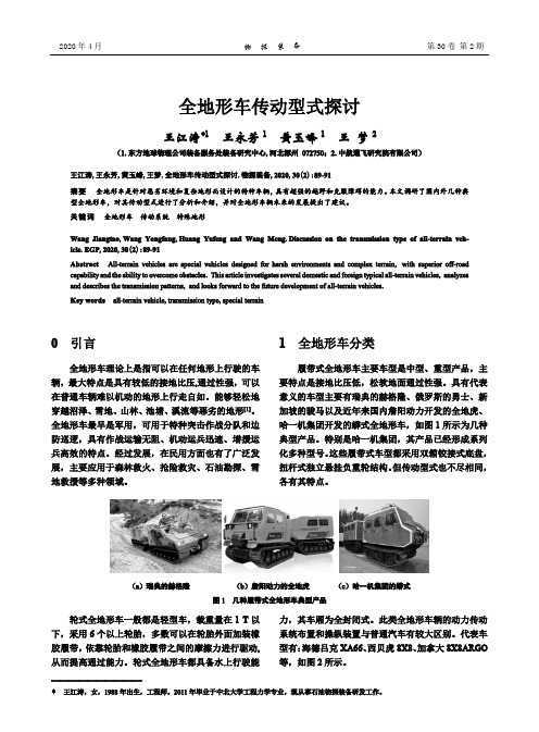
2020年4月 物 探 装 备 第30卷 第2期全地形车传动型式探讨王江涛*1 王永芳1 黄玉峰1 王 梦2(1.东方地球物理公司装备服务处装备研究中心,河北涿州 072750;2.中航通飞研究院有限公司)王江涛,王永芳,黄玉峰,王梦.全地形车传动型式探讨.物探装备,2020,30(2):89-91摘要 全地形车是针对恶劣环境和复杂地形而设计的特种车辆,具有超强的越野和克服障碍的能力。
本文调研了国内外几种典型全地形车,对其传动型式进行了分析和介绍,并对全地形车辆未来的发展提出了建议。
关键词 全地形车 传动系统 特殊地形Wang Jiangtao ,Wang Yongfang ,Huang Yufeng and Wang Meng .Discussion on the transmission type of all-terrain veh-icle .EGP ,2020,30(2):89-91Abstract All-terrain vehicles are special vehicles designed for harsh environments and complex terrain , with superior off-road capability and the ability to overcome obstacles . This article investigates several domestic and foreign typical all-terrain vehicles , analyzes and describes the transmission patterns , and looks forward to the future development of all-terrain vehicles . Key words all-terrain vehicle ,transmission type ,special terrain0 引言全地形车理论上是指可以在任何地形上行驶的车辆,最大特点是具有较低的接地比压,通过性强,可以在普通车辆难以机动的地形上行走自如。
履带行走机构的运动学和动力学

履带行走机构的运动学和动力学一、履带行走机构的运动学履带行走机构在水平地面的直线运动,可以看成是台车架相对于接地链轨的相对运动和接地履带对地面的滑转运动(牵连运动)合成的结果。
当履带相对地面没有滑转运动时,根据相对运动的原理,台车架相对接地链轨的运动速度与链轨相对于台车架的运动速度数值相等,方向相反。
因此,可以通过考察链轨对静止的台车架的运动来求取两者之间的相对运动速度。
此时履带在驱动轮的带动下以一定的速度围绕着这些轮子作“卷绕”运动(图1-2)。
由于履带链轨是由一定长度的链轨节所组成的,如通常的链传动一样,履带的卷绕运动速度即使在驱动轮等速旋转下,亦不是一常数。
从图1-2中可以看到,当履带处于图中1所示的位置时,履带速度达最大值,并等于:式中:—驱动链轮的节圆半径;当履带处于图中2所示的位置时,履带速度最低,等于:式中:—驱动链轮的分度角,; —驱动链轮的有效啮合齿数。
由此可见,即使驱动轮作等角速旋转(为常数),台车架的相对运动也将呈现周期性的变化,从而使车辆的行驶速度也带有周期变化的性质。
履带卷绕运动的平均速度可通过驱动轮每转一圈所卷绕(转过)的链轨节的总长来计算。
0r βK Z 360=βK Z K ω设:—链轨节矩,m ;—驱动轮转速,r/min 。
则履带卷绕运动的平均速度可由下式计算:当履带在地面上作无滑动行驶时,车辆的行驶速度显然就等于台车架相对于接地链轨的运动速度,后者在数值上等于履带卷绕运动的速度。
通常,将车辆履带在地面上没有任何滑移时,车辆的平均行驶速度称为理论行驶速度,它在数值上应等于履带卷绕运动的平均速度,亦即:由(1-4)可增加时,则履带卷绕运动速度的波动就减小。
为了简化履带行走机构运动学的分析,通常将这种极限状态作为计算车辆行驶速度的依据。
此时,假设履带节为无限小,且相对于驱动轮无任何滑动。
根据上述假设,履带就具有图1-4所示的形状。
当驱动轮齿数相当多时,此种假设是可以容许的。
铰接式客车转向动力学仿真及其稳定性控制策略

摘要铰接式客车作为BRT快速公交系统的重要车型,具有载客量大、运营成本低的优点,近年来成为了研究热点。
铰接式客车由主车、副车及铰接装置组成。
由于结构复杂,铰接式客车的速度得到了很大限制。
为了解决铰接式客车在高速行驶时的稳定性问题,本文利用直接横摆力矩控制方法对铰接式客车进行了稳定性控制策略的研究。
本文首先分析了铰接式客车在稳态转弯时,可能发生的动力锁死问题,并基于此设计了以最优主副车夹角为目标函数的优化模型,优化模型的约束方程包括主、副车车身的几何参数限制以及国家标准对铰接式客车转弯通道宽度的限制标准。
优化后,主副车夹角显著降低,提高了铰接式客车稳态转弯能力。
针对铰接式客车高速转弯时的瞬态响应特性,本文建立了铰接式客车包含主车模型、副车模型、饺接装置模型在内的十五自由度整车模型,并仿真分析了铰接式客车在三种方向盘转角输入时,不同车速下,主、副车的运动响应。
仿真结果表明,方向盘转角较小时,铰接式客车在不同车速下都有良好的转向性能,而当方向盘转角较大且车速较高时,铰接式客车出现转向失稳的危险工况。
为了提高铰接式客车高速工况下的转向能力,对其施加直接横摆力偶矩控制,直接横摆力偶矩通过主、副车制动器差动制动产生。
通过理论分析,确定了直接横摆力偶矩的控制目标为主车横摆角速度、质心侧偏角和副车质心侧偏角,并推导了其理想模型。
同时设计了以副车质心侧偏角归零为控制目标的PID控制器和主车质心侧偏角及横摆角速度跟随其理想模型的PID控制器和模糊控制器。
控制结果表明,当副车控制方式为PID控制且主车控制方式为PID模糊联合控制时,铰接式客车的运动响应品质最优。
关键词:汽车工程;铰接式客车;直接横摆力矩;稳定性;车辆动力学AbstractAs an important bus model of BRT system, articulated bus has attracted a mass of attention for its advantages such as large capacity and low operating costs. The articulated bus consists of main bus, sub-bus and articulated devices. Due to the complex structure, the speed of articulated bus has been very limited. In order to solve the problem of stability of articulated bus when driving at high speed, the stability control strategy of the articulated bus has been studyed with the direct yaw moment control method being used in this paper.In this paper, the potential lock-up problem of articulated bus when turning in steady-state was analyzed initially. Optimization model was designed based on this, with the angle between main bus and sub-bus as the objective function. The constraint equations of the optimization model included the geometric parameters of the main and auxiliary vehicle body and based on national standard of the limits of the width of the articulated bus turning channel. After optimization, the angle between main bus and vice bus was significantly reduced,and the turning ability of articulated bus had been improved.To obtain the transient response characteristics of articulated bus during high-speed turning, a 15-DOF vehicle model of articulated bus including the main vehicle model, deputy vehicle model and dumpling device model was established in this paper, and then simulated the motion response of the main and sub vehicles under the different speed of the articulated bus when the three steering wheel angles are input.Simulation results show that when the steering wheel angle is small, articulated bus has good steering performance at different speeds, while the steering wheel angle is large and the speed is high, articulated bus has potential of instability.In order to improve the steering capacity of articulated passenger bus when driving at high speed, the direct yaw moment control was applied, and the direct yaw moment is generated by the brake differential of the main and sub bus. Through theoretical analysis, the control target of the direct yaw moment is determined as the yaw velocity of main bus, side slip angle of main bus and sub-bus, and the ideal model was deduced based on it. Meanwhile, the PID controller was designed, which targets the side slip angle of the sub vehicle was zero ,and PID controller and fuzzy controller are designed to make the yaw angular velocity and side slip angle of the main bus follow the ideal model .The control results show that when the sub-bus was controlled by PID control and the main bus was controlled by PID fuzzy joint control, the motion response quality of the articulated bus is the best.Keywords: Automotive Engineering; Articulated bus; Direct yaw moment; Stability; Vehicle dynamics目录摘要 (I)Abstract (II)第一章绪论 (1)1.1 课题背景及意义 (1)1.2 国内外研究现状 (2)1.2.1 铰接式客车的发展现状 (2)1.2.2 国内外关于汽车操纵稳定性相关研究历史及现状 (3)1.2.3 车辆操纵稳定性控制方法 (6)1.3 主要研究目的 (10)1.4 主要研究内容 (10)第二章铰接式客车车身参数的优化设计 (12)2.1 铰接式客车转弯特性分析 (12)2.2 优化设计及分析 (14)2.2.1 设计变量及优化设计目标函数的确定 (14)2.2.2 约束条件的确定 (16)2.3 优化设计程序实现 (18)2.3.1 优化设计结果 (18)2.3.2 讨论和分析 (20)2.4 本章小结 (21)第三章铰接式BRT客车动力学模型及仿真分析 (22)3.1 引言 (22)3.2 轮胎运动坐标系 (22)3.3 轮胎模型 (23)3.3.1 轮胎模型介绍 (23)3.3.2 魔术公式轮胎模型 (24)3.4 主车动力学模型 (29)3.4.1 主车运动方程的推导 (29)3.4.2 主车轮胎垂直载荷的计算 (34)3.4.3 主车轮胎滑移率及阿克曼转向角理论 (35)3.5 副车动力学模型 (37)3.6 铰接装置的力学模型 (39)3.7 模型仿真及分析 (40)3.8 本章小结 (44)第四章铰接式客车稳定性控制策略的研究 (45)4.1 横摆角速速与汽车行驶稳定性关系 (45)4.2 质心侧偏角与汽车稳定性的关系 (46)4.3 铰接式客车操纵稳定性控制原理及目标 (48)4.3.1 直接横摆力偶矩控制的理论与方法 (48)4.3.2 直接横摆力矩控制目标及其理想模型 (51)4.4 铰接式客车操纵稳定性控制方法的研究 (53)4.4.1 副车PID控制—主车PID控制 (54)4.4.2 副车PID控制—主车模糊逻辑控制 (58)4.4.3 副车PID控制—主车PID模糊逻辑联合控制 (65)4.5 本章总结 (66)总结与展望 (67)参考文献 (69)攻读硕士学位期间取得的研究成果 (74)致谢 (75)第一章绪论第一章绪论1.1 课题背景及意义当前,由于全球经济的快速发展及与之伴随的人口和机动车辆的高速增长[1],城市面临的交通压力日益严峻。
ATV的履带车辆动态特性研究

工 农业 发 展 中发挥 着重 要 的作用 履 带车辆 的特 性 主
Hale Waihona Puke 要是指车辆行驶 时车体的动态响应特性 , 它不仅影 响着 履 带 车辆 的乘 坐舒 适 性 , 还 关 系 到 履 带车 辆 的
Ab nr t  ̄ ' t :T h e c o u p l i n g e f e c t o f g r o u n d ,t r a c k a n d wh e e l s o f r t a c k v e h i c l e s wa s s t u d i e d .T h e e x t e na r l f a c t o r s
中图分类号 : T B 5 3 ; T H1 2 2 文献标 识t i  ̄ - : A DO I 编码 : 1 0 . 3 9 6 9 / j . i s s n . 1 0 0 6 . 1 3 3 5 . 2 0 1 3 . 0 4 . 0 2 5
An a l y s i s o f Dy n a mi c Ch a r a c t e r i s ic t s o f T r a c k Ve h i c l e s Us i n g AT V
摘 要: 针对履带车辆 的特 点, 研究地面一 履带一 负重轮系统的耦合作用关系 , 分析 了影 响履带车辆动态特性 的外 部因素 ; 借助 于A T V软件 , 依据某履带车辆 的具体结构尺寸 , 建立了履带车辆动力学分析仿真模型 : 研究了不 同的地面 地貌 、 车辆 行驶速度 及履带预 张紧力条件 下履带车 辆动态特 性的变化 情况 , 分析 了履带车辆 动态特性 变化 与地 面地 貌、 车辆行驶速度 及履带预张紧力的内在 关系规律 , 为履带车辆的设计和优化提供 了依据 。 关键词 : 振动与波 ; 履带车辆 ; 动态特性; 地 面地 貌; A T V
驰马试剑——管窥研究院试验能力建设
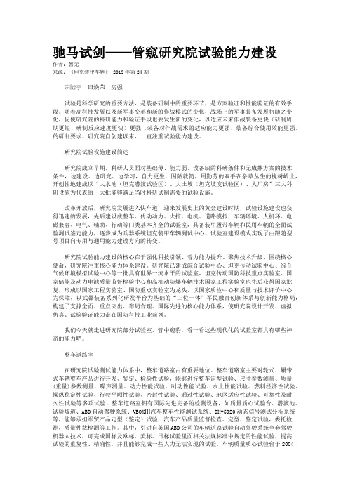
驰马试剑——管窥研究院试验能力建设作者:暂无来源:《坦克装甲车辆》 2019年第24期宗陆宇田焕荣房强试验是科学研究的重要方法,是装备研制中的重要环节,是方案验证和性能验证的有效手段。
随着高科技发展以及新军事变革和新的作战模式的变化,战场上的军事装备发展将随之变化,促使研究院的科研能力和验证手段也要发生新的变化,以适应未来作战装备更快(研制周期更短、研制反应速度更快)更强(装备对作战需求的适应能力更强、装备综合使用效能更强)的研制要求。
研究院自创建以来,一直注重试验能力建设。
研究院试验设施建设简述研究院成立早期,科研人员面对基础薄、能力弱、设备缺的科研条件和无成熟方案的技术条件,边建设、边研究、边学习,自力更生,因陋就简,用勤劳的双手在杂草丛生的槐树岭上,开创性地建成以“大水池(坦克潜渡试验区)、大土坡(坦克坡度试验区)、大厂房”三大科研设施为代表的一大批能够满足当时科研试制需要的试验设施。
改革开放后,研究院发展进入快车道,迎来发展史上的黄金建设时期,试验设施建设也获得迅速的发展,先后建设成整车、传动动力、火控、电机、道路模拟、车辆环境、人机环、电磁兼容、电气、辅助、行动等门类基本齐全的试验室,具备装甲履带车辆和民用车辆的全面试验测试鉴定能力,逐步成为兵器系统坦克装甲车辆测试中心。
试验室建设模式实现了由跟随型号项目向专用与通用能力建设方向的转变。
研究院试验能力建设的核心在于强化科技引领、着力能力提升、聚焦技术升级,围绕核心使命,研究院注重核心能力体系建设。
研究院已建成综合试验中心、坦克传动试验中心、综合气候环境模拟试验中心等一批具有世界一流水平的试验室,坦克传动国防科技重点实验室、国家储能及动力电池质量监督检验中心和高机动防爆车辆技术国家工程实验室也先后获得国家批复,形成以国家工程实验室、国防重点实验室为龙头,以国家质检中心和质量与技术评价中心为保障,以武器装备系列化研发平台为基础的“三位一体”军民融合创新体系与创新能力格局,构建了支撑全面、重点突出、布局合理、国际先进的核心能力体系,使研究院设计开发、虚拟仿真、试验验证能力走在国防科技工业前列。
履带车辆的转向理论

履带车辆的转向理论一、双履带车辆的转向理论对于双履带式车辆各种转向机构就基本原理来说是相同的,都是依靠改变两侧驱动轮上的驱动力,使其达到不同时速来实现转向的。
(一)双履带式车辆转向运动学履带车辆不带负荷,在水平地段上绕转向轴线O 作稳定转向的简图,如图7-12所示。
从转向轴线O 到车辆纵向对称平面的距离R ,称为履带式车辆的转向半径。
以T O 代表轴线O 在车辆纵向对称平面上的投影,T O 的运动速度v '代表车辆转向时的平均速度。
则车辆的转向角速度Z ω为:图7-12 履带式车辆转向运动简图R v Z '=ω (7-37)转向时,机体上任一点都绕转向轴线O 作回转,其速度为该点到轴线O 的距离和角速度Z ω的乘积。
所以慢、快速侧履带的速度1v '和2v '分别为:Z Z Z Z B v B R v B v B R v ωωωω5.0)5.0(5.0)5.0(21+'=+='-'=-=' (7-38)式中:B —履带车辆的轨距。
根据相对运动原理,可以将机体上任一点的运动分解成两种运动的合成:(1)牵连运动,;(2)相对运动。
由上可得:B R B R v v 5.05.021+-=''(二)双履带式车辆转向动力学 1、牵引平衡和力矩平衡图7-13给出了带有牵引负荷的履带式车辆,在水平地段上以转向半径R 作低速稳定转向时的受力情况(离心力可略去不计)。
转向行驶时的牵引平衡可作两点假设:(1) 在相同地面条件下,转向行驶阻力等于直线行驶阻 力,且两侧履带行驶阻力相等,即:ff f F F F 5.021='='(2)在相同的地面条件和负荷情况下,γcos x F 相当于直 线行驶的有效牵引力KP F ,即:图7-13 转向时作用在履带车辆上的外力γcos x KP F F =所以回转行驶的牵引平衡关系为:K KP f K Kx f f K KF F F F F F F F F F =+='+'+'+'='+'212121cos γ (7-39)设履带车辆回转行驶时,地面对车辆作用的阻力矩为μM ,在负荷xF 作用下总的转向阻力矩为:γμsin x T C F a M M += (7-40)式中:T a —牵引点到轴线21O O 的水平距离。
履带式牵引车和运输车
发动机
生产公司 福特(Ford)公司
型号 2658E V-6
类型 水冷柴油机
功率/转速 100kW(136马力)/5200r/min
也能安装梅塞德斯(Mercedes)5缸直列
涡式增压柴油机,91.9kW(125马力)/4500r/min
传动装置生产公司 戴姆源自-奔驰(Daimler-Benz)
该车由两节车厢组成,车身之间用转向装置连接。每1节车厢由底盘和车身组成。底盘部分由中央梁、侧传动和行动装置总成组成。4个独立的行动装置总成可互相 替换。前车厢内可戴货600kg或容纳5名士兵和1名驾驶员;后车厢可载货1400kg或有可载11名全副武装士兵的足够空间。他们的座位在车厢两旁及前 面,背囊等物可放在车顶,最重可达200kg。该车满载时可拖1辆总重为2.5t的拖车在任何道路环境下行驶,后车厢可轻易地更换以作特殊用途。
生产单位
赫格隆和桑纳公司车辆分部
AB Haegglund and Soener Vehicle Division,SE
现状
生产
装备情况
芬兰、联邦德国(1985年交付12辆)、挪威(200辆)、美国(1983~1984年交付318辆)、英国、意大利、加拿大
该车系Bandvagn 206的简称,是一种多用途的全地形运输车,能在包括雪地、沼泽等所有地形上行驶,主要用于输送战斗人员和物资。
由基型车的前后车厢改进而成。后车厢内设有1台VHF和3台UHF收发报机,可由前车厢进行操纵。前车厢内除有驾驶员外,还可搭乘1名指挥员、1名指挥员助手和1名无线电操作员;后车厢内可搭乘6名操作人员。
该车基本上系自行反坦克炮,只是还装备了1套重型反坦克导弹系统,如陶式导弹系统。大部分弹药都存放在密封的后车厢内。
- 1、下载文档前请自行甄别文档内容的完整性,平台不提供额外的编辑、内容补充、找答案等附加服务。
- 2、"仅部分预览"的文档,不可在线预览部分如存在完整性等问题,可反馈申请退款(可完整预览的文档不适用该条件!)。
- 3、如文档侵犯您的权益,请联系客服反馈,我们会尽快为您处理(人工客服工作时间:9:00-18:30)。
全地形铰接式履带车辆转向与俯仰运动性能研究全地形铰接式履带车因其具有较大的承载能力、高机动性能、较强的越野能力等优点,被广泛地应用于军事战略物资的运输、农业/林业运输、抢险救灾、森林消防等各个工程领域,为国民经济建设与国防安全建设作出了突出的贡献。
虽然世界各国相继地研制出不同类型的全地形铰接式履带车,如:瑞典“BV206”系列全地形铰接式履带车、俄罗斯“勇士”系列全地形铰接式履带车、中国“蟒式”全地形铰接式履带车等。
但是目前全地形铰接式履带车的相关基础性理论研究还处于严重的滞后状态,特别是全地形铰接式履带车行驶力学方面的研究工作最为突出。
因此研究全地形铰接式履带车行驶力学对促进全地形铰接式履带车的发展具有重要的现实意义。
行驶转向性能作为评价全地形铰接式履带车机动性的一个重要指标,也是全地形铰接式履带车行驶力学的重要组成部分。
然而现有方法大多数集中研究单履带车的转向性能,仅有的少数关于分析全地形铰接式履带车转向性能的研究方法大多数没有考虑离心力对车辆转向性能的影响,且均是以履带-土壤之间的库伦摩擦阻力为基础建立的车辆转向动力学模型,这样履带与土壤之间的摩擦系数需要通过土壤的“pull–slip”试验才能获得,从而影响了模型的通用性。
对此,本文在考虑离心力对车辆转向性能的影响下基于土壤剪切应力建立全地形铰接式履带车行驶转向动力学模型,这样模型中的相关参数可以通过现有的参考文献获得,不需要通过任何的土壤“pull–slip”试验获得,从而提高了模型的通用性,弥补了现有方法的不足,使得分析结果更加贴近工程实际。
全地形铰接式履带车通常会遇到一些小弯道的行驶路况,此时车辆需要依靠原地转向运动才能顺利通过此类路况,因此在全面评价全地形铰接式履带车通过性时需要对车辆的原地转向性能进行研究。
然而目前国内外相关的研究工作大多数集中于分析车辆的行驶转向性能,针对全地形铰接式履带车原地转向性能的研究较少。
对此本文采用数学建模的方法对全地形铰接式履带车原地转向运动过程中的运动学与动力学进行建模,并应用所建模型对某一具体车型的原地转向运动性能进行了分析,该方法可以弥补现有关于全地形铰接式履带车原地转向运动性能研究的不足。
俯仰运动作为全地形铰接式履带车特有的运动形式,它可以辅助全地形铰接式履带车通过一些极其复杂
的路况,如:壕沟、垂直障碍等。
然而现有方法大多数集中研究车辆的转向运动性能,较少关注车辆的俯仰运动性能。
对此本文在分析全地形铰接式履带车俯仰运动机理的基础上,对全地形铰接式履带车俯仰运动过程中的运动学与动力学进行建模,得到计算前后车体俯仰角度范围、前后车体的最大俯仰高度、车辆俯仰运动时前后车体重心的移动距离以及顺利完成俯仰运动时俯仰液压缸所需要提供的最小拉力/推力等的理论公式,该方法可以弥补现有关于全地形铰接式履带车俯仰运动性能研究的不足。
虚拟样机仿真技术是当今用于研究履带行走系统动力学特性的常用方法,全地形铰接式履带车是一个复杂系统,涉及传统机械系统、液压控制系统以及电气系统等,所以难以采用单一仿真软件对其进行建模仿真分析。
对此本文采用多体动力学仿真软件Recurdyn与AMESim软件建立全地形铰接式履带车的机械-控制联合仿真模型,多体动力学仿真软件Recurdyn主要构建全地形铰接式履带车的机械运动系统,而AMESim软件主要构建全地形铰接式履带车的液压控制系统。
针对全地形铰接式履带车的行驶转向运动、原地转向运动以及俯仰运动等典型工况进行虚拟样机仿真分析,并将仿真值与相应的理论值进行对比,结果表明:两者的变化趋势相一致,且两者的相对误差均未超过14.7%,这说明仿真结果与理论计算结果是相互一致的。
最后采用某一企业生产制造的全地形铰接式履带车对行驶转向运动、原地转向运动以及俯仰运动等三种典型运动工况进行了实车测试实验研究,并将实测得到的实验值与理论计算值进行了对比分析,对比结果表明:理论计算结果与实车测试结果是相互一致的,从而验证了本文所提理论模型的正确性。
本文所提出的理论方法可以为今后全地形铰接式履带车的结构设计与优化、行驶性能评价以及促进全地形铰接式履带车行驶力学的发展等具有一定的现实意义。