RS422数字隔离器IL422
RS-422标准

RS-422标准
RS-422标准全称是“平衡电压数字接口电路的电气特性”,它定义了接口电路的特性。
实际上还有一根信号地线,共5根线。
由于接收器采用高输入阻抗和发送驱动器比RS232更强的驱动能力,故允许在相同传输线上连接多个接收节点,最多可接10个节点。
即一个主设备(Master),其余为从设备(Salve),从设备之间不能通信,所以RS-422支持点对多的双向通信。
接收器输入阻抗为4k,故发端最大负载能力是10×4k+100Ω(终接电阻)。
RS-422四线接口由于采用单独的发送和接收通道,因此不必控制数据方向,各装置之间任何必须的信号交换均可以按软件方式(XON/XOFF握手)或硬件方式(一对单独的双绞线)。
RS-422的最大传输距离为4000英尺(约1219米),最大传输速率为10Mb/s。
其平衡双绞线的长度与传输速率成反比,在100kb/s 速率以下,才可能达到最大传输距离。
只有在很短的距离下才能获得最高速率传输。
一般100米长的双绞线上所能获得的最大传输速率仅为1Mb/s。
RS-422需要一终接电阻,要求其阻值约等于传输电缆的特性阻抗。
在矩距离传输时可不需终接电阻,即一般在300米以下不需终接电阻。
终接电阻接在传输电缆的最远端。
rs422波特率与传输距离
rs422波特率与传输距离摘要:1.RS422 简介2.RS422 的波特率3.RS422 的传输距离4.RS422 的优缺点5.RS422 的应用领域正文:1.RS422 简介RS422 是一种串行通信接口标准,由美国电子工业协会(Electronic Industries Alliance,EIA)制定。
RS422 是一种差分信号传输方式,它使用两根数据线进行数据传输,分别是A 和B。
A 和B 线之间的电压差表示数据的逻辑状态,这种传输方式能有效抵抗外部干扰,提高通信的可靠性。
2.RS422 的波特率RS422 的波特率是指每秒钟传输的比特数,单位为比特/秒(bps)。
RS422 的波特率可以在10bps 至1Mbps 之间选择,但常用的波特率为9600bps、19200bps、38400bps、57600bps 和115200bps。
波特率的选择取决于通信双方的硬件和实际应用需求。
波特率越高,传输速率越快,但同时也可能导致信号传输距离缩短。
3.RS422 的传输距离RS422 的传输距离受到波特率、电缆类型和噪声环境等因素的影响。
在理想的情况下,RS422 的传输距离可以达到1200 米。
然而,在实际应用中,受到电缆损耗、信号衰减和噪声等因素的影响,实际的传输距离可能会有所减少。
为了保证通信的可靠性,通常需要在传输线路上增加中继器或者采用更高质量的电缆。
4.RS422 的优缺点RS422 具有以下优点:(1)抗干扰能力强:采用差分传输方式,能有效抵抗外部干扰。
(2)传输距离较远:在理想条件下,传输距离可以达到1200 米。
(3)传输速率可调:波特率可以在10bps 至1Mbps 之间选择,满足不同应用需求。
(4)支持多机通信:RS422 允许在一条总线上连接多个设备,实现多机通信。
RS422 的缺点主要有:(1)成本较高:相较于单根数据线的串行通信接口,RS422 的硬件成本较高。
(2)传输线路要求较高:为了保证通信质量,需要使用较高质量的电缆,并在长距离传输时增加中继器。
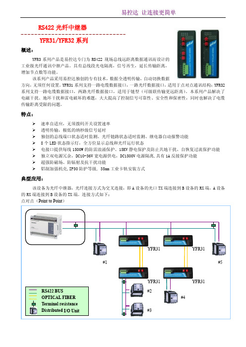
RS422总线光纤中继器用户手册
YFR31
YFR31 #2 #3
YFR31 #5
YFR31 #4
链型(Line)
易易控控达达 让让连连接接更更简简单单
RS422 BUS OPTICAL FIBER Terminal resistance Distributed I/O Unit
星型(Star)
YFR31 #1
YFR32 #2
YFR32 #3
YFR31 #4
YFR32
YFR32 #1
YFR32 #2
YFR31 #3
RS422 BUS OPTICAL FIBER Terminal resistance Distributed I/O Unit
YFR32 #4
YFR32 #5
YFR32 #6
YFR31 #7
技术参数
电接口 接口类型:5PIN 接线端子,管脚定义符合 RS422 协议规范 通信速率:0~6Mbit/S,速率自适应 信号延时(电口):100ns 电接口提供每线 1500W 的防雷浪涌保护、15KV 静电保护及防止共地干扰、自恢复过流保护功能 终端电阻:本机不带终端电阻,请按需要外接 光纤接口:
-9
光线路误码率:<10 电源及保护: 工作电压:双电源冗余输入,DC10V-36V 值,典型值 DC24V 工作电流:典型值 100mA@24V 电压保护:提供 L1+/M/L2+ 反接保护 电流保护:1 A (信号短接保护) 继电器告警输出:电口故障和光纤链路故障故障告警输出,触点容量:DC30V/1A、AC120V@1A 工作环境: 操作温度:
易易控控达达 让让连连接接更更简简单单
RS422 光纤中继器
YFR31/YFR32 系列
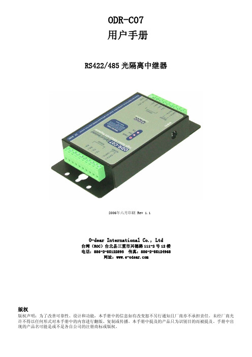
ODR-C07 RS422 485 光隔离中继器 说明书
ODR-C07用户手册RS422/485光隔离中继器2006年六月印刷 Rev 1.1O-dear International Co., Ltd台湾(ROC)台北县三重市兴德路111-2号12楼电话:886-2-85122893 传真:886-2-85124968网址:版权版权声明:为了改善可靠性、设计和功能,本手册中的信息如有改变恕不另行通知且厂商亦不承担责任。
未经厂商允许不得以任何形式对本手册中的内容进行翻版、复制或传播。
本手册中提及的产品只为识别目的而被提及。
手册中出现的产品名可能是或不是各自公司的注册商标或版权。
1.简介ODR-C07中继器用于实现对RS-422/485信号的增强使其距离扩展到最长4000 ft (1200M)并将可连接的节点数增加到高达128个。
数据格式自动检测和波特率自动切换功能使ODR-C07能够自动检测数据流从而切换数据线的方向,同时无需进行外部切换设置可自动为RS-422/485信号设置任意波特率。
光隔离提供3000VDC 的隔离以保护RS422/485数据线上的主计算机免受接地回路和破坏性电压的损坏。
各数据线上的内部过电压保护使模块免受危险电压的损坏。
1-1.特点¾自动内部RS-422/485总线管理。
¾任意輸入RS422 切換為RS485 模式.¾RS-485上的自动方向流控制。
¾支持的全波特率最高为115.2 Kbps。
¾自動傳輸資料格式切換¾支持3000 V DC電源,訊號光隔离保护。
¾RS422/485过电流保护。
¾提供 RS422/485全信号过电压保护。
¾Power/TX/RX模式 LED指示灯。
¾电源供给:支持螺旋式接线端子和标准外部DC适配器。
¾从DC +10V至+30V的电源输入要求。
1-2. 规格.¾电源输入电压:DC +10V至+30V¾输入:RS422/485协议。
RS232,RS422,RS485的区别
RS232,RS422,RS485的区别1、RS-232-CRS-232-C是美国电子工业协会EIA(Electronic Industry Association)制定的一种串行物理接口标准。
RS是英文“推荐标准”的缩写,232为标识号,C表示修改次数。
RS-232-C总线标准设有25条信号线,包括一个主通道和一个辅助通道。
在多数情况下主要使用主通道,对于一般双工通信,仅需几条信号线就可实现,如一条发送线、一条接收线及一条地线。
RS-232-C标准规定的数据传输速率为每秒50、75、100、150、300、600、1200、2400、4800、9600、19200波特。
RS-232-C标准规定,驱动器允许有2500pF的电容负载,通信距离将受此电容限制,例如,采用150pF/m的通信电缆时,最大通信距离为15m;若每米电缆的电容量减小,通信距离可以增加。
传输距离短的另一原因是RS-232属单端信号传送,存在共地噪声和不能抑制共模干扰等问题,因此一般用于20m以内的通信。
2、RS-485RS-485总线,在要求通信距离为几十米到上千米时,广泛采用RS-485 串行总线RS-485采用平衡发送和差分接收,因此具有抑制共模干扰的能力。
加上总线收发器具有高灵敏度,能检测低至200mV的电压,故传输信号能在千米以外得到恢复。
RS-485采用半双工工作方式,任何时候只能有一点处于发送状态,因此,发送电路须由使能信号加以控制。
RS-485用于多点互连时非常方便,可以省掉许多信号线。
应用RS-485可以联网构成分布式系统,其允许最多并联32台驱动器和32台接收器。
3、RS-422RS422总线,RS485和RS422电路原理基本相同,都是以差动方式发送和接受,不需要数字地线。
差动工作是同速率条件下传输距离远的根本原因,这正是二者与RS232的根本区别,因为RS232是单端输入输出,双工工作时至少需要数字地线。
rs422 rs485技术标准

一、起源和发展RS422和RS485是两种数字通信接口标准,它们分别由电子工业协会(EIA)制定。
RS422标准最早在1976年发布,而RS485标准则是在1983年发布的。
这两种标准在工业控制和数据采集系统中被广泛应用,因为它们能够提供可靠的长距离通信和抗干扰能力。
二、RS422技术特点1. RS422使用差分信号传输,能够在2000米的距离内实现数据传输,因此适用于需要远距离通信的场合。
2. RS422支持全双工通信,即可以同时进行发送和接收操作,这使得它可以在工业控制系统中进行可靠的数据传输。
3. RS422能够同时连接多个设备,因此在多点通信的场合下具有优势。
4. RS422的传输速率可以达到10Mbps,足够满足工业控制系统对高速数据传输的需求。
三、RS485技术特点1. RS485同样使用差分信号传输,能够在1200米的距离内进行数据传输,因此也适用于远距离通信的场合。
2. RS485同样支持全双工通信,因此在工业控制系统中同样具有可靠的数据传输能力。
3. RS485同样能够同时连接多个设备,因此也适用于多点通信的场合。
4. RS485的传输速率可以达到10Mbps,与RS422相比并无明显差异,同样足够满足工业控制系统对高速数据传输的需求。
四、RS422和RS485的比较1. RS422和RS485在通信距离和传输速率上几乎没有明显差异,都能够满足工业控制系统的需求。
2. RS422和RS485相比RS232更具抗干扰能力,因此更适用于工业环境中的数据传输。
3. RS485在多点通信的场合下具有优势,适用于多个设备同时进行通信的情况。
4. RS422和RS485的最大区别在于RS422支持全双工通信,而RS485支持半双工通信。
因此在实际应用中需要根据通信需求选择合适的标准。
五、RS422和RS485在工业控制系统中的应用1. 工业控制系统通常需要远距离数据传输和抗干扰能力,因此RS422和RS485成为了理想的通信接口标准。
IL422E中文资料
VI
(separately or common mode)
VIC
High-Level Digital Input Voltage
VIH
Low-Level Digital Input Voltage
VIL
Differential Input Voltage (2)
VID
High-Level Output Current (Driver)
ITU Recommended V11 • −40°C to +85°C Temperature Range • PROFIBUS International Component Recognition • 16-pin SOIC Package • UL1577 and IEC 61010-2001 Approval
Parameters Maximum Data Rate Differential Output Prop Delay Pulse Skew(10) Differential Output Rise & Fall Time Output Enable Time to High Level Output Enable Time to Low Level Output Disable Time from High Level Output Disable Time from Low Level Skew Limit(3)
Model
Package
IL422
0.3" SOIC
Pollution Degree II
UL 1577
Component Recognition Pprogram File Number: E207481 Rated 2500VRMS for 1 minute (SOIC)
基于FPGA设计的RS422-ARINC429通讯模块及软件

基于FPGA设计的RS422-ARINC429通讯模块及软件作者:奥林普科技原创出品:一、FPGA介绍FPGA(Field-Programmable Gate Array),即现场可编程门阵列,它是在PAL、GAL、CPLD等可编程器件的基础上进一步发展的产物。
它是作为专用集成电路(ASIC)领域中的一种半定制电路而出现的,既解决了定制电路的不足,又克服了原有可编程器件门电路数有限的缺点。
FPGA采用了逻辑单元阵列LCA(Logic Cell Array)这样一个概念,内部包括可配置逻辑模块CLB(Configurable Logic Block)、输出输入模块IOB(Input Output Block)和内部连线(Interconnect)三个部分。
现场可编程门阵列(FPGA)是可编程器件。
与传统逻辑电路和门阵列(如PAL,GAL及CPLD器件)相比,FPGA具有不同的结构,FPGA利用小型查找表(16×1RAM)来实现组合逻辑,每个查找表连接到一个D触发器的输入端,触发器再来驱动其他逻辑电路或驱动I/O,由此构成了即可实现组合逻辑功能又可实现时序逻辑功能的基本逻辑单元模块,这些模块间利用金属连线互相连接或连接到I/O模块。
FPGA的逻辑是通过向内部静态存储单元加载编程数据来实现的,存储在存储器单元中的值决定了逻辑单元的逻辑功能以及各模块之间或模块与I/O间的联接方式,并最终决定了FPGA所能实现的功能, FPGA允许无限次的编程。
二、RS422介绍RS-422标准全称是“平衡电压数字接口电路的电气特性”,它定义了接口电路的特性。
实际上还有一根信号地线,共5根线。
由于接收器采用高输入阻抗和发送驱动器比RS232更强的驱动能力,故允许在相同传输线上连接多个接收节点,最多可接10个节点。
即一个主设备(Master),其余为从设备(Salve),从设备之间不能通信,所以RS-422支持点对多的双向通信。
全面解析RS RS RS 的本质区别
全面解析RS232 RS422 RS485的本质区别一、串口简介RS-232、RS-422与RS-485都是串行数据接口标准,最初都是由电子工业协会(EIA)制订并发布的,RS-232在1962年发布,命名为EIA-232-E,作为工业标准,以保证不同厂家产品之间的兼容。
RS-422由RS-232发展而来,它是为弥补RS-232之不足而提出的。
为改进RS-232通信距离短、速率低的缺点,RS-422定义了一种平衡通信接口,将传输速率提高到10Mb/s,传输距离延长到4000英尺(速率低于 100kb/s时),并允许在一条平衡总线上连接最多10个接收器。
RS-422是一种单机发送、多机接收的单向、平衡传输规范,被命名为TIA/EIA-422-A标准。
为扩展应用范围,EIA又于1983年在RS-422基础上制定了RS-485标准,增加了多点、双向通信能力,即允许多个发送器连接到同一条总线上,同时增加了发送器的驱动能力和冲突保护特性,扩展了总线共模范围,后命名为TIA/EIA-485-A标准。
由于EIA提出的建议标准都是以“RS”作为前缀,所以在通讯工业领域,仍然习惯将上述标准以RS作前缀称谓。
RS-232、RS-422与RS-485标准只对接口的电气特性做出规定,而不涉及接插件、电缆或协议,在此基础上用户可以建立自己的高层通信协议。
因此在视频界的应用,许多厂家都建立了一套高层通信协议,或公开或厂家独家使用。
如录像机厂家中的Sony与松下对录像机的RS-422控制协议是有差异的,视频服务器上的控制协议则更多了,如Louth、Odetis协议是公开的,而ProLINK则是基于Profile上的。
二、RS-232串行接口标准目前RS-232是PC机与通信工业中应用最广泛的一种串行接口。
RS-232被定义为一种在低速率串行通讯中增加通讯距离的单端标准。
RS-232采取不平衡传输方式,即所谓单端通讯。
收、发端的数据信号是相对于信号地,如从DTE设备发出的数据在使用DB25连接器时是2脚相对7脚(信号地)的电平。
RS422、RS485转光纤_光猫使用说明书分享

RS23、RS422、RS485转光纤_光猫使用说明(工业级)一、概述天津三格电子的MS-F155是多功能的支持异步RS-232,RS-485,RS-422通信接口的光纤模块,可以延长RS232、RS422、RS485通信距离,最远可以达到20公里到40公里。
采用光信号传输,模块有很好的抗电磁干扰能力。
防雷设计,可用于比较恶劣的工矿环境。
支持RS-232,RS-485,RS-422多种异步通信协议,可以同时混合使用两个RS-232,4路RS-485或2路RS-422接口,支持2线(半双工)RS-485和4线(全双工)RS-422工作方式。
RS-232信号的传输速率最高为115.2Kbps,RS-485/RS-422的信号传输速率最高可达500Kbps,不同电气标准的接口可以混合使用,可以用RS-232的设备去连接RS-485/RS-422的设备,可以代替RS-232到RS-485/422接口转换器或光电隔离器,并提供了优良的EMI/RFT特性。
RS485接口采用零延迟转换时间技术、自动侦测数据流向的流控技术,使模块使用非常简单。
二、规格与特性电源:宽电源供电,7-24V直流电源。
接口:RS232/RS422/RS485。
可以同时传输2路RS232,4路485或者2路422。
传输速率:RS232可以达到115200bps;RS422 RS485可以达到400Kbps。
通信方式:RS232RS422为全双工/ RS485为半双工。
通信距离:多模可以达到2000米,单模可以达到20-40公里。
光纤:SC、LC可选口,单模,单双纤可选,1310nm、1550nm可选。
保护:15KV静电保护,1600W浪涌保护环境温度:-40---60°C存储温、湿度:-20---50°C 5%---90%体积:长120mm 宽85mm 高25mm四、LED指示灯RS485_1_LED:闪烁表示RS485_1有数据收发;RS485_2_LED:闪烁表示RS485_2有数据收发;RS485_3_LED:闪烁表示RS485_3有数据收发;RS485_4_LED:闪烁表示RS485_4有数据收发;RS232_1_LED:闪烁表示RS232_1有数据收发;RS232_2_LED:闪烁表示RS232_2有数据收发;PWR_LED:灯亮表示电源工作;Fiber_LED:灯亮表示光纤模块工作正常;五、光纤参数单模、SC口(可选择其他接口,LC FC等)、单双纤可选,波长1310nm。
高可靠性隔离型RS422接口的设计方案

在我们开发的分布式监测系统中,传感器节点需要尽可能将信号无失真稳定可靠得传 输到接入节点。从通信的可靠性考虑我们放弃了布点灵活方便的无线通信方式,选择了有线 通信。考虑到实际的应用情况,传感器需要分布在监测范围的各个角落,各个传感器与接入 节点直接的通信距离不一,从几米到上百米均有可能。如果传感器和接入节点直接选用模拟 信号直接传输的方式,对于那些传输距离远的传感器节点,其信号衰减会很严重,信噪比会 降低很多,同时传输过程中也会引入干扰,因此传感器节点需要将采集到的信号数字化,然 后通过数字接口将信号发送出去。由于数字信号抗干扰性强,可以无失真的传输,因此信号 失真只存在传感器对其数字化的过程中。有线数字通信的方式比较多,如果采用并行数据总 线,那么传感器节点和接入节点之间的连线数量会较串行总线大大增加,会给布点带来不便 和增加成本,因此在工程上长距离通信时一般都采用串行通信。由于分布式监测系统中传感 器节点和接入节点之间的通信对传输距离有一定要求,对可靠性要求高,但对通信速率要求 不高,最后我们选用了实现简单、抗干扰性强、通信距离远的RS422接口。虽然RS422采用的 是差分传输方式,抗干扰能力强,但如果只是简单的采用一般的设计方案,在温湿度及电磁 环境十分恶劣的工业环境下仍会出现接口故障甚至损坏,因此有必要从软硬件上面引入更多 的抗干扰、保护、侦错等措施来提高接口的可靠性。
编码器中的RS422

编码器中的RS422是什么意思悬赏分:0 |解决时间:2007-11-2 11:34 |提问者:zzj8288最佳答案RS422是是信号接口长线驱动型(Line Drive)此电路电源电压为DC5V,为TTL电平输出,与国际标准RS422接口直接兼容。
由于带有对称负信号的连接,电流对于电缆贡献的电磁场抵消为0,此状况衰减最小,抗干扰最佳,反应时间较短,又可传输较远的距离。
一、什么是RS-232 接口?(1) RS-232 的历史和作用在串行通讯时,要求通讯双方都采用一个标准接口,使不同的设备可以方便地连接起来进行通讯。
RS-232-C接口(又称EIA RS-232-C)是目前最常用的一种串行通讯接口。
(“RS-232-C”中的“-C”只不过表示RS-232的版本,所以与“RS-232”简称是一样的)它是在1970 年由美国电子工业协会(EIA)联合贝尔系统、调制解调器厂家及计算机终端生产厂家共同制定的用于串行通讯的标准。
它的全名是"数据终端设备(DTE)和数据通讯设备(DCE)之间串行二进制数据交换接口技术标准"该标准规定采用一个25 个脚的DB-25 连接器,对连接器的每个引脚的信号内容加以规定,还对各种信号的电平加以规定。
后来IBM的PC 机将RS-232 简化成了DB-9 连接器,从而成为事实标准。
而工业控制的RS-232 口一般只使用RXD、TXD、GND 三条线。
(2)RS-232 接口的电气特性在RS-232-C 中任何一条信号线的电压均为负逻辑关系。
即:逻辑"1"为-3 到-15V;逻辑"0"为+3 到+15V 。
RS-232-C 最常用的9 条引线的信号内容如下所示DB-9 1 2 3 4 5 6 7 8 9DB-25 8 3 2 20 7 6 4 5 22定义DCD RXD TXD DTR GND DSR RTS CTS RI(3) RS-232 接口的物理结构RS-232-C 接口连接器一般使用型号为DB-9 插头座,通常插头在DCE端,插座在DTE端.PC 机的RS-232 口为9 芯针插座。
422接线详解之欧阳索引创编

一、RS-232、RS-422与RS-485的由来欧阳家百(2021.03.07)RS-232、RS-422与RS-485都是串行数据接口标准,最初都是由电子工业协会(EIA)制订并发布的,RS-232在1962年发布,命名为EIA-232-E,作为工业标准,以保证不同厂家产品之间的兼容。
RS-422由RS-232发展而来,它是为弥补RS-232之不足而提出的。
为改进RS-232通信距离短、速率低的缺点,RS-422定义了一种平衡通信接口,将传输速率提高到10Mb/s,传输距离延长到4000英尺(速率低于100kb/s时),并允许在一条平衡总线上连接最多10个接收器。
RS-422是一种单机发送、多机接收的单向、平衡传输规范,被命名为TIA/EIA-422-A标准。
为扩展应用范围,EIA又于1983年在RS-422基础上制定了RS-485标准,增加了多点、双向通信能力,即允许多个发送器连接到同一条总线上,同时增加了发送器的驱动能力和冲突保护特性,扩展了总线共模范围,后命名为TIA/EIA-485-A标准。
由于EIA提出的建议标准都是以“RS”作为前缀,所以在通讯工业领域,仍然习惯将上述标准以RS作前缀称谓。
RS-232、RS-422与RS-485标准只对接口的电气特性做出规定,而不涉及接插件、电缆或协议,在此基础上用户可以建立自己的高层通信协议。
因此在视频界的应用,许多厂家都建立了一套高层通信协议,或公开或厂家独家使用。
如录像机厂家中的Sony与松下对录像机的RS-422控制协议是有差异的,视频服务器上的控制协议则更多了,如Louth、Odetis协议是公开的,而ProLINK则是基于Profile上的。
二、RS-232串行接口标准目前RS-232是PC机与通信工业中应用最广泛的一种串行接口。
RS-232被定义为一种在低速率串行通讯中增加通讯距离的单端标准。
RS-232采取不平衡传输方式,即所谓单端通讯。
422接线详解
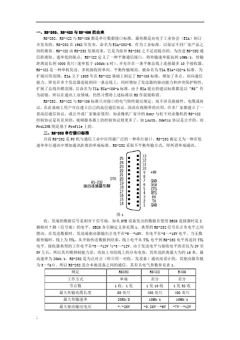
一、RS-232、RS-422与RS-485的由来RS-232、RS-422与RS-485都是串行数据接口标准,最初都是由电子工业协会(EIA)制订并发布的,RS-232在1962年发布,命名为EIA-232-E,作为工业标准,以保证不同厂家产品之间的兼容。
RS-422由RS-232发展而来,它是为弥补RS-232之不足而提出的。
为改进RS-232通信距离短、速率低的缺点,RS-422定义了一种平衡通信接口,将传输速率提高到10Mb/s,传输距离延长到4000英尺(速率低于100kb/s时),并允许在一条平衡总线上连接最多10个接收器。
RS-422是一种单机发送、多机接收的单向、平衡传输规范,被命名为TIA/EIA-422-A标准。
为扩展应用范围,EIA又于1983年在RS-422基础上制定了RS-485标准,增加了多点、双向通信能力,即允许多个发送器连接到同一条总线上,同时增加了发送器的驱动能力和冲突保护特性,扩展了总线共模范围,后命名为TIA/EIA-485-A标准。
由于EIA提出的建议标准都是以“RS”作为前缀,所以在通讯工业领域,仍然习惯将上述标准以RS作前缀称谓。
RS-232、RS-422与RS-485标准只对接口的电气特性做出规定,而不涉及接插件、电缆或协议,在此基础上用户可以建立自己的高层通信协议。
因此在视频界的应用,许多厂家都建立了一套高层通信协议,或公开或厂家独家使用。
如录像机厂家中的Sony与松下对录像机的RS-422控制协议是有差异的,视频服务器上的控制协议则更多了,如Louth、Odetis协议是公开的,而ProLINK则是基于Profile上的。
二、RS-232串行接口标准目前RS-232是PC机与通信工业中应用最广泛的一种串行接口。
RS-232被定义为一种在低速率串行通讯中增加通讯距离的单端标准。
RS-232采取不平衡传输方式,即所谓单端通讯。
图1收、发端的数据信号是相对于信号地,如从DTE设备发出的数据在使用DB25连接器时是2脚相对7脚(信号地)的电平,DB25各引脚定义参见图1。
- 1、下载文档前请自行甄别文档内容的完整性,平台不提供额外的编辑、内容补充、找答案等附加服务。
- 2、"仅部分预览"的文档,不可在线预览部分如存在完整性等问题,可反馈申请退款(可完整预览的文档不适用该条件!)。
- 3、如文档侵犯您的权益,请联系客服反馈,我们会尽快为您处理(人工客服工作时间:9:00-18:30)。
mA
mA
85
°C
kV/μs
DC Stable
Test Conditions
VDD1 = 3.3 V VDD1 = 5.0 V
Insulation Specifications
Parameters Creepage Distance Barrier Impedance Leakage Current
Safetyy or common mode)
VIC
High-Level Digital Input Voltage
VIH
Low-Level Digital Input Voltage
VIL
Differential Input Voltage(2)
VID
High-Level Output Current (Driver)
IL422
Driver Section
Electrical specifications are Tmin to Tmax and VDD = 4.5 V to 5.5 V unless otherwise stated.
Parameters
Symbol
Min.
Typ.(5)
Input Clamp Voltage
Units °C °C V V V V
mW
mA °C kV
Test Conditions
25°C 85°C 10 sec. HBM
Recommended Operating Conditions
Parameters
Symbol
Supply Voltage
VDD1 VDD2
Input Voltage at any Bus Terminal
Output voltage Differential Output Voltage(2) Differential Output Voltage(2) Differential Output Voltage(2)(6)
Change in Magnitude of Differential Output Voltage(7)
High Level Input Current Low Level Input Current
VOC
Δ|VOC|
IO IIH IIL
Short-circuit Output Current
IOS
Supply Current
VDD1 = +5 V VDD1 = +3.3 V
Parameters Maximum Data Rate Differential Output Prop Delay Pulse Skew(10) Differential Output Rise & Fall Time Output Enable Time to High Level Output Enable Time to Low Level Output Disable Time from High Level Output Disable Time from Low Level Skew Limit(3)
10
ISODE applications where the state of the isolated
drive enable node needs to be monitored
11
Y
Y Bus (Drive – True)
12
Z
Z Bus (Drive – Inverse)
13
B
B Bus (Receive – Inverse)
IOH
High-Level Digital Output Current (Receiver)
IOH
Low-Level Output Current (Driver)
IOL
Low-Level Digital Output Current (Receiver)
IOL
Ambient Operating Temperature
ITU Recommended V11 • Low EMC Footprint • −40°C to +85°C Temperature Range • PROFIBUS International Component Recognition • 16-pin SOIC Package • UL1577 and IEC 61010-2001 Approved
The IL422 has current limiting and thermal shutdown features to protect against output short circuits and bus contention situations that could cause excessive power dissipation.
14
A
A Bus (Receive – True)
15
GND2 Output Power Supply Ground Return*
16
VDD2 Output Power Supply
*NOTE: Pins 2 and 8 are internally connected, as are pins 9 and 15.
5
DE Drive Enable
6
D
Data Input to Bus
7
NC No Internal Connection
8
GND1 Input Power Supply Ground Return*
9
GND2 Output Power Supply Ground Return*
Isolated DE Output for use in Profibus
Model
Package
IL422
0.3" SOIC
Pollution Degree II
UL 1577
Component Recognition Pprogram File Number: E207481 Rated 2500VRMS for 1 minute
Soldering Profile
Per JEDEC J-STD-020C, MSL=2
Applications
Multi-point or multi-drop transmission on long bus lines in noisy environments.
Description
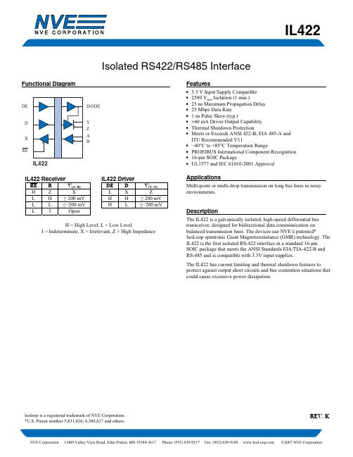
The IL422 is a galvanically isolated, high-speed differential bus transceiver, designed for bidirectional data communication on balanced transmission lines. The devices use NVE’s patented* IsoLoop spintronic Giant Magnetoresistance (GMR) technology. The IL422 is the first isolated RS-422 interface in a standard 16-pin SOIC package that meets the ANSI Standards EIA/TIA-422-B and RS-485 and is compatible with 3.3V input supplies.
IL422
Isolated RS422/RS485 Interface
Functional Diagram
DE
ISODE
D
Y
Z
R
A
B
RE
IL422
IL422 Receiver
RE R HZ
V(A−B) X
L H ≥ 200 mV
L L ≤−200 mV
L
I
Open
IL422 Driver
DE D LX HH HL
Isoloop is a registered trademark of NVE Corporation. *U.S. Patent number 5,831,426; 6,300,617 and others.
REV. Q
NVE Corporation 11409 Valley View Road, Eden Prairie, MN 55344-3617 Phone: (952) 829-9217 Fax: (952) 829-9189 ©NVE Corporation
IL422
VDD1 GND1
R
RE
DE D
NC GND1
IL422
VDD2 GND2 A B Z Y ISODE GND2
3
NVE Corporation 11409 Valley View Road Eden Prairie, MN 55344-3617 USA Telephone: (952) 829-9217 Fax (952) 829-9189 Internet:
Continuous Total Power Dissipation
Maximum Output Current Lead Solder Temperature ESD
Symbol TS TA
VDD1, VDD2
IO
Min. −65 −40 −7 −0.5 −0.5 −0.5
Typ. 2
Max. 150 100 12 7 5.5 VDD + 1 725 377 95 260
Material Group III
Max. Working Voltage 300 VRMS
