道桥专业毕业设计外文翻译----沥青路面
道桥专业外文翻译--沥青路面结构设计的低成本农村道路
外文文献structural Design of Asphalt Pavement for Low Cost Rural Roads Yuan Goulin(袁国林)1'2' Chen Rongshen(陈荣生)1. College of Transportation, Southeast University, Nanjing 210b9b, China2. College of Civil Engineering, Nanjing University of Technology, Nanjing 210009, ChinaIn developing countries,rural road construction is mostly cumbered by shortage of funds. Engineers concerns most in rural areas is how to build roads which not only cost less but also meet the traffic demands. Especially in vast rural areas of China, there are a great variety of transportation patterns, and the traffic composition is very complex. Compared with other countries,the traffic composition in China rural areas have its own features. Therefore,there is no experience about the rural roads construction for reference. In recent years,the central government of China has increased the strength for rural road construction. At the same time,a lot of researches about rural road construction have been done by researchers in China, and some conclusions about china rural roads have been made. In the authors' opinion,the selection of the pavement structure material is the key measure to reduce the construction cost of rural roads after the route has been determined. Compared with concrete pavement,asphalt pavement relatively costs less and is the first choice for rural roads in China. And then,according to the research achievements about rural roads construction,the authors have done some preliminary researches on the structure design for low-cost asphalt pavements for rural roads.1 Traffic Composition of Rural RoadRural roads include county roads,town roads and village roads.The traffic on rural roads is usually mixed. On a county road, traffic volume is between 300 to 1500 veh/d in average,and in a county with a developed economy,it reaches 1000 to 2 000 veh/d. The traffic volume between county and town is 100 to 300 veh/d,and the traffic volume between towns is usually less than 100 to 300 veh/d. In a mixed traffic flow,trucks account for 40% to 70% of the traffic volume, which are mainly light trucks carrying less than 2. 5 tons(including agricultural vehicles such as electro-tricycles,walking tractors etc.)and medium-size trucks of 2. 5 to 5 tons. Most of these light or medium trucks are overloaded. The proportion of heavy truck is less than 9%.On some roads to counties,the proportion ofoverloaded trucks is 5% to 32 %,while on some county roads connecting to national or provincial trunk highways,the proportion of overloaded vehicles usually amounts to 20% to 32% .The traffic volume on rural roads is not heavy. However,considering the practical situation in China, as well as the exitence of overloaded vehicles,100kN,or BZZ-100 was adopted as standard axle load in the research.The pavement deflection or the flexural-tensile stress at the bottom of asphalt surface is taken as the design parameter. The axle load was calculated in和-the axle weight of an i-level axle in kN and the action frequency;-the axle weight of standard axle in 100 kN and the action frequency;If the distance between axles is less than 3 m,axle loads are calculated asa double-axle or multi-axle loads,andIf the flexural-tensile stress at the bottom of semi-rigid base is taken as the design parameter, the axle load is calculated in accordance with the following formula:If the distance between axles is less than 3m,2 Traffic V olume on Rural RoadsMinibuses are adopted as the standard vehicle for the design of rural roads. Table 1 shows its external dimensions.Table 1 External dimensions of the passenger car mLength Width Height Front overhang Distance between axles Rear overhang6.0 1.8 2.0 0.8 3.8 1.4The typical vehicle types on rural roads are listed in Table 2. And others such as non-power-driven vehicles,animal-drawn vehicles,and bicycles can be taken into account in the calculation of traffic volume on rural roads,in view of their roadside interference.In accordance with the traffic composition and volumes ,rural roads are divided into five grades. The traffic volume of each grade is shown in Table 3.Traffic volume specified in Table 3 was obtained by taking the minibus as the standard vehicle type,and converting different types vehicles according to the vehicle conversion coefficients given in Table 2.In Table 3,()[]ηγγ11365-+=t s e N NNe refers to the cumulative equivalent axle load action frequency;Ns refers to the equivalent axle load action frequency in the designed traffic lane in the beginning operation period of rural roads;y refers to the average annual growth rate of traffic volume;η refers to lane coefficient, and 1.0 for a single lane and 0. 6一0. 7 for a dual lane.3 Strength of RoadbedThe modulus of resilience of roadbed varies greatly. For convenience ,the strength of roadbed can be divided into four classes according to its moisture content and modulus of resilience ,as shown in Table 4.The parameters in Table 5 are determined by combining design principles with practical experience. By applying elastic multilayer theory to the pavement structure specified in Table 5,the influence of Ne on the pavement thickness of rural roads was analyzed ,and the result show that for given h ,h2,E0,the roadbase thickness for neighboring traffic classes changes in a range of 4-5 cm. This result indicates that the classification of traffic volume on rural roads shown in Table 3 is reasonable and feasible in terms of the design and construction of asphalt pavement structures. By using the elastic multilayer theory ,the asphalt pavement structure of ordinary rural road in Table 5 is analyzed. When Ne ,the cumulative equivalent axle load action frequency ,the thickness of road surface(h =3 cm),and the thickness of subbase(h2 = 20 cm ) remain the same , the influence of neighboring roadbed strength classifications on the thickness of roadbase is 3 cm 一5 cm. This conclusion indicates that the strength classification of roadbed is reasonable and applicable to the design and construction of asphalt pavement structure.4 Determination of Thicknesses of Asphalt Pavement StructureSensitivity analysis of the design parameters of roadbed and pavement structures isto find out the relationship between structural strength of asphalt pavement structure and the design parameters of each layer, and determine the most sensitive layer in the pavement structure. The asphalt pavement structure of rural roads is generally composed of a road surface, a roadbase,and a subbase,as shown in Table 6. The pavement structure was analyzed according to elastic multiplayer theory under the double circular uniform load,with an assumption that there is continuous contact between the adjacent layers of the asphalt pavement structure. The basic parameters used in the calculation and analysis of asphalt pavement structure are listed in Table 7. By analyzing the effects of the change of all the parameters of pavement structure on the distortion of the road surface,roadbase,and roadbed , the following conclusions have been drawn.(1)Increasing the thickness of the road surface effectively decreases the road surface deflection,but raises the cost. The comparatively economical and effective method is to increase the thickness of the subbase, which is superior to increasing the thickness of roadbase,while increasing the thickness of the road surface is the last choice.(2)As the thickness of pavement structure increases,the change of road surface deflection will trend to be gentle. When the thickness of road surface reaches a certain value,the variance in the road surface deflection will not be obvious,and then it is ineffective to enhance the bearing capacity of asphalt pavement structure by increasing the thickness of road surface. It is recommended that the thicknesses of the roadbase and the subbase should be equal to or largerthan 18 and 20 cm, respectively,in design of asphalt pavement structures of rural roads. Fig. 1 shows the effects of the changes in the thickness of each layer on road surface deflection.(3)Road surface deflection is very sensitive to the change of modulus of the roadbed. The increase in the modulus of roadbase or subbase is also effective to decrease the deflection of the road surface. On the other hand,the deflection of the road surface decreases gradually when the modulus of the surface increases,being the least effective factor. When the modulus of the road surface increases to a certain value,decrease in road surface deflection is not apparent. Fig. 2 shows the effect of the modulus of each layer on road surface deflection. From the above discussion,we conclude that the most sensitive layer for road surface deflection is subbase,and the next is roadbase. To decrease the road surface deflection of low-cost rural roads,thestrength and stability of the roadbed should be enhanced, and the materials with a certain thickness and relatively high density should be used to pave the subbase.The traffic volume or the accumulative equivalent axle load action times(frequency)within the designed life of road is used to determine the type and thickness of the asphalt pavement road surface, and the results are listed in Table 8,where veh/d means the number of the equivalent the passenger cars per day.For a low traffic volume rural road with Ne 500 000,graded broken stones(or gravel)can be used as a flexible base. The flexible base has good strength and effectively prevents reflection cracks of the asphalt pavement road surface, provided the graded broken stones(or gravel ) meets the requirements for high density(degree of compaction ,100%. To ensure the sufficient strength and stability of the flexible base,its thickness is not less than 15 cm,the thickness of the aggregate subbase is not less than 20 cm,A semi-rigid base usually has a good bearing capacity For the rural roads with Ne)500 000,or those with low traffic volumes but relatively,the minimum thickness of semirigid base or subbase is 16-18 cm5 Calculation of the Thickness of Road Surface5.1 Deflection(1)Road surface deflectionRoad surface deflection is a vertical distortion caused by vertical load on the road surface. It not only reflects the whole strength and stiffness of asphalt pavement structure and roadbed,but also has a close internal relation with the service condition of the pavement.(2)Design deflectionThe design deflection is the index representing the stiffness of the pavement structure. It is also the deflection of the pavement which is established according to the accumulative equivalent axle load estimated to pass over a lane in the expected design life, road types, road classification,and the types of road surface and roadbase. The design deflection is not only the main basis for the design thickness of the pavement structure,but also the necessary index for the examination and acceptance of the project. Through theoretical analysis and experimental study,formulas for the design deflection value which are applicable to the pavement structure design of lowcost rural roads are as follows:semi-rigid base:flexible base:where A, is the type coefficient of the road surface. The type coefficient of asphalt concrete road surface is 1.0;that of hot-mix asphalt macadam and that of emulsified asphalt macadam road surface are all 1. 1; and that of asphalt surface treatment road surface is1 .2.(3)Allowable deflectionAllowable deflection is the maximum deflectionallowed at the end of the road's service life under lim-iting conditions in poor season. Through thoreticalanalysis and experimental study,the calculation for-mulas for the allowable deflection of road surfacewhich are applicable to the pavement structure designof low-cost rural roads are as follows}2}:When designing the asphalt pavement structure of low-cost rural roads, we should use formula (6) or (7 ) according to the types of roadbase to determine the thickness of asphalt pavement structure.5.2 Tensile stressBecause the asphalt pavement structure of lowcost rural roads is not substantial enough and the heavy vehicles are allowed to pass over them, the maximum tensile stress should be checked by computing the stresses of the semi-rigid base and subbase. The tensile stress at the bottom of semi-rigid base or subbase,would be less than or equivalent to the allowable tensile stress of the materials of the semirigid base or subbase , namely,For the stabilized aggregate base with an inorganic binder-For the stabilized fine-grained soil base with an inorganic binder:5.3 Pavement thicknessTo make it simple and convenient for engineers to determine the desired thickness of rural road pavement, the curves of the thickness of the roadbase of low-cost rural roads according to typical pavement structures and accumulative frequency of equivalent axle load are shown in Figs. 3,4 and 5.(1)When the accumulative frequency of equivalent axle load is within 500000 times per lane,asphalttreated or asphalt penetrated surfaces with thickness of 1. 5 cm 一cm is recommended for road surface. For various accumulative equivalent axle loads and the moduli(Eo)of roadbed,the equivalent thickness of roadbase is shown in Fig. 3.(2)When the accumulative frequency of equivalent axle load is within 500 001)一1 000 000 times per lane,asphalt macadam or asphalt concrete with thickness of 3 cm -5 cm is recommended. For various accumulative equivalent axle loads and moduli(Eo)of roadbed,the equivalent thickness of roadbase is shown in Fig. 4.(3)When the accumulative frequency of equivalent axle load is within 1000 000-2 000 000 times per lane,asphalt concrete road surface of 5 cm-7 cm thick is recommended. For various accumulative equivalent axle loads and moduli(Eo)of roadbed , the equivalent thickness of roadbase is shown in Fig.S.In Figs.3-5,Ld is the designed deflection, Lo is the representative deflection of roadbed,E, is the modulus of resilience of the roadbase,in MPa , Eo is the modulus of resilience of the roadbed,in MPa ,and H, in cm,is the equivalent thickness of the base (roadbase and subbase),which can be obtained through calculation and in-site investigation for a trilevel-pavement roads(including road surface,base and roadbed).If a designed road has four layers,i.e. a subbase is added,according to the regression analysis of the extrapolated results of a number of multi-layer flexible systems and the available research findings,the thickness of the roadbase , h,,in cm, can be calculated from the following equation:6 Concluding RemarksCompared with concrete pavement, asphalt pavements have a lowerconstruction cost, which is suitable for the roads in relatively underdeveloped rural areas in China. The research in this paper proposed a method for structural design of low cost asphalt pavements. The method is to provide an guideline for the design of asphalt pavement structure in rural areas.References[1]Yuan G L , Zhang F , Chen S W , et al. Research on technical indexes of rural highway construction in Jiangsu province [ J ].Highway, 2005(6):135一139(in Chinese).[ 2 ] Research Institute of Highway , the Ministry of Communications. Final Report on Low Cost Inter-township and Rural Road Construction Techniques 〔R].Beijing; Resdarch Institute of Highway, 2003(in Chinese).[ 3 ] Liu Q Q. How to reduce the construction cost of the rural highway [ J ] .Journal of Highway and Transportation Research and Development, 2005(2):41一44(in Chinese).[ 4 ] JTG B014-97. Specification for design of highway asphalt pavement[ S ](in Chinese ).[ 5 ] JTG BO1-2003. Technical Standard of Highway Engineering [ S ](in Chinese).[6] Deng X J. Engineering for sub-grade and pavement[ M].2nd ed. Beijing; People's Communications Press, Beijing, 2004(in Chinese ).中文译文沥青路面结构设计的低成本农村道路袁国林1,陈荣生21。
道路路桥工程中英文对照外文翻译文献

道路路桥工程中英文对照外文翻译文献Asphalt Mixtures: ns。
Theory。
and Principles1.nsXXX industry。
XXX。
The most common n of asphalt is in the n of XXX "flexible" XXX them from those made with Portland cement。
XXX2.XXXXXX the use of aggregates。
XXX。
sand。
or gravel。
and a binder。
XXX for the pavement。
XXX。
The quality of the asphalt XXX to the performance of the pavement。
as it must be able to XXX。
3.PrinciplesXXX。
with each layer XXX layers typically include a subgrade。
a sub-base。
a base course。
and a surface course。
The subgrade is the natural soil or rock upon which the pavement is built。
while the sub-base and base courses provide nal support for the pavement。
The surface course is the layer that comes into direct contact with traffic and is XXX。
In n。
the use of XXX.The n of flexible pavement can be subdivided into high and low types。
道路桥梁专业 中英文对照---毕业设计论文 外文文献翻译
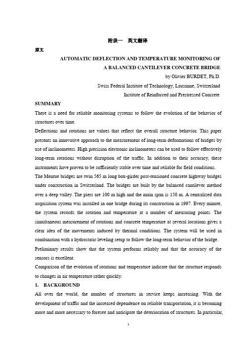
附录一英文翻译原文AUTOMATIC DEFLECTION AND TEMPERATURE MONITORING OFA BALANCED CANTILEVER CONCRETE BRIDGEby Olivier BURDET, Ph.D.Swiss Federal Institute of Technology, Lausanne, SwitzerlandInstitute of Reinforced and Prestressed Concrete SUMMARYThere is a need for reliable monitoring systems to follow the evolution of the behavior of structures over time.Deflections and rotations are values that reflect the overall structure behavior. This paper presents an innovative approach to the measurement of long-term deformations of bridges by use of inclinometers. High precision electronic inclinometers can be used to follow effectively long-term rotations without disruption of the traffic. In addition to their accuracy, these instruments have proven to be sufficiently stable over time and reliable for field conditions. The Mentue bridges are twin 565 m long box-girder post-tensioned concrete highway bridges under construction in Switzerland. The bridges are built by the balanced cantilever method over a deep valley. The piers are 100 m high and the main span is 150 m. A centralized data acquisition system was installed in one bridge during its construction in 1997. Every minute, the system records the rotation and temperature at a number of measuring points. The simultaneous measurement of rotations and concrete temperature at several locations gives a clear idea of the movements induced by thermal conditions. The system will be used in combination with a hydrostatic leveling setup to follow the long-term behavior of the bridge. Preliminary results show that the system performs reliably and that the accuracy of the sensors is excellent.Comparison of the evolution of rotations and temperature indicate that the structure responds to changes in air temperature rather quickly.1.BACKGROUNDAll over the world, the number of structures in service keeps increasing. With the development of traffic and the increased dependence on reliable transportation, it is becoming more and more necessary to foresee and anticipate the deterioration of structures. In particular,for structures that are part of major transportation systems, rehabilitation works need to be carefully planned in order to minimize disruptions of traffic. Automatic monitoring of structures is thus rapidly developing.Long-term monitoring of bridges is an important part of this overall effort to attempt to minimize both the impact and the cost of maintenance and rehabilitation work of major structures. By knowing the rate of deterioration of a given structure, the engineer is able to anticipate and adequately define the timing of required interventions. Conversely, interventions can be delayed until the condition of the structure requires them, without reducing the overall safety of the structure.The paper presents an innovative approach to the measurement of long-term bridge deformations. The use of high precision inclinometers permits an effective, accurate and unobtrusive following of the long-term rotations. The measurements can be performed under traffic conditions. Simultaneous measurement of the temperature at several locations gives a clear idea of the movements induced by thermal conditions and those induced by creep and shrinkage. The system presented is operational since August 1997 in the Mentue bridge, currently under construction in Switzerland. The structure has a main span of 150 m and piers 100 m high.2. LONG-TERM MONITORING OF BRIDGESAs part of its research and service activities within the Swiss Federal Institute of Technology in Lausanne (EPFL), IBAP - Reinforced and Prestressed Concrete has been involved in the monitoring of long-time deformations of bridges and other structures for over twenty-five years [1, 2, 3, 4]. In the past, IBAP has developed a system for the measurement of long-term deformations using hydrostatic leveling [5, 6]. This system has been in successful service in ten bridges in Switzerland for approximately ten years [5,7]. The system is robust, reliable and sufficiently accurate, but it requires human intervention for each measurement, and is not well suited for automatic data acquisition. One additional disadvantage of this system is that it is only easily applicable to box girder bridges with an accessible box.Occasional continuous measurements over periods of 24 hours have shown that the amplitude of daily movements is significant, usually amounting to several millimeters over a couple of hours. This is exemplified in figure 1, where measurements of the twin Lutrive bridges, taken over a period of several years before and after they were strengthened by post-tensioning, areshown along with measurements performed over a period of 24 hours. The scatter observed in the data is primarily caused by thermal effects on the bridges. In the case of these box-girder bridges built by the balanced cantilever method, with a main span of 143.5 m, the amplitude of deformations on a sunny day is of the same order of magnitude than the long term deformation over several years.Instantaneous measurements, as those made by hydrostatic leveling, are not necessarily representative of the mean position of the bridge. This occurs because the position of the bridge at the time of the measurement is influenced by the temperature history over the past several hours and days. Even if every care was taken to perform the measurements early in the morning and at the same period every year, it took a relatively long time before it was realized that the retrofit performed on the Lutrive bridges in 1988 by additional post-tensioning [3, 7,11] had not had the same effect on both of them.Figure 1: Long-term deflections of the Lutrive bridges, compared to deflections measured in a 24-hour period Automatic data acquisition, allowing frequent measurements to be performed at an acceptable cost, is thus highly desirable. A study of possible solutions including laser-based leveling, fiber optics sensors and GPS-positioning was performed, with the conclusion that, provided that their long-term stability can be demonstrated, current types of electronic inclinometers are suitable for automatic measurements of rotations in existing bridges [8].3. MENTUE BRIDGESThe Mentue bridges are twin box-girder bridges that will carry the future A1 motorway from Lausanne to Bern. Each bridge, similar in design, has an overall length of approximately 565 m, and a width of 13.46 m, designed to carry two lanes of traffic and an emergency lane. The bridges cross a deep valley with steep sides (fig. 2). The balanced cantilever design results from a bridge competition. The 100 m high concrete piers were built using climbing formwork, after which the construction of the balanced cantilever started (fig. 3).4. INCLINOMETERSStarting in 1995, IBAP initiated a research project with the goal of investigating the feasibility of a measurement system using inclinometers. Preliminary results indicated that inclinometers offer several advantages for the automatic monitoring of structures. Table 1 summarizes the main properties of the inclinometers selected for this study.One interesting property of measuring a structure’s rotations, is that, for a given ratio of maximum deflection to span length, the maximum rotation is essentially independent from its static system [8]. Since maximal allowable values of about 1/1,000 for long-term deflections under permanent loads are generally accepted values worldwide, developments made for box-girder bridges with long spans, as is the case for this research, are applicable to other bridges, for instance bridges with shorter spans and other types of cross-sections. This is significant because of the need to monitor smaller spans which constitute the majority of all bridges.The selected inclinometers are of type Wyler Zerotronic ±1°[9]. Their accuracy is 1 microradian (μrad), which corresponds to a rotation of one millimeter per kilometer, a very small value. For an intermediate span of a continuous beam with a constant depth, a mid-span deflection of 1/20,000 would induce a maximum rotation of about 150 μrad, or 0.15 milliradians (mrad).One potential problem with electronic instruments is that their measurements may drift overtime. To quantify and control this problem, a mechanical device was designed allowing the inclinometers to be precisely rotated of 180° in an horizontal plane (fig. 4). The drift of each inclinometer can be very simply obtained by comparing the values obtained in the initial and rotated position with previously obtained values. So far, it has been observed that the type of inclinometer used in this project is not very sensitive to drifting.5. INSTRUMENTATION OF THE MENTUE BRIDGESBecause a number of bridges built by the balanced cantilever method have shown an unsatisfactory behavior in service [2, 7,10], it was decided to carefully monitor the evolution of the deformations of the Mentue bridges. These bridges were designed taking into consideration recent recommendations for the choice of the amount of posttensioning [7,10,13]. Monitoring starting during the construction in 1997 and will be pursued after the bridges are opened to traffic in 2001. Deflection monitoring includes topographic leveling by the highway authorities, an hydrostatic leveling system over the entire length of both bridges and a network of inclinometers in the main span of the North bridge. Data collection iscoordinated by the engineer of record, to facilitate comparison of measured values. The information gained from these observations will be used to further enhance the design criteria for that type of bridge, especially with regard to the amount of post-tensioning [7, 10, 11, 12, 13].The automatic monitoring system is driven by a data acquisition program that gathers and stores the data. This system is able to control various types of sensors simultaneously, at the present time inclinometers and thermal sensors. The computer program driving all the instrumentation offers a flexible framework, allowing the later addition of new sensors or data acquisition systems. The use of the development environment LabView [14] allowed to leverage the large user base in the field of laboratory instrumentation and data analysis. The data acquisition system runs on a rather modest computer, with an Intel 486/66 Mhz processor, 16 MB of memory and a 500 MB hard disk, running Windows NT. All sensor data are gathered once per minute and stored in compressed form on the hard disk. The system is located in the box-girder on top of pier 3 (fig. 5). It can withstand severe weather conditions and will restart itself automatically after a power outage, which happened frequently during construction.6. SENSORSFigure 5(a) shows the location of the inclinometers in the main span of the North bridge. The sensors are placed at the axis of the supports (①an d⑤), at 1/4 and 3/4 (③an d④) of the span and at 1/8 of the span for②. In the cross section, the sensors are located on the North web, at a height corresponding to the center of gravity of the section (fig.5a). The sensors are all connected by a single RS-485 cable to the central data acquisition system located in the vicinity of inclinometer ①. Monitoring of the bridge started already during its construction. Inclinometers①,②and③were installed before the span was completed. The resulting measurement were difficult to interpret, however, because of the wide variations of angles induced by the various stages of this particular method of construction.The deflected shape will be determined by integrating the measured rotations along the length of the bridge (fig.5b). Although this integration is in principle straightforward, it has been shown [8, 16] that the type of loading and possible measurement errors need to be carefully taken into account.Thermal sensors were embedded in concrete so that temperature effects could be taken into account for the adjustment of the geometry of the formwork for subsequent casts. Figure 6 shows the layout of thermal sensors in the main span. The measurement sections are located at the same sections than the inclinometers (fig. 5). All sensors were placed in the formwork before concreting and were operational as soon as the formwork was removed, which was required for the needs of the construction. In each section, seven of the nine thermal sensor (indicated in solid black in fig. 6) are now automatically measured by the central data acquisition system.7. RESULTSFigure 7 shows the results of inclinometry measurements performed from the end ofSeptember to the third week of November 1997. All inclinometers performed well during that period. Occasional interruptions of measurement, as observed for example in early October are due to interruption of power to the system during construction operations. The overall symmetry of results from inclinometers seem to indicate that the instruments drift is not significant for that time period. The maximum amplitude of bridge deflection during the observed period, estimated on the basis of the inclinometers results, is around 40 mm. More accurate values will be computed when the method of determination ofdeflections will have been further calibrated with other measurements. Several periods of increase, respectively decrease, of deflections over several days can be observed in the graph. This further illustrates the need for continuous deformation monitoring to account for such effects. The measurement period was .busy. in terms of construction, and included the following operations: the final concrete pours in that span, horizontal jacking of the bridge to compensate some pier eccentricities, as well as the stressing of the continuity post-tensioning, and the de-tensioning of the guy cables (fig. 3). As a consequence, the interpretation of these measurements is quite difficult. It is expected that further measurements, made after the completion of the bridge, will be simpler to interpret.Figure 8 shows a detail of the measurements made in November, while figure.9 shows temperature measurements at the top and bottom of the section at mid-span made during that same period. It is clear that the measured deflections correspond to changes in the temperature. The temperature at the bottom of the section follows closely variations of the air temperature(measured in the shade near the north web of the girder). On the other hand, the temperature at the top of the cross section is less subject to rapid variations. This may be due to the high elevation of the bridge above ground, and also to the fact that, during the measuring period, there was little direct sunshine on the deck. The temperature gradient between top and bottom of the cross section has a direct relationship with short-term variations. It does not, however, appear to be related to the general tendency to decrease in rotations observed in fig. 8.8. FUTURE DEVELOPMENTSFuture developments will include algorithms to reconstruct deflections from measured rotations. To enhance the accuracy of the reconstruction of deflections, a 3D finite element model of the entire structure is in preparation [15]. This model will be used to identify the influence on rotations of various phenomena, such as creep of the piers and girder, differential settlements, horizontal and vertical temperature gradients or traffic loads.Much work will be devoted to the interpretation of the data gathered in the Mentue bridge. The final part of the research project work will focus on two aspects: understanding the very complex behavior of the structure, and determining the most important parameters, to allow a simple and effective monitoring of the bridges deflections.Finally, the research report will propose guidelines for determination of deflections from measured rotations and practical recommendations for the implementation of measurement systems using inclinometers. It is expected that within the coming year new sites will be equipped with inclinometers. Experiences made by using inclinometers to measure deflections during loading tests [16, 17] have shown that the method is very flexible and competitive with other high-tech methods.As an extension to the current research project, an innovative system for the measurement of bridge joint movement is being developed. This system integrates easily with the existing monitoring system, because it also uses inclinometers, although from a slightly different type.9. CONCLUSIONSAn innovative measurement system for deformations of structures using high precision inclinometers has been developed. This system combines a high accuracy with a relatively simple implementation. Preliminary results are very encouraging and indicate that the use of inclinometers to monitor bridge deformations is a feasible and offers advantages. The system is reliable, does not obstruct construction work or traffic and is very easily installed. Simultaneous temperature measurements have confirmed the importance of temperature variations on the behavior of structural concrete bridges.10. REFERENCES[1] ANDREY D., Maintenance des ouvrages d’art: méthodologie de surveillance, PhD Dissertation Nr 679, EPFL, Lausanne, Switzerland, 1987.[2] BURDET O., Load Testing and Monitoring of Swiss Bridges, CEB Information Bulletin Nr 219, Safety and Performance Concepts, Lausanne, Switzerland, 1993.[3] BURDET O., Critères pour le choix de la quantitéde précontrainte découlant de l.observation de ponts existants, CUST-COS 96, Clermont-Ferrand, France, 1996.[4] HASSAN M., BURDET O., FAVRE R., Combination of Ultrasonic Measurements and Load Tests in Bridge Evaluation, 5th International Conference on Structural Faults and Repair, Edinburgh, Scotland, UK, 1993.[5] FAVRE R., CHARIF H., MARKEY I., Observation à long terme de la déformation des ponts, Mandat de Recherche de l’OFR 86/88, Final Report, EPFL, Lausanne, Switzerland, 1990.[6] FAVRE R., MARKEY I., Long-term Monitoring of Bridge Deformation, NATO Research Workshop, Bridge Evaluation, Repair and Rehabilitation, NATO ASI series E: vol. 187, pp. 85-100, Baltimore, USA, 1990.[7] FAVRE R., BURDET O. et al., Enseignements tirés d’essais de charge et d’observations à long terme pour l’évaluation des ponts et le choix de la précontrainte, OFR Report, 83/90, Zürich, Switzerland, 1995.[8] DAVERIO R., Mesures des déformations des ponts par un système d’inclinométrie,Rapport de maîtrise EPFL-IBAP, Lausanne, Switzerland, 1995.[9] WYLER AG., Technical specifications for Zerotronic Inclinometers, Winterthur, Switzerland, 1996.[10] FAVRE R., MARKEY I., Generalization of the Load Balancing Method, 12th FIP Congress, Prestressed Concrete in Switzerland, pp. 32-37, Washington, USA, 1994.[11] FAVRE R., BURDET O., CHARIF H., Critères pour le choix d’une précontrainte: application au cas d’un renforcement, "Colloque International Gestion des Ouvrages d’Art: Quelle Stratégie pour Maintenir et Adapter le Patrimoine, pp. 197-208, Paris, France, 1994. [12] FAVRE R., BURDET O., Wahl einer geeigneten Vorspannung, Beton- und Stahlbetonbau, Beton- und Stahlbetonbau, 92/3, 67, Germany, 1997.[13] FAVRE R., BURDET O., Choix d’une quantité appropriée de précontrain te, SIA D0 129, Zürich, Switzerland, 1996.[14] NATIONAL INSTRUMENTS, LabView User.s Manual, Austin, USA, 1996.[15] BOUBERGUIG A., ROSSIER S., FAVRE R. et al, Calcul non linéaire du béton arméet précontraint, Revue Français du Génie Civil, vol. 1 n° 3, Hermes, Paris, France, 1997. [16] FEST E., Système de mesure par inclinométrie: développement d’un algorithme de calcul des flèches, Mémoire de maîtrise de DEA, Lausanne / Paris, Switzerland / France, 1997.[17] PERREGAUX N. et al., Vertical Displacement of Bridges using the SOFO System: a Fiber Optic Monitoring Method for Structures, 12th ASCE Engineering Mechanics Conference, San Diego, USA, to be published,1998.译文平衡悬臂施工混凝土桥挠度和温度的自动监测作者Olivier BURDET博士瑞士联邦理工学院,洛桑,瑞士钢筋和预应力混凝土研究所概要:我们想要跟踪结构行为随时间的演化,需要一种可靠的监测系统。
道路与桥梁工程中英文对照外文翻译文献

中英文对照外文翻译(文档含英文原文和中文翻译)Bridge research in EuropeA brief outline is given of the development of the European Union, together withthe research platform in Europe. The special case of post-tensioned bridges in the UK is discussed. In order to illustrate the type of European research being undertaken, an example is given from the University of Edinburgh portfolio: relating to the identification of voids in post-tensioned concrete bridges using digital impulse radar.IntroductionThe challenge in any research arena is to harness the findings of different research groups to identify a coherent mass of data, which enables research and practice to be better focused. A particular challenge exists with respect to Europe where language barriers are inevitably very significant. The European Community was formed in the 1960s based upon a political will within continental Europe to avoid the European civil wars, which developed into World War 2 from 1939 to 1945. The strong political motivation formed the original community of which Britain was not a member. Many of the continental countries saw Britain’s interest as being purelyeconomic. The 1970s saw Britain joining what was then the European Economic Community (EEC) and the 1990s has seen the widening of the community to a European Union, EU, with certain political goals together with the objective of a common European currency.Notwithstanding these financial and political developments, civil engineering and bridge engineering in particular have found great difficulty in forming any kind of common thread. Indeed the educational systems for University training are quite different between Britain and the European continental countries. The formation of the EU funding schemes —e.g. Socrates, Brite Euram and other programs have helped significantly. The Socrates scheme is based upon the exchange of students between Universities in different member states. The Brite Euram scheme has involved technical research grants given to consortia of academics and industrial partners within a number of the states—— a Brite Euram bid would normally be led by partners within a number of the statesan industrialist.In terms of dissemination of knowledge, two quite different strands appear to have emerged. The UK and the USA have concentrated primarily upon disseminating basic research in refereed journal publications: ASCE, ICE and other journals. Whereas the continental Europeans have frequently disseminated basic research at conferences where the circulation of the proceedings is restricted.Additionally, language barriers have proved to be very difficult to break down. In countries where English is a strong second language there has been enthusiastic participation in international conferences based within continental Europe —e.g. Germany, Italy, Belgium, The Netherlands and Switzerland. However, countries where English is not a strong second language have been hesitant participants }—e.g. France.European researchExamples of research relating to bridges in Europe can be divided into three types of structure:Masonry arch bridgesBritain has the largest stock of masonry arch bridges. In certain regions of the UK up to 60% of the road bridges are historic stone masonry arch bridges originally constructed for horse drawn traffic. This is less common in other parts of Europe as many of these bridges were destroyed during World War 2.Concrete bridgesA large stock of concrete bridges was constructed during the 1950s, 1960s and 1970s. At the time, these structures were seen as maintenance free. Europe also has a large number of post-tensioned concrete bridges with steel tendon ducts preventing radar inspection. This is a particular problem in France and the UK.Steel bridgesSteel bridges went out of fashion in the UK due to their need for maintenance as perceived in the 1960s and 1970s. However, they have been used for long span and rail bridges, and they are now returning to fashion for motorway widening schemes in the UK.Research activity in EuropeIt gives an indication certain areas of expertise and work being undertaken in Europe, but is by no means exhaustive.In order to illustrate the type of European research being undertaken, an example is given from the University of Edinburgh portfolio. The example relates to the identification of voids in post-tensioned concrete bridges, using digital impulse radar.Post-tensioned concrete rail bridge analysisOve Arup and Partners carried out an inspection and assessment of the superstructure of a 160 m long post-tensioned, segmental railway bridge in Manchester to determine its load-carrying capacity prior to a transfer of ownership, for use in the Metrolink light rail system..Particular attention was paid to the integrity of its post-tensioned steel elements.Physical inspection, non-destructive radar testing and other exploratory methods were used to investigate for possible weaknesses in the bridge.Since the sudden collapse of Ynys-y-Gwas Bridge in Wales, UK in 1985, there has been concern about the long-term integrity of segmental, post-tensioned concrete bridges which may b e prone to ‘brittle’ failure without warning. The corrosion protection of the post-tensioned steel cables, where they pass through joints between the segments, has been identified as a major factor affecting the long-term durability and consequent strength of this type of bridge. The identification of voids in grouted tendon ducts at vulnerable positions is recognized as an important step in the detection of such corrosion.Description of bridgeGeneral arrangementBesses o’ th’ Barn Bridge is a 160 m long, three span, segmental, post-tensionedconcrete railway bridge built in 1969. The main span of 90 m crosses over both the M62 motorway and A665 Bury to Prestwick Road. Minimum headroom is 5.18 m from the A665 and the M62 is cleared by approx 12.5 m.The superstructure consists of a central hollow trapezoidal concrete box section 6.7 m high and 4 m wide. The majority of the south and central spans are constructed using 1.27 m long pre-cast concrete trapezoidal box units, post-tensioned together. This box section supports the in site concrete transverse cantilever slabs at bottom flange level, which carry the rail tracks and ballast.The center and south span sections are of post-tensioned construction. These post-tensioned sections have five types of pre-stressing:1. Longitudinal tendons in grouted ducts within the top and bottom flanges.2. Longitudinal internal draped tendons located alongside the webs. These are deflected at internal diaphragm positions and are encased in in site concrete.3. Longitudinal macalloy bars in the transverse cantilever slabs in the central span .4. Vertical macalloy bars in the 229 mm wide webs to enhance shear capacity.5. Transverse macalloy bars through the bottom flange to support the transverse cantilever slabs.Segmental constructionThe pre-cast segmental system of construction used for the south and center span sections was an alternative method proposed by the contractor. Current thinkingire suggests that such a form of construction can lead to ‘brittle’ failure of the ententire structure without warning due to corrosion of tendons across a construction joint,The original design concept had been for in site concrete construction.Inspection and assessmentInspectionInspection work was undertaken in a number of phases and was linked with the testing required for the structure. The initial inspections recorded a number of visible problems including:Defective waterproofing on the exposed surface of the top flange.Water trapped in the internal space of the hollow box with depths up to 300 mm.Various drainage problems at joints and abutments.Longitudinal cracking of the exposed soffit of the central span.Longitudinal cracking on sides of the top flange of the pre-stressed sections.Widespread sapling on some in site concrete surfaces with exposed rusting reinforcement.AssessmentThe subject of an earlier paper, the objectives of the assessment were:Estimate the present load-carrying capacity.Identify any structural deficiencies in the original design.Determine reasons for existing problems identified by the inspection.Conclusion to the inspection and assessmentFollowing the inspection and the analytical assessment one major element of doubt still existed. This concerned the condition of the embedded pre-stressing wires, strands, cables or bars. For the purpose of structural analysis these elements、had been assumed to be sound. However, due to the very high forces involved,、a risk to the structure, caused by corrosion to these primary elements, was identified.The initial recommendations which completed the first phase of the assessment were:1. Carry out detailed material testing to determine the condition of hidden structural elements, in particularthe grouted post-tensioned steel cables.2. Conduct concrete durability tests.3. Undertake repairs to defective waterproofing and surface defects in concrete.Testing proceduresNon-destructi v e radar testingDuring the first phase investigation at a joint between pre-cast deck segments the observation of a void in a post-tensioned cable duct gave rise to serious concern about corrosion and the integrity of the pre-stress. However, the extent of this problem was extremely difficult to determine. The bridge contains 93 joints with an average of 24 cables passing through each joint, i.e. there were approx. 2200 positions where investigations could be carried out. A typical section through such a joint is that the 24 draped tendons within the spine did not give rise to concern because these were protected by in site concrete poured without joints after the cables had been stressed.As it was clearly impractical to consider physically exposing all tendon/joint intersections, radar was used to investigate a large numbers of tendons and hence locate duct voids within a modest timescale. It was fortunate that the corrugated steel ducts around the tendons were discontinuous through the joints which allowed theradar to detect the tendons and voids. The problem, however, was still highly complex due to the high density of other steel elements which could interfere with the radar signals and the fact that the area of interest was at most 102 mm wide and embedded between 150 mm and 800 mm deep in thick concrete slabs.Trial radar investigations.Three companies were invited to visit the bridge and conduct a trial investigation. One company decided not to proceed. The remaining two were given 2 weeks to mobilize, test and report. Their results were then compared with physical explorations.To make the comparisons, observation holes were drilled vertically downwards into the ducts at a selection of 10 locations which included several where voids were predicted and several where the ducts were predicted to be fully grouted. A 25-mm diameter hole was required in order to facilitate use of the chosen horoscope. The results from the University of Edinburgh yielded an accuracy of around 60%.Main radar sur v ey, horoscope verification of v oids.Having completed a radar survey of the total structure, a baroscopic was then used to investigate all predicted voids and in more than 60% of cases this gave a clear confirmation of the radar findings. In several other cases some evidence of honeycombing in the in site stitch concrete above the duct was found.When viewing voids through the baroscopic, however, it proved impossible to determine their actual size or how far they extended along the tendon ducts although they only appeared to occupy less than the top 25% of the duct diameter. Most of these voids, in fact, were smaller than the diameter of the flexible baroscopic being used (approximately 9 mm) and were seen between the horizontal top surface of the grout and the curved upper limit of the duct. In a very few cases the tops of the pre-stressing strands were visible above the grout but no sign of any trapped water was seen. It was not possible, using the baroscopic, to see whether those cables were corroded.Digital radar testingThe test method involved exciting the joints using radio frequency radar antenna: 1 GHz, 900 MHz and 500 MHz. The highest frequency gives the highest resolution but has shallow depth penetration in the concrete. The lowest frequency gives the greatest depth penetration but yields lower resolution.The data collected on the radar sweeps were recorded on a GSSI SIR System 10.This system involves radar pulsing and recording. The data from the antenna is transformed from an analogue signal to a digital signal using a 16-bit analogue digital converter giving a very high resolution for subsequent data processing. The data is displayed on site on a high-resolution color monitor. Following visual inspection it isthen stored digitally on a 2.3-gigabyte tape for subsequent analysis and signal processing. The tape first of all records a ‘header’ noting the digital radar settings together with the trace number prior to recording the actual data. When the data is played back, one is able to clearly identify all the relevant settings —making for accurate and reliable data reproduction.At particular locations along the traces, the trace was marked using a marker switch on the recording unit or the antenna.All the digital records were subsequently downloaded at the University’s NDT laboratory on to a micro-computer.(The raw data prior to processing consumed 35 megabytes of digital data.) Post-processing was undertaken using sophisticated signal processing software. Techniques available for the analysis include changing the color transform and changing the scales from linear to a skewed distribution in order to highlight、突出certain features. Also, the color transforms could be changed to highlight phase changes. In addition to these color transform facilities, sophisticated horizontal and vertical filtering procedures are available. Using a large screen monitor it is possible to display in split screens the raw data and the transformed processed data. Thus one is able to get an accurate indication of the processing which has taken place. The computer screen displays the time domain calibrations of the reflected signals on the vertical axis.A further facility of the software was the ability to display the individual radar pulses as time domain wiggle plots. This was a particularly valuable feature when looking at individual records in the vicinity of the tendons.Interpretation of findingsA full analysis of findings is given elsewhere, Essentially the digitized radar plots were transformed to color line scans and where double phase shifts were identified in the joints, then voiding was diagnosed.Conclusions1. An outline of the bridge research platform in Europe is given.2. The use of impulse radar has contributed considerably to the level of confidence in the assessment of the Besses o’ th’ Barn Rail Bridge.3. The radar investigations revealed extensive voiding within the post-tensioned cable ducts. However, no sign of corrosion on the stressing wires had been foundexcept for the very first investigation.欧洲桥梁研究欧洲联盟共同的研究平台诞生于欧洲联盟。
道桥专业外文文献翻译

Design of reinforced concrete bridgesP. Jackson Giord and PartnersThe shortest span reinforced concrete decks are built as solid slabs. These may be supported on bearings although, due to durability issues with expansion joints and bearings, it is usually preferable to cast them integral with in-situ abutments or place them as part of pre cast box culverts. As the span increases, the optimum form of construction changes to voided slab or beam and slab then box girder bridges. Open spandrel arches enable relatively long spans, more commonly built in steel or prestressed concrete, to be built efficiently in reinforced concrete. Reinforced concrete is also used for deck slabs and substructures for bridges with main elements of steel or prestressed concrete. The key design criteria and checks required by codes are the same regardless of the form of construction. These are for ultimate strength in flexure, shear and torsion and for serviceability issues including crack widths and service stresses. For elements with significant live load ratios, reinforcement fatigue may sometimes also have to be checked. IntroductionMost modern small bridges are of reinforced concrete construction and nearly all modern bridges contain some elements of reinforced concrete (RC). In this chapter, the design of reinforced concrete bridge superstructures is considered and some aspects of the design criteria for reinforced concrete, which are also relevant to other reinforced concrete substructures and reinforced concrete parts of bridges with steel or prestressed main elements, are reviewed.Some specific aspects which are most often relevant to deck slabs in bridges with prestressed or steel beams will be considered in the section on beam and slab bridges.In situ reinforced concrete construction has the great advantage of simplicity; formwork is placed, reinforcement fixed and concrete poured and the structure is then com-plete. In modern practice, precast bridge elements are usually prestressed. For smaller elements, this is because pretensioning on long line beds is a convenient method of providing the steel. For larger structures, post-tensioning provides the most convenient way of fixing manageable sized elements together. The result is that, with some exceptions which will be discussed, purely reinforced concrete bridges are usually cast in situ.In the following, the various types of RC bridge are considered and the design criteria for reinforced concrete are then reviewed.Solid slab bridgesSingle spansThe solid slab is the simplest form of reinforced concrete bridge deck. Ease of construction resulting from the sim-plicity makes this the most economic type for short span structures. Solid slabs also have good distribution properties which makes them efficient at carrying concentrated movable loads such as wheel loads for highway bridges. However, above a span of around 10m the deadweight starts to become excessive, making other forms of construction more economic.Solid slab bridges can be simply supported on bearings or built into the abutments. Until recently, bridge engineers tended to be quite pedantic about providing for expansion and even bridges as short as 9m span were often provided with bearings and expansion joints. However, bearings and expansion joints have proved to be among the most troublesome components of bridges. In particular, deterior-ation of substructures due to water leaking through expan-sion joints has been common especially in bridges carrying roads where de-icing salt is used.Recently, the fashion has changed back to designing bridges that are cast integral with theabutments or bank seats (Department of Transport, 1995). Apart from the durability advantages, this can lead to saving in the deck due to the advantage of continuity. On short span bridges with relatively high abutment walls, being able to use the deck to prop the abutments can also lead to significant savings in the abutments. However, this normally depends on being able to build the deck before backfilling behind the abutments. When assumptions about construction approach such as this are made in design, it is important that they should be properly conveyed to the contractor, normally by stating them on the drawings.A feature of the design of integral bridges which has not always been appreciated is that, because the deck is not structurally isolated from the substructure, the stress state in the deck is dependent on the soil properties. This inevitably means that the analysis is less ‘accurate’than in conventional structures. Neither the normal at-rest pressure behind abutments nor the resistance to movement is ever very accurately known. It might be argued that, because of this, designs should be done for both upper and lower bounds to soil properties. In practice, this is not generally done and the design criteria used have sufficient reserve so that this does not lead to problems.Depending on the ground conditions, span and obstacle crossed, the abutments of asingle-span bridge may be separate or may be joined to form a complete box. Such box type structures have the advantage that they can be built without piles even in very poor ground, as the bearing pressure is low. Since the box structure is likely to be lighter than the displaced fill, the net bearing pressure is often negative. This can lead to problems in made ground as the embankment either side of the box may settle much more than the box, leading to problems with vertical align-ment and damage to the surfacing or rails over the bridge.RC slab bridges are normally cast in situ. An exception is very short span shallower structures (typically up to some 6m span and 3.6m clear height) which can be most eco-nomically precast effectively complete as box culverts, leav-ing only parapets and, where required, wing walls to cast in situ. This form of construction is most commonly used for conveying watercourses under embankments but can be used for footway and cycletracks.In situ construction is very convenient for greenfield sites and for crossing routes that can be diverted. It is less con-venient for crossing under or over live routes. For the latter, spanning formwork can be used if there is sufficient headroom. However, in many cases beam bridges are more convenient and the precast beams will normally be pre-stressed. RC box type structures can, however, be installed under live traffic. They can be pushed under embankments. The issues are considered by Allenby and Ropkins (2004). A reasonable amount of fill over the box is needed to do this under live traffic. The box structure is cast adjacent to its final position and then jacked into position with anti-drag ropes preventing the foundations below and the fill above moving with it. If there is not much fill depth, it becomes impractical to push the box whilst keeping a road or rail route over the top still. A similar approach can, how-ever, be used with the box cast in advance and then jacked into place in open cut over a relatively short possession.Multiple spansIn the past, some in situ multi-span slab bridges were built which were simply supported. However, unlike in bridges built from precast beams, it is no more complicated to build a continuous bridge. Indeed, because of the absence of the troublesome and leak-prone expansion joints, it may actually be simpler. It is therefore only in exceptional circumstances (for example construction in areas subject to extreme differential settlement due to mining subsidence) thatmultiple simply supported spans are now used.Making the deck continuous or building it into the abut-ments also leads to a significant reduction in the mid-span sagging moments in the slab.The advantage of this continuity in material terms is much greater than in bridges of pre-stressed beam construction where creep redistribution effects usually more than cancel out the saving in live load moments.Various approaches are possible for the piers. Either leaf piers can be used or discrete columns. Unlike in beam bridges, the latter approach needs no separate transverse beam. The necessary increase in local transverse moment capacity can be achieved by simply providing additional transverse reinforcement in critical areas. This facility makes slab bridges particularly suitable for geometrically complicated viaducts such as arise in some interchanges in urban situations. Curved decks with varying skew angles and discrete piers in apparently random locations can readily be accommodated.Whether discrete columns or leaf piers are used, they can either be provided with bearings or built into the deck. The major limitation on the latter approach is that, if the bridge is fixed in more than one position, the pier is subject to significant moments due to the thermal expansion and contraction of the deck. Unless the piers are very tall and slender, this usually precludes using the approach for more than one or two piers in a viaduct.Voided slab bridgesAbove a span of about 10–12m, the dead weight of a solid slab bridge starts to become excessive. For narrower bridges, significant weight saving can be achieved by using relatively long transverse cantilevers giving a bridge of ‘spine beam’form as shown in Figure 1. This canextend the economic span range of this type of structure to around 16m or more. Above this span, and earlier for wider bridges, a lighter form of construction is desirable.One of the commonest ways of lightening a solid slab is to use void formers of some sort. The commonest form is circular polystyrene void formers. Although polystyrene appears to be impermeable, it is only the much more expensive closed cell form which is so. The voids should therefore be provided with drainage holes at their lower ends. It is also important to ensure that the voids and reinforcement are held firmly in position in the formwork during construction. This avoids problems that have occurred with the voids floating or with the links moving to touch the void formers, giving no cover.Provided the void diameters are not more than around 60% of the slab thickness and nominal transverse steel is provided in the flanges, the bridge can be analysed much as a solidslab. That is, without considering either the reduced transverse shear stiffness or the local bending in the flanges. Unlike the previous British code, EN 1992-2 (BSI, 2005) does not give specific guidance on voided slabs. However, some is provided in the accompanying ‘PD’pub- lished by the British Standards Institution (BSI, 2008a).The section is designed longitudinally in both flexure and shear allowing for the voids. Links should be provided and these are designed as for a flanged beam with the minimum web thickness.The shear stresses are likely to become excessive near supports, particularly if discrete piers are used. However, this problem can be avoided by simply stopping the voids off, leaving a solid section in these critical areas.If more lightening is required, larger diameter voids or square voids forming a cellular deck can be used. These do then have to be considered in analysis. The longitudinal stiff-ness to be used for a cellular deck is calculated in the normal way, treating the section as a monolithic beam.Transversely, such a structure behaves quite differently under uniform and non-uniform bending. In the former, the top and bottom flanges act compositely whereas in the latter they flex about their separate neutral axes as shown in Figure 2. This means the correct flexural inertia can be an order of magnitude greater for uniform than non-uniform bending. The behaviour can, however, be modelled in a conventional grillage model by using a shear deformable grillage. The composite flexural properties are used and the extra defor-mation under non-uniform bending is represented by calcu-lating an equivalent shear stiffness.Having obtained the moments and forces in the cellular structure, the reinforcement has to be designed. In addition to designing for the longitudinal and transverse moments on the complete section, local moments in the flanges have to be considered. These arise from the wheel loads applied to the deck slab and also from the transverse shear. This shear has to be transmitted across the voidsby flexure in the flanges, that is by the section acting like a vierendeel frame as shown in Figure 2.Voided slab bridges typically have the rather utilitarian appearance typical of bridges with the type of voided section shown in Figure 1 and with either single spans or with intermediate piers of either leaf or discrete vertical pier form. However, one of the potential great advantages of concrete is that any shape can be formed. Figure 3 shows a voided slab bridge of more imaginative appearance which carries main line rail loading. To make most efficient use of the curved soffit varying depth section, different sizes of void were used across the width.Beam and slab bridgesIn recent years, in situ beam and slab structures have been less popular than voided slab forms, while precast beams have generally been prestressed. Reinforced beam andslab structures have therefore been less common. However, there is no fundamental reason why they should not be used and there are thousands of such structures in service.One of the disadvantages of a beam and slab structure compared with a voided slab or cellular slab structure is that the distribution properties are relatively poor. In the UK at least, this is less of a disadvantage than it used to be. This is because the normal traffic load has increased with each change of the loading specification, leaving the abnormal load the same until the most recent change which could actually make it less severe for shorter spans. However, reinforced concrete beam and slab bridges do not appear to have increased in popularity as a result. They are more popular in some other countries.The relatively poor distribution properties of beam and slab bridges can be improved by providing one or more transverse beams or diaphragms within the span, rather than only at the piers. In bridges built with precast beams, forming these ‘intermediate diaphragms’is extremely inconvenient and therefore expensive so they have become unusual. However, in an in situ structure which has to be built on falsework, it makes relatively little difference and is therefore more viable.The beams for a beam and slab structure are designed for the moments and forces from the analysis. The analysis is now usually computerised in European practice, although the AASHTO (2002) code encourages the use of a basically empirical approach.Having obtained the forces, the design approach is the same as for slabs apart from the requirement for nominal links in all beams. Another factor is that if torsion is consid-ered in the analysis the links have to be designed for torsion as well as for shear. Itis, however,acceptable practiceto use torsionless analysis at least for right decks.Because the deck slab forms a large top flange, the beams of beam and slab bridges are more efficiently shaped for resisting sagging than hogging moments. It may therefore be advantageous to haunch them locally over the piers even in relatively short-span continuous bridges.The biggest variation in practice in the design of beam and slab structures is in the reinforcement of the deck slab. A similar situation arises in the deck slabs of bridgeswhere the main beams are steel or prestressed concrete and this aspect will now be considered.Conventional practice in North America was to design only for the moments induced in the deck slab by its action in spanning between the beams supporting wheel loads (the ‘local moments’). These moments were obtained from Westergaard (1930) albeit usually by way of tables given in AASHTO. British practice also uses elastic methods to obtain local moments, usuallyeither Westergaard or influ-ence charts such as Pucher (1964). However, the so-called‘global transverse moments’, the moments induced in the deck slab by its action in distributing load between the beams, are considered. These moments, obtained from the global analysis of the bridge, are added to the local moments obtained from Westergaard (1930) or similar methods. Only‘co-existent’moments (the moments induced in the same part of the deck under the same load case) are considered, and the worst global and local moments often do notcoin-cide. However, this still has a significant effect. In bridges with very close spaced beams (admittedly rarely used in North America) the UK approach can give twice the design moments of the US approach.Although the US approach may appear theoretically unsound (the global moments obviously do exist in American bridges), it has produced satisfactory designs.One reason for this is that the local strength of the deck slabs is actually much greater than conventional elastic analysis suggests. This has been extensively researched (Hewit and Batchelor, 1975; Holowka and Csagoly, 1980;Kirkpatrick et al., 1984).In Ontario (Ontario Ministry of Transportation and Communications, 1983) empirical rules have been devel-oped which enable such slabs to be designed very simply and economically. Although these were developed without major consideration of global effects, they have been shown to work well within the range of cases they apply to (Jack-son and Cope, 1990). Similar rules have been developed in Northern Ireland (Kirkpatrick et al., 1984) and elsewhere but they have not been widely accepted in Europe.Longer span structuresIn modern practice, purely reinforced structures longer than about 20m span are quite unusual; concrete bridges of this size are usually prestressed. However, there is no funda-mental reason why such structures should not be built.The longest span reinforced concrete girder bridges tend to be of box girder form. Although single cell box girders are a well-defined form of construction, there is no clear-cut distinction between a ‘multi-cellular box girder’and a voided slab. However, the voids in voided slab bridges are normally formed with polystyrene or other permanent void formers, whereas box girders are usually formed with removable formwork. The formwork can only be removed if the section is deep enough for access, which effectively means around 1.2m minimum depth. Permanent access to the voids is often provided. In older structures, this was often through manholes in the top slab. This means traffic management is required to gain access and also means there is the problem of water, and de-icing salt where this is used, leaking into the voids. It is therefore preferable to provide access from below.In a continuous girder bridge (particularly one with only two spans) the hogging moments, particularly the perma-nent load moments, over the piers are substantially greater than the sagging moments at mid-span. This, combinedwith the greater advantage of saving weight near mid-span, encourages longer span bridges to be haunched. Haunching frequently also helps with the clearance required for road, rail or river traffic under the bridge by allowing a shallower section elsewhere.The longest span and most dramatic purely reinforced concrete bridges are open spandrel arches as in the Catha-leen’s Falls Bridge shown in Figure 4. The true arch form suits reinforced concrete well as the compressive force in the arch rib increases its flexural strength. As a result, the form is quite efficient in terms of materials.Because of the physical shape of the arch and the require- ment for good ground conditions to resist the lateral thrust force from the arch, this form of construction is limited in its application. It is most suitable for crossing valleys in hilly country. The simplest way to build such a structure is on falsework. However, the falsework required is very extensive and hence relatively expensive. Because of this, such bridges are often more expensive than structurally less efficient forms, such as prestressed cantilever bridges, that can be built with less temporary works. However, they may still be economic in some circumstances, particularly in countries where the labour required to erect the falsework is relatively cheap. A further factor may be local availability of the materials in countries where the prestressing equip-ment or structural steelwork required for other bridges of this span range would have to be imported.It is also possible to devise other ways of building arches.They have been built out in segments from either end supported by tying them back with temporary stays. Another approach, which is only likely to be viable with at least three spans, is to insert temporary diagonal mem- bers so that the bridge, including the columns supporting the deck and at least main longitudinal members at deck level, can be built bay by bay behaving as a truss until it is joined up.The efficiency of arch structures, like other forms used for longer span bridges, arises because the shape is optimised for resisting the near-uniform forces arising from dead load which is the dominant load. The profile of the arch is arranged to minimise the bending moments in it. Theoretically, the optimum shape approximates to a catenary if the weight of the rib dominates or a parabola if the weight of the deck dominates but the exact shape is unlikely to be critical.Arch structures can be so efficient at carrying dead weight that applying the usual load factor for dead load actually increases live load capacity by increasing the axial force in, andhence flexural capacity of, the rib. The design code’s lesser load factor (normally 1.0) for‘relieving effects’should be applied to dead weight when this arises. However, the letter of many codes only requires this to be applied in certain cases which are defined in such a way that it does not appear to apply here. This cannot be justified philosophi-cally and the reduced factor should be used.Because the geometry is optimised for a uniform load,loading the entire span is unlikely to be the critical live load case, unlike in a simple single-span beam bridge. It will normally be necessary to plot influence lines to determine the critical case. For uniform loads, this is often loading a half-span.Arch bridges have been built in which the live load bending moments are taken primarily by the girders at deck level, enabling the arch ribs to be very slim in appear-ance. However, the more usual approach is to build the arch rib first and then build the deck structure afterwards, possibly even after the falsework has been struck so that this does not have to be designed to take the full load.The deck structure is then much like a normal viaduct supported on piers from the arch rib and the rib has to take significant moments.In the past, reinforced concrete truss structures have also been built but they are not often used in modern practice because the building costs are high due to the complexity of formwork and reinforcement.Design calculationGeometryThe shape of reinforced concrete bridges is usually decided by experience aided by typical span-to-depth ratios. The design calculations are only really used to design the reinforcement. A typical simply supported slab has a span-to-depth ratio of around 10–15 but continuous or integral bridges can be shallower. Because the concentrated live load (i.e. the wheel load) the deck has to carry does not reduce with span, the span-to-depth ratio of short span slabs tends to be towards the lower end of the range.However, deck slabs of bigger bridges often have greater span-to-depth ratios than slab bridges. This is economic because the dead weight of the slab, although an insignifi-cant part of the load on the slab, is significant to the global design of the bridge.There was a fashion for very shallow bridges in the 1960s and 1970s as they were considered to look more elegant. However, unless increasing the construction depth has major cost implications elsewhere (such as the need to raise embankments) it is likely to be more economic to use more than the minimum depth. The appearance dis-advantage on short span bridges can be resolved by good detailing of the edges. Bridge decks with short transverse cantilevers at the edges tend to look shallower than vertical sided bridges even if they are actually deeper.Having decided the dimensions of the bridge, the design calculations then serve primarily to design the reinforce-ment and the key checks will now be considered. They will be illustrated mainly by considering slab structures but most of the principles apply to all reinforced concrete. Ultimate strength in flexure and torsionReinforced concrete is normally designed for ultimate strength in flexure first. This is partly because this is usually, although not invariably, the critical design criterion.Another reason is that reinforcement can be more readily designed directly for this criterion. For other criteria, suchas crack width or service stresses, a design has to be assumed and then checked. This makes thedesign process iterative. A first estimate is required to start the iterative procedure and the ultimate strength design provides such an estimate.Although other analytical methods give better estimates of strength, elastic analysis is usually used in design. This has to be used when checking serviceability criteria. Because of this, the use of more economic analyses at the ultimate limit state (such as yield-line analysis) invariably results in other criteria (such as cracking or stress limits) becoming critical leaving little or no advantage.Concrete slabs have to resist torsion as well as flexure. However, unlike in a beam, torsion and flexure in slabs are not separate phenomena. They interact in the same way that direct and shear stresses interact in plane stress situations. They can be considered in the same way: thatis using Mohr’s circle. Theoretically, it is most efficient to use orthogonal reinforcement placed in the directions of maximum and minimum principal moments. Since there is no torsion in these directions, torsion does not then have to be considered. However, it is not often practical to do this as the principal moment directions change with both position in the slab and load case.In right slabs the torsional moments in the regions (the elements of the computer model where this is used),where the moments are maximum, are relatively small and can often be ignored. In skew slabs, in contrast, the torsions can be significant. The usual approach is to design for an increased equivalent bending moment in the reinforcement directions. Wood (1968) has published the relevant equations for orthogonal steel and Armer (1968) for skew steel. Many of the computer programs commonly used for the analysis of bridge decks have post-processors that enable them to give these corrected moments, com-monly known as ‘Wood–Armer’moments, directly. To enable them to do this, it is necessary to specify the direc-tion of the reinforcement.When the reinforcement is very highly skewed, the Wood–Armer approach leads to excessive requirements for transverse steel. When assessing existing structures, this problem can be avoided by using alternative analytical approaches. However, in design it is usually preferable to avoid the problem by avoiding the use of very highly skewed reinforcement. The disadvantage of this is that it makes the reinforcement detailing of skew slab bridges more complicated. This arises because the main steel in the edges of the slab has to run parallel with the edges. Orthogonal steel can therefore only be achieved in the centre of the bridge either by fanning out the steel or bypro-viding three layers in the edge regions. That is, one parallel to the edge in addition to the two orthogonal layers.When torsion is considered, it will be found that there is a significant requirement for top steel in the obtuse corners even of simply supported slabs. It can be shown using other analytical methods (such as yield-line or torsionless grillage analysis) that equilibrium can be satisfied without resisting these moments. The top steel is therefore not strictly necessary for ultimate strength. However, the moments are real and have caused significant cracking in older slab structures which were built without this steel. It is therefore preferable to reinforce for them. Ultimate strength in shearShear does not normally dictate the dimensions of the element. However, codes allow slabs (unlike beams) which do not have shear reinforcement and it is economically desirable to avoid shear reinforcement in these if e of links is particularly inconvenient in very shallow slabs, such as in box culverts or the deck slabs of beam and slab bridges, and many codes do not allow them to be considered effective. The shear strength rules can therefore be critical in design.。
外文翻译---用于长寿命沥青路面的高模量沥青混合料的性能评价
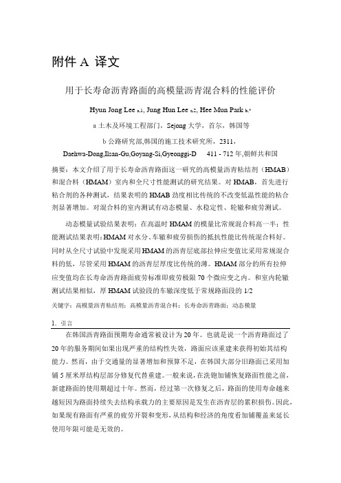
附件A 译文用于长寿命沥青路面的高模量沥青混合料的性能评价Hyun Jong Lee a,1, Jung Hun Lee a,2, HeeMunPark b,*a土木及环境工程部门,Sejong大学,首尔,韩国等b公路研究部,韩国的施工技术研究所,2311,Daehwa-Dong,Ilsan-Gu,Goyang-Si,Gyeonggi-D411 - 712年,朝鲜共和国摘要:本文介绍了用于长寿命沥青路面这一研究的高模量沥青粘结剂(HMAB)和混合料(HMAM)室内和全尺寸性能测试的研究结果。
对HMAB,首先进行粘合剂的各种测试,结果表明的HMAB劲度相比传统的不改变低温性能的粘合剂显著增加。
对混合料的室内测试有动态模量、水稳定性、轮辙和疲劳测试。
动态模量试验结果表明:在高温时HMAM的模量比常规混合料高一半;性能测试结果表明:HMAM对水分、车辙和疲劳损伤的抵抗性能比传统混合料好。
同时从全尺寸试验中发现采用HMAM的沥青层底部拉伸应变值比采用常规混合料的低,尽管采用HMAM的沥青层厚度比传统的薄。
HMAM部分的所有拉伸应变值均在长寿命沥青路面疲劳标准即疲劳极限70个微应变之内。
和室内轮辙测试结果相似,厚HMAM试验段的车辙深度低于常规路面段的1/2关键字:高模量沥青粘结剂;高模量沥青混合料;长寿命沥青路面;动态模量1.引言在韩国沥青路面预期寿命通常被设计为20年。
也就是说一个沥青路面过了20年的服务期间如果出现严重的结构性失效,路面应该重建来获得初始其结构能力。
然而,由于交通量的显著增加和预算不足,在韩国大部分旧路面已采用加铺5厘米厚结构层部分修复代替重建。
一般来说,在洗铇加铺恢复路面性能之前,新建路面的使用期超过十年。
然而,经过第一次修复之后,路面的使用寿命越来越短因为路面持续失去结构承载力的主要原因是发生在沥青层的累积损伤。
因此,如果现有路面有严重的疲劳开裂和变形,从结构和经济的角度看加铺覆盖来延长使用年限可能是无效的。
道路交通工程专业外文翻译外文文献英文文献

土木工程学院交通工程专业中英文翻译Road Design专业:交通工程英文原文The Basics of a Good RoadWe have known how to build good roads for a long time. Archaeologists have found ancient Egyptian roadsthat carried blocks to the pyramids in 4600 BCE. Later,the Romans built an extensive road system, using the same principles we use today. Some of these roads arestill in service.If you follow the basic concepts of road building, you will create a road that will last. The ten commandments of a good road are:(1)Get water away from the road(2)Build on a firm foundation(3)Use the best materials(4)Compact all layers properly(5)Design for traffic loads and volumes(6)Design for maintenance(7)Pave only when ready(8)Build from the bottom up(9)Protect your investment(10)Keep good records1.Get water away from the roadWe can’t overemphasize the importance of good drainage.Engineers estimate that at least 90% of a road’s problems can be related to excess water or to poor waterdrainage. Too much water in any laye r of a road’sstructure can weaken that layer, leading to failure.In the surface layer, water can cause cracks and potholes. In lower layers it undermines support, causing cracks and potholes. A common sign of water in an asphalt road surface is alligator cracking — an interconnected pattern of cracks forming small irregular shaped pieces that look like alligator skin. Edge cracking, frost heaves, and spring breakup of pavements also point to moisture problems.To prevent these problems remember that water:• flows downhill• needs to flow someplace• is a problem if it is not flowingEffective drainage systems divert, drain and dispose of water. To do this they use interceptor ditches and slopes,road crowns, and ditch and culvert systems.Divert —Interceptor ditches, located between the road and higher ground along the road, keep the water from reaching the roadway. These ditches must slope so they carry water away from the road.Drain —Creating a crown in the road so it is higher along the centerline than at the edges encourages water to flow off the road. Typically a paved crown should be 1⁄4" higher than the shoulder for each foot of width from the centerline to the edge. For gravel surfaces the crownshould be 1⁄2" higher per foot of width. For this flow path to work, the road surface must be relatively water tight. Road shoulders also must be sloped away from the road to continue carrying the flow away. Superelevations (banking) at the outside of curves will also help drainthe road surface.Dispose —A ditch and culvert system carries water away from the road structure. Ditches should be at least one foot lower than the bottom of the gravel road layer that drains the roadway. They must be kept clean and must be sloped to move water into natural drainage. If water stays in the ditches it can seep back into the road structure and undermine its strength. Ditches should also be protected from erosion by planting grass, or installing rock and other erosion control measures. Erosion can damage shoulders and ditches, clog culverts, undermine roadbeds, and contaminate nearby streams and lakes. Evaluate your ditch and culvert system twice a year to ensure that it works. In the fall, clean out leaves and branches that can block flow. In spring, check for and remove silts from plowing and any dead plant material left from the fall.2.Build on a firm foundationA road is only as good as its foundation. A highway wears out from the top down but falls apart from the bottom. The road base must carry the entire structure and the traffic that uses it.To make a firm foundation you may need to stabilize the roadbed with chemical stabilizers, large stone called breaker run, or geotextile fabric. When you run into conditions where you suspect that the native soil is unstable, work with an engineer to investigate the situation and design an appropriate solution.3.Use the best materialsWith all road materials you “pay now or pay later.” Inferior materials may require extensive maintenance throughout the road’s life. They may also force you to replace the road prematurely.Crushed aggregate is the best material for the base course. The sharp angles of thecrushed material interlock when they are compacted. This supports the pavement and traffic by transmitting the load from particle to particle. By contrast, rounded particles act like ballbearings, moving under loads.Angular particles are more stable than rounded particles.Asphalt and concrete pavement materials must be of the highest quality, designed forthe conditions, obtained from established firms, and tested to ensure it meets specifications.4.Compact all layersIn general, the more densely a material is compacted, the stronger it is. Compaction also shrinks or eliminates open spaces (voids) between particles. This means that less water can enter the structure. Water in soil can weaken the structure or lead to frost heaves. This is especially important for unsurfaced (gravel) roads. Use gravel which has a mix of sizes (well-graded aggregate) so smaller particles can fill the voids between larger ones. Goodcompaction of asphalt pavement lengthens its life.5.Design for traffic loads and volumesDesign for the highest anticipated load the road will carry. A road that has been designed only for cars will not stand up to trucks. One truck with 9 tons on a single rear axle does as much damage to a road as nearly 10,000 cars.Rural roads may carry log trucks, milk trucks, fire department pumper trucks, or construction equipment. If you don’t know what specific loads the road w ill carry, a good rule of thumb is to design for the largest piece of highway maintenance equipment that will be used on the road.A well-constructed and maintained asphalt road should last 20 years without major repairs or reconstruction. In designing a road, use traffic counts that project numbers and sizes of vehicles 20 years into the future. These are only projections, at best, but they will allow you to plan for traffic loadings through a road’s life.6.Design for maintenanceWithout maintenance a road will rapidly deteriorate and fail. Design your roads so they can be easily maintained. This means:• adequate ditches that can be cleaned regularly• culverts that are marked for easy locating in the spring• enough space for snow after it is plowed off the road• proper cross slopes for safety, maintenance and to avoid snow drifts• roadsi des that are planted or treated to prevent erosion• roadsides that can be mowed safelyA rule of thumb for adequate road width is to make it wide enough for a snowplow to pass another vehicle without leaving the travelled way.Mark culverts with a post so they can be located easily.7.Pave only when readyIt is not necessary to pave all your roads immediately. There is nothing wrong with a well-built and wellmaintained gravel road if traffic loads and volume do not require a paved surface. Three hundred vehicles per day is the recommended minimum to justify paving.Don’t assume that laying down asphalt will fix a gravel road that is failing. Before youpave, make sure you have an adequate crushed stone base that drains well and is properly compacted. The recommended minimum depth of crushed stone base is 10" depending on subgrade soils. A road paved only when it is ready will far outperform one that is constructed too quickly.8.Ê Build from the bottom upThis commandment may seem obvious, but it means that you shouldn’t top dress or resurface a road if the problem is in an underlying layer. Before you do any road improvement, locate the cause of any surface problems. Choose an improvement technique that will address the problem. This may mean recycling or removing all road materials down to the native soil and rebuilding everything. Doing any work that doesn’t solve the problem is a waste of money and effort.9.Ê Protec t your investmentThe road system can be your municipality’s biggest investment. Just as a home needs painting or a new roof, a road must be maintained. Wisconsin’s severe climate requires more road maintenance than in milder places. Do these important maintenance activities: Surface —grade, shape, patch, seal cracks, control dust, remove snow and iceDrainage —clean and repair ditches and culverts; remove all excess materialRoadside —cut brush, trim trees and roadside plantings, control erosionTraffic service —clean and repair or replace signsDesign roads with adequate ditches so they can be maintained with a motor grader. Clean and grade ditches to maintain proper pitch and peak efficiency. After grading, remove all excess material from the shoulder.10.Keep good recordsYour maintenance will be more efficient with good records. Knowing the road’s construction, life, and repair history makes it much easier to plan and budget its future repairs. Records can also help you evaluate the effectiveness of the repair methods and materials you used.Good record keeping starts with an inventory of the system. It should include the history and surface condition of the roadway, identify and evaluate culverts and bridges, note ditch conditions, shoulders, signs, and such structures as retaining walls and guardrails.Update your inventory each year or when you repair or change a road section. A formal pavement management system can help use these records and plan and budget road improvements.ResourcesThe Basics of a Good Road#17649, UW-Madison, 15 min. videotape. Presentsthe Ten Commandments of a Good Road. Videotapes are loaned free through County Extension offices.Asphalt PASER Manual(39 pp), Concrete PASER Manual (48 pp), Gravel PASERManual (32 pp). These booklets contain extensive photos and descriptions of road surfaces to help you understand types of distress conditions and their causes. A simple procedure for rating the condition helps you manage your pavements and plan repairs.Roadware, a computer program which stores and reports pavement conditioninformation. Developed by the Transportation Information Center and enhanced by the Wisconsin Department of Transportation, it uses the PASER rating system to providefive-year cost budgets and roadway repair/reconstruction priority lists.Wisconsin Transportation Bulletin factsheets, available from the Transportation Information Center (T.I.C.).Road Drainage, No. 4. Describes drainage for roadways, shoulders, ditches, and culverts.Gravel Roads, No. 5. Discusses the characteristics of a gravel road and how to maintain one.Using Salt and Sand for Winter Road Maintenance,No. 6. Basic information and practical tips on how to use de-icing chemicals and sand.Culverts—Proper Use and Installation, No. 15. Selecting and sizing culverts, designing, installing and maintaining them.Geotextiles in Road Construction/Maintenance andErosion Control, No. 16. Definitions and common applications of geotextiles onroadways and for erosion control.T.I.C. workshops are offered at locations around the state.Crossroads,an 8-page quarterly newsletter published by the T.I.C. carries helpfularticles, workshop information, and resource lists. For more information on any of these materials, contact the T.I.C. at 800/442-4615.中文译文一个良好的公路的基础长久以来我们已经掌握了如何铺设好一条道路的方法,考古学家发现在4600年古埃及使用建造金字塔的石块铺设道路,后来,罗马人使用同样的方法建立了一个庞大的道路系统,这种方法一直沿用到今天。
公路路面毕业论文中英文资料外文翻译文献
公路路面中英文资料外文翻译文献PavementHighway pavements are divided into two main categories: rigitand flexible.The wearing surfaceof a rigid pavement is usually constructed of Portland cement concrete such that it acts like a beam over any irregularities in the underlying supporting material.The wearing surface of flexible pavements, on the other hand, is usually constructed of bituminous material such that they remain in contact with the underlying material even when minor irregularities occur.Flexible pavements usually consist of a bituminous surface underlaid with a layer of granular material and a layer of a suitable mixture of coarse and fine materials.Coarse aggregatesFine aggregatesTraffic loads are transferred by the wearing surface to the underlying supporting materials through the interlocking of aggregates, the frictionaleffect of the granular materials, and the cohesion of the fine materials.Flexible pavements are further divided into three subgroups: high type, intermediate type, and low type. High-type pavements have wearing surfaces that adequately support the expected traffic load without visible distress due to fatigue and are not susceptible to weather conditions.Intermediate-type pavements have wearing surfaces that range from surface treated to those with qualities just below that of high-type pavements. Low-type pavements are used mainly for low-cost roads and have wearing surfaces that range from untreated to loose natural materials to surface-treated earth.The components of a flexible pavement include the subgradeor preparedroadbed, the subbase, basecourse, and the surface course (Fig.11.1).✹Upper surface courseMiddle surface courseLower surface courseThe performance of the pavement depends on the satisfactory performance of each component, which requires proper evaluation of the properties of each component separately.✹The subgrade is usually the natural material located along the horizontal alignment of the pavement and serves as the foundation of the pavement structure.✹The subgrademay also consist of a layer of selected borrow materials, well compacted to prescribedspecifications.✹Compacting plantCompaction deviceCompactnessIt may be necessary to treat the subgrade material to achieve certain strength properties required for the type of pavement being constructed.Located immediately above the subgrade, the subbase component consists of a superior quality to that which generally is used for subgrade construction. The requirements for subbase materials are usually given in terms of the gradation, plastic characteristics, and strength. When the quality of the subgrade material meets the requirements of the subbase material, the subbase component may be omitted.In cases where suitable subbase material is not readily available ,the available material can be treated with other materials to achieve the necessary properties. This process of treating soils to improve their engineering properties is know as stabilization.✹The base course lies immediately above the subbase. It is placed immediately above the subgrade if a subbase course is not used.✹This course usually consists of granular materials such as crushed stone, crushed or uncrushed.The specifications for base course materials usually include stricter requirements than those for subbase materials, particularly with respect to their plasticity, gradation, and strength.Materials that do not have the required properties can be used as base materials if they are properly stabilized with Portland cement, asphalt, or lime .In some cases, high-quality base course materials may also be treated with asphalt or Portland cement to improve the stiffness characteristics of heavy-duty pavementsThe surface course is the upper course of the road pavement and is constructed immediately above the base course. The surface course in flexible pavement usually consists of a mixture of mineral aggregates and asphaltic materials.It should be capable of withstanding high tire pressures, resisting the abrasive forces due to traffic, providing a skid-resistant driving surface, and preventing thepenetration of surface water into the underlying layers.✹The thickness of the wearing surface can vary from 3 in. to more than 6 in.(inch,英寸,2.54cm), depending on the expected traffic on the pavement.It was shown that the quality of the surface course of a flexible pavement depends on the mix design of the asphalt concrete used.✹Rigid highway pavements usually are constructed to carry heavy traffic loads, although they have been used for residential and local roads. Properly designed and constructed rigid pavements have long service lives and usually are less expensive to maintain than the flexible pavements.✹The Portland cement concrete commonly used for rigid pavements consists of Portland cement, coarse aggregate, fine aggregate, and water. Steel reinforcing rods may or may not be used, depending on the type of pavement being constructed.Rigid highway pavements be divided into three general type: plain concrete pavements, simply reinforced concrete pavements, and continuously reinforced concrete pavement. The definition of each pavement type is related to the amount of reinforcement used.Plain concrete pavement has no temperature steel or dowels for load transfer. However, steel tie bars are often used to provide a hingeeffect at longitudinal joints and to prevent the opening of these joints. Plain concrete pavements are used mainly on low-volume highways or when cement-stabilized soils are used as subbase.✹Joints are placed at relatively shorter distances (10 to 20 ft) than with the other types of concrete pavements to reduce the amount of cracking.In some case, the transverse joints of plain concrete pavements are skewed about 4 to 5 ft in plan, such that only one wheel of a vehicle passes through the joint at a time. This helps to provide a smoother ride.Simply reinforced concrete pavements have dowels for the transfer of traffic loads across joints, with these joints spaced at larger distances, ranging from 30 to 100 ft. Temperature steel is used throughout the slab, with the amount dependent on the length of the slab. Tie bars are also commonly used in longitudinal joints.h/2 h/25~10cm 填缝料横向施工缝构造Continuously reinforced concrete pavements have no transverse joints, except construction joints or expansion joints when they are necessary at specific positions, such as at bridges.These pavements have a relatively high percentage of steel, with the minimum usually at 0.6 percent of the cross section of the slab. They also contain tie bars across the longitudinal joints.Bituminous Surface CoursesThe bituminous surface course has to provide resistance to the effects of repeated loading by tyres and to the effects of the environment.✹ In addition, it must offer adequate skid resistance in wet weather as well ascomfortable vehicle ride. It must also be resistant to rutting and to cracking.✹ It is also desirable that surface course is impermeable, except in the case ofporous asphalt.Hot rolled asphalt (HRA) is a gapgraded material with less coarse aggregate. In fact it is essentially a bitumen/fine aggregate/filler mortar into which some coarse aggregate is placed.The mechanical propertiesare dominated by those of the mortar. This material has been extensively used as the wearing course on major road in the UK, though its use has recently declined as new materials have been introduced.✹ It provides a durablelayer with good resistance to cracking and one which isrelatively easy to compact. The coarse aggregate content is low (typically 30%) which results in the compacted mixture having a smooth surface. Accordingly, the skid resistance is inadequate and precoated chippings are rolled into the surface at the time of laying to correct this deficiency.In Scotland, HRA wearing course remains the preferred wearing course on trunk roads including motorway but , since 1999 thin surfacings have been the preferred option in England and Wales. Since 1999 in Northern Ireland, HRA wearing course and thin surfacings are the preferred permitted options.Porous asphalt (PA) is a uniformly graded material which is designed to provide平缝加拉杆型large air voids so that water can drain to the verges within the layer thickness. If the wearing course is to be effective, the basecourse below must be waterproof and the PA must have the ability to retain its open textured properties with time.Thick binder films are required to resist water damage and ageing of the binder. In use, this material minimizes vehicle spray, provides a quiet ride and lower rolling resistance to traffic than dense mixtures.✹It is often specified for environmental reasons but stone mastic asphalt (SMA) and special thin surfacings are generally favoured in current UK practice.There have been high profile instances where a PA wearing course has failed early in its life. The Highways Agency does not recommend the use of a PA at traffic levels above 6000 commercial vehicles per day.✹Asphaltic concrete and dense bitumen macadam (DBM) are continuously graded mixtures similar in principle to the DBMs used in roadbases and basecourses but with smaller maximum particle sizes. Asphaltic concrete tends to have a slightlydenser grading and is used for road surfaces throughout the world with the excepting of the UK.✹It is more difficult to meet UK skid resistance Standards with DBMs than HRA, SMA or PA. This problem can be resolves by providing a separate surface treatment but doing so generally makes DBM economically unattractive.✹Stone mastic asphalt (SMA) material was pioneeredin Germany and Scandinavia and is now widely used in the UK. SMA has a coarse, aggregrate skeleton, like PA, but the voids are filled with a fine aggregate/filler /bitumen mortar.✹In mixtures using penetration grade bitumen , fibres are added to hold the bitumen within the mixture (to prevent “binder drainage”).Bitumen✹oil bitumen( earth oil)✹natural bitumen✹TarWhere a polymer modified bitumen is used, there is generally no need for fibres. SMA is a gap-graded material with good resistance to rutting and high durability. modified bitumen✹SBS✹SBR✹PE\EV A✹It differs from HRA in that the mortar is designed to just fill the voids in the coarse aggregate whereas, in HRA, coarse aggregate is introduced into the mortar and does not provide a continous stone matrix. The higher stone content HRAs ,however, are rather similar to SMA but are not wide used as wearing courses in the UK, being preferred for roadbase and basecourse construction.A variety of thin and what were called ultra thin surfacings (nowadays, the tendency is to use the term ‘thin surfacings’ for both thin and ultra thin surfacings )have been introduced in recent years, principally as a result of development work concentrated in France.These materials vary in their detailed constituents but usually have an aggregate grading similar to SMA and often incorporate a polymer modified bitumen.They may be used over a high stiffness roadbase and basecourse or used for resurfacing of existing pavements. For heavy duty pavements (i .e those designed to have a useful life of forty years), the maintenance philosophy is one of minimum lane occupancy, which only allows time for replacement of the wearing course to these ‘long life’ pavement structures. The new generation of thin s urfacings allows this to be conveniently achieved.The various generic mixture types described above can be compared with respect to their mechanical properties and durability characteristics by reference to Fig.12.1. This shows, in principle, how low stone content HRA, asphaltic concrete, SMA and PA mixtures mobilize resistance to loading by traffic.Asphaltic concrete (Fig.12.1a)) presents something of a compromise when well designed, since the dense aggregate grading can offer good resistance to the shear stresses which cause rutting, while an adequate binder content will provide reasonable resistance to the tensile stresses which cause cracking.In general, the role of the aggregate dominates. DBMs tend to have less dense gradings and properties which, therefore, tend towards good rutting resistance and away from good crack resistance.HRA (Fig.12.1b)) offers particularly good resistance to cracking through the binder rich mortar between the coarse aggregate particles. This also provides good durability but the lack of coarse aggregate content inhibits resistance to rutting.SMA and PA are shown in the same diagram ( Fig.c)) to emphasis the dominant role the coarse aggregate. In both case, well coated stone is used. In PA, the void space remains available for drainage of water, whilst in SMA, the space is occupied by a fine aggregate/ filler/ bitumen/ fibre mortar.Both materials offer good rutting resistance through the coarse aggregate content. The tensile strength of PA is low whilst that of SMA is probably adequate but little mechanical testing data have been reported to date.Drainage for Road and Airports✹Provision of adequate drainage is important factor in the location and geometric design of road and airports. Drainage facilities on any highway, street and airport should adequately provide for the flow of water away from the surface of the pavement to properly designed channels.Inadequate drainage will eventually result in serious damage to the structure.✹In addition, traffic may be slowed by accumulated water on the pavement, and accidents may occur as a result of hydroplaning and loss of visibility from splash and spray. The importance of adequate drainage is recognized in the amount of highway construction dollars allocated to drainage facilities. About25 percent of highway construction dollars are spent for erosion control anddrainage structures, such as culverts, bridges, channels, and ditches.✹Highway Drainage Structures✹One of the main concerns of the highway engineer is to provide an adequate size structure, such that the waterway opening is sufficiently large to discharge the expected flow of water.Inadequately sized structures can result in water impounding, which may lead to failure of the adjacent sections of the highway due to embankments being submerged in water for long periods.✹The two general categories of drainage structures are major and minor. Major structures are those with clear spans greater than 20 feet, whereas minor structures are those with clear spans of 20 feet or less .✹Major structures are usually large bridges, although multiple-span culverts may also be included in this class. Minor structures include small bridges and culverts.Emphasis is placed on selecting the span and vertical clearancerequirements for major structures. The bridge deck should be located above the high water mark .The clearance above the high water mark depends on whether the waterway is navigable ✹If the waterway is navigable, the clearance above the high water mark should allow the largest ship using the channel to pass underneath the bridge without colliding with the bridge deck. The clearance height, type, and spacing of piers also depend on the probability of ice jams and the extentto which floating logs and debris appear on the waterway during high water.✹An examination of the banks on either side of the waterway will indicate the location of the high water mark, since this is usually associated with signs of erosion and debris deposits. Local residents, who have lived near and observed the waterway during flood stages over a number of years, can also give reliable information on the location of the high water mark. Stream gauges that have been installed in the waterway for many years can also provide data that can be used to locate the high water mark.Minor structures, consisting of short-span bridges and culverts, are the predominant type of drainage structures on highways. Although openings for these structures are not designed to be adequate for the worst flood conditions, they should be large enough to accommodate the flow conditions that might occur during the normal life expectancy of the structure.✹Provision should also be made for preventing clogging of the structure due to floating debris and large boulders rolling from the banks of steep channels.✹Culverts are made of different materials and in different shapes. Materials used to construct culverts include concrete(reinforced and unreinforced), corrugated steel, and corrugatedaluminum. Other materials may also be used to line the interiorof the culvert to prevent corrosion and abrasionor to reduce hydraulic resistance. For example, asphaltic concrete may be used to line corrugated metal culverts. The different shapes normally used in culvert construction include circular, rectangular (box), elliptical, pipe arch, metal box, and arch.✹The drainage problem is increased in these areas primarily for two reasons: the impervious nature of the area creates a very high runoff; and there is little room for natural water courses. It is often necessary to collect the entire storm water into a system of pipes and transmit it over considerable distances before it can be loosed again as surface runoff. This collection and transmission further increase the problem, since all of the water must be collected with virtually no pending, thus eliminating any natural storage; and through increased velocity the peak runoffs are reached more quickly.Also, the shorter times of peaks cause the system to be more sensitive to short-duration,high intensive rainfall.Storm sewers,like culverts and bridges,are designed for storms of various intensity-return-period relationships, depending uponthe economy and amount of ponding that can be tolerated.✹Airport Drainage✹The problem of providing proper drainage facilities for airports is similar in many ways to that of highways and streets. However, because of the large and relatively flat surface involved, the varying soil conditions, the absence of natural water courses and possible side ditches, and the greater concentration of discharge at the terminus of the construction area, some phases of the problem are more complex. For the average airport the over-all area to be drained is relatively large and an extensive drainage system is required. The magnitude of such a system makes it even more imperative that sound engineering principles based on all of the best available data be used to ensure the most economical design.Overdesigning of facilities results in excessive money investment with no return, and underdesigning can result in conditions hazardous to the air traffic using the airport. In order to ensure surfaces that are smooth, firm, stable, and reasonably free from flooding, it is necessary to provide a system which will do several things.It must collect and remove the surface water from the airport surfaces; intercept and remove surface water flowing toward the airport from adjacent areas; collect and remove any excessive subsurface water beneath the surface of the airport facilities and in many cases lower the ground-water table; and provide protection against erosion of the sloping areas.路面公路的路面被分为两类:刚性的和柔性的。
沥青路面的养护发展外文文献翻译、中英文翻译、外文翻译

沥青路面的养护发展外文文献翻译、中英文翻译、外文翻译XXX and climate impacts。
leading to physical and chemical XXX over time。
This can result in us types of damage such as pits。
cracks。
swarming spores。
subsidence。
XXX eating。
peeling。
and loosening。
If left unrepaired。
these damages XXX vehicles。
XXX damage。
To address this issue。
XXX.2 n and nXXX us types of equipment and tools。
such as asphalt mixers。
road cutting machines。
and hydraulic systems。
to XXX efficient manner。
XXX.3 Development of XXXXXX has been driven by the need to XXX。
Over the years。
us types of XXXXXX.4 nIn n。
XXX damage over time。
which can affect the normal passage of vehicles and lead to even greater damage if left unrepaired。
To address this issue。
XXX。
The development of these vehicles has XXX.This article discusses the two categories of road maintenance XXX: XXX.XXX Maintenance vehicles XXX: trailers and self-XXX as the self-end。
毕设必备道路桥梁专业毕业设计英文翻译(英文原文+中文翻译)

Accident Analysis and PreventionThis paper describes a project undertaken to establish a self-explaining roads (SER) design programmeon existing streets in an urban area. The methodology focussed on developing a process to identifyfunctional road categories and designs based on endemic road characteristics taken from functionalexemplars in the study area. The study area was divided into two sections, one to receive SER treatments designed to maximise visual differences between road categories, and a matched control area to remainuntreated for purposes of comparison. The SER design for local roads included increased landscaping andcommunity islands to limit forward visibility, and removal of road markings to create a visually distinctroad environment. In comparison, roads categorised as collectors received increased delineation, additionof cycle lanes, and improved amenity for pedestrians. Speed data collected 3 months after implementationshowed a significant reduction in vehicle speeds on local roads and increased homogeneity of speeds onboth local and collector roads. The objective speed data, combined with r esidents’ speed choice ratings,indicated that the project was successful in creating two discriminably different road categories.2010 Elsevier Ltd. All rights reserved.1. Introduction1.1. BackgroundChanging the visual characteristics of roads to influencedriver behaviour has come to be called the self-explaining roads(SER) approach (Theeuwes, 1998; Theeuwes and Godthelp, 1995;Rothengatter, 1999). Sometimes referred to as sustainable safety,as applied in the Netherlands, the logic behind the approach isthe use of road designs that evoke correct expectations and drivingbehaviours from road users (Wegman et al., 2005; Weller etal., 2008). The SER approach focuses on the three key principlesof functionality, homogeneity, and predictability (van Vliet andSchermers, 2000). In practice, functionality requires the creation ofa few well-defined road categories (e.g., through roads, distributorroads, and access roads) and ensuring that the use of a particularroad matches its intended function. Multifunctional roadslead to contradictory design requirements, confusion in the mindsof drivers, and incorrect expectations and inappropriate drivingbehaviour. Clearly defined road categories promote homogeneity intheir use and prevent large differences in vehicle speed, direction,and mass. Finally, predictability, or recognisability, means keepingthe road design and layout within each category as uniform as possibleand clearly differentiated from other categories so that thefunction of a road is easily recognised and will elicit the correctbehaviour from road users. The SER approach has been pursued tothe largest extent in the Netherlands and the United Kingdom but ithas also been of some interest inNewZealand. In 2004, the NationalRoad Safety Committee and the Ministry of Transport articulateda new National Speed Management Initiative which stated “Theemphas is is not just on speed limit enforcement, it includes perceptualmeasures that influence the speed that a driver feels is appropriatefor the section of road upon which they are driving–in effect the ‘selfexplainingroad”’ (New Zealand Ministry of Transport, 2004).In cognitive psychological terms, the SER approach attempts toimprove road safety via two complementary avenues. The first is toidentify and use road designs that afford desirable driver behaviour.Perceptual properties such as road markings, delineated lane width,and roadside objects can function as affordances that serve as builtininstructions and guide driver behaviour, either implicitly orexplicitly (Charlton, 2007a; Elliott et al., 2003; Weller et al., 2008).This work is more or less a direct development of work on perceptualcountermeasures, perceptual cues in the roading environmentthat imply or suggest a particular speed or lane position, eitherattentionally or perceptually (Charlton, 2004, 2007b; Godley et al.,1999).A second aspect of the SER approach is to establish mentalschemata and scripts, memory representations that will allowroad users to easily categorise the type of road on which they are.1.2. Localised speed managementThe traditional approaches to improving speed management,traffic calming and local area traffic management (LATM) havefocussed on treating specific problem locations or “black spots”in response to crash occurrences or complaints from the public(Ewing, 1999). A potential disadvantage of these approaches is thataddressing the problem with localised treatments can lead to are-emergence of the problem at another location nearby. Further,when applied inappropriately, localised approaches may addressthe problem from only one perspective, without considering theimpact on other types of road users or residents. When traffic calmingtreatments rely on physical obstacles such as speed humpsthey can be very unpopular with bothresidents and road users andcan create new problems associated with noise, maintenance, andvandalism (Martens et al., 1997).From an SER perspective, treatments that are highly localizedor idiosyncratic may do more harm than good by adding to themultiplicity of road categories and driver uncertainty, rather thanbuilding driver expectations around a few uniform road types.Instead of considering a single location in isolation, SER roaddesigns are considered within a hierarchy of road functions; e.g.,access roads, collector roads, and arterial roads. Although SERschemes may employ physical design elements used in trafficcalming schemes (e.g., road narrowing with chicanes and accesscontrols) they also employ a range of more visually oriented featuressuch as median and edge line treatments, road markings,pavement surfaces, and roadside furniture. For an effective SERscheme it is important to select the combination of features that will afford the desired driver speeds and to ensure their consistentuse to form distinct categories of road types (van der Horst andKaptein, 1998; Wegman et al., 2005).road category that would meet the three SER principles of functional use, homogeneous use, and predictable use. Herrstedt (2006)reported on the use of a standardised catalogue of treatments compiledfrom researcher and practitioner advice. Goldenbeld and vanSchagen (2007) used a survey technique to determine road characteristicsthat minimise the difference between drivers’ ratingsof preferred speed and perceived safe speed and select road featuresthat make posted speeds “credible”. Aarts and Davidse (2007)used a driving simulator to verify whether the “essential recognisabilitycharacteristics” of different road classes conformed to theexpectations of road users. Weller et al. (2008) employed a range of statistical techniques, including factor analysis and categoricalclustering to establish the road characteristics that drivers use tocategorise different road types.The practical difficulties of implementing an SER system thusbecome a matter of finding answers to a series of questions. Howdoes one create a discriminable road hierarchy for an existingroad network? What road characteristics should be manipulatedto establish category-defining road features? How can SER roadfeatures and selection methods be made relevant and appropriatefor a local context? (Roaddesigns appropriate for The Netherlandswould not be suitable in New Zealand, in spite of its name.) A surveyof national and international expert opinion in order establishcategory-defining road features for New Zealand roads revealedthat the regional character and local topography of roads oftenundercut the usefulness of any standardised catalogue of designcharacteristics (Charlton and Baas, 2006).1.4. Goals of the present projectThe project described in this paper sought to develop anddemonstrate an SER process based on retrofitting existing roadsto establish a clear multi-level road hierarchy with appropriatedesign speeds, ensuring that each level in the hierarchy possesseda different “look and feel”. Rather than transferring SER designs already in use internationally, the project attempted to develop amethod that would build on the features of roads in the local area;extending road characteristics with desirable affordances to otherroads lacking them and creating discriminable road categories inthe process. Of interest was whether such a process could producecost-effective designs and whether those designs would be effectivein creating different road user expectations and distinct speedprofiles for roads of different categories.2. MethodsThe research methodology/SER design process developed forthis project progressed through a series of five stages: (1) selectionof study area; (2) identification of the road hierarchy; (3) analysisof the road features; (4) development of a design template; and (5)implementation and evaluation of the SER treatments. Each of thestages is described in the sections that follow.2.1. Selection of study areaThe study area for this project (Pt England/Glen Innes in Auckland)was selected in consultation with a project steering groupcomprised of representatives from the Ministry of Transport, NewZealand Transport Agency, New Zealand Police, and other localtransport and urban agencies. The study area was an establishedneighbourhood contained amix of private residences, small shops,schools, and churches, and was selected, in part, because of its historyof cyclist, pedestrian and loss of controlcrashes, almost twicethe number。
沥青混凝土中英文对照外文翻译文献
(文档含英文原文和中文翻译)中英文对照翻译Asphalt Mixtures-Applications, Theory andPrinciples1 . ApplicationsAsphalt materials find wide usage in the construction industry. The use of asphalt as a cementing agent in pavements is the most common of its applications, however, and the one that will be considered here.Asphalt products are used to produce flexible pavements for highways and airports. The term “flexible” is used to distinguish these pavements from those made with Portland cement, which are classified as rigid pavements, that is, having beam strength. This distinction is important because it provides they key to the design approach which must be used for successful flexible pavement structures.The flexible pavement classification may be further broken down into high and low types, the type usually depending on whether a solid or liquid asphalt product is used. The low types of pavement are made with the cutback, or emulsion, liquid products and are very widely used throughout this country. Descriptive terminologyhas been developed in various sections of the country to the extent that one pavement type may have several names. However, the general process followed in construction is similar for most low-type pavements and can be described as one in which the aggregate and the asphalt product are usually applied to the roadbed separately and there mixed or allowed to mix, forming the pavement.The high type of asphalt pavements is made with asphalt cements of some selected penetration grade.Fig. ·1 A modern asphalt concrete highway. Shoulder striping is used as a safely feature.Fig. ·2 Asphalt concrete at the San Francisco International Airport.They are used when high wheel loads and high volumes of traffic occur and are, therefore, often designed for a particular installation.2 . Theory of asphalt concrete mix designHigh types of flexible pavement are constructed by combining an asphalt cement, often in the penetration grade of 85 to 100, with aggregates that are usually divided into three groups, based on size. The three groups are coarse aggregates, fine aggregates, and mineral filler. These will be discussed in detail in later chapter.Each of the constituent parts mentioned has a particular function in the asphalt mixture, and mix proportioning or design is the process of ensuring that no function is neglected. Before these individual functions are examined, however, the criteria for pavement success and failure should be considered so that design objectives can be established.A successful flexible pavement must have several particular properties. First, it must be stable, that is to resistant to permanent displacement under load. Deformation of an asphalt pavement can occur in three ways, two unsatisfactory and one desirable.Plastic deformation of a pavement failure and which is to be avoided if possible. Compressive deformation of the pavement results in a dimensional change in the pavement, and with this change come a loss of resiliency and usually a degree of roughness. This deformation is less serious than the one just described, but it, too, leads to pavement failure. The desirable type of deformation is an elastic one, which actually is beneficial to flexible pavements and is necessary to their long life.The pavement should be durable and should offer protection to the subgrade. Asphalt cement is not impervious to the effects of weathering, and so the design must minimize weather susceptibility. A durable pavement that does not crack or ravel will probably also protect the roadbed. It must be remembered that flexible pavements transmit loads to the subgrade without significant bridging action, and so a dry firm base is absolutely essential.Rapidly moving vehicles depend on the tire-pavement friction factor for control and safety. The texture of the pavement surfaces must be such that an adequate skid resistance is developed or unsafe conditions result. The design procedure should be used to select the asphalt material and aggregates combination which provides a skid resistant roadway.Design procedures which yield paving mixtures embodying all these properties are not available. Sound pavements are constructed where materials and methods are selected by using time-tested tests and specifications and engineering judgments along with a so-called design method.The final requirement for any pavement is one of economy. Economy, again, cannot be measured directly, since true economy only begins with construction cost and is not fully determinable until the full useful life of the pavement has been recorded. If, however, the requirements for a stable, durable, and safe pavement are met with a reasonable safety factor, then the best interests of economy have probably been served as well.With these requirements in mind, the functions of the constituent parts can be examined with consideration give to how each part contributes to now-established objectives or requirements. The functions of the aggregates is to carry the load imposed on the pavement, and this is accomplished by frictional resistance and interlocking between the individual pieces of aggregates. The carrying capacity of the asphalt pavement is, then, related to the surface texture (particularly that of the fine aggregate) and the density, or “compactness,”, of the aggregates. Surfa ce texturevaries with different aggregates, and while a rough surface texture is desired, this may not be available in some localities. Dense mixtures are obtained by using aggregates that are either naturally or artificially “well graded”. This means tha t the fine aggregate serves to fill the voids in the coarser aggregates. In addition to affecting density and therefore strength characteristics, the grading also influences workability. When an excess of coarse aggregate is used, the mix becomes harsh and hard to work. When an excess of mineral filler is used, the mixes become gummy and difficult to manage.The asphalt cement in the flexible pavement is used to bind the aggregate particles together and to waterproof the pavements. Obtaining the proper asphalt content is extremely important and bears a significant influence on all the items marking a successful pavement. A chief objective of all the design methods which have been developed is to arrive at the best asphalt content for a particular combination of aggregates.3 . Mix design principlesCertain fundamental principles underlie the design procedures that have been developed. Before these procedures can be properly studied or applied, some consideration of these principles is necessary.Asphalt pavements are composed of aggregates, asphalt cement, and voids. Considering the aggregate alone, all the space between particles is void space. The volume of aggregate voids depends on grading and can vary widely. When the asphalt cement is added, a portion of these aggregate voids is filled and a final air-void volume is retained. The retention of this air-void volume is very important to the characteristics of the mixture. The term air-void volume is used, since these voids are weightless and are usually expressed as a percentage of the total volume of the compacted mixture.An asphalt pavement carries the applied load by particle friction and interlock. If the particles are pushed apart for any reason , then the pavement stability is destroyed. This factor indicates that certainly no more asphalt should be added than the aggregate voids can readily hold. However ,asphalt cement is susceptible to volume change and the pavement is subject to further compaction under use. If the pavement has no air voids when placed, or if it loses them under traffic, then the expanding asphalt will overflow in a condition known as bleeding. The loss of asphalt cement through bleeding weakens the pavement and also reduces surface friction, making the roadwayhazardous.Fig. ·3 Cross section of an asphalt concrete pavement showing the aggregate framework bound together by asphalt cement.The need for a minimum air-void volume (usually 2 or 3 per cent ) has been established. In addition, a maximum air-void volume of 5 to 7 per cent should not be exceed. An excess of air voids promotes raveling of the pavement and also permits water to enter and speed up the deteriorating processes. Also, in the presence of excess air the asphalt cement hardens and ages with an accompanying loss of durability and resiliency.The air-void volume of the mix is determined by the degree of compaction as well as by the asphalt content. For a given asphalt content, a lightly compacted mix will have a large voids volume and a lower density and a greater strength will result. In the laboratory, the compaction is controlled by using a specified hammer and regulating the number of blows and the energy per blow. In the field, the compaction and the air voids are more difficult to control and tests must be made no specimens taken from the compacted pavement to cheek on the degree of compaction being obtained. Traffic further compact the pavement, and allowance must be made for this in the design. A systematic checking of the pavement over an extended period is needed to given factual information for a particular mix. A change in density of several per cent is not unusual, however.Asphalt content has been discussed in connection with various facets of the ix design problem. It is a very important factor in the mix design and has a bearing an all the characteristics ld a successful pavement: stability, skid resistance, durability, and economy. As has been mentioned, the various design procedures are intended to provide a means for selecting the asphalt content . These tests will be considered indetail in a future chapter ,but the relationship between asphalt content and the measurable properties of stability, unit weight, and air voids will be discussed here.Fig.4 Variations in stability, unit weight, and air-void content with asphalt cement content.If the gradation and type of aggregate, the degree of compaction, and the type of asphalt cement are controlled, then the strength varies in a predictable manner. The strength will increase up to some optimum asphalt content and then decrease with further additions. The pattern of strength variation will be different when the other mix factors are changed, and so only a typical pattern can be predicted prior to actual testing.Unit weight varies in the same manner as strength when all other variable are controlled. It will reach some peak value at an asphalt content near that determined from the strength curve and then fall off with further additions.As already mentioned, the air-void volume will vary with asphalt content. However, the manner of variation is different in that increased asphalt content will decrease air-void volume to some minimum value which is approached asymptotically. With still greater additions of asphalt material the particles of aggregate are only pushed apart and no change occurs in air-void volume.In summary, certain principles involving aggregate gradation, air-void volume, asphalt content, and compaction mist be understood before proceeding to actual mix design. The proper design based on these principles will result in sound pavements. If these principles are overlooked, the pavement may fail by one or more of the recognized modes of failure: shoving, rutting, corrugating, becoming slick when the max is too …rich‟; raveling, cracking,having low durability when the mix is too …lean‟.It should be again emphasized that the strength of flexible is, more accurately, astability and does not indicate any ability to bridge weak points in the subgrade by beam strength. No asphalt mixture can be successful unless it rests on top of a properly designed and constructed base structure. This fact, that the surface is no better than the base, must be continually in the minds of those concerned with any aspect of flexible pavement work.译文:沥青混合料的应用、理论和原则1、应用沥青材料如今在建筑行业广泛使用。
道路工程(路桥)毕业设计外文文献翻译

外文文献翻译原文:Asphalt Mixtures-Applications, Theory and Principles1 . ApplicationsAsphalt materials find wide usage in the construction industry. The use of asphalt as a cementing agent in pavements is the most common of its applications, however, and the one that will be consid ered here.Asphalt products are used to produce flexibl e pavements for highways and airports. The term “fl exible” is used to distinguish these pavements from those made with Portland cement, which are classified as rigid pavements, that is, having beam strength. This distinction is important because it provid es they key to the design approach which must be used for successful flexibl e pavement structures.The flexibl e pavement classification may be further broken d own into high and l ow types, the type usually depending on whether a solid or liquid asphalt product is used. The l ow types of pavement are mad e with the cutback, or emulsion, liquid products and are very widely used throughout this country. Descriptive terminology has been devel oped in various sections of the country to the extent that one pavement type may have several names. However, the general process foll owed in construction is similar for most l ow-type pavements and can be described as one in which the aggregate and the asphalt product are usually applied to the roadbed separately and there mixed or all owed to mix, forming the pavement.The high type of asphalt pavements is made with asphalt cements of some sel ected penetration grad e.Fig. ·1 A modern asphalt concrete highway. Should er striping is used as a safely feature.Fig. ·2 Asphalt concrete at the San Francisco International Airport.They are used when high wheel l oads and high volumes of traffic occur and are, therefore, often designed for a particular installation.2 . Theory of asphalt concrete mix designHigh types of flexible pavement are constructed by combining an asphalt cement, often in the penetration grad e of 85 to 100, with aggregates that are usually divided into three groups, based on size. The three groups are coarse aggregates, fine aggregates, and mineral filler. These will be discussed in d etail in later chapter.Each of the constituent parts mentioned has a particular function in the asphalt mixture, and mix proportioning or d esign is the process of ensuring that no function is negl ected. Before these individual functions are examined, however, the criteria for pavement success and failure should be consid ered so that d esign objectives can be established.A successful fl exible pavement must have several particular properties. First, it must be stable, that is to resistant to permanent displacement under l oad. Deformation of an asphalt pavement can occur in three ways, two unsatisfactory and one desirable. Plastic d eformationof a pavement failure and which is to be avoid ed if possible. Compressive deformation of the pavement results in a dimensional change in the pavement, and with this change come a l oss of resiliency and usually a d egree of roughness. This deformation is less serious than the one just described, but it, too, leads to pavement failure. The desirabl e type of deformation is an elastic one, which actually is beneficial to flexibl e pavements and is necessary to their long life.The pavement should be durable and should offer protection to the subgrade. Asphalt cement is not impervious to the effects of weathering, and so the design must minimize weather susceptibility. A durable pavement that does not crack or ravel will probably also protect the roadbed. It must be remembered that fl exible pavements transmit l oads to the subgrad e without significant bridging action, and so a dry firm base is absolutely essential.Rapidly moving vehicl es d epend on the tire-pavement friction factor for control and safety. The texture of the pavement surfaces must be such that an adequate skid resistance is developed or unsafe conditions result. The design procedure should be used to sel ect the asphalt material and aggregates combination which provid es a skid resistant roadway.Design procedures which yield paving mixtures embodying all these properties are not available. Sound pavements are constructed where materials and methods are selected by using time-tested tests and specifications and engineering judgments al ong with a so-call ed design method.The final requirement for any pavement is one of economy. Economy, again, cannot be measured directly, since true economy only begins with construction cost and is not fully determinable until the full useful life of the pavement has been record ed. If, however, the requirements for a stable, durable, and safe pavement are met with a reasonable safety factor, then the best interests of economy have probably been served as well.With these requirements in mind, the functions of the constituent parts can be examined with consideration give to how each part contributes to now-established objectives or requirements. The functions of the aggregates is to carry the l oad imposed on the pavement, and this is accomplished by frictional resistance and interl ocking between the individual pieces of aggregates. The carrying capacity of the asphalt pavement is, then, related to the surface texture (particularly that of the fine aggregate) and the density, or “compactness,”, of the aggregates. Surface texture varies with different aggregates, and while a rough surfacetexture is desired, this may not be available in some l ocalities. Dense mixtures are obtained by using aggregates that are either naturally or artificially “well grad ed”. This means that the fine aggregate serves to fill the voids in the coarser aggregates. In addition to affecting density and therefore strength characteristics, the grading also influences workability. When an excess of coarse aggregate is used, the mix becomes harsh and hard to work. When an excess of mineral filler is used, the mixes become gummy and difficult to manage.The asphalt cement in the fl exibl e pavement is used to bind the aggregate particl es together and to waterproof the pavements. Obtaining the proper asphalt content is extremely important and bears a significant influence on all the items marking a successful pavement. A chief objective of all the design methods which have been devel oped is to arrive at the best asphalt content for a particular combination of aggregates.3 . Mix design principl esCertain fundamental principles underlie the design procedures that have been developed. Before these procedures can be properly studied or applied, some consid eration of these principles is necessary.Asphalt pavements are composed of aggregates, asphalt cement, and voids. Consid ering the aggregate alone, all the space between particles is void space. The volume of aggregate voids depends on grading and can vary widely. When the asphalt cement is ad ded, a portion of these aggregate voids is fill ed and a final air-void volume is retained. The retention of thisair-void volume is very important to the characteristics of the mixture. The term air-void volume is used, since these voids are weightless and are usually expressed as a percentage of the total volume of the compacted mixture.An asphalt pavement carries the applied load by particl e friction and interlock. If the particl es are pushed apart for any reason , then the pavement stability is d estroyed. This factor indicates that certainly no more asphalt shoul d be ad ded than the aggregate voids can readily hold. However ,asphalt cement is susceptible to volume change and the pavement is subject to further compaction under use. If the pavement has no air voids when placed, or if it loses them under traffic, then the expanding asphalt will overfl ow in a condition known as bleeding. The l oss of asphalt cement through bl eeding weakens the pavement and also reduces surface friction, making the roadway hazard ous.Fig. ·3 Cross section of an asphalt concrete pavement showing the aggregate framework bound together by asphalt cement.The need for a minimum air-void volume (usually 2 or 3 per cent ) has been established. In addition, a maximum air-void volume of 5 to 7 per cent shoul d not be exceed. An excess of air voids promotes raveling of the pavement and also permits water to enter and speed up the deteriorating processes. Also, in the presence of excess air the asphalt cement hard ens and ages with an accompanying loss of durability and resiliency.The air-void volume of the mix is determined by the d egree of compaction as well as by the asphalt content. For a given asphalt content, a lightly compacted mix will have a large voids volume and a l ower d ensity and a greater strength will result. In the laboratory, the compaction is controlled by using a specified hammer and regulating the number of bl ows and the energy per blow. In the fiel d, the compaction and the air voids are more difficult to control and tests must be made no specimens taken from the compacted pavement to cheek on the d egree of compaction being obtained. Traffic further compact the pavement, andall owance must be mad e for this in the design. A systematic checking of the pavement over an extend ed period is needed to given factual information for a particular mix. A change in density of several per cent is not unusual, however.Asphalt content has been discussed in connection with various facets of the ix design problem. It is a very important factor in the mix design and has a bearing an all the characteristics ld a successful pavement: stability, skid resistance, durability, and economy. As has been mentioned, the various design procedures are intended to provid e a means for selecting the asphalt content . These tests will be consid ered in detail in a future chapter ,butthe relationship between asphalt content and the measurable properties of stability, unit weight, and air voids will be discussed here.Fig.4 Variations in stability, unit weight, and air-void content with asphalt cement content.If the gradation and type of aggregate, the degree of compaction, and the type of asphalt cement are controll ed, then the strength varies in a predictable manner. The strength will increase up to some optimum asphalt content and then decrease with further additions. The pattern of strength variation will be different when the other mix factors are changed, and so only a typical pattern can be predicted prior to actual testing.Unit weight varies in the same manner as strength when all other variabl e are controll ed. It will reach some peak value at an asphalt content near that determined from the strength curve and then fall off with further additions.As already mentioned, the air-void volume will vary with asphalt content. However, the manner of variation is different in that increased asphalt content will d ecrease air-void volume to some minimum value which is approached asymptotically. With still greater additions of asphalt material the particles of aggregate are only pushed apart and no change occurs in air-void volume.In summary, certain principles involving aggregate gradation, air-void volume, asphalt content, and compaction mist be understood before proceeding to actual mix d esign. The proper design based on these principl es will result in sound pavements. If these principles are overl ooked, the pavement may fail by one or more of the recognized modes of failure: shoving, rutting, corrugating, becoming slick when the max is too ‘rich’; raveling, cracking, having low durability whe n the mix is too ‘l ean’.It should be again emphasized that the strength of flexible is, more accurately, a stabilityand d oes not indicate any ability to bridge weak points in the subgrade by beam strength. No asphalt mixture can be successful unless it rests on top of a properly designed and constructed base structure. This fact, that the surface is no better than the base, must be continually in the minds of those concerned with any aspect of fl exible pavement work.译文:沥青混合料的应用、理论和原则1、应用沥青材料如今在建筑行业广泛使用。
道路桥梁专业英语基础2

Text Flexible Pavement
Vocabulary and expressions
bituminous [bi’tju:minəs] adj. 含沥青的, 沥青的 , bituminous coal 烟煤 bituminous road 柏油路 granular [‘ɡrænjulə] adj. 粒的, 含颗粒的; 粒状的; 粗面的 coarsely granular 粗粒状的 finely granular 细粒状的 The substance is hard and granular. 该物质地坚硬, 呈颗粒状。 Sheet-asphalt 片状沥青 sheet-asphalt pavement沥青砂混合路面 cement 水泥 angular [‘æŋɡjulə] adj.有角的, 角形的; 尖的,用角度量的,倾斜的; 多 角的(angularity) graded sand 级配砂 as of 在…时,到…时为止,从…时起
Exercises
Ⅱ
英译汉
3. 影响压实的因素可以分为三类。 4. 本单元仅对细节设计阶段设计者应该考虑的各种控制 做简要说明。 5. 全国性运输计划的内容和方法迅速地开展起来。 6. 选择合适的稳定剂来使用因个案中目标、重点不同而 异,但是稳定剂的用量由实验室里的测试方法或强度测试 方法来确定。
பைடு நூலகம்
description [dis‘kripʃən] n.描述, 形容,种类, 类型
Can you give me a description of the thief? 你能给我描述一下那个窃贼的模样吗? The show featured dogs of every description. 展览会中展示了各式各样的狗。 statewide [’steitwaid] adj.&adv. 全国的[地] evolving [i‘vɔlviŋ] adj. 进化的,展开的 evolve evolution stabilizer [‘steibilaizə] n. 稳定器,安定装置, 平衡器,稳定剂
土木工程(道桥方向)专业外文翻译—路(公路)

毕业设计(论文)外文资料翻译系别:土木系专业:土木工程(道桥方向)班级:工077姓名:学号:外文出处:Prof essional Englishon Ci vilE ngineering M echanics附件:1、外文原文;2、外文资料翻译译文。
1、外文原文(复印件)Theroad(highway)The road i s one k indof l inearconstruction used for travel. It i s made of the roadbed, the roadsurface,thebridge,theculvertandthetunnel.Inaddition,italsohasthecrossingof lines, theprotective project and the traffic engineeringand the route facility.Theroadbedisthebaseofroadsurface,roadshoulder,sideslope,sideditchfoundations.Itisstonematerialstructure,whichisdesignedacc ording toroute'splaneposition.Theroadbed,asthebaseoftravel,mustguaranteethatit hasthe enough intensity andthe stability thatcanpreventthew a terand other natural disaster from corroding.The road surface is the surface of road. It is sing le or complex structure built w ithmix ture. Theroadsurfacerequirebeingsmooth,havingenoughintensity,goodstabilityandanti-slipperyfunction.The quality of road surface directly affects the safe, comfort and the traffic.The route marking i s one k indof traffic safety facility painted by oil paint or m adeby theconcreteandtilesonhigh-level,lesshigh-typesurface.Itsfunctioniscoordinatingthesigntomaketheeffectivecontroltothetransportation,directingthevehicle sskiproadtravel,servingunimpededandthesafepurpose.Ourcountry’s r oadroutemarkinghasthelanemedian l ine,thetrafficlaneboundary,thecurbline,theparkingline,theconductioncurrentbelt,thepedestriancrossingline,thef ourcornerscentercircle,theparkingazimuthline.Theroutemarkinghasthecontinualsolidline,thebroken l ineand the arrow indicator and itscolor uses the w hiteor the yellow.Thearchofbridgeisthe structurewhichstridesoverrivers,mountainvalleyandchannel.Itismade g enerallyby steel rod, concrete andstone.Thetunnelisthecavewhichconnectsbothsidesoftheroad.Thetechniqueofthisconstructionisverycomplex,thecostofthe projectsishigherthancommonroad.However,itreducesthe drivingdistancebetweentwoplaces,enhancesthegradeofthetechnicalinbuildingtheroadandguaranteesthe cars can drive fast and safely, thus reduces the cost of transportation.The protective project i s to protect and consolidate the roadbed in order that i t can g uaranteetheintensity and the stability of the road, thus maintains the automobile to pass throughsafely.In order to g uaranteethat safe operation of the highway transportation, besides the highwayengineeringandthevehiclesperformance,itmusthavesometrafficsignal,routemarking,eachkindofdirector anddemonstratefacility.Thehighwaymarkingusescertainmarkanddrawsymbol,simplewordsandnumber,theninsta llsinthesuitableplacetoindicatethe front road's condition or theaccidentconditionincludingtheinformationalsign,thewarningsignal,theprohibitorysign,theroadsig n and soon.The road w hichJoin city, village and industry, mainly are used for the automobile and hascertaintechnicalstandardandthefacilitypathcanbecalledthehighway.“T hehighway”in C hinesei sthemodernview,butitwasnotexistedinoldday.Itgetsthenamefromthemeaningofbeingusedforthepublictraffic.Whe rearethe human,therearetheroad.Itis a truth.However,the roadis notthehighway.Ifwetalkthehistoryabouttheroad,theearliesthighwayisthatbuiltbytheoldEgyptiansformakingthepyra mid.NextisthestreetwhichbuiltbytheBabylonpeopleabout4000yearsago.Allthese are much earlier than our country.A bout 500B .C ., the Persian Empire road has l inked up East and West, and connected the road toC hina. It i s the earliest and longest S ilkR oad. 2500 y ears ag o, i t mightbe the g reatestroad .Theancient R omeEmpire’s r oadw asoncecelebrated;i t took R omeasthecenter, a llaroundbuilt29roads.Thereforeitcameoutonecommonsaying:everyroadleadstoRome.The road's construction i s the process to enhance technique and renew the building materials.Theearliestistheoldroad,itiseasytobuildbutitisalsotodestroy.Ifthereistoomuchwaterorcars,itwillbeuneven andevenbedestroyed.ThemacadamroadappearedintheEuropewhichoutbalancedtheearliestmudroad.Thenthebri ckroadappearedwhichwasearlierthanChina.Itwasonegreatbreachthatwemoldedbitumenonthemacadamroad.Fro mancienttimestothepresent,Chinahascourierstationandcourierroad,whilethefirstmoreadvanceroadwastheonetha tfromLongZhouinGangXitoZhenNanGuanin1906.The difference betweenR oad and pathThe path i s the project for each k indof vehicles and people to pass through. A ccordingto itsfunction,wecandivideitintotheurbanroad,theroad,thefactoriesandminespath,theforestroadand county road.The classification of roadFirst, according to administrative rank, i t includes national highway, province road, countyroadand the special road. Generally the national highway and province road are named main l ine; thecounty road i s named branch line.The national road i s the m a in l ineand has political and economy s ignificance, includingtheimportantnationaldefenseroadandtheroadcollectingourcapitalwithotherprovinces,autonomousregi onsandmunicipalities.Itisalsotheroadlinkstheeconomycenter,seaporthinge,factoryandimportant strategicplace. The highway striding over different provinces are built, protected andmanagedby the special org anizationsw hichare approved by the ministry of communications.The provincial road i s the main l inebuilt, protected, managedby the road manage department.Iti s full of political and economic sense to the w hole province.The sing le w ay four levels of roads can adapt below each day and nightmedium-duty truckvolumeoftraffic200.The county route is refers to has county -w ide ( county -level city ) politics,theeconom-icsignificance,connectsinthecountyandthecountythemaintownship(town),theprin-cipalcommoditiesproductionandthecollectionanddistributioncenterroad,aswellasdoesnotbelongtothefederalhig hway,provincialroad'scountybordertheroad.Thecoun-tyroutebythecounty,thecityroad Departmentresponsible for the w orkis responsibleto construct, the maintenance and the management.The tow nshiproad refers to mainly the road w hichfor the tow nship( tow n) thev i l la -g eeconomy,theculture, the administration serves, as w ell as does not belong to above t-hecountyroutebetweenroad's townshipandthetownshipandthe townshipandthe exte-riorcontactroad.Townshipisresponsible by the people's governmentto construct, the m-aintenanceand themanagement.The special-purpose road i s refers to feeds specially or mainly supplies the factoriesandmines,theforestregion,thefarm,the oilfield,the touristarea,themilitaryimportantplaceandsoonandtheexternalrelationsroad.Thespecial-purposeroadisresponsiblebythespecial-purpose unit toconstruct,themaintenanceandthemanagement.Mayalsoentrustthelocalroad departmenttoconstruct, the maintenance and the management.S econd, according to the use duty, the function and adapts the volume of traffic division.A ccordingto our country present "Highway engineering Technical standard" theroadaccordingto the use duty, the function and the adaptation volume of tra-fficdividesinto highway,arterialroad,second-class road, tertiary highway, four level of road five ranks:1 st, the highway to feed specially the automobile and should control the differencec-ompletelyrespectively tow ardthe dividing strip on roads travel the multiple highway.The four traffic lane highway s oughtto be able to adapt each k indof automobile reduce passengervehicle'syearmeandiurnalvolumeoftraffic25000~55000.Thesixtrafficlanehighwaysoughttobeabletoadapteachkindofautomobilereducepassengervehicle'syearmean diurnalvolumeoftraffic45000~80000.The eighttraffic lane highway s oughtto be able to adapt each k indof automobiler-educepassengervehicle'syearmeandiurnalvolumeoftraffic60000~100000.2 nd, the arterial road to supplythe automobile and mayaccording to need to control thedifferencerespectivelytowardthe dividingstriponroadstravelthemultiplehighway.The four traffic lane arterial roads oughtto be able to adapt each k indof automobilreducepassengervehicle'syearmeandiurnalvolumeoftraffic15000~30000.The six traffic lane arterial roads oughtto be able to adapt each k indof automobilereducepassengervehicle'syearmeandiurnalvolumeoftraffic25000~55000.3rd,thesecond-classroadtosupplytheautomobiletravelthetwo-lanehighway.Canadapteachdayandnights3000~7500medium-dutytruckvolumeoftrafficgenerally.4 rd, tertiaryhighway s to mainly supply the automobile travel the two-lane highway.Canadapteachdayandnights1000~4000medium-dutytruckvolumeoftrafficgenerally.The5,fourlevelsofroadstomainlysupplytheautomobiletravelthetwo-laneorthesingle-lanehighway.The two-lane four levels of roads canadapt below each day and nightmedium-dutytruckvolumeoftraffic1500.Highway engineeringincludes Highway planning location design and maintenance. B eforethedesignandconstructionofa newhighwayorhighwayimprovementcanbeundertakentheremintbegeneralplaningandconsiderationoffinancingA spartofgeneralplanningitisdecidedwhatthetrafficneedofthereawillbeforaconsiderableperiod,generally20years,andwhatconstructionwillmeetthoseneeds.Toassesstrafficneedsthehighwaye ngineercollectsandanalyzesinformationaboutthephysicalfeaturesofexistingfacilities,thevolume,distribution,an dcharacterofpresenttraffic,andthechangestobeexpectedinthesefactor.Thehighwayengineermust determine the most suitablelocation lay out, and capacity of the new route and structures. Frequently, a preliminary l ineor locationand several a l ternate routes are studied. The detailed design i s normally beg un only w henthe preferredlocation has been chosen.In selecting the best route, careful consideration i s g ivento the traffic requirements terrain tobetraversedvalueoflandneededfortheright-of-way.andestimatedcostofconstructionforthevariousplans.Thephotogrammetricmethod,whichmakesuse ofaerialphotographsisusedextensivelytoindicate the character of the terrain on la rg e projects w here i t is most economical. On small project,Financing considerations determine w hetherthe project can be carried out t\t one time or whetherconstructionmustbeinstageswitheachstageinitiatedasfundsbecomeavailable.Indecidingthebestmethodof financingthe work, the engineermakesan analysis of whomit willbenefit.Importanthighway s and streets benefit* in vary ingdegrees, three g roups* users ow nersof adjacent property andthe g eneralpublic.U sersof improved highway s benefit from decreased cost of transportation, g reater travelcomfort,increasedsafetyandsavingoftime.Theyalsoobtainrecreationalandeducationalbenefits.Ownersofab uttingoradjacentpropertymaybenefitfrombetteraccess,increasedpropertyvalue,moreeffectivepoliceandfireprot ection,improvedstreetparkinggreaterpedestriantrafficsafety,andtheuseofthestreet rig ht-of-w ay for the location of public utilities such as w a terl inesand sewers.Evaluation of various benefits from highway construction i s often difficult but i s a m ostimportantphaseofhighwayengineering.Somebenefitscanbemeasuredwithaccuracy,buttheevaluationofothersismorespeculative.Asaresultnumerousmethodsarcusedtofinanc econstruction,andmuchengineeringw orkmay heinvolved in selecting the bestprocedure.Environmental evaluation. The environmental impact of constructing highway s hasreceivedincreasedattentionandimportance.Manyprojectshavebeendelayedandnumerousotherscanceledbec auseotenvironmentalproblems.Theenvironmentalstudyorreportcoversmanyfactors,includingnoisegeneration, airpollutiondisturbanceofareastraverseddestructionofexisting housing andpossible a l ternateroutes.Highway engineersmust a l so assist in the acquisition of rig ht-of-w ay needed for new highwayfacilitiesAcquisitionofthelandrequiredforconstructionofexpresswaylendinginto the centralbusiness areas of cities has proved extremely difficult ithe public i s demanding that traffic engineersworkcloselywithcityplanners,architects,sociologistsandallgroupsinterestedinbeautificationandimprove mentofcitiestoassurethatexpresswaysextendinxthroughmetropolitanareasbebuiltonlyafter coordinated evaluation of a l lmajor questions, including the follow ing;( 1 ) Is sufficient a ttentionbeing paid -to beautification of the ex pressway itself? ( 2 ) Wouldachangeinlocationpreserve major natural beauties of the city? (3) Coulda depressed design helogicallysubstitutedforthosesectionswhereanelevatedexpresswayisproposed?(4)Canthegeneraldesignheimpro vedtoreducethenoisecreatedbylargevolumesoftraffic?(5)Aresomesectionsofthe city being isolatedby the proposed location?Detailed design. Detailed design of a highway project includes preparation of draw ingsorblueprintstobeusedforconstruction.Theseplansshow,forexample,thelocation,thedimensionsofsucheleme ntsasroudwaywidth*thefinajprofilefor(heroad,thelocationandtypeofdrainagefacilities, and the quantities of w orkinvolved, including earthworkand surfacing.In planning the g radingoperations the design engineer considers the ty pe of material tobeencounteredinexcavatingorincuttingawaythehighpointsalongtheprojectandhowthe rnaterialremovedcanbestbeutilisedforfillorforconstructingembankmentsacrosslow areaselsewhereontheproject.Forthistheengineermustanalyzethegradationandphysicalpropertiesofthesoil,determ inehowtheembankmentscanbestbecompacted,andcalculatethevolumeofearthworktobedone.Electroniccalculati ngproceduresarenowsometimesusedforthelaststep.Electronicequipmenthas alsospeededupmanyotherhighwayengineeringcalculations.Powerfulandhighlymobile earth moving machines have been developed TO permit rapid and economical operations., S e lection of the ty peand thickness of roudw ay surfacing to be constructed i s an importantpartofdesign.Thetypechosendependsuponthemaximumloadstobeaccommodated,thefrequencyofthese loadsandotherfactors.Forsome mures,trafficvolumemaybeso lowthatnosurfacingiseconomicallyjustifiedandnaturalsoilservesastheroadway.Astrafficincreases,asurfacingofsan dycluy,crushedslag,crushedstonecalichecrushedoystershells,oracombinationofthesemaybeapplied.Ifgravelisuse d,itusuallycontainssufficientclay andfinematerialtohelpstabilizethesurfacing.Gravel surfaces may be further stubilizedby application of calcium chloride, w hicha l so a ids incontrollingdust.AnothersurfacingiscomposedofPortlandcementandwatermixediutotheupperfewinchesofthesuhg radeandcompactedwithrollers.Thisprocedureforms A soil-cementbasethatcanbesurfacedwithbituminousmaterials.Roadwaysrocarrylargevolumes ofheavyvehiclesmustbecarefully designedand made of considerable thickness.M uchof highway engineeringi s devoted to the planingand construction of facilities to drainthehighwayorstreetandlocarrystreamsacrossthehighwayright-of-way.R emovalof surface w a terfrom the road or street i s know n a surface druiuage . It isaccomplishedbyconstructingtheroadsothatithasacrownandbyslopingtheshouldersandadjacentareassoastocontr oltheflowofwatereithertowardexistingnaturaldrainage,suchasopenditches,orintoastormdrainagesystemofcalehba sinsandundergroundpipes.Ifastormdrainagesystemisused,asitwouldbewithcitystreets,thedesignengineermustgivec onsiderationtotherntalareadrainingontothestreet,themaximumrateofrunoffexpected,thedurationofthedesignstor m,theamountofpondingallowableateachcarchbasin,andtheproposedspacingofthecatchbasinsalongthestreet.Fro mthisinformationthedesiredcapacityoftheindividualeatehbaxinandthesizeoftheundergroundpipingnetworkurcc alculated.Indesigningfacilitiestocarrystreamsunderthehighway theengineermustdeterminetheareato be drained the maximumprobableprecipitationoverthe drainage basin,thehighestex pectedrunoffrare.and then, using ( hit information, must calculate the required capacity of l li t: drainagestructure.Generally designs a remade adequate to accommodatenot only the la rgestflow ever recorded for thatlocation but the g reatestdischarge that might be expected under the most adverse conditions for ag iven number of years.Factor considered in calculating the expected flow through a culvert opening include size, length,andshapeoftheopening,roughnessofthewalls,shapeoftheentranceanddownstreamendoftheconduit, maxim um a l low able heightof w atera t the entrance, and w a terlevel a t theoutletM uchengineeringund construction w orkhas been done to provide rest stops a longmajorexpresswayroutes t especiallythenationalsystemofinterstatehighways.Thesefacilitiesmustbecarefullylo catedtopermiteasyandsafeexitandreturnaccesstothehighway.Manyunitshavebeenbuilt^sceniclocationsinforested areastopermitpicnicgroundsandwalkwaysthroughtheforest.These rest areas are especially beneficial to tho« e drivers traveling long distances w ithfewstops.. The control and reduction of noise a long busy routes, especially expressway s, has become animportantpartofhighwayengineering.Inmanycommunitieshighwallshavebeenhuiltalongeithersideoftheexpress way.Suchwallscanhecostlytoconstruct,hutcanproveverybeneficial,barrierscan reduce overall noise levels by over 50 %.Constructionoperations.Althoughmuchengineeringandplaningmustbedonepreliminarytoit,the actual construction i s normally the costliest part of making highway uudstreet improvements.W i l li t h e aw ardof a construction contract follow ingthe preparation of the detailed plansandspecifications t engineersgoontotheftiteandlayouttheproject.Aspartofthisstakingout.limitsofearthworkar e show n, location of drainage structures indicated, and profiles established.Heavy rollers are used to compact the soil or subgradebelow the roadway in order to eliminatelatersettlement.Pneumatictiredrollersandsheepsfootrollers(steelcylindersequippedwithnumerousshort steelteethorfeetJareoftenemployedforthisoperation.Vibratoryrollershavebeendevelopedandusedonsomeproject sinrecentyears.Onetypevibratesupto3400times/min,compactingtheunderlyingmaterial to an appreciabledepth.M a intenanceand operation. Highway maintenance consists of the repair and upkeep of surfacingandshoulders,bridgesanddrainagefacilities?signs,trafficcontroldevices,guardrails,trafficstripingonthep avement,retainingwalls,andside slopes. Additionaloperationsincludeicecontrol undsnowremoval,becauseitisvaluabletoknowwhysomehighwaydesignsgivebetterperformanceandprove less costly to maintain than others, engineerssupervising maintenance can offer valuableguidanceto design engineers. Consequently, maintenance and operation arc important parts ofhighwayengineering.2、外文资料翻译译文路(公路)公路是供汽车或其他车辆行驶的一种线形带状结构体。
道路桥梁工程专业外文翻译--高等级公路沥青路面预防性养护

英文文献Highway asphalt pavement Preventive MaintenanceAbstract: The high-grade highway asphalt pavement and damaged the various early stage disease, the type of damage and its causes, and made a crack repair, slurry seal asphalt pavement, such as preventive conservation technology.Key words: asphalt pavement; conservationasphalt pavement and the type of damage causestype of damageThe asphalt pavement damage can be divided into: crack category, loose category, class and other types of deformation of the four major categoriesCauses(1) horizontal cracks in this relatively common disease, mainly due to contraction of asphalt surface temperature and semi-rigid or temperature shrinkage of the shrinkage caused. Roadbed degree of compaction less than this will lead to disease(2) vertical cracks in most cases took place in a half filled or half-dug embankment road widening, mainly from the roadbed caused by uneven settlement.(3) cracking along its initial shape is round with a single trace or more of parallel vertical joints, gradually appeared in the horizontal or vertical Feng Jian oblique connection joints cracking form. Mainly due to lack of structural strength from the road(4) along the road to track performance with a horizontal height difference, mainly because of foot-graded asphalt mixture design unreasonable. Poor or because of the stability of the grass-roots level and degree of compaction of the lack of construction so that the wheel tracks with the material and layer and grass-roots role in the traffic load has repeatedly appeared in the consolidation of lateral shear deformation and displacement caused. In addition, the overloading of heavy vehicles and also produce too many of the important reasons for rutting(5) is the main reason for the wave of road construction material design unreasonable or of poor quality, the road leading to insufficient material level of resistance Mou round of the role: Zongpo paragraph, because the high temperature will cause such diseases(6) loose water damage occurred mainly in the section on the serious.(7) pits is cracked and loose, and other damage to the further development of the results.(8) embankment subsidence is mainly caused by insufficient degree of compaction, especially in some high-filling and compaction difficult to fill a half-dug sections and structures at both ends of a(9) If the spalling asphalt Mixture using neutral or acid stone, will cause aggregate and asphalt adhesion b s(10) Fan You asphalt Mixture too much asphalt content, porosity smaller, high temperature stability poor, is the main reason for a Fanyouasphalt pavement Preventive Maintenance TechnologyAsphalt Pavement Preventive Maintenance Technology: repair cracks, slurry seal, the closure of the Stone Chip, the closure of the table and micro-thin heat Overlay (including open-graded, Miji and with intermittent grading). Here focus of slurry seal and repair cracks in technology.repair cracks in technology and methods⑴ slotted repair methodSlotted repair method for small and medium-sized cracks. Crack is a better approach. The equipment used slot machines and irrigation sewing machine to make up for joint use of materials designed specifically for repairing cracks in the sealed plastic (polymer modified asphalt), slotting size of at least l cm wide, l ~ 3 cm deep. Slotted than the depth should not exceed 2: l, greater depth than the smaller the better. Slotted repair of the construction process are as follows:① preparations for the inspection slot machines and irrigation sewing machine to ensure that its technical condition: Pavement cracks under the specific circumstances to determine fill slit design: sewing machine and start filling the tank sealant heating add sealant, sealant heating , Stirring to l90 ℃, can not exceed 200 ℃; heating during the sewing machine Tuogua irrigation in the truck behind, and the sealant, Geli Dun, the umbrella label instructions, and Shoulder-style slot machines, such as hair dryer mounted on trucks, Shi T locations scheduled to drag on a "safe highway maintenance of order" (JTG H30-2004) as the provisions of the construction area operations.② slotted in accordance with the design of the slot size, good pre-conditioning F-slot machine slot depth, and then slotted operations, operations, according to crack width type of situation, timely adjustment slotted sizes to meet the minimum design requirements.③ Shoulder-to-trough hair dryer to bed and cracks on both sides of the ejecta l0 till at least within the scope of cleaning dust thoroughly clean.④ irrigation in the seam if the temperature below the 4:00-slit. Irrigation with a sewing machine to be slotted parts of the preheating equipment for preheating, if not at this temperature preheat to fill the joints, sealants would reduce the cohesive force: if the temperature higher than the 4 ℃ at the joint meeting, From time to preheat, the general meeting of the joint after preheating better results, in sealed plastic heating temperature reached about 190 ℃, with irrigation with a sewing machine for pressure nozzle Guaping sealant will be evenly Guanru bed and Crack drag on both sides of a certain width and thickness of the closure.⑤ conservation irrigation joint sealant, sealed in plastic and the full cooling ejecta on the roads after sweeping clean, open to traffic. As cooling time for about 15 min, the specific time and opening up under the traffic situation in temperature flexibility⑵ non-slotted repair (the traditional repair method)Non-slotted for the repair of micro-cracks to repair, according to the use of different materials, such repair method can be divided into hot-and cold-two kinds.①AU-l lO ^ # heavy oil traffic hot asphalt-hot-melt asphalt construction machinery and equipment spraying equipment (installed in the car project).The rotation of the preparatory work → preparation → heating melt-down AH-l l0 ^ # heavy oil traffic around the asphalt cracks → remove dust → straddle spraying hot melt asphalt oil → hand-Moping natural cooling → open traffic.② modified emulsified asphalt cold-constructionModification of emulsified asphalt is a mixture of liquid-cold materials, machinery equipment without special request, after the stirring scene of artificial joints Guatu letters (at least three times) → preparations for the construction technology-artificial joints → Banliao → people on the Guatu → → curing → secondary Guatu → curing → three Guatu → Kang → opening of traffic (curing time l5 ~ 20 min).⑶ traditional repair method for repairing and slotted the comparison①to the traditional repair method, whether it is re-used to transport oil or pieces of asphalt emulsion asphalt irrigation joints, although Oxfam j equipment almost no input costs, lower cost of the initial application T, but with the surface temperature of contraction and the grassroots up to 1 year, after the repair of cracks and joints location of the original irrigation re-cracking, fire accounted for more than 80 percent efficiency, so the second year of re-repairThis regular maintenance, not only increased the cost of conservation and conservation of the frequent traffic of the operation will cause inconvenience and anxiety umbrella factors. Every five years Yanmi r-total cost of about l5 yuan.② the slotted-repair, although the initial investment cost of higher construction equipment. Higher initial construction cost, but greatly extend its service life, sealing cracks in the effective and efficient artificial increase, the use of 5 years later, slotting-repair cracks in the efficient handling of 85% in five years for each of the Yanmi Cost is about ll yuan③ traditional repair method for dealing with micro-cracks and small and medium-sized cracks in the temporary emergency treatment: barrel-repair cracks in the small and medium-sized carry out a repair can be maintained for more than five years, benefited from a repair for many years.slurry sealSlurry seal technology for the new and old road of aging, cracking, smooth, loose, pits and other diseases can play a role in the prevention and maintenance, so that the road waterproof, anti-slide, formation, the rapid increase wear resistance. In recent years. Because slurry seal of the standardization, standardization, improve construction quality and reduced costs, slurry seal has been widely used in the Highway Maintenance early on.modified emulsified asphalt slurry sealModification of emulsified asphalt is a high-temperature flow, low temperature brittle fracture resistance, weatherability, abrasion resistance, ageing resistance excellent road paving material, the lower coefficient of the road flooding, road management of the disease early, increasing the road And the formation of friction coefficient, a very good role. Modification of emulsified asphalt slurry seal from the water quality is a polymer modified asphalt emulsion and rolling broken-intensive materials, mineral fillers, additives and water treatment consisting of surface layer, can be characterized by a thin layer Paver, solidified quickly, the main Construction for the road was repaired, cracking, rutting, and other diseases of treatment, can also be used for sealing and enhance the anti-sliding surface treatment. However, modified emulsified asphalt slurries and other TLC treatment, apply only to sections of the existing structure and stability, not enough deflection value to be reinforced after construction.and other road compared to the conservation methods⑴ with hot asphalt mixture of paved compared to hot asphalt mixture paving thickness of 2.5 cm, cost per square metre l8 ~ 20 yuan modified emulsified asphalt paving slurry seal thickness of 1 cm, cost per square metre l3 Around yuan, the average service life of six to eight years, uh, saving 15 percent of asphalt to 20 percent, according to the road 1 1 m wide of shells savings of 8.8 per km to 110,000 yuan. Because the modified emulsified asphalt slurry seal in more than 5 ℃ to the construction, extension of time can be 1 to 2 months, and reduce environmental pollution, the construction is simple, reduce labor intensity, energy saving equipment. Construction of improved conditions.⑵general emulsified asphalt slurry seal open when asked transport needs of 4 h, emulsified asphalt modified slurry seal when asked open as long as 0.5 ~ 1 h, traffic disruption orsignificantly reduce the time Banfu Shi T, Banfu open traffic Shi, So that direct costs fell.⑶modified emulsified asphalt itself a better low-temperature flexibility and high performance. Modified slurry seal mixture has good physical properties, therefore, can be modified slurry seal emulsified asphalt road repair or reduce disease and prolong the life of the closure, the use of cost than regular emulsified asphalt slurry seal Lower⑷ as modified emulsified asphalt slurry seal has good waterproofing and anti-slide performance, but also shorten the travel time of the opening. Increased use of the roads to and utilization of machinery and equipment and labor efficiency. Greatly to avoid a sudden summer rainstorm caused flood losses, annual savings of 2 to 30,000 yuan. From stagnation to consider shortening the vehicle. Transport savings when asked. Reducing vehicle, goods in transit fees. Its economic and social benefits incalculable.ConclusionThis article cracks on the asphalt pavement repair methods were outlined. Preventive Maintenance Highway as a regular, periodic maintenance measures, attention should be paid enough attention to.中文翻译高等级公路沥青路面预防性养护摘要:针对高等级公路沥青路面出现的各种破损和早期病害,分析了破损类型及其产生原因,并且提出了裂缝修补、稀浆封层等沥青路面的预防性养护技术。
沥青路面危害外文与中文翻译【范本模板】

Asphalt roadbed disease types and the analysis ofthe causesIn order to effectively deal with diseases of the asphalt pavement, asphalt pavement of the preventive conservation techniques。
According to different classification methods,the road surface disease can be divided into different types of diseases caused by the road for many reasons。
For road type of disease that may arise in the disease before the appearance of the right time, using reasonable preventive conservation measures are delaying the deterioration rate of pavement performance,extend the life cycle cost savings and an effective way。
The rapid development of highway construction in China has become the world’s second largest State owned highways。
With the rapid development of highway construction,road maintenance technology is widespread public concern,the Preventive Maintenance of Asphalt Pavement become a new topic. Preventive Maintenance refers to the road or the road before the disease occurred in the early disease in a targeted manner to address the conservation of the road in advance to prevent the further expansion of the disease in order to reduce the deterioration of pavement performance rate,the extension of pavement service life。
- 1、下载文档前请自行甄别文档内容的完整性,平台不提供额外的编辑、内容补充、找答案等附加服务。
- 2、"仅部分预览"的文档,不可在线预览部分如存在完整性等问题,可反馈申请退款(可完整预览的文档不适用该条件!)。
- 3、如文档侵犯您的权益,请联系客服反馈,我们会尽快为您处理(人工客服工作时间:9:00-18:30)。
专业外文翻译原文road surface of pitch1 Debulk1.1 SummaryGood pitch road surface quality is it reflect , appear any quality defect will all that has been achieved has come to nothing in rolling through rolling to want. The durable performance of meeting pitch road surface of the structure demand is affected by two indexes mainly, namely the mixture and debulk designed. In these two indexes , lack any durable performance that can't ensure the pitch road surface , if insufficient debulk, optimum mixture that design will reduce serviceability , pitch of road surface, and good debulk can improve the result of a kind of nonstandard mixture effectively . So, debulk is considered to influence one of the most important factors of durable performance of road surface of pitch .Debulk course to reduce pitch course , air vent of content in the mixture, for solid particle stemming and orientating among one viscoplasticity medium course this, in the form of forming a kind of closely more knit and more effective particle to arrange. This course only takes place under the construction state in theory, but not under the traffic condition.1.2 Impact on debulk of composition material on the pitch road surface1.2.1collects material performancein order to reach the ideal solidity of pressing, it is very important to collect material and detailed some nature of collecting material thickly: Such as the particle form, raised angle , the absorbing water rate and surface are constructed, grade mix mixture most heavy to collect material size , thick to collect material proportion , consumption and type ,etc. , consumption of sand and powder of ore pigeonhole to pitch mixture solidity have direct influence.Under the same situation as other indexes , collect material one grade of mixture or disconnected grade mixed and mix mixture than exchanging debulk more than the single size from thick to the detailed even grade of mixture mixed , thick to collectmaterial proportion heavy pitch mixture, must increase the strength of keeping notably , could obtain the necessary space rate . On the other hand, many sand, or detailed grade buy bituminous concrete to be very much easy to be plastic, this kind of mixture is still difficult to reach proper closely knit degree. The pitch mixture of much sand tends towards pushes and shoves and difficult with debulking under debulk function . The different kinds of packing has remarkable influence on debulk of the pitch mixture, according to survey, in a situation that other conditions are the same, ordinary silicate packing than lime stone ore powder pitch mixture and cement stone pitch mixture easy debulk bituminous concrete, pitch mixture total hole rate too very heavy difference have behind the shaping, 8% , 9.1% , 12% respectively.1.2.2pitch viscidity influencepitch viscidity influence pitch mixture strength degree, and can debulk nature have something to do with mixture. At the mixture, high viscidity can pin down particle move often as debulk pitch, if pitch viscidity too low, is it collect material to be particle easy to move and push and shove in real time to press. When pitch mixture temperature is higher, pitch is it is it collect material particle rub lubricant of obstruction to overcome to make, when the mixture has already been cooled, the pitch makes and combines the combinationmaterial which is collected the material particle. Generally speaking, in fixed 135 pitch being viscidity high,resistance, mixture of person who reduces space the heavier. So use high viscidity at the pitch , adopt higher debulk temperature to reduce viscidity promote pitch road surface but debulk essential means. Show according to materials data give temperature definitely , low drip of viscidity educate than high closely knit high degree that pitch reach of viscidity, through rise debulk temperature, high viscidity drip is it can reach high solidity of pigeonholing as low viscidity pitch to educate. Therefore understand debulk state , pitch of viscidity under the temperature to promote pitch road surface good debulk there are important meanings.1.2.3 performance of mixture influencein fact, performance , pitch of mixture, influence degree, road surface of debulk the heaviest to pitch, the influence than simple to collect material or drip breedobvious even. When pitch consumption is lower in the pitch mixture easy to is it do astringent , coarse mixture to form, often difficult debulk; When pitch consumption is too great, can form and lubricate the mixture excessivly , make the mixture under the function of the road roller, form unstable and can fracture ing , mixture suffused with the oil after the traffic is open; For lower than best pitch mixture of consumption, can through increase efficiency , debulk of course reduce the space rate, reach a kind of satisfaction; But if pitch consumption at the optimum value of higher thanning , press real-time , can't prevent out of shape limit , pitch of mixture from almost; Secondly , collect material water content meet the requirement of norm minimum while drying, such wet pitch mixture, present the inclination moved in the course of debulk, it is very difficult for the result to press worker.1.3 Temperature impact on pitch roadsurface debulk pitch debulk performance , mixture of road surface receive match ratio design, influence of factor, variety of pitch and temperature ,etc. of debulk, it is the most influential but with debulk temperature. As everyone knows, the properties of pitch and pitch mixture are very sensitive to temperature, is it can know (125C1130 ) in the same grade is it under the mixture , roll rising of temperature at the same time to mix to test. Mixture try on pieces of density increase , air rate reduce , until a certain temperature (145 1150 ) , mixture try on a density up to most heavy, at the same time the air rate is dropped to minimumly . If is it rise to continue under temperature this, can make density reduce, atmosphere rate increases. It is obvious temperature of mixture on the low side on the high side , will influence density and air rate , pitch of mixture (pigeonhole the solidity). The temperature of the pitch mixture is very important too in debulk of the construction site mixture. The temperature of the mixture has already become one of the two major factors influencing the solidity of high pressure of construction site and low air rate. Dark- Kui expressway layers of grains of type in being thick for 4cm the pitch. Construct location windy (4-5), organize the pitch but layer construct in with high temperatures period only, keep temperature bring 80 one 90 up to , make layer receive further debulk the pitch after all.1.4 mechanical impact on pitch roadBecause pitch road surface quality should reflect the mechanical impact on pitch road surface debulk of debulk through rolling finally, so, the selecting type and disposing of debulk machinery seems particularly important. Dark- expressway two bid section (13.4km ) pitch concrete road surface project Kui, construct by Xinjiang the north new construction of road and brige Limited Company, the layers of structure for 6cm thick grains of type grains of grains of type bituminous concrete of the type ten 4cm in the +5cm, the lower floor is the cement stability gravel storey. Each constructed to begin since April of 2000 by the end of September of the same age. Pitch by day work N eight P-1600 for dose rein in 1800 types mix and stir , paver of mixing and stir etc. mixture. According to the regional climate situation of known construction , and mix and stir the productivity of the equipment , paver, transporting the distance and transportation situation, the characteristic of the mixture, pave the thickness, pave layers of location ,etc. , select and make up to the mechanical pattern. Namely use two CC2l a pair of steel and a round of vibration road roller while pressing for the first time , press quietly twice at the speed of 3-5km; When is it press to replying, adopt two CC21 pairs of steel rounds of vibration road roller still, vibration at the speed of 4-5km/11 roll four, dispose the tire road roller of a Model YL16 at the same time, roll twice at the speed of 4-5km/h; After all when pressing, adopt one 2Y8/10 pairs of steel rounds of vibration road roller, at the speed of 3-4km/h quiet to press and accept mere twice. Make from the machinery of the above up and analyse that can be drawn , the having direct relations all over the speed that is counted , rolling with rolling of debulk on the road surface . As thickness , environmental temperature , effective debulk time of paving being when constructing within the person who allow, the ones that rolled would play a decisive role to the debulk of the road surface all over the speed that is counted with rolling.Can know according to experience. The rolls and only fix through testing section all over countinging of pitch road surface, and should also be in the type of the road roller, solidity of pressing, shake frequently under the situation confirmed of valid debulk time of the amplitude , mixture, could get . Can select through conclusion totest section to debulk speed at the same time. By result of the test analyse can know , while rolling all over counting the samly , roll slow than roll speed get high solidity of pigeonholing soon, but it is only higher to press the solidity 0.4-0.8, there is no actual use value, while replying and press and press after all, should try one' s best to choose the high speed of rolling , in order to improve and press the mechanical homework efficiency of the way, reduce its quantity allocated1.5 pitch concrete glueand form analysis and research VFA (pitch consumption) of strength and pitch kind to solve pitch concrete glued and marries the strength problem. Because Marshall's test method has not already accorded with the actual conditions(because the concrete road surface of pitch has been pressed gently by the automobile tire on the real highway, Marshall test hit real number of times whether two sides each hit 75 times, if increase and hit the real number of times at the same time, aggregate break up and break to pieces, but gentle to press and increase aggregate have broken situation take place even quiet year again), so we must solve with other theory pitch concrete oilstone of as with glueing reason of envelope come and explain pitch concrete oil film thickness of as problem we (oilstone than) problem, we spread certain paste to paste while glueing envelopes, with the increase of the pressure, the surplus paste is crowded out, the tighter the envelope mouth is glued, there is the relation between certain pressure and thickness of the paste, the bigger the pressure is, the thinner the thickness of the paste is, it is the bigger to glue the strength of forming. The thickness of oil film of concrete of pitch is the same too, the greater the pressure of rolling the equipment (the tire) adopted when we construct is, keep high temperature for the first time, oil film thickness thin, pitch concrete that form it glues to be heavy to marry strength, this is that the American engineer JOHN.L.MCRAE gentleman's GTM machine rotates the gentle theory of pressing, this GTM testing machine has well solved the equipment (the pressure of the tire) of rolling, rolls the relation that temperature compares with oilstone (the thickness of the oil film). Seeing that of our country large-scale car amount tire pressure up to 1.0 Mpa more than already, propose and use GTM testing machine go on and rotate with 1.0 pressure of Mpa gentle to pigeonhole, temperature130 ∽ 135 when testing, after being steady in order to design the amount of oil used with the oil amount. The on-the-spot construction technological requirement is replied and pigeonholes the temperature after finishing to control above 130 degrees, press and adopt the large tonnage tire road roller for the first time (pressure of tires is more than of 1.0 Mpas).The kind of the pitch and ore material glue the strength of forming influencing the pitch concrete to the seizing of the pitch directly in addition, so the good modified pitch with good resisting splitting at the time of the low temperature at the same time of high-temperature stability has appeared at home, and should deal with the acid and neutral hard quality ore material , improve the seizing, generally adopt and catch the lime wash and is washed or mixed and adds the quick lime powder or low grade cement.2 Pitch preventative maintenance and machinery of concrete road surface2.1 The characteristic of concrete road surface of original sin and type of damagingPitch because concrete road surface use and glue and form strength better pitch material made and combine the material , therefore gluing the strength of forming while strengthening the ore material greatly , has improved the intensity and stability of the mixture, make to use the quality and durability raise road surface . Pitch concrete road surface have surface level, infiltrate, drive a vehicle advantage comfortable, with low noises, therefore find more and more extensive application. But it is often influenced by respects, such as weather, temperature, driving a vehicle and material, and such reasons of the respect as the road surface structure is designed, will present various disease unavoidably, and the disease has brought harmful influence on driving speed, road surface service life, passenger's comfortableness and traffic safety.Pitch damage of concrete road surface overall to can be divided into two big classes, one is structural damage , including the destruction of a certain part whole or among them of structure of road surface , the ones that made road surface unable tosupport and is scheduled loaded; Another functional damage, it might follow and structural damage take place, but because roughness and resisting the decline in slippery performance,etc. make it not have a function booked again, thus influenced quality of driving a vehicle.Pitch early disease of concrete road surface show as early rut and decay of roughness, suffused with oil and resist slippery decline of performance often at expressway, show as early small crack at ordinary arterial highway, detailed material lose cause undisguised, polishes, , the host is lost, surface disease that the road surface infiltrates. That the pitch wears out. If disease the can deal with but develop as one pleases in early days, must lead to the fact surface to be loose further, or cause serious deformation disease, such as peeling off and rut of depth of lower floor. Because of infiltrating, then cause structural damage, such as whole trough, thus must adopt the repairing method to carry on road surface maintenance. So seek one swift helping, cost rational settlement pitch concrete road surface early applicable technology of disease to maintain to be solved problem urgently in the work2.2 Important meaning of preventative maintenanceAround the relation that is built and maintaining, maintaining and preventing, with the constant perfection of the road network, only keep good road surface serviceability for a long time, the huge investment of road construction could give full play to its investment benefit , keep road surface good technological state must have one maintaining and support system come guarantee powerful for a long time, come from this meaning and say , maintain a kind of continuation that is road construction in fact. In the road surface maintains the relation with maintenance, People always get used to it after the road surface begins to be damaged for a long time , just remembers that will carry on maintenance to it, Carry on preventative meaning of maintenance know enough often under being also in good state to road surface. Preventative maintenance is a kind of periodic pressure maintenance measure in fact, it does not consider whether there is a certain damage on the road surface, Preventative maintenance best to implement opportunity should to in good state still in road surface, or go on only at the time of some disease omen .Though preventative maintenance needs to invest some expenses, it is a kind of expenses- benefit than very good maintenance measure. American department mentions in the road surface solution , what the American road industry was once passed to different grades of hundreds of thousands kilometers is followed, find that the serviceability and life-span of these roads have a common change characteristic : A road with qualified quality, performance drops by 40% within service life 75%, called preventative maintenance stage this stage. Such as be unable to in time maintenance, in 12% service life in the time, performance drops by 40% again afterwards, cause and maintain cost increase by a large margin , call that and correct maintenance stage this stages. Count and draw and invest through investigation 1 preventative maintenance fund can economize 3- l0 yuan correct maintenance conclusion of fund each time. U.S.A. SHRP plan one important achievement point out preventative maintenance delay road surface serviceability worsen the speed, lengthen its service life and economize the important meaning of expenses of life cycle.Correct serviceability that implement preventative maintenance and can keep the road surface good , lengthen life cycle of road surface , reduce life cycle expenses and economize and maintain the fund. Plan and estimate according to SHRP , go on preventative maintenance of 3-4 can lengthen 10- 1 years such as service life within life cycle of whole road surface, economize and maintain 45-50% of expenses, these foreign experience of benefitting is worth we drew lessons from . Need emphasize , implement to one- two road preventative maintenance can not give full play to his potential benefit and function only, put it preventative maintenance in network of highways support height of the system pay only, could fully embody its important strategic meaning and function .2.3 Choose suitable preventative maintenance machineryCarry on maintenance promptly when the road surface presents disease omen , make it not happen or continue developing, expanding , influence the stability of the basic unit, should carry on preventative maintenance. Preventative maintenance capital equipment have and irritate and sew machinery, road surface part mend homework machinery, heavy area surface punish machinery, usually.The pressure type irritates the sewing machine: Adopt artificial way to irritate and sew the homework, though can prevent the infiltration of the sub-surface of rainwater , alleviate the development with further crack, but because the sealed material is not irritated deeply enough, it is very difficult to reach the lasting result. Adopt pressure type irritate person who sew can irritate deep layer to reach the crack sealed material, irritate and sew better result , can lengthen service life of road surface , raise and go the security and comfortableness of the vehicle.Irritate and sew homework want and carry on clear to go on and irritate and sew after sewing first generally, greater than 3 crack of mm need and slot the homework generally. Irritate the heating that the sewing machine should be furnished with the control device of pressure, sealed material mainly or keep the device warm, for prevent spray gun hose from stop up and should take corresponding heating, keep measure warm also. The main characteristic of the pulling type is: Heat storehouse volume 470L, relatively more complete function havesuitable for irritating and sewing the homework by a large scale. Pair set up yuans of hand person who push away hot to irritate heating storehouse of person who sew volume 40 L, small easy to operate using flexible, low fabrication cost company, can look at according to work load feeling worthy of and heat cauldron again separately, suitable for hot to caulk the irritating and sewing the homework of material mainly; Have function cold to irritate person who sew without heating, use polymer modify water quality caulk the material mainly. If department pitch cold to irritate and sew material to modify emulsification, as emulsification after the solidification pitch, the modified pitch and crack of high polymer are glued and formed closely, can guarantee that there is good strength of seizing to irritate and sew the material and crack . Because cold to irritate and sew simple, easy to use craft, road surface give person who defend maintenance have wide prospects in pitch.Mend the hole machine in spraying type: Person who spray pitch road surface mend technology one high-efficient mending road surface hole maintenance technology of pool fast, cardinal principle to utilize way of spaying with high presure , mix emulsification pitch that heat already through nozzle with conveyer belt dept. oforthopedics come to convey, spray the mixture to the hole pool of road surface evenly through the compressed air at a high speed, because passing through function reaches and glues the result formed closely knitly. Because craft simple, need and go on and roll again, mend hole short activity duration, can open traffic quickly.Hope that you remember my result every day. Car chassis (or pulling type); Pitch pot of emulsification and heating and keep the device warm, sending the pipeline; The aggregate stores the storehouse and conveyer belt; The cleaner stores the pot; Liquor pressure drive; Air compressor machine and nozzlemake up . In pool go on and clear up, after repairing, attenbant need and know one nozzle (operate button at nozzle handle) can finish the hole pool of road surface mend the homework only to hole. Should pay attention to controlling the quality of the good aggregate and grading in using; Choose the broken milk tempo of the good emulsification pitch ; Grasp the spraying amount and so as to ensure roughness of road surface after mending, Mend machinery in hot regeneration of road surface : For economize valuable way spend material, reduce and mill old material pollution of the environment these come down to plane, many place popularize old way spend regeneration of material, pitch hot recycled craft because with cold to mill- factory mix recycled craft compare on the spot among them in a more cost-effective manner, reduce old material freight and factory mix regeneration need use continuous type to mix and stir the reasons, such as equipment. Generally, the maintenance of the expressway is widely used with maintaining in JiangsuProvince. Reach materials that company offer according to Great Britain, " repair the roads king " its mend method compare with traditional method, it can save 5/6 to mend time, personnel save 1/2 for homework, the old way totally utilizes with the material, new pitch mixture consumption can save 1/2 .Hot recycled key part of equipment to heat board mainly on the spot, it want offer high-efficient heat energy of radiating, heat and should short time to old road surface have, and reach certain depth; Can't be overheated, make the pitch wear out , lose the recycled meaning. Great Britain reach company repair the roads king heat board take interval heating way, can one is penetrated to the road surface deep layer, and road surface top layer pitch wear out again and hotly, well solve this problem . Inaddition according to mend area of uniform size, heat board it's better to have the sub-zone function.The rare thick liquid seals one layer of pitch rare thick liquid of emulsification with modifying and seals one layer of pavers: Rare thick liquid seal layers of technology to new, old wear out, crack, smooth loose of road surface, hole trough. Disease can play prevent and function of maintenance, make road surface waterproof, resist slippery, levels, wear-resisting performance is raised rapidly. In recent years, because rare thick liquid seal layers of standardization that construct, standardize, construction quality raise and reducing of cost, rare thick liquid seal layer apply common road and expressway maintained and had in early days extensively already.Modify emulsification pitch rare thick liquid seal layer modify emulsification pitch with roll and break to pieces by water quality high polymer intensive material, mineral packing, water and surface that additive make up punish layer one, can pave the thin layer , solidify fast, can open traffic in an hour after constructing in characteristic, because modify the pitch rare thick liquid of emulsification seal one layer of solidification time faster than the ordinary rare thick liquid, modify emulsification pitch rare thick liquid seal layer can seal than traditional rare thick liquid layer thick. Used in the punishment of constructing disease, such as repairing, chap, rut, etc. of road surface mainly, can be used for sealing and improving resisting slippery punishment of road surface. But modify the pitch rare thick liquid of emulsification is the same as other thin layers are punished, only have highway section with steady structure now suitably, must construct after mending strongly when curved sinking value is not enough. Guarantee modify emulsification pitch there aren't the thick liquid not rares. Modify emulsification pitch rare thick liquid material viscidity heavy, pave layer relatively thick, generally speaking, modify emulsification pitch raise than the emulsification pitch viscidity not modifying by 30-50%, result in and make obstruction heavy thick liquid, the speed slows down. Demand and modify emulsification pitch rare thick liquid seal layers of equipment device corresponding to strengthen power store to make thick liquid, cloth fast, mobility fine, cloth speed pave range that the thickness regulate heavy, in order to meet modifying the constructionrequest for sealing layer of rare thick liquid of pitch of emulsification.The pitch road surface maintains machinery and cares the car synthetically, cares the car etc. multi-functionally, have given play to one's own characteristics in the maintenance of the superhighway. As the constant increase,, especially the expressway of the superhighway increase, and the constant innovation on maintenance work craft and material , the mechanical manufacturer to maintaining , including the respects, such as designing, making, after-sale service. Put forward higher and higher request. Too should maintain mechanical applying unit from maintenance, quality of attenbant of equipment, maintenance exertion of material,etc. pays enough attention, it is in many aspects to accomplish, multi-disciplinary close cooperation, could promote the preventative maintenance mechanized development of the highway to the maximum extent .3 pitch concrete road surface in constructing1.one of precautions infiltrate, design and grade kind pitch concrete match ratio very in theory in constructing, in not butting if can't construct it guarantee by pitch concrete homogeneity(include and grade and last homogeneity that shut pitch , homogeneity that pave, roll homogeneity of shaping), pitch concrete road surface equally will produce infiltrate, purt thick liquid, rut, suffused with oil,etc. destroy the phenomenon in early days. Stone fit expressway pitch concrete finish adopt many broken stone pitch concrete (SAC) make finish structure, SAC structure does not infiltrate theoretically, and have good resisting the slipping and temperature stability, can meet and construct TD of depth > request for 0.7mm, why is it very good in some paragraphs on the line of Ann of stone, some paragraph very serious to destroy phenomenon in early days, main reason to guarantee pitch concrete homogeneity of road surface and pigeonhole solidity, pursue the roughness to cause excessivly. Guarantee pitch homogeneity of concrete and pigeonhole solidity key problem very in constructing. Sand celebrate academician Lin in " expressway pitch road surface destroy phenomenon with predict " book chapter ten describe to pitch concrete importance of homogeneity specially " in early days. Only brief here to sum up the。