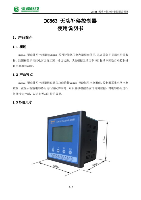
DC868智能低压电容器说明书
电器配件 低压辅助熔断器指南说明书
ContentsATC 1A5780ATM1A57781A5779Bussmann seriesFuses Made Simple TM - Control CircuitsFuse holder and block selection guideCatalog pages for the blocks and holders are denoted parenthetically "()" next to their catalog symbol.Cable limitersUH_—————Welder limiters6400068000RM60_ (8-21)————Bolt-on limiters ANNANL 4164 (2-4)4164-FR (2-4)————13/32" x 1-1/2" supplemental fuses BAFFNMFNQKLMKTKBMM603_ (8-6)3743 (8-14)4421 (8-14)4515 (8-14)CCP2-_ (11-2)OPM-1038_ (8-12)OPM-NG_ (8-13)CHM (8-8)NDNF1-WH (8-11)CCPLP†† (30 A) (11-32)HPC-D (8-43)HPD (8-44)HPF (8-43)HPG (8-44)HPM (8-44)HPM-D (8-44)HPS2 (8-45)HPS (8-45)HEB (8-51)HEX (8-53)1A3400_ (3-16)5960 (3-16)13/32" x 1-3/8" supplemental fuses BBS BMM603_ (8-6)—HPS-L (8-45)HEH (8-49)1A3400_ (3-16)5960 (3-16)Pin indication fuses and actuator GBAGLD——HLD (8-43)—1A1119 (3-15)1A1120 (3-15)1A1907 (3-15)1A3398 (3-15)1A4533 (3-15)1A4534 (3-15)5681 (3-16)5682 (3-16) MICFNABMM603_ (8-6)3839†—HPF-C (8-43)—1A3400_ (3-16)5960 (3-16)MIS fuseKAZ actuator2778†2837†2838†———1A3400_ (3-16)5960 (3-16)In-line size rejecting fuses GLQGMQ———HLQ (2-10)—In-line non-rejecting fuses GLRGMFGRF———HLR (2-11)HLR-2A (2-11)—Automotive blade-type fuses ATCATC-_IDFB_-ATC*15600*——ATC-FHID (2-14)HHC (2-14)HHD (2-14)HHF (2-14)HHG (2-14)HHR (2-14)HHS (2-14)1A5600 (2-14)1A5780 (2-14)ATMATM-_IDFB_-ATM*RTMF-_*——ATM-FHID (2-14)HHL (2-14)HHM (2-14)HHU (2-14)1A5778 (2-14)1A5779 (2-14)ATM-LP FB_-ATM*RTMF-_*——HHV (2-14)—ATR micro FB_-ATR*——HH2 (2-14)—MAXMAX-_IDHHX (2-14)MAX-FHID (2-14)* Not shown in this catalog, for details and available configurations, see Automotive and Home center catalog no. 5084.† Not shown in this catalog, see data sheet for details.†† UL 508 Listed disconnect switch, available in 1-, 2- and 3-pole versions.L o w v o l t a g e , s u p p l e m e n t a l f u s e sK 600 V cable limitersCable limiters for protecting 600 V low voltage distribution and service entrance cables against short-circuit currents.Ratings•Volts 600 Vac•IR 200 kA RMS Sym. @ 600 VacAgency information•UL Listed, File E90818, 600 Vac, 200 kA IR on catalog numbers CDA-W, CDB-W, KCD, KCJ, KCM, KCM-B, KCR, KDD, KDF , KDJ, KDM, KDP , KDR, KDU, KEW, KFM, KFT , KHF , KHJ, KHM, KHR Features•Sizes and ratings available to meet many applications* Copper conductors only.** C opper or aluminum conductors.1 UL Listed (File E90818), 600 Vac, 200 kA I.R.2 Available with shrink tube "-V" suffix.3 Available with molded rubber boots.4 Aluminum conductor only.Accessory boots (order separately)Recommended Thomas and Betts crimp tool TBM-14M with die 15506 KDM/15515 KDR for installation.UH 250 V cable limitersCable limiters for protecting 250 V low voltage distribution andservice entrance cables used in residential applications against short-circuit currents.Ratings•Volts Up to 250 Vac•IR 100 kA RMS Sym.T erminals and conductors•Center bolt-to-offset bolt terminals, Cu or Al conductors•Cu or Al conductors are permitted per the listed cable size. Select the catalog number for the conductor size. See data sheet 1042 for dimensions.UHJ-M 3/0250 kcmil UHJ-T 350 kcmil 500 kcmil UHJ-W600 kcmil800 kcmilData sheet no. 104264000 and 68000 600 V welder limitersLimiters for use on welder circuits. Note : welder limiters have special characteristics and are not suitable for use on other circuit types.Ratings•Volts 600 Vac (or less)•IR 200 kA RMS Sym.Features•Current-limiting devices designed specially for use only on welder circuits•Time-current characteristics are designed to hold on the intermittent overloading encountered in welder operation, while providing short-circuit protection to the circuit and equipment68600Class H 60064200Class J 20064300Class J300Recommended fuse blocks, see page 2-2.Data sheet no. 1042Data sheet no. 10454164 and 4164-FR limiter blocksLimiter fuse blocks for ANL and ANN. 4164 is furnished with nylon inserted locknuts and 4164-FR is furnished with standard hex nuts.Dimensions•L 3.38" x W 0.95" x H 1.62"•Studs center-to-center 2.43"Ratings•Volts 125 Vac, 80 Vdc, 32 Vdc (self certified) •Amps 10-800 A•Poles single, stud terminalData sheet no. 213341644164-FRANL/ANN limitersCircuit limiters typically used in fork lifts, marine, aviation and battery charging systems. ANL limiters are fast-acting and ANN limiters are very fast-acting. Both ANL and ANN limiters measure 7/8" x 3-3/16" (22x81mm) with a depth that varies by amp rating.Ratings•Volts•ANL 80 Vdc•ANN 125 Vac, 80 Vdc•Amps•ANL 35-750 A•ANN 10-800 A•IR•ANL 2700 A @ 80 Vdc•ANN 2500 A @ 125 Vac, 2700 A @ 80 VdcAgency information•ANL: UL Recognized, CSA Certified, 35-750 A @ 80 Vdc,IR 2700 A, Guide JFHR2, File E56412, Class 1422-30, File 53787, SAE J1171•ANN: UL Recognized, CSA Certified 35-400 A @ 125 Vac, IR 2500 A and 500 A @ 80 Vdc, IR 2700 A, Guide JFHR2, File E56412, Class 1422-30, File 53787, CE for 35-400 AANN-35ANN-100ANN-250ANN-500ANN-40ANN-125ANN-275ANN-600ANN-50ANN-150ANN-300ANN-700ANN-60ANN-175ANN-325ANN-800ANN-80ANN-200ANN-350Features•Fast-acting sizing for inductive circuits (ANL) •Very fast-acting circuit protection (ANN)•Element viewing window shows limiter status at a glanceFast-acting ANL Very fast-acting ANNData sheet no. 2023 (ANN), 2024 (ANL)BAF fast-acting 13/32" x 1-1/2" supplemental fuseFast-acting, supplemental fuse.Green color code (250 Vac max).For superior protection, Eatonrecommends upgrading toBussmann series Low-Peak ClassCC fuses. See data sheet no. 1023.Ratings1-1/2 to 2-1/2100 A10 kA—X3100 A10 kA X X4 to 10200 A10 kA X X12 to 15750 A10 kA X X20 to 30200 A10 kA——Agency information•UL Listed, Std. 248-14, 250 Vac (3 to 15 A) Guide JDYX,File E19180, CSA Certified, 250 Vac (1/4 to 15 A) Class 1422-01,File 53787BAF-1/2BAF-2BAF-6-1/4BAF-15BAF-6/10BAF-2-1/2BAF-7BAF-20BAF-8/10BAF-3BAF-8BAF-25BAF-1BAF-4BAF-9BAF-30BAF-1-1/2BAF-5BAF-10Features•Green color code for maximum 250 Vac rating•Fiber tube construction with nickel-plated brass endcapsT ypical applications•General purpose circuits•Lighting circuit protection•Meter circuitsRecommended blocks and holders for 13/32" x 1-1/2" fuses, seepage 2-2.KTK fast-acting 13/32" x 1-1/2"supplemental fuseFast-acting supplemental fuse.Black color code (600 Vac max).For superior protection, Eatonrecommends upgrading toBussmann series Low-Peak ClassCC fuses. See data sheet no. 1023.•UL Listed, Std. 248-14, Guide JDYX, File E19180, CSA Certified,C22.2 No. 248.14, Class 1422-01, File 53787, HRC-MISC, RoHScompliant, CEKTK-1/8KTK-1KTK-5KTK-15KTK-2/10KTK-1-1/4KTK-6KTK-20KTK-1/4KTK-1-1/2KTK-7KTK-25KTK-3/10KTK-2KTK-7-1/2KTK-30KTK-4/10KTK-2-1/2KTK-8KTK-1/2KTK-3KTK-9KTK-6/10KTK-3-1/2KTK-10Features•Black color code for 600 Vac rating•Fast-acting for resistive loads•Melamine tube construction with nickel-plated bronze endcapsT ypical applications•Control circuits•Lighting circuit protection•Meter circuitsRecommended blocks and holders for 13/32" x 1-1/2" fuses, seepage 2-2.Data sheet no. 2011 (0-30)Data sheet no. 10112011/65/EUKLM fast-acting 13/32" x 1-1/2" supplemental fuseFast-acting supplemental fuse.Color code black (600 Vac/dcmax). For superior protection,Eaton recommends upgrading toBussmann series Low-Peak ClassCC fuses. See data sheet no. 1023.For protecting PV systems, usePVM 10x30mm PV fuses. See datasheet no. 10121.RatingsElectrical characteristics135%AC opens within 1 hourAgency information•UL Listed, Std. 248-14, Guide JDYX, File E19180, CSA Certified,C22.2 No. 248. 14, Class 1422-01, File 53787, RoHS compliant, CEKLM-1/8KLM-1-1/4KLM-6KLM-20KLM-2/10KLM-1-1/2KLM-7KLM-25KLM-1/4KLM-2KLM-8KLM-30KLM-3/10KLM-2-1/2KLM-9KLM-1/2KLM-3KLM-10KLM-3/4KLM-4KLM-12Features•Color coded for 600 Vac/dc maximum•A full range DC performance fuse•Melamine tube construction with nickel-plated brass endcapsRecommended fuse blocks and holders for 13/32" x 1-1/2" fuses, see page 2-2.FNM time-delay 13/32" x 1-1/2" supplemental fuseTime-delay supplemental fuse.Color code green (250 Vac max).For superior protection, Eatonrecommends upgrading toBussmann series Low-Peak ClassCC fuses. See data sheet no.1023.Ratings1-1/8 to 3-1/2100 A10 kA X X4 to 10200 A10 kA X X12 to 3010 kA—X X Agency information•UL Listed, Std. 248-14, Guide JDYX; File E19180, CSA Certified, Class 1422-01, File 53787, RoHS compliant, CEFNM-1/8FNM-1FNM-2-8/10FNM-7FNM-15/100FNM-1-1/8FNM-3FNM-8FNM-2/10FNM-1-1/4FNM-3-2/10FNM-9FNM-1/4FNM-1-4/10FNM-3-1/2FNM-10FNM-3/10FNM-1-1/2FNM-4FNM-12FNM-4/10FNM-1-6/10FNM-4-1/2FNM-15FNM-1/2FNM-1-8/10FNM-5FNM-20FNM-6/10FNM-2FNM-5-6/10FNM-25FNM-3/4FNM-2-1/4FNM-6FNM-30 Features•Color coded for 250 Vac maximum•Melamine tube construction with nickel-plated brass endcapsT ypical applications•Circuits with high inrush currents (motor/transformer loads)•Supplemental protection for 125 Vac and 250 Vac inductive circuits Recommended fuse blocks and holders for 13/32" x 1-1/2" fuses, seepage 2-2.Data sheet no. 2020Data sheet no. 20282011/65/EU2011/65/EUFNQ time-delay 13/32" x 1-1/2" supplemental fuseTime-delay supplemental fuse.Color code orange (500 Vacmax). For superior protection,Eaton recommends upgrading toBussmann series Limitron FNQ-RClass CC fuses. See data sheet no.1014.RatingsAgency information•UL Listed, Std. 248-14, Guide JDYX, File E19180, CSA Certified,C22.2 No. 248.14, Class 1422-01, File 53787, HRC-MISC, RoHScompliant, CEFNQ-1/8*FNQ-1FNQ-3-1/2FNQ-10FNQ-15/100*FNQ-1-1/8FNQ-4FNQ-12FNQ-3/16FNQ-1-1/4FNQ-4-1/2FNQ-14FNQ-2/10FNQ-1-1/2FNQ-5FNQ-15FNQ-1/4FNQ-1-6/10FNQ-5-6/10FNQ-20FNQ-3/10FNQ-2FNQ-6FNQ-25FNQ-4/10FNQ-2-1/4FNQ-6-1/4FNQ-30FNQ-1/2FNQ-2-1/2FNQ-7FNQ-6/10FNQ-3FNQ-8* Not RoHS compliant.Features•Color coded for 500 Vac maximum•Fiber tube construction with nickel-plated brass endcapsT ypical applications•Motor control transformers•Circuits with in-rush currentsRecommended blocks and holders for 13/32" x 1-1/2" fuses, seepage 2-2.BBS fast-acting 13/32" x 1-3/8" supplemental fuseFast-acting supplemental fuse.Color codes black (600 Vac max1/10 to 6 A), green (250 Vac max7 to 10 A), purple (48 Vac max 12to 30 A). (For superior protection,Eaton recommends upgrading toBussmann series Low-Peak Class7 to 10—10 kA—X X12 to 30*—————* For interrupting rating, contact factory.Agency information•UL Listed, Std. 248-14 (1/10-6 A@600 Vac, 7-10 A@250 Vac), GuideJDYX, File E19180, CSA Certified, C22.2 No. 248.14 (1/10-6 A@600Vac, 7-10 A@250 Vac), Class 1422-01, File 53787, CEBBS-2/10BBS-1BBS-5BBS-20BBS-1/4BBS-1-1/2BBS-6BBS-25BBS-4/10BBS-1-6/10BBS-7BBS-30BBS-1/2BBS-1-8/10BBS-8BBS-6/10BBS-2BBS-10BBS-3/4BBS-3BBS-12Features•Color coded for 600 Vac (black) 250 Vac (green) and 48 Vac (purple)for maximum•Fiber tube construction with nickel-plated brass endcapsT ypical applications•Control circuits•Gaseous vapor fixtures•HID ballasts•Electronic circuits•Hand-held metersRecommended blocks and holders for BBS fuses, see page 2-2.Data sheet no. 1012Data sheet no. 20102011/65/EUGBA/GLD fast-acting 1/4" x 1-1/4" pin-indicating supplemental fuseFast-acting, pin-indicating fuse.Ratings•Volts — see agency information•Amps 1/2-15 A•IR — see agency informationAgency information•UL Listed, Std. 248-14, 0-5 A/125 Vac, 10,000 AIC, Guide JDYX, File E19180•UL Recognized, 6 A/125 Vac, 1000 AIC 8-15 A/50 Vac/dc, 300 AIC Guide JDYX2, File E19180•CSA Certified, 0-5 A/125 Vac, 10,000 AIC Class 1422-01, File 53787•CEGLD-3/4GLD-2GLD-5GLD-12GLD-1GLD-3GLD-6GLD-15 Features•Type GBA has a "red" pin indicator providing visual identification of failed circuits, resulting in faster troubleshooting (reduced circuit downtime)•Type GLD has a plated pin to activate transmitting a electrical signal to indicate the location of opened circuits, resulting in reduced downtimeT ypical applications•Control circuits•Electronic circuitsRecommended fuse blocks/fuse holders for 1/4" x 1-1/4" indicating fuses, see page 2-2.MIC fast-acting 13/32" x 1-1/2" pin-indicating supplemental fuseFast-acting, pin-indicatingsupplemental fuse. Green colorcode (250 Vac max 1 to 15 A), gray(32 Vac max 20 to 30 A).Ratings2 to 3100 A—X—5 to 10200 A—X—15750 A—X—20 to 30—10 kA——Electrical characteristics135% 1 hour max.Agency information•UL Listed, Std. 248-14, 1-15 A, Guide JDYX, File E19180, CEMIC-2MIC-8MIC-20MIC-3MIC-10MIC-25Features•Color coded by maximum voltage rating•Pin indication for visual indication of open fuse condition •Silver-plated pin for positive, electrical signal activation•Fiber tube construction with nickel-plated bronze endcapsT ypical applications•Power electronic circuits in which fuse opening must be quickly apparent•Control circuits•PLC CircuitsRecommended signal block for, 13/32" x 1-1/2" indicating fuses, seepage 2-2.Data sheet no. 10246 Data sheet no. 2012L o w v o l t a g e , s u p p l e m e n t a l f u s e sFNA time-delay 13/32" x 1-1/2" pin-indicating supplemental fusePin-indicating time-delay supplemental fuse. Color coded green (250 Vac max 1/10 to 6 A), blue (125 Vac max 6-1/4 to 15 A) and gray (32 Vac max 20 to 30 A).Ratings1 to 6200 A 10 kA —X X 6-1/4 to 15—10 kA —X X 20 to 30——1 kA——Agency information•UL Listed, 1/10 to 8/10 A @ 125/250 Vac, 1-15 A @ 125 Vac, Guide JDYX, File E19180, CSA Certified, 1/10 to 10 A @ 125 Vac, Class 1422-01, File 53787, CEFNA-1/8FNA-1-1/8FNA-3-2/10FNA-10FNA-15/100FNA-1-1/4FNA-3-1/2FNA-12FNA-2/10FNA-1-4/10FNA-4FNA-15FNA-1/4FNA-1-1/2FNA-4-1/2FNA-20FNA-3/10FNA-1-6/10FNA-5FNA-25FNA-4/10FNA-1-8/10FNA-5-6/10FNA-30FNA-1/2FNA-2FNA-6FNA-6/10FNA-2-1/4FNA-6-1/4FNA-3/4FNA-2-1/2FNA-7FNA-8/10FNA-2-8/10FNA-8Features•Color coded by maximum voltage rating•Pin-indication for visual indication of open fuse condition•Dual-element, time-delay performance permits close sizing on control transformers and relays•Silver-plated pin for positive, electrical signal activation•12 amp and more versions are dual-tube constructionRecommended signal block for 13/32" x 1-1/2" indicating fuses, seepage 2.2.MIS non time-delay 13/32" x 2" pin-indicating supplemental fuse and KAZ non-fuse pin-indicating actuatorMIS is a non time-delay pin-indicating fuse.KAZ is a non-fuse actuator mounted inparallel with fuses having a 50 amp or larger rating to provide blown fuse dropout for shunt-trip fused switches. To order, specify catalog number KAZ .RatingsAmps 1-12 A N/A IR200 kA200 kAMIS fuse electrical characteristics1-5 A 150% 6 min. (max.)6-12 A150%12 min. (max.)MIS-2MIS-4MIS-8MIS-12KAZ agency information•UL Listed, Guide JDVS, File E58836, CEMIS fuse features•Pin indicator provides visual identification of failed circuits,resulting in faster troubleshooting (reduced circuit downtime) •Fuse can be used in circuits rated 600 V or less•High 200 kA interrupting rating for high fault current circuitsMIS fuse typical applications•480 V control circuits•PLC circuitsKAZ actuator features•Convenient means to add open fuse signaling •Actuator can be used in circuits rated 600 V or less•High 200 kA interrupting rating for high fault current circuitsKAZ actuator typical applications•Large, shunt-trip fused switches•Fuse protected circuits rated 50 A or larger with shunt-trip devicesRecommended signal blocks for MIS and KAZ, see page 2-2.Dual-tube construction 12A and upData sheet no. 2029Data sheet no. 2021GLQ fast-acting, size-rejecting supplemental fuseFast-acting, size-rejecting in-line fuse. Match fuse and holder amp rating per catalog number table below.Ratings•Volts 300 Vac (or less) •Amps 1-10 A•IR 10 kAAgency information•UL Listed, Std. 248-14, (Guide JDYX, File E19180), CSA CertifiedC22.2 No. 248.14, (Class 1422-01,File 53787), CE 1 Carrier is UL Recognized, Guide IZLT2, File E14853 and CSA Certified, Class 6225-01, File 47235 10 A, 300 Vac.2 Units can be panel-mounted either in a knockout hole with a separate steel clip (BK/A-104) or in a keyhole punch using separate mounting clip NO.6374 for panels of thickness 0.043"to 0.062" or NO.4909 for thickness 0.030" to 0.042".Note: Do not put tension on line (rear) terminal of fuse holder.Features•In-line, fast-acting circuit protection•Rejection feature prevents overfusingT ypical applications•In-line lighting ballast protectionGMQ time-delay, size-rejecting supplemental fuseTime-delay, size-rejecting in-line fuse. Match fuse and holder amp rating per catalog number table below.Ratings•Volts 300 Vac (or less) •Amps 1/2 to 6-1/4 A•IR 10 kAAgency information•UL Listed, Std. 248-14, (Guide JDYX, File E19180), CSA Certified, (Class 1422-01, File 53787), CE1 Carrier is UL Recognized, Guide IZLT2, File E14853 and CSA Certified, Class 6225-01, File 47235 10 A, 300 Vac.2 Units can be panel-mounted either in a knockout hole with a separate steel clip (BK/A-104) or in a keyhole punch using separate mounting clip NO.6374 for panels of thickness 0.043"to 0.062" or NO.4909 for thickness 0.030" to 0.042"Note: Do not put tension on line (rear) terminal of fuse holder.Features•In-line, fast-acting circuit protection•Rejection feature prevents overfusingT ypical applications•In-line lighting ballast protectionHLQ fuse holders for both GLQ and GMQ fusesData sheet no. 2033Data sheet no. 2030L o w v o l t a g e , s u p p l e m e n t a l f u s e sGLR fast-acting, non size-rejecting supplemental fuseFast-acting, non-rejection, in-line fuse. All fuses use the same HLR or HLR-2A holders.Ratings•Volts 300 Vac (or less) •Amps 3/16-15 A•IR 10 kAAgency information•UL Listed, Std. 248-14, 0-15 A/300 Vac Guide JDYX, File E19180, CSA Certified C22.2, No. 248-14, 0-10 A/300 V Class 1422-01, File 53787, CE1 Carrier is UL Recognized, Guide IZLT2, File E14853 and CSA Certified, Class6225-01, File 47235 12 A, 300 Vac.2 Units can be panel-mounted either in a knockout hole with a separate steel clip (BK/A-104) or in a keyhole punch using separate mounting clip NO.6374 for panels of thickness 0.043"to 0.062" or NO.4909 for thickness 0.030" to 0.042".* For two leads (one each for line and loadside) order HLR-2A, 15 A, 300 V Note: Do not put tension on line (rear) terminal of fuse holder."A" in-line holderAn alternative to the HLR fuse holder is the "A" fuse holder. The A fuse holder comes WITHOUT leads. The customer inserts NO.18 insulated solid copper wire into the lineside receptacle as well as into the load side receptacle. It has the same body dimensions,utilizes the same mounting hole, and takes the same mounting clips as the HLR. The A fuse holder is UL Recognized, 10 A, 300 Vac, Guide IZLT2, File E14853 and CSA Certified, 10 A, 300 Vac, Class 6225-01, File 47235. Order catalog number A.Features•In-line, fast-acting circuit protection.T ypical applications•In-line lighting ballast protectionGMF/GRF time-delay, non size-rejecting supplemental fusesTime-delay, non-rejection, in-line fuse. All fuses use the same HLR or HLR-2A holders.Ratings•Volts 300 Vac (or less) •Amps 3/10-10 A•IR 10 kAAgency information•UL Listed, Std. 248-14 0-10 A, Guide JDYX, File E19180, CSACertified, Class 1422-01, File 53787, CE6225-01, File 47235 12 A, 300 Vac.2 Units can be panel-mounted either in a knockout hole with a separate steel clip (BK/A-104) or in a keyhole punch using separate mounting clip NO.6374 for panels of thickness 0.043"to 0.062" or NO.4909 for thickness 0.030" to 0.042".* For two leads order HLR-2A, 15 A, 300 VNote: Do not put tension on line (rear) terminal of fuse holder."A" in-line holderAn alternative to the HLR fuse holder is the A fuse holder. The A fuse holder comes WITHOUT leads. The customer inserts NO.18 insulated solid copper wire into the line side receptacle as well as into the load side receptacle. It has the same body dimensions,utilizes the same mounting hole, and takes the same mounting clips as the HLR. The A fuse holder is UL Recognized, 10 A, 300 Vac, Guide IZLT2, File E14853 and CSA Certified, 10 A, 300 Vac, Class 6225-01, File 47235. Order catalog number A.Features•In-line, time-delay circuits protectionT ypical applications•In-line lighting ballast protectionHLRfuse holderData sheet no. 2032Data sheet no. 2031HLR-2A fuse holderATM and ATM-LP fast-acting blade fusesFast-acting, color-coded blade fuse available in standard and low-profile versions. Standard version available with indication.Ratings•Volts 32 Vdc •Amps 1-30 A•IR 1000 AAgency information•UL Listed, Guide FHXT, File AU 169 (2-30 A non-indicating ATM)ATM-2—ATM-2LP Gray ATM-3ATM-3ID ATM-3LP Violet ATM-4—ATM-4LP Pink ATM-5ATM-5ID ATM-5LP Tan ATM-7-1/2ATM-7-1/2ID ATM-7-1/2LP Brown ATM-10ATM-10ID ATM-10LP Red ATM-15ATM-15ID ATM-15LP Blue ATM-20ATM-20ID ATM-20LP Y ellow ATM-25ATM-25ID ATM-25LP Clear ATM-30ATM-30IDATM-30LPGreen* Call customer satisfaction for ordering information.Features•Industry standard color coding for easy identification of fuse rating•Indicating versions show blown fuse at a glance, speeds troubleshootingT ypical applications•AutomotiveRecommended blocks and holders for ATM fuses, see page 2-14.ATR fast-acting micro blade fuseFast-acting, color-coded 2-leg micro blade fuse.Ratings•Volts 32 Vdc •Amps 5-30 A•IR 1000 AAgency information•RoHS compliant ATR-7-1/2Brown ATR-25Clear ATR-10Red ATR-30GreenATR-15BlueFeatures•Space-savings size•Industry standard color coding for easy identification of fuse ratingT ypical applications•AutomotiveRecommended holder for ATR fuses, see page 2-14.Low-profileStandardIndicatingData sheet no. 2048 (ATM), 2050 (ATM-LP)2011/65/EUMAX (MAXI) fast-acting blade fuseFast-acting, color-coded, high amp blade fuse. Available with and without indication.Ratings•Volts 32 VdcMAX-25—Gray MAX-30MAX-30ID Green MAX-35—Brown MAX-40MAX-40ID Orange MAX-50MAX-50ID Red MAX-60MAX-60ID Blue MAX-70MAX-70ID Tan MAX-80MAX-80ID Clear —MAX-100IDPurple* Call customer satisfaction for ordering information.Features•Color coded housing for easy identification of fuse rating•Indicating versions show blown fuse at a glance, speeds troubleshootingT ypical applications•AutomotiveRecommended holders for MAX fuses, see page 2-14.ATC fast-acting blade fuseFast-acting, color-coded blade fuse for automotive and control circuit applications.Ratings•Volts 32 Vdc •Amps 1-40 A•IR 1000 AAgency information•UL Recognized, (1-40 A) (Guide JFHR2, File E56412), SAE Standard J1284ATC-2—GrayATC-3ATC-3IDViolet ATC-4—Pink ATC-5ATC-5ID Tan ATC-7-1/2ATC-7-1/2ID Brown ATC-10ATC-10ID Red ATC-15ATC-15ID Blue ATC-20ATC-20ID Y ellow ATC-25ATC-25ID Clear ATC-30ATC-30ID Green ATC-35ATC-35ID Blue-green ATC-40ATC-40IDOrange* Call customer satisfaction for ordering information.Features•Industry standard color coding for easy identification of fuse rating•Indicating versions show blown fuse at a glance, speeds troubleshootingT ypical applications•Automotive•Low voltage control circuitsRecommended blocks and holders for ATC fuses, see page 2-14.StandardIndicatingData sheet no. 2009Data sheet no. 2049In-line fuse holders for ATM, ATC and MAX fusesPCB fuseclips for ATM and ATC fusesATM fuseclips Catalog no. 1A5778•15 A•Nickel-plated brassDimensions — mm (in)Land patternCatalog no. 1A5779•15 A•Nickel-plated brass/glass-filled nylonDimensions — mm (in)ATC fuseclips Catalog no. 1A5600•20 A•Tin-plated cartridge brassDimensions — in (mm)Catalog no. 1A5780•15 A•Nickel-plated brass/glass-filled nylonDimensions — mm (in)Land patternData sheet no. 2131In-line fuse holders for ATM, ATC and MAX blade fuses. Versions available with and without covers and with open fuse indication.Ratings•Volts 32 Vdc•Amps 80% continuous of fuse rating. See catalog numbers tablefor individual holder fuses amp ranges.MAX-FHID Indicator, black w/ cover602x5" #6 red leadwire Fuses must be fully inserted into the holder to provide a solid connection. Poor or improper fuse insertion can result in fuse and holder failure and loss of power and/or circuit protection.Typical in-line blade fuse holders with leadwireseasy ID LED indicating holders available for ATM, ATC and MAX fusesData sheet no. ATM fuses 2128 (HHM, HHL) ATC fuses 2107 (HHC, HHD, HHF , HHG) Max fuses 2129 (HHX)。
DC-868智能电容器使用说明书
科技创新、节能环保1目录一、 产品概述二、 产品型号规格和说明1、 型号说明2、 常规产品的型号规格三、 产品外形与安装尺寸 四、 接线端子排列与定义 五、 产品应用电气连接及接线1、 三相共补接线图2、 混合补偿接线图六、 显示面板定义说明 七、 开机前的检查与试验 八、 操作说明1、 数据查看2、 参数设定科技创新、节能环保2九、 查看数据界面1、 三相共补式数据查看说明2、 单相分补式数据查看说明十、 参数设定界面1、 三相共补式参数设定说明2、 单相分补式参数设定说明十一、 常见故障分析1、 通电后产品数码管暗或无显示2、 PF 值显示负值3、 故障指示灯亮科技创新、节能环保3一、 产品概述DC868系列低压智能电容器是应用于0.4kV 低压电网的新一代无功补偿装置。
它由CPU 测控单元、同步开关、保护装置、两台(△型)或一台(Y 型)低压自愈式电力电容器组成一个独立完整的智能补偿单元,替代由智能无功控制器、熔丝(或微断)、晶闸管复合开关(或接触器)、热继电器、指示灯、低压电力电容器多种分散器件组装而成的自动无功补偿装置。
由DC868系列智能电容器组成的低压无功补偿装置具有补偿方式灵活(共补和分补可任意组合)、补偿效果好、装置体积小、功耗低、价格廉、安装维护方便、使用寿命长、保护功能强、可靠性高等特点,并真正做到过零投切,满足用户对无功补偿要切实达到提高功率因数、改善电压质量、节能降损的实际需求。
科技创新、节能环保4二、 产品型号说明1、 型号说明DC∕450二级容量(kvar )分相补偿只有一级容量 一级容量(kvar) 额定电压(V )显示方式:Y-液晶显示 数码显示无字母 补偿方式:S-共补 F-分补 组网方式:R-RS485 L-蓝牙W-无线 产品系列号:868-通用型868X-抗谐波型企业代号:得诚科技创新、节能环保52、常规产品型号规格科技创新、节能环保6三、 产品外形及安装尺寸注:高度尺寸见表1科技创新、节能环保7四、 接线端子排列与定义产品的接线端子分电源端子和测控联机端子,均置于产品的后部,三相补偿电源端子有“UA.UB.UC ”,分相补偿电源端子有:“UA.UB.UC.UN ”,测控联机端子使用插拔件,便于现场调试和调换,产品上有“1.2.3.4.5.6.7.8.9.10.11”,序号标志,其中6—11是标准的6针水晶头接口,两个并接,接线或调换时应充分注意。
智能电容控制器说明书-A

3.运行工况界面运行工况里包含了配电电压、电流、功率因数、功率、电压各次谐波、电流各次谐波等各电参数的数值显示,以及测控仪与智能电容器的通信状况,通过“或”键切换界面查看各电参数以及测控仪与智能电容器的通信状况,按“”键返回到主菜单界面。
以下细分界面依次对各项进行介绍:(1)配电三相功率因数、电压、电流界面在使用过程中若出现过补偿或配电电流接线接反,则在上述界面中功率因数数值前显示‘-’,例如A相功率因数显示‘-0.960’,表示此时A相电容已过补偿或A相配电电流方向接反。
在使用过程中若出现过压或欠压现象,在上述界面中电压反显显示,例如A相电压显示“”,表示此时A相电压已超过设定过压值。
(2)有功、无功、电容电流界面P(KW) :实时的有功功率;Q(Kvar):系统当前过补偿或欠补偿的无功数值;C-I(A) :实时的电容器电流值。
(3)通信界面测控仪与不同的智能电容器通讯,其显示的通信界面略有不同,如下图所示:图1 图2图3图1为测控仪与三相式智能电容器或智能抑谐式电容器(双电容电抗)通信界面;图2为测控仪与三相式智能抑谐式电容器(单电容电抗)的通信界面;图3为测控仪与分相式智能电容器的通信界面;“JH C1 C2”中“JH”表示三相式智能电容器的地址,“C1 C2”分别表示内部两组电容器的容量(如图所示“060 20.20”表示此三相式智能电容器地址为“60”,容量为20 Kvar +20Kvar)。
“JH C”中“JH”表示三相式智能抑谐式电容器(单电容电抗)的地址,“C”表示电容器的容量(如图所示“060 40”表示此三相式智能抑谐式电容器(单电容电抗)地址为“60”,容量为40 Kvar)。
“JH A B C”表示分相式智能电容器的地址及A、B、C三相容量(如图所示“06 6.6 6.6 6.6”表示此分相式智能电容器地址为6,电容器容量为20Kvar)。
智能电容器投入后,状态反显显示。
PCS-9631D_X_说明书_国内中文_国内标准版_X_R1.24

南京南瑞继保电气有限公司
技术支持,请联系: 电话:025-52107703、8008289967、4008289967 传真:025-52100770 或登陆网站:/ser_sup
公司总部:南京市江宁区苏源大道 69 号,邮编 211102 生产地址:南京市江宁区新丰路 18 号,邮编 211111 公司网址:
残余电压 在装置电源关闭后,直流回路中仍然可能存在危险的电压。这些电压需在数秒钟后才会消失。
警示!
接地 装置的接地端子必须可靠接地。
运行环境 该装置只允许运行在技术参数所规定的大气环境中,而且运行环境不能存在不正常的震动。
额定值 在接入交流电压电流回路或直流电源回路时,请确认它们符合装置的额定参数。
警告!
为增强或修改现有功能,装置的软硬件均可能升级,请确认此版本使用手册和您购买的产品相 兼容。
警告!
电气设备在运行时,这些装置的某些部件可能带有高压。不正确的操作可能导致严重的人身伤 害或设备损坏。
只有具备资质的合格专业工作人员才允许对装置或在装置临近工作。工作人员需熟知本手册中 所提到的注意事项和工作流程,以及安全规定。
PCS-9631D 电容器保护装置
技术和使用说明书
前言
PCS-9631D 电容器保护装置
使用产品前,请仔细阅读本章节!
本章叙述了使用产品前的安全预防建议。在安装和使用时,本章内容必须全部阅读且充分理解。 忽略说明书中相关警示说明,因不当操作造成的任何损害,本公司不承担相应责任。
在对本装置做任何操作前,相关专业人员必须仔细阅读本说明书,熟悉操作相关内容。 操作指导及警告
我们对本文档及其中的内容具有全部的知识产权。除非特别授权,禁止复制或向第三方分发。凡侵犯本公司版权等知识产权的,本公司必 依法追究其法律责任。 我们定期仔细检查本文档中的内容,在后续版本中会有必要的修正。但不可避免会有一些错误之处,欢迎提出改进的意见。 我们保留在不事先通知的情况下进行技术改进的权利。
TDS93系列智能式低压电力电容器技术说明书

UA UB UCUo快速断路器 总电源接入端、总 开关,电流速切总保护。
智 能 组 件智能组件智能化载体。
配电电压测量和配电功率因数测 量的电压取样,以及过压、欠压、 失压保护取样。
零投切开关电器组件 投、退电 容器开关以及电容器过压、欠压、 失压、过流、断相、三相不平衡、 过温等保护出口。
微型CT 电容器电流测量取样以 及电容器过流、断相、三相不平衡 保护取样。
微型温度传感器 电容器温度测 量与保护取样。
低压电力电容器 容性负载,补 偿配电线路中的感性负载。
液晶显示屏与按键 用。
人机对话之2 4联机接插件 相互之间或与外设 之间联机之用,构成系统工作。
配电CT输入插件 配电电流取样。
TDS 13企业 企业 代号 产品 编号( ).()接线方式 C 安装方式 W 面板形式接线式 插件式 立式安装 卧式安装 一体式 F 分离式第2台电容器额定容量(kvar) 第1台电容器额定容量(kvar) 无抗谐波能力 抗谐波能力 (X) Z Z(Z) 控制方式 Z(L) J 有抗谐波能力 自动控制方式(RS-485通信接口) 自动控制方式(小载波通信模块) 自动控制方式(蓝牙通信模块) 接受控制方式(RS-485通信接口)额定电压(V)J(J) 接受控制方式(接点输出) S 补偿方式 F 三相补偿方式 分相补偿方式BAC0255075100125失效率(%)0255075100125衰减率(%)。
DC863无功补偿控制器说明书
注:
表示分补 表示共补
3/7
DC863 无功补偿控制器使用说明书
表示投入 表示切除
3.2 运行工况
显示开关故障、过压保护、过流保护、过温保护、过谐波保护的电容器信息。
使用 和
3.3 设置参数
切换界面查看各种保护与故障,按
键返回主菜单。
设置现场的电流互感器变比和无功控制的目标功率因数,如果现场互感器变比值不详可以 选择“自动检测 CT„”,自检 CT 必须保证至少有 1 台电容器和控制器联网,如果选中“自动
DC863 无功补偿控制器使用说明书
4.3 DC863无功补偿控制器接线端口说明
Ua,Ub,Uc分别接A,B,C三相电压,Un接零线; Ia+,Ia-,Ib+,Ib-,Ic+,Ic-分别接A,B,C三相电流; A,B为备用485通信接口;
7/7
尺寸
3 、使用说明
DC863 无功补偿控制器使用说明书
分辨率 128×64,显示 12 点阵汉字 RJ45 方式接入智能电容器网络 AC 380V±30% ≤2W -10~55 ℃,相对湿度≤93% 无腐蚀气体场所,海拔≤2000m 电源>2500V ≥2MΩ 面框尺寸:120mm×120mm 开孔尺寸:113mm×113mm
DC863 无功补偿控制器通过通信总线连接DC868 智能低压电容器组;控制器采集电网电测 数据,在显示智能电容器组运行情况的同时,可以直接根据当前的电测数据,对电容器组进行 智能投切控制,以达到无功补偿的效果。
1.3 外观尺寸
1/7
2
工作范围 功耗
工作条件
隔离耐压 绝缘电阻
投切状态
所有电容器投切状态总览
运行工况
智能低压无功补偿控制器使用说明书
目录一.产品概述 (1)二.功能特点 (1)三.使用环境 (2)四.技术参数 (2)五.安装与接线 (2)六.操作与运行 (5)七.系统调试 (12)八.常见现象分析 (14)九.售后服务 (15)一.产品概述智能无功补偿控制器(以下简称控制器)是本公司在吸收了国内外多个无功自动补偿控制器技术的基础上研发出来的新一代产品,款式新,功能全,安装使用灵活,全中文液晶菜单,操作方便。
控制器具有RS-485通讯接口,与本公司生产的智能低压电力电容器配套使用,接线简洁,运行可靠。
二.功能特点1.参数设置功能1)过压值、欠压值、欠流值等保护定值的设置;2)延时时间、投入、切除门限等投切限值的设置;3)取样电流互感器变比的设置。
2.测量功能1)取样互感器极性自动判别,接入时无需考虑极性要求;2)配电电压、电流、功率因数、有功功率、无功功率测量。
3.控制功能1)自动、手动控制电容器的投切。
自动控制时,根据受控物理量-无功功率进行投切;2)容量相同的电容器按循坏投切方式工作,容量不同的电容器按无功缺额进行编码投切;3)最多可同时控制32台智能低压电力电容器。
4.保护功能配电系统过电压保护、过电压闭锁、欠电压保护、欠流保护、缺相保护。
5.信号功能1)各台电容器投运、退运状态信号显示,各台电容器容量信号显示,各台电容器温度信号显示;2)配电参数越限信号(过压、欠压等)显示;3)控制器本身或电容器故障显示。
三. 使用环境工作温度: -20℃-60℃ 相对湿度: ≤90%(20℃) 大气压力: 79.5-106.5kpa 海拔高度: ≤3000m无易燃易爆的介质存在,无导电尘埃及腐蚀性气体存在。
四. 技术参数额定电压: 交流50Hz ,380V ±20% 电流取样: ≤5A 额定频率: 50Hz ±5% 净重:约0.8kg五. 安装与接线1.安装在屏柜上开113*113mm 的方孔,将本产品从屏前推入方孔内,把配给的紧固件插入安装槽中,上紧即可固定在屏上。
(UP-SC380)智能低压电容控制器使用说明书

UP-SC380智能电容控制器使用说明书(2014年1月版)恩联(北京)电气设备有限公司Union Power(Beijing) Electrical Equipment Co., Ltd.目录1. 概述 (3)2. 功能特性 (3)2.1 基本功能 (3)2.2 技术参数 (3)3. 外形结构 (5)4.端子接线 (6)4.1 智能电容控制器端子接线图 (6)4.2 端子接线说明 (6)5. 按键及显示 (7)5.1 面板及按键 (7)5.2 实时数据显示 (7)1. 概述智能电容控制器是一种与智能电容器配合使用的电力监控仪,它可以集中显示多组智能电容的投切状态,进行智能电容器投切测试,并且能够与DTU通信实现自动化功能。
该仪表可广泛应用于工矿企业、民用电力系统的配电装置及各类配电室、箱变、低压综合控制柜中,是配电自动化系统的系列产品之一。
本仪表符合《DL/T597-1996低压无功补偿控制器订货技术条件》等标准要求。
2. 功能特性2.1 基本功能智能电容控制器集配电变压器低压侧三相电气参数测量、记录、控制和通信等功能于一体,其主要功能包括:(1)实时显示电容的投切状态;(2)能够实现投切测试;(3)通信功能,上行与DTU通信,下行与智能电容通信;(4)参数集中设置。
2.2 技术参数(1) 工作电源:(85~265)VAC或(100~300)VDC(2) 通信功能:通信口具有RS-485通信方式。
通信规约:MODBUS通信规约。
波特率:(600~38400)bps 可选。
(3) 机械性能:外形尺寸:宽×高×厚:160mm×160mm×113.59mm。
重量:2.1kg。
(4) 运行环境:工作环境温度:-25℃~+75℃;相对运行湿度:20%~90%。
相对湿度<85%时采取特殊措施可运行在-35℃环境内。
耐受污秽等级IV级。
谐波含量〈20%。
海拔2000米及以下。
YBD868说明书-中文

YBD868数字集成电路测试仪说明书(使用前请详细阅读此说明书)目录第一部分简介一.概述二.整机及配件三.技术指标四.测试范围五.功能综述六.维护保养第二部分操作说明一.自检二.操作说明第三部分可测器件清单第一部分简介一.概述YBD868型数字集成电路测试仪是一种性能较高的通用仪器,测试脚数量最大为双列直插式40脚,可测范围覆盖了大多数的数字集成电路,测试准确可靠,操作简便,基本功能如下:* 器件好坏测试* 器件型号判别* 器件动态老化* 器件代换查询YBD868型数字集成电路测试仪以先进的微处理器为核心,主要器件选用INTEL,MOTOROLA等著名器件公司出产的集成电路,配合软件和外围扩展系统来全面模拟被测器件的综合功能,几乎适合于所有具有固定输出的数字集成电路。
广泛用于维护,检测各类计算机,工业自动化设备,大型医疗仪器,数控机床,微机外围设备,程控交换机,电子仪器仪表,数字通讯设备,电子继电保护装置及各类电子产品。
二.整机及配件1.YBD 868型数字集成电路测试仪一台2.电源线一根3.特殊器件测试板一块4.说明书一本5.保修卡一张三.技术指标1.操作系统:十六位轻触式立体键盘双音提示系统,被测器件安装采用锁紧插座。
2.显示系统:六位数码管显示器显示被测器件型号或各种功能提示,四只LED显示仪器工作状态。
3.电源电压:220V±10%, 50HZ4.整机功耗:12VA5.适用温度:0℃--+40℃6.工作时间:工作1小时停电5分钟。
若连续工作,电源电压∠230V,环境温度∠25℃。
7.仪器结构:台式塑料机箱8.外形尺寸:292*235*75立方厘米9.整机重量:2.0KG四.测试范围YBD868型数字集成电路测试仪库存容量两千多片,包含以下各大系列:1.TTL54系列2.TTL55系列3.TTL74系列4.TTL75系列5.CMOS14系列6.CMOS40系列7.CMOS45系列8.光耦合器系列9.LED显示器系列10.常用RAM系列11.常用单片机系列12.微机外围电路系列五.功能综述1.器件好坏判别:当未知被测器件的好坏时,只要输入该器件的型号,并将器件放于对应的工作插座上,仪器即可判别出该器件的好坏。
低压电容器说明书
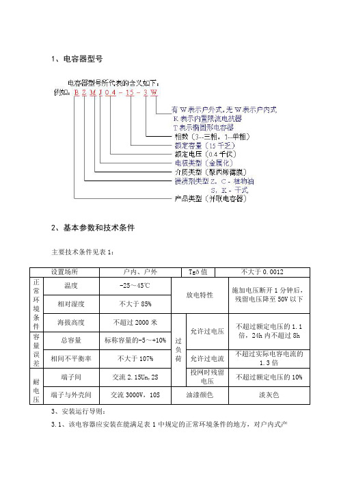
1、电容器型号2、基本参数和技术条件主要技术条件见表1:3、安装运行导则:3.1、该电容器应安装在能满足表1中规定的正常环境条件的地方,对户内式产品来说,还要求装设电容器的地方不受阳光的直射、不被雨雪淋湿、无腐蚀性气体、无盐碱、金属粉末及尘埃少、机械震动小,并且通风良好。
3.2、当许多电容妻集中安装在某一部位,或者和其他易发热的设备一起安装在某一部位时,该部位的环境温度将会超过电容器允许工作环境温度的上限,这时,必须充分考虑有效的通风散热措施。
3.3在下列情况下,电容器有能处在过电压状态下运行:(1)电容起的接入可能会引起网路电压的升高,因此电容器容易在比其接入前测得的更高电压下运行。
(2)网路的实际电压可能高于其标准电压。
(3)由于串入电抗器,会引起电容器上的电压升高。
因此,必须在充分考虑了上述因素的前提下,来判定网路的实际电压是否与电容器额定电压相同,确保电容器线路端子上的实际电压不超过表1规定的电压值。
3.4在轻负荷时,由于接入电容器,使功率因素显著超前而容易产生过电压,这时,应将部分和全部电容器从线路中切除。
3.5电容器与感应电动机并接,并且共用一个开关开断时,由于自激现象容易产生过电压,在这种情况下,可按照电容器电流小于电动机空载(建议为90%左右)的原则来选配电容器容量。
3.6在安装电容器前后,必须注意检查测量电压波形和网路特性,如果存在谐波源(如大型整流器),则应考虑采取下列措施来降低有谐波引起的过电流:(1)将部分和全部电容器移到其他系统中去;(2)在电容器上串接适当的电抗器,以将回路的某一高次谐波降至干扰频率下;(3)在大型整流器近旁,增设滤波电容器;(4)如果存在超过规定值的谐波,将大大降低电容器的使用寿命,因此必须采取措施来消除谐波。
3.7在已经接入电容器的情况下,新的电容器投切时会产生很大的过渡过电流(涌流)考虑到电容器和其他设备仪器的容许值,此时应串接限流电抗器或采用带限流元件的接触器,将过渡过电流峰值限制在100In(额定电流有效值)以下。
低压说明书

目录1 前言 12 使用条件 13 主要技术指标 14 型号、外型尺寸及重量 25 设备功能 26 设备构成 47 安装调试 58 使用操作 69 维护 910 附图 12前言使用条件主要技术指标1.前言目前, PLC 可编程序控制器已在工业化领域得到广泛的应用。
世界主要PLC生产厂商,如SIEMENS、OMRON、MODICON 和AB 等公司竞相推出各种系列产品。
大连电子研究所早在八十年代中期就开始在电除尘低压程控系统及其它工业过程控制中采用PLC可编程控制技术。
先后用过SIEMENS公司(S5,S7系列)MODICON公司(984,COMPACT984及QUANTUM系列)OMRON公司C200,CQM1系列)AB公司(S500,S5000系列)的产品设计生产了数百套程控设备。
目前已形成了DDPLC系列程控柜(为除尘器设备配备),主要控制对象包括阴、阳极振打电机,分布板,槽板振打电机,瓷套,瓷轴电加热器,卸灰电机等设备(具体的控制设备及方式可根据用户的要求实现,可另行增加所需要控制的设备)。
可按用户要求选用其它类型PLC控制器。
2.使用条件2.1海拔高度:不超过2000米。
2.2环境温度:-10℃~ +55℃。
2.3相对湿度:不大于90%(20±5℃)。
2.4无腐蚀性气体和导电尘埃。
2.5无剧烈振动。
3.主要技术指标3.1动力回路电源:三相交流 380V±10%,50Hz。
功率:根据所选设备容量决定。
(详见高低压配套图)3.2控制回路电源:单相交流 220V±10%,50Hz。
功率:小于0.5kVA。
3.3PLC控制器输出(取于控制回路):直流型——DC24V/0.5A经中间继电器转换为AC220V/2A。
交流型——AC220V/2A。
3.4击穿电压: AC端与框架接地点之间1500V有效值1 分钟。
DC端与框架接地点之间500V有效值1分钟。
3.5 绝缘电阻:最小100MΩ。
DC868RS和DC868RF常规型智能低压电容器
DC868RS/DC868RF常规型智能低压电容器产品概述DC868系列智能低压电容器集成了现代测控、电力电子、网络通讯、自动化控制、自愈式电力电容器等先进技术,由智能测控模块、过零投切模块、保护模块、智能通信模块、人机对话模块、电力电容器等组成,替代传统的由控制器、熔丝、复合开关或机械式接触器、热继电器、低压电容器、指示灯等分离器件在柜内用导线连接而组成的成套无功补偿装置。
智能低压电容器组成的低压无功补偿装置,具有补偿方式灵活(三相补偿和分相补偿可任意组合,集中补偿和本地补偿灵活选择)、补偿效果好、装置体积小、功耗低、价格低廉、安装维护方便、使用寿命长、保护功能强、可靠性高等特点,并真正做到过零投切,满足用户对设备的实际需求,适应了现代电网对无功补偿设备的更高要求。
产品功能■等位通讯技术多台智能低压电容器通过RS485接口组成等位智能通讯系统,随机产生一台主机(也可手动设置),其余的设备为从机。
无论任何主从机发生故障,都可自动退出运行,剩余设备组成新的网络正常运行。
系统可以将电容按需投切,容量相同的电容器采用循环投切原则,避免对同一台反复投切影响其寿命。
■过零投切技术采用先进微电子软硬件技术,将DSP测控单元与三相同步开关完美结合起来,实现对低压电力电容器的等电压投入、电流过零切除。
当DSP测控单元接收到投入信号时,先检测电容器端电压与电源电压差,当电源电压与电容器电压相等时投入电容器,以减小涌流,降低对电容器的冲击;当DSP测控单元接收到切除信号时,先检测电容器电流接近为零时再切除电容器。
利用过零投切技术达到投入无涌流,切除无拉弧,触点不粘合,提高电容器的使用寿命,同时也减少涌流对电网的污染和冲击。
■无功补偿容量灵活配置DC868系列智能低压电容器是根据配电网功率因素和无功功率等判据进行自动投切、动态补偿无功功率、改善电能质量的新型无功补偿设备。
常规型设备内有两组电容器,可以实现多级自动补偿,补偿更精细;多台联机构成系统使用,可以本地补偿,也可以集中补偿。
低电压治理装置技术原理介绍

低电压治理装置技术原理介绍1.1 技术原理●设备组成DC52支线末端电压补偿装置主要由主控模块、电压补偿模块、无功补偿模块、通讯模块(选配)、主站系统(选配)等组成。
主控模块采用的是先进的电力电子技术对采样的电压、电流、功率因数等参数进行综合计算,使设备实现自动运行的同时还具有一系列的保护功能,加强了设备的使用寿命也避免了人工操作的麻烦。
电压补偿模块的核心器件为特制的调压器。
器件铁芯采用的是高导磁硅钢片,磁通密度取值低,铁损小;线圈采用优质导线制作,电流密度取值低,铜损小。
设备长期挂网运行,电能损耗低。
电压补偿模块的调压范围大,调节档位可根据现场工况进行定制,操作方便,维护简单,使用寿命长,与无功补偿模块相互配合,改善低电压效果显著。
无功补偿模块采用的是DC868系列智能低压电容器,集成了现代测控、电力电子、网络通讯、自动化控制、自愈式电力电容器等先进技术,由智能测控模块、过零投切模块、保护模块、智能通信模块、人机对话模块、电力电容器等组成,具有智能控制与过零投切功能,补偿精度高,使用寿命长。
通讯模块可以采集设备输入电压、输出电压、输入电流、输出电流、故障信息、功率、功率因数等数据,并将采集到数据经过GPRS通讯网络发送给主站系统。
通过通讯模块可以进行远程数据采集、监控和维护,节省大量的人力物力,提高工作效率。
●工作原理设备相线串接、零线并接在低压末端线路中,实时检测设备的输入电压Ui (即线路抬升前电压)与输出电压Uo。
当输入电压Ui过低时,电压补偿模块根据实际输入电压的数值投入相应的抬升电压,使输出电压Uo满足负载正常工作,并且智能电容器根据实际需要投入运行,用以降低因无功电流造成的线路压降。
当192V≤Ui≤204V时,主控模块控制电压补偿模块抬升12%电压,实现输出电压Uo在215V~228V之间;当165V≤Ui≤192V时,主控模块控制电压补偿模块抬升20%电压,实现输出电压Uo在198V~230V之间;当Ui≥204V或Ui≤155V或故障时,主控模块控制电压补偿模块进入旁路状态,设备处于通路状态,即输入电压Ui等于输出电压Uo。
正泰BAGB智能电容器使用说明书

BAGB 智能组合式低电压并联电容器使用说明书一、产品概述BAGB 系列智能式低电压并联电容器(简称智能电容器)是 0.4KV 低压配电网高效节能、降低线损、提高功率因数和电能质量的新一代无功补偿设备。
它由智能测控单元,过零投切开关电路,线路保护单元,低压电力电容器构成。
主要适用于农网建设、小区楼宇建设等谐波含量在国家标准范围内的电力系统。
该产品改变了传统无功补偿装置体积庞大和笨重的结构模式,从而使新一代低压无功补偿设备具有补偿效果更好、体积更小、功耗更低、价格更廉、使用更加灵活、维护更加方便、使用寿命更长、可靠性更高的特点,适应了现代电网对无功补偿的更高要求。
二、功能特点2.1操作简便:只要外部接线正确,选择好从机的地址,通电后就可运行,不需要任何设置。
2.2多台串联简单:不管从机退出或挂接均不影响主机运行。
只要从机挂接,马上会被主机联机进入补偿列内,无需任何条件。
2.3抗干扰能力强:采用弱电与强电分离进线,防止一次线对二次信号线的干扰,极大地提高了整机的抗干扰能力。
2.4防止倒送无功危害:采用永久性故障跳闸保护装置。
一旦智能电容器如发生不可修复故障将自动跳闸,退出电网,防止因故障对电网的倒送无功危害,保证无功补偿系统的正常运行。
2.5投切涌流小:采用先进的过零投切技术,大大减少对电网的冲击。
2.6具有自检功能:可以模拟自动运行投切,电容柜生产厂通过自检功能即可做出厂试验,无需专用设备。
2.7保护功能齐全:除了有永久性故障跳闸保护装置外,还有过压、欠压、欠流、过温保护以及电容器内带防爆压力保护装置。
三、产品型号规格及安装尺寸3.1 型号说明3.2 常规产品型号规格补偿方式型号规格容量(kvar)额定电压(V)A×B×H 备注BAGB450-10(5+5)10 450 235 5+5BAGB450-20(10+10)20 450 300 10+10三相共补BAGB450-30(15+15)30 450 300 15+15 BAGB450-40(20+20)40 450 335 20+20 BAGB450-50(25+25)50 450 335 25+25 BAGB450-60(30+30)60 450 385 30+30 BAGB250-5 5 250 235 5 BAGB250-10 10 250 235 10分相补偿BAGB250-15 15 250 300 15 BAGB250-20 20 250 300 20BAGB250-30 30 250 335 30 3.3 简易型产品型号规格补偿方式型号规格容量(kvar)额定电压(V)高度备注BAGB450-5D 5 450 205BAGB450-10D 10 450 255 三相共补BAGB450-15D 15 450 285BAGB450-20D 20 450 315BAGB450-30D 30 450 360BAGB250-5D 5 250 255分相补偿BAGB250-10D 10 250 285 BAGB250-15D 15 250 315 BAGB250-20D 20 250 3603.4 抗谐波型产品型号规格(带电抗率为 7%和 14%)补偿方式型号规格容量(kvar)额定电压(V)B×A×H(mm)BAGB480-10/7 10 480 160×410×358BAGB480-15/7 15 480 160×410×358 三相共补BAGB480-20/7 20 480 160×410×358BAGB480-30/7 30 480 190×440×458BAGB480-40/7 40 480 190×440×458BAGB280-5/7 5 280 160×410×358BAGB280-10/7 10 280 160×410×358 分相补偿BAGB280-15/7 15 280 160×410×358 BAGB280-20/7 20 280 160×410×458BAGB280-30/7 30 280 190×440×458电抗率为14%的产品另报3.5 产品外形及安装尺寸常规产品的外形尺寸图如下:抗谐波型外形尺寸图如下:四、技术参数4.1输入电压:380V±20%4.2取样电流:≤5A4.3工作温度:-10℃~55℃4.4工作频率:50Hz±5%4.5电压畸变率:≤5%4.6相对湿度:最大95%4.7无有害气体,无导电性或爆炸性尘埃,无剧烈的机械振动五、接线端子排列与定义产品的接线端子分电源端子和测控联机端子,均置于产品的后部,三相补偿电源端子有“UA UB UC”,分相补偿电源端子有“UA UB UC UN”。
DC868XRS和DC868XRF抗谐波型智能低压电容器

20
525
三相
DC868XRS/525-15-14%
15
525
补偿
DC868XRS/525-10-14%
10
525
DC868XRS/525-5-14%
5
525
DC868XRF/300-20-14%
20
300
分相
DC868XRF/300-15-14%
15
300
补偿
DC86位通讯,可组成智能网络管控设备,也可与外界通讯; ■ 采用无涌流同步开关,技术先进,性能稳定可靠; ■ 采用特殊的技术与工艺,能有效的抑制高次谐波和涌流,抑制 3~21 次谐波效果明显; ■ 模块化结构,组合灵活,安装简单,扩容方便,便于维护; ■ 采用分散控制模式,50 万次无故障投切,可靠性高; ■ 采用高品质工业型低压自愈式电力电容器,安全性高; ■ 内加 SH 防爆器及温控装置,提高严重谐波场所下的运行可靠性; ■ 采用闭环电路,磁路不饱和,无能源消耗,无电磁辐射; ■ 人性化的人机界面,操作简单,维护方便,利于现场故障查找; ■ 节能效果显著,精确提高功率因数,降低电能功耗,改善电能质量。
DC868XRS/DC868XRF 抗谐波型智能低压电容器
产品概述
DC868X 系列抗谐波型智能低压电容器是应用于低压配电网中的高效节能、抑制谐波、 提高功率因数的新一代无功补偿设备。该系列产品是针对用电网络谐波含量较高,常规智能 低压电容器不能正常运行的情况下而设计的。主要应用在电流谐波含有率低于 50%的场所, 既能满足无功补偿、改善功率因数,又能降低高次谐波对电力系统的影响,提高用电质量。
杭州得诚电力科技有限公司dc868xrsdc868xrf抗谐波型智能低压电容器技术参数电气安全电气间隙与爬电距离绝缘强度安全防护短路强度采样与控制电路防护均符合中华人民共和国电力行业标准dlt8422003低压并联电容器装置使用技术条件中对应条款要环境条件环境温度
美国埃拉迪电子产品有限公司 DC-Link 电容器说明书

Dimensions: [mm]MDBP375156JA10DCPP15040890734428004CSMDBP375156JA10DCPP15040 890734428004CSMDBP375156JA10DCPP15040 890734428004CSMDBP375156JA10DCPP15040 890734428004CST e m p e r a t u r eT T T MDBP375156JA10DCPP15040890734428004CSCautions and Warnings:The following conditions apply to all goods within the product series of Film Capacitors of Würth Elektronik eiSos GmbH & Co. KG:General:•This electronic component is designed and manufactured for use in general electronic equipment.•Würth Elektronik must be asked for a written approval (following the certain PPAP level procedure) before incorporating the components into any equipment in the field such as military, aerospace, aviation, nuclear control, submarine, transportation (automotive control, train control, ship control), transportation signal, disaster prevention, medical, public information network etc. where higher safety and reliability are especially required and/or if there is the possibility of direct damage or human injury.•Electronic components that will be used in safety-critical or high-reliability applications, should be pre-evaluated by the customer. •Direct mechanical impact to the product shall be prevented as material of the body, pins or termination could flake or in the worst case it could break.•Avoid any water or heavy dust on capacitors surface, which may cause electrical leakage, damage, overheating or corrosion.•Würth Elektronik products are qualified according to international standards, which are listed in each product reliability report. Würth Elektronik does not warrant any customer qualified product characteristic, beyond Würth Elektronik specifications, for its validity and sustainability over time.•The customer is responsible for the functionality of his or her own products. All technical specifications for standard products also apply to customer specific products.•The component is designed and manufactured to be used within the datasheet specified values. If the usage and operation conditions specified in the datasheet are not met, the body, pins or termination may be damaged or dissolved.•Do not apply any kind of flexural or compressive force onto soldered or unsoldered component.•The capacitance tolerance as specified within the datasheet is only valid on the date of delivery and according specified measurement criteria.Product specificStorage conditions• A storage of Würth Elektronik products for longer than 12 months is not recommended. Within other effects, the terminals may suffer degradation, resulting in bad solderability. Therefore, all products shall be used within the period of 12 months based on the day of shipment.•Do not expose the components into direct sunlight.•The storage condition in the original packaging is defined according to DIN EN 61760-2.•The environment in which the capacitors are operated and stored has to have atmospheric characteristics and must be free of dew condensation and toxic gases (e.g. chlorine, ammonia, sulfur, hydrogen sulphide and hydrogen sulfate).•Do not expose the capacitor to environments with hazardous gas, ozone, ultraviolet rays or any kind of radiation. Avoid any contact of the capacitor with direct sunshine, saltwater, spray of water or types of oil during storage. •The storage conditions stated in the original packaging apply to the storage time and not to the transportation time of the components. Operating climatic conditions•Do not exceed the lower nor the upper specified temperature under no circumstances.•Do not use the capacitors under high humidity, high temperature or under high or low atmospheric pressure which may affect capacitors reliability.•Surface temperature including self-heating must be kept below the maximum operating temperature.Operating load conditions•Due to self-heating the reliability of the capacitor may be reduced, if high frequency AC or pulse is applied.•Consider carefully possible specific changes of electrical characteristics like capacitance over temperature, voltage and time as well as the specific performance over frequency for the actual use conditions.•Avoid any overvoltage and do not apply a continuous overvoltage. If an overvoltage is applied to the capacitor, the leakage current can increase drastically. The applied working voltage is not allowed to exceed the rated working voltage of the specific capacitor.•If film capacitors with safety approvals are operated with a DC voltage exceeding the specified AC voltage, the approvals given on the basis of IEC 60384-14 are no longer valid.•For the WCAP-FTDB film capacitor the maximum peak voltage Vpeak+ shall not be greater than the rated voltage VR according to the temperature derating of the rated voltage VR. The peak-to-peak value of the ripple voltage Vp-p should not be greater than 0.3*VR according to the temperature derating of the rated voltage VR. The rated voltage of the capacitor may need to be reduced for different operating temperatures. See voltage derating curve within this datasheet.Packaging:•The packaging specifications apply only to purchase orders comprising whole packaging units. If the ordered quantity exceeds or is lower than the specified packaging unit, packaging in accordance with the packaging specifications cannot be ensured. Soldering•The solder profile must comply with the Würth Elektronik technical soldering specification. All other profiles will void the warranty. •All other soldering methods are at the customer’s own risk.•Strong forces which may affect the coplanarity of the component’s electrical connection with the PCB (i.e. pins), can damage the part, resulting in void of the warranty.•Customer needs to ensure that the applied solder paste, the paste thickness and solder conditions are enough to guarantee a sufficient solder result according to the relevant criteria of IPC-A-610.•Excessive amount of solder may lead to higher tensile force and chip cracking. Insufficient amount of solder may detach the capacitor due to defective contacts.•Do not use excessive nor insufficient flux.Würth Elektronik eiSos GmbH & Co. KGEMC & Inductive SolutionsMax-Eyth-Str. 174638 WaldenburgGermanyCHECKED REVISION DATE (YYYY-MM-DD)GENERAL TOLERANCE PROJECTIONMETHODFPu001.0002022-10-13DIN ISO 2768-1mDESCRIPTION TECHNICAL REFERENCEWCAP-FTDB DC-Link Capacitor MDBP375156JA10DCPP15040ORDER CODE890734428004CSSIZE/TYPE BUSINESS UNIT STATUS PAGECleaning•Do not use any other cleaning solvents for box-typed capacitors except: ethanol, isopropanol, n-propanol - water mixtures. After cleaning a drying process with temperatures not exceeding 65°C and not longer than 4 hours is mandatory to prevent any kind of electrical damage.Coating, molding and potting of the PCB•If the product is potted in the costumer’s application, the potting material might shrink or expand during and after hardening. Shrinking could lead to an incomplete seal, allowing contaminants into the body and termination. Expansion could damage the body or termination. We recommend a manual inspection after potting to avoid these effects.•If final assemblies will be placed completely in any plastic resin, physical, chemical and thermal influences must be considered. •When coating and molding the PCB, verify the quality influence on the capacitor.•Verify the curing temperature and assure that there is no harmful decomposing or reaction gas emission during curing. •Do not exceed the specified max. self-heating.Vibration resistance•Do not exceed the vibration limits given by IEC60068-2-6.Handling•After soldering, please pay attention not to bend, twist or distort the PCB in handling and storage. •Avoid excessive pressure during the functional check of the PCB. •Avoid bending stress while breaking the PCB.•WCAP-FTXX and WCAP-FTX2 capacitors are not designed and not recommended to be used in series connection to the mains. •The temperature rise of the component must be taken into consideration. The operating temperature is comprised of ambient temperature and temperature rise of the component.The operating temperature of the component shall not exceed the maximum temperature specified.Flammability•Avoid any external energy or open fire (passive flammability).These cautions and warnings comply with the state of the scientific and technical knowledge and are believed to be accurate and reliable.However, no responsibility is assumed for inaccuracies or incompleteness.(V2.2)Würth Elektronik eiSos GmbH & Co. KG EMC & Inductive Solutions Max-Eyth-Str. 174638 Waldenburg GermanyCHECKED REVISION DATE (YYYY-MM-DD)GENERAL TOLERANCEPROJECTION METHODFPu001.0002022-10-13DIN ISO 2768-1mDESCRIPTIONTECHNICAL REFERENCEWCAP-FTDB DC-Link CapacitorMDBP375156JA10DCPP15040ORDER CODE890734428004CSSIZE/TYPEBUSINESS UNITSTATUSPAGEImportant NotesThe following conditions apply to all goods within the product range of Würth Elektronik eiSos GmbH & Co. KG:1. General Customer ResponsibilitySome goods within the product range of Würth Elektronik eiSos GmbH & Co. KG contain statements regarding general suitability for certain application areas. These statements about suitability are based on our knowledge and experience of typical requirements concerning the areas, serve as general guidance and cannot be estimated as binding statements about the suitability for a customer application. The responsibility for the applicability and use in a particular customer design is always solely within the authority of the customer. Due to this fact it is up to the customer to evaluate, where appropriate to investigate and decide whether the device with the specific product characteristics described in the product specification is valid and suitable for the respective customer application or not.2. Customer Responsibility related to Specific, in particular Safety-Relevant ApplicationsIt has to be clearly pointed out that the possibility of a malfunction of electronic components or failure before the end of the usual lifetime cannot be completely eliminated in the current state of the art, even if the products are operated within the range of the specifications.In certain customer applications requiring a very high level of safety and especially in customer applications in which the malfunction or failure of an electronic component could endanger human life or health it must be ensured by most advanced technological aid of suitable design of the customer application that no injury or damage is caused to third parties in the event of malfunction or failure of an electronic component. Therefore, customer is cautioned to verify that data sheets are current before placing orders. The current data sheets can be downloaded at .3. Best Care and AttentionAny product-specific notes, cautions and warnings must be strictly observed. Any disregard will result in the loss of warranty.4. Customer Support for Product SpecificationsSome products within the product range may contain substances which are subject to restrictions in certain jurisdictions in order to serve specific technical requirements. Necessary information is available on request. In this case the field sales engineer or the internal sales person in charge should be contacted who will be happy to support in this matter.5. Product R&DDue to constant product improvement product specifications may change from time to time. As a standard reporting procedure of the Product Change Notification (PCN) according to the JEDEC-Standard inform about minor and major changes. In case of further queries regarding the PCN, the field sales engineer or the internal sales person in charge should be contacted. The basic responsibility of the customer as per Section 1 and 2 remains unaffected.6. Product Life CycleDue to technical progress and economical evaluation we also reserve the right to discontinue production and delivery of products. As a standard reporting procedure of the Product Termination Notification (PTN) according to the JEDEC-Standard we will inform at an early stage about inevitable product discontinuance. According to this we cannot guarantee that all products within our product range will always be available. Therefore it needs to be verified with the field sales engineer or the internal sales person in charge about the current product availability expectancy before or when the product for application design-in disposal is considered. The approach named above does not apply in the case of individual agreements deviating from the foregoing for customer-specific products.7. Property RightsAll the rights for contractual products produced by Würth Elektronik eiSos GmbH & Co. KG on the basis of ideas, development contracts as well as models or templates that are subject to copyright, patent or commercial protection supplied to the customer will remain with Würth Elektronik eiSos GmbH & Co. KG. Würth Elektronik eiSos GmbH & Co. KG does not warrant or represent that any license, either expressed or implied, is granted under any patent right, copyright, mask work right, or other intellectual property right relating to any combination, application, or process in which Würth Elektronik eiSos GmbH & Co. KG components or services are used.8. General Terms and ConditionsUnless otherwise agreed in individual contracts, all orders are subject to the current version of the “General Terms and Conditions of Würth Elektronik eiSos Group”, last version available at .Würth Elektronik eiSos GmbH & Co. KGEMC & Inductive SolutionsMax-Eyth-Str. 174638 WaldenburgGermanyCHECKED REVISION DATE (YYYY-MM-DD)GENERAL TOLERANCE PROJECTIONMETHODFPu001.0002022-10-13DIN ISO 2768-1mDESCRIPTION TECHNICAL REFERENCEWCAP-FTDB DC-Link Capacitor MDBP375156JA10DCPP15040ORDER CODE890734428004CSSIZE/TYPE BUSINESS UNIT STATUS PAGE。
德力西 CDB6PLEi“相线 中性线”剩余电流动作断路器 说明书
CDB6PLEi Residual Current OperatedNew 6 SeriesCircuit BreakerUser ManualPlease carefully read this User Manual before installing and operatingthe product, and keep this manual properly for future referenceCDB6PLEi Residual Current Operated Circuit BreakerSafety NoticePlease carefully read this manual before the installation, operation, run, maintenance, and inspection of the product, and install and operate this product properly according to the contents of the instructions.Danger:●It is prohibited to operate the circuit breaker with your wet hands;●It is prohibited to touch the conductive part during operation;●Make sure that the product is de-electrified during maintenance and service;●It is prohibited to use the short circuit method to test the product;Caution:●The installation, maintenance, and service shall be carried out by the qualified professionals;●The characteristics of the product have been set in factory, and the product cannot be installed, disassembled oradjusted without permission during operation;●Please confirm that the rated voltage, rated current, frequency, and characteristics of the product meet theworking requirements before use;●When wiring this product, the incoming wire is led in from the top and the outgoing wire is led from the bottom;after the wire is inserted into the wiring hole, tighten the wiring screws according to the wire tightening torque of 1.5 N.m to ensure that the wire is not loose and pulled out; the exposed copper wire cannot be exposed out of the wiring terminal;●This product cannot provide the protection for the electric shock hazard caused by simultaneously touchingwith the phase line and neutral line of the protected circuit, and for the electric shock hazard caused by touching with the phase line of the protected circuit breaker after the open phase of the neutral line before the inlet terminal.●The product has the protection grade IP20 and has no dustproof function. Therefore, this product shall beinstalled in a well closed terminal box when used in the dusty application;●If found damage or abnormal sound when unpacking the product, please stop the operation immediately andcontact the supplier;●When the leakage current protection, overload protection or short circuit protection is enabled to stop theproduct, please eliminate the fault and then power on the product, otherwise this may affect the service life of the product;●When this product is installed, do not use the insulation resistance megger tester to measure the insulationresistance between the phase line and the neutral line of the protected line;●The product is not subject to the rain invasion or falling off during the operation, storage or transport;●This product is not suitable for some special applications such as frequent startup of motor, electric heatingequipment, capacitor cabinet, high conductive and high capacitive load, and high temperature environment.●When scrapping the product, please dispose the product waste properly; thanks for your cooperation.About CDB6PLEi Residual Current Operated Circuit Breaker ●Panel introductionPress before power-onPress once monthlyLoad endLegends:1 Inlet terminal2 Company logo3 Product model (C means with overvoltage protection)4 Trip curve and rated current5 Rated voltage6 Breaking capacity7 Rated residual operating current and overvoltage operation value (overvoltage type)8 N pole mark 9 Outlet terminal 10 Reset button11 Series identification 12 Precautions 13 Test button14 Load end identification 15 Wiring diagram 16 Certification mark17 Frequency, rated residual making and breaking capacity, operation time18 Reference standardNormal Operation, Installation, and Transport Conditions● Normal operation and installation conditions(1) Ambient air temperatureThe upper limit of the ambient air temperature does not exceed +60℃, and the lower limit is not below -20℃, and the mean temperature within 24h does not exceed +35℃。
- 1、下载文档前请自行甄别文档内容的完整性,平台不提供额外的编辑、内容补充、找答案等附加服务。
- 2、"仅部分预览"的文档,不可在线预览部分如存在完整性等问题,可反馈申请退款(可完整预览的文档不适用该条件!)。
- 3、如文档侵犯您的权益,请联系客服反馈,我们会尽快为您处理(人工客服工作时间:9:00-18:30)。
DC868系列常规型智能低压电容器产品使用说明安装和使用前认真阅读并理解本册内容检查产品附件按要求安装、调试目录一、安全使用注意事项 (3)二、产品概述 (3)三、产品主要技术参数 (3)四、产品型号说明 (4)五、产品常规型号规格表 (4)六、产品外形及安装尺寸 (5)七、智能电容安装说明 (5)1、拆除外包装 (5)2、智能电容概观 (6)3、安装要求 (6)4、产品安装示意 (7)七、现场检查 (8)1. 接线正确性检查注意事项: (8)2. 产品工作正常性检查注意事项: (8)3. 上电前注意事项: (8)八、人机显示与操作说明 (8)1. 功能描述 (8)2. 界面描述 (8)3、显示与操作 (10)4. 菜单示例 (12)九、产品常见错误与异常处理 (16)1.常见错误 (17)2.常见异常处理 (17)一、安全使用注意事项在安装、保养和使用我公司低压智能电力电容器时,请仔细阅读这些说明内容并谨慎操作,以便能够充分利用电容器的功能,延长本机的使用寿命。
对因使用不当造成的损失,本公司不承担责任。
1、请勿撞击!2、电源线的规格应满足用电负荷的要求,30kvar 及以上容量的电容器使用16 mm2截面积的多芯铜导线。
请正确连接A、B、C 相,外壳应可靠接地。
3、在保养电容器之前,请把电容器开关全部退掉。
4、电容器正常运行期间,如果外壳没有可靠接地,电容器本体可能带电,请勿触摸电容器金属部分,否则有触电可能。
二、产品概述DC868系列智能低压电容器是以二组(△型)或一组(Y型)低压电力电容器为主体,集成了现代测控、电力电子、网络通讯、自动化控制等先进技术,替代传统的由控制器、熔丝、复合开关或机械式接触器、热继电器、低压电容器、指示灯等分离器件在柜内用导线连接而组成的成套无功补偿装置。
由它组成的低压无功补偿装置具有补偿方式灵活、补偿效果好、装置体积小、功耗低、安装维护方便、使用寿命长、保护功能强、可靠性高等特点,并真正做到过零投切,满足用户对设备的实际需求,适应了现代电网对无功补偿设备的更高要求。
三、产品主要技术参数■环境条件运输存储温度:-25℃~55℃极限工作温度:(电容温度极限)相对湿度:20% ~90%海拔高度:≤2000m其他条件:安装地点无腐蚀金属和破坏绝缘的气体及导电介质存在,不得含有爆炸危险的介质,无较强的振动和冲击,无严重霉菌存在。
■电源条件工作电压:共补380V AC ,分补230V AC电压偏差:±20%工作频率:50±1.5Hz电压谐波:电压总畸变率不大于5%功率消耗:≤2W■无功补偿参数无功补偿误差:≤最小电容器容量的50%投切间隔时间:60s(可设)联机数量:每组不超过128台■机械参数外形尺寸(长*宽*高):365*83*310mm(三相补偿)365*83*270mm(分相补偿)固定孔间距(长*宽):310*85mm智能电容安装间距:≥50mm重量:6.5kg四、产品型号说明五、产品常规型号规格表补偿方式规格型号容量(kvar) 额定电压(V)高度(mm)三相补偿DC868RS/450-20+20 40(20+20)450 310 DC868RS/450-20+15 35(20+15)DC868RS/450-20+10 30(20+10)DC868RS/450-15+15 30(15+15)DC868RS/450-15+10 25(15+10)DC868RS/450-10+10 20(10+10)DC868RS/450-10+5 15(10+5)DC868RS/450-5+5 10(5+5)分相DC868RF/250-20 20 250 270补偿DC868RF/250-15 15DC868RF/250-10 10DC868RF/250-5 5六、产品外形及安装尺寸侧面图俯视图注:三相补偿的智能电容最高高度为310mm,分相补偿的智能电容最高高度为270mm。
七、智能电容安装说明请严格执行说明书上相关安装电容器的步骤,这样才能安全地使用本产品。
1、拆除外包装将低压智能电容的包装打开并检查设备装运时是否损坏,同时检查所有配件是否齐全,如果智能电容在装运过程中损坏或者配件不全,请立即与我公司或经销商联系。
2、智能电容概观必配附件:安装支架、网络线、冷压件、说明书、出厂检验报告选配附件:二次互感器、无功补偿控制器、无功补偿状态指示器3、安装要求3.1产品接线示意图(背视图)断路器防尘罩电源接口485I、458II接口指示灯接口接地端子网络线二次互感器3.2常规安装线的选择及制作方法产品的电气接线有电源线、指示灯线(有控制器及状态指示器情况下则不需要)和接地线,以及接插件连接线。
A.电源线应根据产品总容量选择截面积合适的多芯铜导线。
总容量30kvar 或40kvar 的三相补偿产品应选用标准16mm2截面积的多芯铜导线,其余规格的产品可选用标准10mm2截面积的多芯铜导线。
电源线的线头必须套上冷压接头并用压线钳压紧。
接电源线时必须拧紧螺丝,并确认十分牢固方可。
B.指示灯线采用截面积为0.75mm2的多芯铜导线和冷压接头。
指示灯可采用DC862无功补偿状态指示器替代,接线更简单。
C.接地端子在产品后部(有标志),接地线应采用截面积不小于2.5mm²的单股铜导线,接地线连接应十分可靠,并且真正与外部接地端相连。
D.第一台产品直接连接二次互感器或用C 型连接线连接控制器,相邻两台电容器用A 型连接线连接,不同层的电容器用B 型连接线连接。
E.智能电容之间距离,最小不能低于50mm。
4、产品安装示意含控制器和状态指示器电气图含控制器和指示器电气图七、现场检查使用现场检查分为接线正确性检查和产品工作正常性检查两步。
1. 接线正确性检查注意事项:1.1流经无功取样用的电流互感器的电流必须是负载电流与无功补偿设备工作电流之和,缺一不可。
1.2三相补偿方式的无功补偿设备只对B 相电流取样。
1.3有分相补偿方式的无功补偿设备要对A、B、C 三相电流取样,A、B、C 三相相序和方向不能错。
1.4用红外测温枪对准产品电源进线部分外壳和空气开关外壳进行温度测试,如温度很高,应断掉电源,拧紧电源进线固定螺丝或者使用16mm2截面积标准多芯铜导线作为产品的进线。
1.5信号连接线必须插紧,不得松动。
2. 产品工作正常性检查注意事项:2.1显示器上所显示的配电电压、电流、功率因数、无功功率应与配电终端设备上显示的基本一致。
2.2产品C1、C2 指示灯如显示为黄色,表明出现开关故障,保护动作在控制器液晶屏上有中文提示,自检故障类型则根据界面提示做相应处理。
3. 上电前注意事项:上电前面板上的键拨向“手动”端,所有断路器都处于断开状态。
八、人机显示与操作说明1. 功能描述显示与人机交互模块,主要显示智能电容器配置信息,状态信息,交采数据,工作参数;查看与设置参数;执行强制投切动作,手动CT 自检。
2. 界面描述显示与人机交互部分包括LED 灯指示区,液晶显示区和按键操作区。
2.1LED 灯指示区4 只LED 指示灯,从左至右LED 灯分别为主从、C1、C2、C3(分相式);主从——主从机指示灯,红色表示本机为主机,绿色表示从机;C1——电容器投入指示,红色表示对应电容器在投入状态,绿色表示对应电容器在切出状态,黄色表示对应电容器在开关故障状态;C2——电容器投入指示,指示同C1 描述。
C3——电容器投入指示(注:分相式时指示同C1 描述,三相式时显示器上没有C3)。
2.2液晶显示区液晶显示区由3 部分组成,分别为上部信息区,数值显示区,下部信息区;各功能区分别显示的内容如下:上部信息区——UAC(V),TC1(℃),IC(A),COSФ,TC2(℃),ZJ;数值显示区——两个三段数字显示,横向排列;下部信息区——Y,Ib(A),IA(A),No1,Q(kvar),IB(A),No2。
2.3按键操作区按键操作区,从左至右,分别为工作拨动开关,确定键,执行键。
工作拨动开关——在工作状态与调试状态间切换,开关拨动到左侧为调试状态,拨动到右侧为工作状态;调试状态时,投切开关动作不实际投入或切出电容器;工作状态时,投切开关动作实际投入或切出电容器;确定键——不同显示模式下,作为不同功能键:上翻页键,编辑模式进入键,编辑模式焦点切换键和编辑模式保存退出键;执行键——不同显示模式下,作为不同功能键:下翻页键,编辑模式退出键,编辑模式数值修改键和编辑模式不保存退出键。
3、显示与操作人机交互操作是通过按键产生按键事件来进行的,现有四种按键操作模式:短按确定键长按确定键短按执行键长按执行键注:短按是指在500 毫秒以内按下并抬起算一次短按键,长按是指按下按键并保持大于500 毫秒时间。
3.1 显示模式短按确定键:作为上翻页键;短按执行键:作为下翻页键;长按确定键:进入编辑模式;短按确定键和执行键,可以在切换显示内容。
3.1.1 三相补偿方式显示模式下,液晶显示区显示的内容如下:1. AC 相间电压,总功率因数;2. 进线侧B 相电流,总无功功率;3. 电容器C1 容量;4. 电容器C2 容量;5. 组网机器数量;6. 本机序号;7. 电容器A,B 相内部电流;8. 电容器C 相内部电流;9. 电容器温度;10. 电容器软件版本;11. 闭锁代码;3.1.2 分相补偿方式显示模式下,液晶显示区显示的内容如下:1. A 相功率因数;2. B 相功率因数;3. C 相功率因数;4. A 相电压;5. B 相电压;6. C 相电压;7. A 相电流;8. B 相电流;9. C 相电流;10. A 相无功功率;11. B 相无功功率;12. C 相无功功率;13. 电容器A 相内部电流;14. 电容器B 相内部电流;15. 电容器C 相内部电流;16. 电容器容量;17. 电容器温度;18. 电容器软件版本;19. 闭锁代码;20. 本机序号;21. 组网机器数量;3.2 编辑模式短按确定键:作为上翻页键;短按执行键:作为下翻页键;长按确定键:进入具体数据项编辑模式;长按执行键:退出编辑模式,返回到显示模式;DC868智能低压电容器使用说明书3.2.1 三相补偿方式编辑模式下,液晶显示区显示的内容如下:1. 本机ID;2. 互感器变比;3. 目标功率因数;4. 电容器C1 容量;5. 电容器C2 容量;6. 一级过压闭锁阀值;7. 二级过压闭锁阀值;8. 欠压闭锁阀值;9. 过流闭锁阀值;10. 过温闭锁阀值;11. 强制投切使能设置;12. 强制投切C1;13. 强制投切C2;14. 手动互感器自检;15. 投切判断延时值(单位:秒);16. 电容器投切间隔值(单位:秒);3.2.2 分相补偿方式编辑模式下,液晶显示区显示的内容如下:1. 本机ID;2. 互感器变比;3. 目标功率因数;4. 电容器容量;5. 一级过压闭锁阀值;6. 二级过压闭锁阀值;7. 欠压闭锁阀值;8. 过流闭锁阀值;9. 过温闭锁阀值;10. 强制投切使能设置;11. 强制投切CA;12. 强制投切CB;13. 强制投切CC;14. 手动互感器自检;15. 投切判断延时值(单位:秒);16. 电容器投切间隔值(单位:秒);3.3 数据项编辑模式在编辑模式下,长按A 键进入数据项编辑模式下;在数据项编辑模式下,数据项名称(代码)闪烁,按A 键切换当前编辑的数值的编辑位焦点,按B 键改变焦点位置的数值;修改完成后,长按A 键保存参数并退出,长按B 键不保存参数并退出。