SOR 压力开关使用说明书
SOR 压力开关使用说明书
概述本说明书是关于SOR 压力开关在安装、过程联接、 电气联接和调校方面的说明,此种形式压力开关不 推荐用于存在高冲击压且高频率循环的高液压工作 场合。
注意:如果您发现某台开关有损坏,请尽快与工厂 或SOR 产品当地服务代表联系,以获得返修登记号 码,如果该产品无法返回工厂维修,应由授权的产 品服务代表提供现场服务,请与工厂或SOR 公司当 地服务代表联系技术支持事宜。
设计与规范的改动请恕不另行通知。
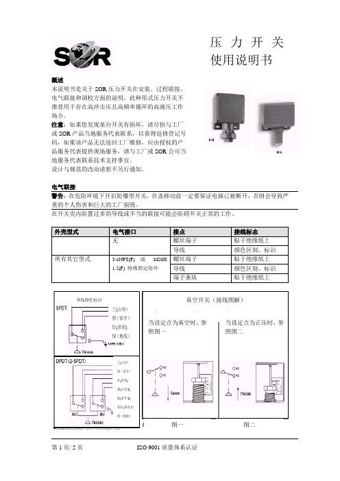
电气联接警告:在危险环境下开启防爆型开关,在盖移动前一定要保证电源已被断开,否则会导致严重的个人伤害和巨大的工厂损毁。
在开关壳内防置过多的导线或不当的联接可能会防碍开关正常的工作。
外壳型式 电气接口 接点 接线标志无螺丝端子 贴于绝缘纸上 导线颜色区别、标识 所有其它型式3/4NPT(F) 或 M20X 1.5(F) 特殊指定除外螺丝端子 贴于绝缘纸上 导线 颜色区别、标识 端子条块贴于绝缘纸上第1页/ 2页 ISO 9001质量体系认证真空开关(接线图解)当设定点为真空时,参照图一 当设定点为正压时,参照图二图一图二兰(公用) 黑(常开) 红(常闭) 绿(地线)兰(公用) 黑(常开) 红(常闭) 黄(公用2) 棕(常开2) 桔红(常闭2) 绿(地线)导线颜色标识压力开关 使用说明书安装1.用两个适当长度的1/4英寸螺栓,牢固地将开关外壳通过安装孔与仪表架或安装柱装配在一起。
2.不推荐通压力接口或电气接口的在线安装。
3.建议安装位置为电气接口竖直向下,以避免收集冷凝液,尽管如此,开关仍可全位置安装。
保证导线的电气性能符合所有应用的国家和场合,并且根据相关国家和场合的安全要求安装产品。
过程联接采用两个扳手安全地将引压管与压力接口联接:一个扳手夹住六角形压力接口,另一个扳手旋紧引压管或管接头。
重要:小心勿使压力接口松,压力接头从壳体上脱落。
警告:将外壳安装平板表面可能会导致外壳受到扭力,从而使压力开关不能正常工作。
SOR Inc. 107 差分压力开关安装说明书

These instructions provide information for installation, electrical connection, process connection and calibration of 107 Differential Pressure Switches.107Differential Pressure Switch Process pressure is sensed by a diaphragm and piston assembly. The piston responds to differential pressure and moves a shaft that actuates (deactuates) an electrical switching element. Low side pressure and a wetted adjustable range springoppose high side pressure. Calibration is accomplished by adjusting the range spring with the set point adjustment screw.Design and specifications are subject to change without notice.For latest revision, go to NOTE: If you suspect that a product is defective, contact the factory or the SOR ® Representative in your area for a returnauthorization number (RMA). This product should only be installed by trained and competent personnel.stallation, electrical connection, process Pressure Switches. ms tohat actuates ent. Low nge springs accomplished byoint adjustment screw.e, contact thea for a return uld only be107ELUse care during installation not to inadvertently move the electrical switchingelement or its housing. Movement of either could disturb the relative positions ofinternal working parts and alter calibration or render the device inoperative.The 107 Differential Pressure Switch is suited for draft range service as well as industrial air and gas services which are compatible with the wetted parts and within nameplate specifications. Contact the SOR representative in your area or the factory in Lenexa, Kansas for details.InstallationThe 107 is position sensitive. Mount the 107 so that the diaphragm is vertical (as shown above). Non-vertical mounting positions will cause calibration scale error.If condensation is expected within process piping, pressure ports should be located at 6o’clock to prevent moisture accumulation within the instrument. If condensation is not expected, the pressure ports can be positioned to any location as long as the diaphragm remains vertical.Securely mount the base plate bracket to flat surface using suitable bolts.Hazardous Locations - 107EL ❶❷❸❹❺❻❶❷❸❼❽Non-Hazardous Locations - 107ALThe high-pressure side (marked HIGH) and the low pressureside (marked LOW) have 1/8” NPT(F) process connectionsunless 1/4” NPT(F) adapters were specified.❶ Set point adjustment screw (not shown)❷ High side process connection❸ Low side process connection ❹ Hermetically sealed switching element capsule❺ 18 AWG wire leads (not shown)❻ 1/2” NPT(M) electrical conduit connection❼ 3/4” NPT(F) electrcial conduit connection❽ Weatherproof switching element housingEnsure that wiring conforms toall applicable local and nationalelectrical codes and install unit(s)according to relevant national andlocal safety codes.The SOR pressure switches have been evaluated as Type-A safety related hardware. To meet the necessary installation requirements for the SIL system, the following information must be utilized:Proof Test Interval shall be one year.Units may only be installed for use in Low Demand Mode.Products have a HFT (Hardware Fault Tolerance) of 0, and were evaluated in a1oo1 (one out of one) configuration.Form 1538 (03.12) ©2012 SOR Inc.107AL (weatherproof):Interrupt electrical power. Remove top cover plate.107EL (explosion proof): Hermetically sealed switching element capsule has18” - 18 AWG wire leads color coded and markedC - Common, NO - Normally Open, NC - Normally Closed and G - Ground (earth). (See below.)Wire Lead Color CodeSee SOR Catalog 459 for reference dimension drawings. For certified dimension drawings, contact the factory.Units in hazardous locations-prior to removal from service, make surethat the work area is declassifi ed. Failure to do so could result in severepersonal injury or substantial property damage.DPDT (2 SPDT)SPDT Blue (C) Red (NO) Black (NC)Yellow (C2)Orange (NO2)Brown (NC2)Blue (C)Red (NO)Black (NC)Green (GND)Green (GND)LO HI NO 1NO 2Differential PressureHI LO Differential PressureNormal Calibration: Turn set point adjustment screw to move spring guide plateinto alignment with desired set point on calibration scale.Precise Calibration: Device calibrated without reference to calibration scaleand low side vented.Test apparatus: ManometerVariable pressure sourceTest light or ohmmeter ❶ Connect variable pressure source to manometer and high side pressure port.❷ Connect test light or ohmmeter to C-Common and NO - Normally Open switching element contacts.❸ Raise pressure and note manometer reading when circuit closes.❹ Slowly drop pressure and note manometer reading when circuit opens.❺ Use a screwdriver to turn set point adjusting screw: counterclockwise to increase set point, or clockwise to decrease set point.❻ Repeat steps 3, 4 and 5 until contacts change at desired increasing or decreasing differential pressure set point.Do not remove other covers or attempt to adjust other parts of themechanism. All have been precisely positioned at the factory andshould not be moved in the fi eld.。
SOR压力开关,SOR液位开关
苏州迅鹏进口仪表事业部
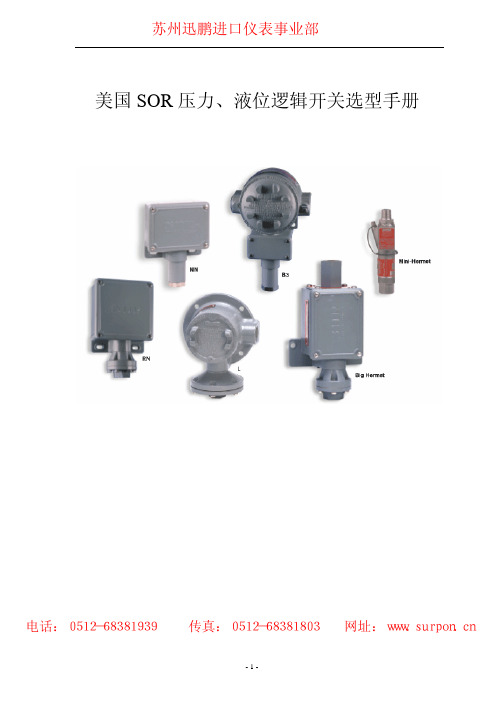
ʢࡾʣ 隔爆型: L----- 适用于 UL 认证的一级 C、D 组二级 E、F、G 组;一分区、二分区。右侧电气接口, 铸铁材质。一般不防水(选 CG 时例外),开关单元可选 1、3 组。适合于压力和真空系统。 S----- 适用于 UL 认证的一级 C、D 组;二级 E、F、G 组;一分区;三分区。上、下、左、 右侧电气接口,铸铁材质。一般不防水(选 CG 时例外),开关单元可选 1、3 组。适合于压 力和真空系统和人工复位工況。 TA----- 适用于一级 C、D 组;二级 E、F、G 组;一分区、二分区。上、下、左、右侧电气 接口,铸铁材质。一般不防水(选 CG 时例外),开关单元可选 1、3 组。适合于压力和真空 系统和人工复位工況。 LC----- 适用于 UL 认证的一级 C、D 组;二级 E、F、G 组; 一分区、二分区右侧电气接 口,不含铜的铝材结构,开关单元可选 1、2、3、4 组。带接线端子或双开关单元时,需要 较大的外壳体积。 SC----- 适用于一级 C、D 组;二级 E、F、G 组;一分区、二分区。上、下、左、右侧电气 接口,不含铜的铝材结构,开关单元可选 1、2、3、4 组。带接线端子或双开关单元时,需 要较大的外壳体积。 J4----- 防爆等级为 EExIIB-T4,采用电气连接与设定值调节分开的结构形式,铝材结构, 6 位螺丝接线端子,右侧电气 PF3/4(F)接口。开关单元可选 1、2、3、4 组。 B3----- 采用电气连接与设定值调节公开的结构形式,铝材结构,标准为 6 位卡座式接线 端子,左、右侧电气 M20*1.5 接口,CENELEC(BASEEFA)认证。如需 CSA 认证、UL 认证, 也可。开关单元可选 1、2、3、4 组。 B4----- 采用电气连接与设定值调节公开的结构形式,铝材结构,标准为 6 位卡座式接线 端子,左、右侧电气 M20*1.5 接口,CENELEC(BASEEFA)认证。开关单元可选 1、2、3、4 组。 B5----- 采用电气连接与设定值调节公开的结构形式,铝材结构,标准为 6 位卡座式接线 端子,左、右侧电气 M20*1.5 接口,CENELEC(BASEEFA)认证。开关单元可选 1、2、3、4 组。 B6----- 采用电气连接与设定值调节公开的结构形式,铝材结构,标准为 6 位卡座式接线 端子,左、右侧电气 M20*1.5 接口,CENELEC(BASEEFA)认证。如需 CSA 认证、UL 认证, 也可。开关单元可选 1、2、3、4 组。 开关单元与外壳的组合分类: 第 1 组: A、AA、B、BB、BT、BD、C、E、EE、G、K、KA、J、JJ、L、N、S、W、Y 第 2 组: GG、KK、LL、YY 第 3 组: T 第 4 组: H 第 7 组: D、M
SOR 中文操作手册
压力开关使用说明书
概述
本说明书是关于SOR压力开关在安装、过程联接、电气联接和调校方面的说明,此种形式压力开关不推荐用于存在高冲击压且高频率循环的高液压工作场合。
注意:如果您发现某台开关有损坏,请尽快与工厂或SOR产品当地服务代表联系,以获得返修登记号码,如果该产品无法返回工厂维修,应由授权的产品服务代表提供现场服务,请与工厂或SOR公司当地服务代表联系技术支持事宜。
设计与规范的改动请恕不另行通知。
电气联接
警告:在危险环境下开启防爆型开关,在盖移动前一定要保证电源已被断开,否则会导致严重的个人伤害和巨大的工厂损毁。
在开关壳内防置过多的导线或不当的联接可能会防碍开关正常的工作。
真空开关(接线图解)
当设定点为真空时,参
照图一当设定点为正压时,参照图二
兰(公用)黑(常开)红(常闭) 黄(公用2) 棕(常开2) 桔红(常闭2)绿(地线)
图一
第1页/ 2页 ISO 9001质量体系认证
图二。
压力开关设置方法

压力开关设置方法压力开关是一种用于控制和保护压力设备的电气开关设备,广泛应用于空压机、泵浦、供水设备、制冷和空调设备等工业和家用设备中。
通过对压力开关进行设置,可以实现设备的安全工作和自动控制。
下面将详细介绍压力开关的设置方法。
一、压力开关的工作原理压力开关主要由调节弹簧、压力调节螺母和开关机构组成。
当被控制的设备运行时,设备内部产生压力,当压力达到预设值时,压力作用在压力开关的调节弹簧上,使其产生形变。
当形变超过设定值时,调节弹簧会推动开关机构,从而实现开关的闭合或断开。
这样就能够控制设备的运行状态。
二、压力开关的设置步骤1. 确定设备的工作压力范围:在设置压力开关之前,首先需要了解设备的工作压力范围。
可以通过设备的工作手册或技术规格表来了解设备的额定工作压力和最大工作压力。
2. 选择合适的压力开关型号:根据设备的工作压力范围选择合适的压力开关型号。
一般来说,压力开关的额定工作压力应该大于设备的最大工作压力,以保证设备正常运行。
3. 调节开关压力:将压力开关安装在设备上,通过调节压力调节螺母将开关的压力调节到设备所需的工作压力。
调节时可以使用专用的调节工具,逐渐调节螺母,直到达到所需的工作压力。
4. 调节压力差:压力差是指压力开关在开启和关闭状态之间的压力差值。
通过调节压力调节螺母,可以调节压力开关的压力差。
一般情况下,设备需要在达到最小工作压力和最大工作压力之间切换,此时需要调节压力差。
5. 检查压力开关的工作状态:设置完成后,需要对压力开关进行检查,确保其能够正常工作。
可以通过手动加压或减压来观察开关的闭合和断开状态,并在调整过程中进行必要的调整。
6. 定期检查和维护:一旦完成设置,就需要定期检查和维护压力开关。
这包括清洁压力开关的外部和内部,检查调节弹簧和开关机构的正常运行,以及根据设备的使用情况进行必要的调整。
三、注意事项1. 安全操作:在设置压力开关时,必须注意安全操作,关闭设备电源,并使用绝缘手套和工具进行操作,以避免电击和其他安全事故的发生。
数显压力开关使用说明书
数显压力开关使用说明书
数显压力开关是一种用于测量流体压力的装置,具有数字显示功能。
下面是数显压力开关的使用说明书:
1. 安装:首先确认数显压力开关与管道连接正确,并且保证连接处密封良好。
检查电源电压是否与数显压力开关的额定电压一致,然后将电源线连接到电源插座。
2. 设置参数:打开数显压力开关的电源开关,屏幕会显示出当前的压力数值。
根据需要,可以通过按压开关或旋转控制钮来调节上下限值。
根据使用环境的要求,还可以设置报警功能等。
3. 使用:将被测流体接入到数显压力开关的压力接口,并打开流体供给。
当流体压力超过或低于设定的上下限值时,数显压力开关会发出报警信号,同时在屏幕上显示相应的警告信息。
4. 保养与维护:定期检查数显压力开关的连线是否松动,并保持清洁。
如发现任何故障或异常,应立即停止使用并联系售后服务部门。
5. 注意事项:在使用数显压力开关时,应确保其工作环境的温度、湿度等参数符合要求。
避免数显压力开关接触到强磁场或有腐蚀性的介质。
避免过大的冲击力或振动。
以上是数显压力开关的使用说明书,遵循以上步骤正确操作,能够正确并有效地使用该设备。
在使用过程中如有任何疑问或问题,请咨询厂商或售后服务部门。
SOR压力开关
Application Information
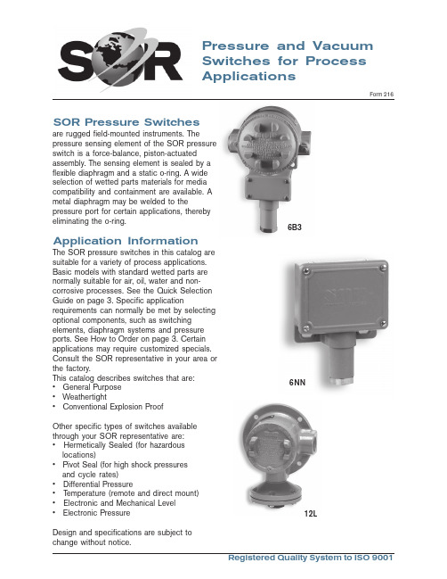
The SOR pressure switches in this catalog are suitable for a variety of process applications. Basic models with standard wetted parts are normally suitable for air, oil, water and noncorrosive processes. See the Quick Selection Guide on page 3. Specific application requirements can normally be met by selecting optional components, such as switching elements, diaphragm systems and pressure ports. See How to Order on page 3. Certain applications may require customized specials. Consult the SOR representative in your area or the factory. This catalog describes switches that are: • General Purpose • Weathertight • Conventional Explosion Proof
SOR液位开关使用说明书

SOR液位开关使用说明书SOR液位开关使用说明书工作原理上升的液面将浮球或弹簧提升式沉筒浮起,带动磁力短管上升至磁场区,吸引并触发电路或气路开关(发出液位到达信号)。
液面下降时,次序相反,电路或气路开关被释开(发出液位下降信号)。
磁力滑块(通过密封套筒)将永久磁铁和开关组件与过程液面隔离,避免磁铁腐蚀和磁力碎屑堆积。
磁力运动传输消除了由机械装置弯曲运动传输带来的疲劳,损坏及过早失效等问题。
磁力运动传输避免了因探杆型传感器引起的表面涂层问题。
在没有工厂允许的情况下,不要改变开关的原件和结构。
沉筒式结构SOR液位开关使用说明书沉筒悬挂在弹簧平衡联动杆上,液面上升时,沉筒的有效重量因受浮力而减小,弹簧回缩拉起连杆,使磁力短管在密封套筒中上升。
磁力短管的向上运动是在外部永久磁铁产生的磁场内,磁力把外部磁铁吸向磁力短管,牢固地吸附在密封套筒上,此时,微动开关被触发。
最新的信息可以登陆查询通过ISO9001认证液面下降时各次序相反,磁力短管下落至磁场外,复位弹簧将外部磁铁拽离密封套管,微动开关复位。
浮球式结构引压口联接外浮筒接管应当平直且不受干扰,控制头与外浮筒垂直中心线在3℃内。
注意:顶装式控制头与容器法兰或短管安装成与容器的垂直或水平中心线不超过3℃。
(即:外浮筒式与顶装式均应垂直安装)接管长度应控制在最小,以使开关整体更稳定。
如有需要,应采用接管悬挂或支承装置。
控制机构在液体中动作,接管中很可能堆积沉淀物,应采用“T”形或“+”形管接头,允许定期清洗接管。
排污阀及吹扫阀可用于清洁外浮筒和接管。
正常运行中,所有接管上阀门应完全打开,因为限流可能导致误动作。
警告:介质温度超过232℃时,不推荐在外浮筒上使用保温材料。
电气接线警告:在开启开关外壳之前,一定要保证电源已经被断开。
忘记断开电源可能会导致严重个人伤害或巨大的财产损毁。
请确认接线以及接线的联接符合所有当地和国际电气规范。
外壳上的电气接口可旋转360°,只需松开外壳底座的定位螺钉即可。
双设定压力开关中文说明书

注意:超程距离已在出厂前预先设定,也就是说,为了达到最佳的性能,开关元件组合已精确地在外壳内定 位。通常在现场不必再行调节。如果有必要进行调节,则必须严格地遵循制造厂批准的步骤。任何在现场随
便的移动或更换可能会降低性能、使担保作废并可能使该装置失效。
校准
a. 拆除外壳的盖子。 b. 若要提高1号(左侧)开关元件起动时的设定值,则用3/4英寸开口扳手以顺时针方向转动六角调节螺母。 c. 调节时越过调节螺母的顶部观察外壳内壁上的校准刻度,即可达到近似的设定值。可用一1/4% 的外接压力
其压力传感元件是一对力平衡式、活塞驱动的组合 件,通过弹性膜片和静态密封O形环予以密封。此结 构中唯有压力接口、两套膜片和O形环传感组合件是 接触介质的部件。
重要:务必拧紧和固定该工艺接头,使压力开关上所 承受的任何弯曲和扭曲力量均减小到最低限度。切勿 将压力接口从本体上松开, 因为这可能会造成泄漏或
安装
185.7 * 7.31
70.4 * 2.77
高低压双点系列压力开关可用适当的螺栓固定在隔 墙、仪表盘或管架支柱上。当在不规则或不平整表面 上安装压力开关时,先要在外壳和安装面之间的螺栓 上套上橡胶垫圈。
单位= mm
in.
注意:若不在外壳和安装面之间放置橡胶垫圈,就可 能在外壳上产生扭力,从而导致开关的假动作,或使 该开关失效。
不推荐采用光依靠工艺接口或电气接口的安装方式。
*
251.2 9.89
9.7 .38
直径为9/32 的固定孔
57.2 (通常2个)
114.3 2.25 4.50
工艺接头
V1 全天候密封型
138.9 5.47 69.6
2.74
电气接头
3/4 NPT(F) (制造厂密封
索尔SOR压力传感器选型资料(中文版)

聆听机械微米级专业的判断一个帕斯卡的反应,我们也会告诉您我们一直在努力追求微帕自控的力量SOR索尔压力开关SOR公司(中文名称索尔公司)成立于1946年,是世界上唯一一家集生产各类机械及电子压力、差压、温度、流量、液位开关及变送器于一体的专业化国际公司,总部位于美国肯萨斯州州府,现有员工300人,其压力开关类产品产量位居世界第一。
压力开关产品主要采用静态O型圈密封的活塞-弹簧-膜片组合式结构,具有抗震、抗过压能力强,测量范围广且回差小、使用寿命长等特点。
其生产的高静压低差压开关是世界上独一无二的。
其核级压力及差压开关是世界上不多的取得IEEE认证的产品。
SOR的机械液位开关全部满足ANSIB31.1和B31.3国际电力和石化行业压力容器标准,包括机械式浮球及沉筒两类,其独特的分级冷凝球降温措施能够很好地保证液位开关的开关单元部分免受高温蒸汽的影响,可以可靠地应用于高温工况,越来越受到客户的青睐。
除机械类产品外,SOR的电子产品种类也是非常丰富的,包括热差式流量开关、非接触式超声波变送器、接触式超声波开关,射频导纳开关及变送器、以及集开关、变送器、实时显示三位一体的SGT,该仪表不仅有实时压力显示、独立的开关量输出,而且有4~20毫安模拟量输出。
非接触式超声波变送器具有高能量、低频率、自动增益调节三大特点使其能够应用于诸如碳黑、干灰、啤酒、石膏等高粉尘、高泡沫及高雾气的复杂环境中,帮助很多用户解决了多年来用其他超声波产品甚至是雷达产品都解决不了的难题。
压力控制器(压力计)NN²最大工作压力30 inHg 到 7000 psig ²0.25mm活塞行程,使用寿命长²设定点可调²10amps@250VAC²CSA, CE²NEMA 4, 4X, IP65RN ²最大工作压力30 inHg 到 7000 psig ²0.25mm活塞行程,使用寿命长²设定点可调²10amps@250VAC>²CSA, CE NEMA 4, 4X, IP65L ²最大工作压力30 inHg 到 7000 psig²0.25mm活塞行程,使用寿命长²设定点可调²10amps@250VAC²CSA, CE UL: Class I, Group C, Div. 1B3²最大工作压力30 inHg 到 7000 psig²0.25mm活塞行程,使用寿命长²设定点可调²10amps@250VAC²CSA, CE UL/CSA: Class I, Group B, Div. 1; ATEX: Eex d IIC T6V1²双设定点²最大工作压力30 inHg 到 4000 psig ²0.25mm活塞行程,使用寿命长²设定点可调²10amps@250VAC CSA, CEV2²双设定点²最大工作压力30 inHg 到 4000 psig²0.25mm活塞行程,使用寿命长²设定点可调²10amps@250VAC UL/CSA: Class I, Group A, Div. 1; SnapSw: UL/CSA, ATEX, SAA差压控制器(差压计)101NN,121NN ²最高工作压力从 3 到500 psig²设定点可调²可适用于系统静压突变的工况²15amps@250VAC²CSA, CE ²NEMA 4, 4X, IP65101RN,121RN ²最高工作压力从 3 到500 psig²设定点可调²系统最大静压为1000 psig²可适用于系统静压突变的工况²15amps@250VAC²CSA, CE²NEMA 4, 4X, IP65101L,121L ²最高工作压力从 3 到500 psig²设定点可调²系统最大静压为1000 psig²可适用于系统静压突变的工况²15amps@250VAC²CSA, CE²UL: Class I, Group C, Div. 1101B3,121B3²最高工作压力从 3 到500 psig²设定点可调²系统最大静压为1000 psig²可适用于系统静压突变的工况²15amps@250VAC²CSA, CE²UL/CSA: Class I, Group B, Div. 1; ATEX: Eex d IIC T6101AG,121AG ²最高工作压力从 3 到500 psig²设定点可调²系统最大静压为1000 psig²可适用于系统静压突变的工况²15amps@250VAC²CSA, CE ²UL/CSA: Class I, Group A, Div. 1; ATEX: Eex d IIC; SnapSw:UL/CSA, ATEX, SAARB²最高工作压力从 0.5 到1000 psig²设定点可调 r²可适用于系统静压突变的工况²CSA, CES ²最高工作压力从 0.5 到500 psig²设定点可调²可适用于系统静压突变的工况²UL: Class I, Group C, Div. 1102W1,103W1²设定点可调²最高工作压力从 7 inwc 到2500 psig²系统最大静压为3000 psig²不锈钢外壳²CSA, CE|液位控制器(液位计)100 系列,741-743,801,802²高温环境,温度从 -65°F 到 1000°F²最大工作压力为128bar²控制器单元为不锈钢或者高温陶瓷,抗高温、抗腐蚀²干净/含有杂质液体²最小额定电流为3A@ 220VAC²全系列为ANSI/ASME 标准²所有材质通过ASTM 等级的材料认证 ²UL, CSA, ATEX, SAA ²带腔体侧装200 系列,740-803²高温环境,温度从 -65°F 到 1000°F²最大工作压力为690bar²控制器单元为不锈钢或者高温陶瓷,抗高温、抗腐蚀²干净/含有杂质液体²最小额定电流为3A@ 220VAC²全系列为ANSI/ASME 标准 ²所有材质通过ASTM 等级的材料认证²UL, CSA, ATEX, SAA²带腔体侧装700 系列,730-750²高温环境,温度从 -65°F 到 1000°F²最大工作压力为128bar²控制器单元为不锈钢或者高温陶瓷,抗高温、抗腐蚀²干净/含有杂质液体²全系列为ANSI/ASME 标准²所有材质通过ASTM 等级的材料认证²UL, CSA, ATEX, SAA 顶装300系列²高温环境,温度从 -65°F 到 1000°F²最大工作压力为128bar²控制器单元为不锈钢或者高温陶瓷,抗高温、抗腐蚀²干净/含有杂质液体²全系列为ANSI/ASME 标准²所有材质通过ASTM 等级的材料认证²UL, CSA, ATEX, SAA 顶装108, 208 系列²高温环境,温度从 -65°F 到 1000°F²最大工作压力为690bar²控制器单元为不锈钢或者高温陶瓷,抗高温、抗腐蚀²干净/含有杂质液体²最小额定电流为3A@ 220VAC²全系列为ANSI/ASME 标准 ²所有材质通过ASTM 等级的材料认证²UL, CSA, ATEX, SAA 带腔体侧装1500 系列,1710²最大工作压力为1500 psi, 温度从 -40°F 到 400°F²所有材质通过ASTM 等级的材料认证²CSA温度控制器(温度计)NN ²工作温度从 -50° 到 1000° F²设定点可调²整体安装或分体安装²可选316SS 材质保护套管²316SS 材质探头 ²CSA, CERN²工作温度从-50° 到 1000° F²设定点可调²整体安装或分体安装²316SS 材质保护套管连接²316SS 材质探头 ²CSA, CEL ²工作温度从 -50° 到 1000° F²设定点可调²整体安装或分体安装²316SS 材质保护套管连接²316SS 材质探头 ²UL: Class I, Group C, Div. 1B3²工作温度从 -50° 到 1000° F²设定点可调²整体安装或分体安装²316SS 材质保护套管连接²316SS 材质探头 ²UL/CSA: Class I, Group B, Div. 1; ATEX: EEx d IIC射频导纳651单点RF 控制器²可用作报警器或指示器²不受探头上的工艺物料挂料的影响²经济性好的单点式检测仪表²可用于12VDC 供电²经FM (工厂互助保险公司)认证,并经CSA (加拿大标准协会)认证和CENELEC (欧洲电工技术标准化委员会)认证可应用于危险性工作地点²可在现场选择的故障自动保护功能²环境温度范围-40~71℃²重复精度0.5%²外壳防护等级NEMA 4X 和IP65681单点RF 控制器(具备自检功能)²提供单点控制器功能²通过连续性的自我测试(自检)对开关的运行进行检查。
SOR压力开关(中文)
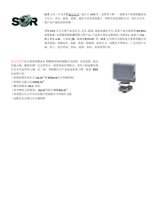
压力开关产品主要采用静态O型圈密封的活塞膜片式结构,具有抗震、抗过压能力强,测量范围广泛且回差小,使用寿命长等特点。
其生产的高静压低压差开关是世界上独一无二的。
其核极压力产品也是世界上唯一取得IEEE 认证的产品。
·控制范围从负压力1kg/cm2到680kg/cm2,分多级控制;
·控制压力最大为680kg/cm2
·微压控制为15mm水柱
·真空-0-压力控制为:1kg/cm2(负压)-0-5.5kg/cm2
·双设置点压力开关可以独立控制两点不同的压力值
·切换差分可调与不可调两种
SOR公司(中文名称索尔公司)成立于1946年,是世界上唯一一家集生产各类机械及电子压力、差压、温度、流量、液位开关及变送器于一体的专业化国际公司,其压力开关类产品产量位居世界第一.
美国SOR公司主要产品为压力、差压、温度、流量及液位开关,所有产品全部采用ISO9001质量标准,分普通型和防爆型两大类产品,产品的主要认证机构有:美国UL、加拿大CSA、澳大利亚ASS、日本的JIS、欧洲CENELEC等。
SOR公司的开关量仪表主要采用膜片活塞式结构,有耐高压、高温、防震、防腐蚀、抗冲击力、切换差小等特点、广泛应用于石油、化工、电力冶金、药品、造纸、食品、水处理等行业.。
sor压力开关检修规程

sor压⼒开关检修规程SOR压⼒开关检修规程⽬录1.0⽬的 (2)2.0范围 (2)3.0参考 (2)4.0HSE (2)5.0定义 (2)6.0责任 (3)7.0规程步骤 (3)7.1压⼒开关主要性能指标: (3)7.2压⼒开关的校验: (3)7.2.1严格执⾏本规程4.0HSE (3)7.2.2检定条件 (3)7.2.3校验项⽬ (4)7.2.4进⾏正确的填写校验单 (5)7.2.5记录保存 (5)7.3压⼒开关的使⽤和维护 (5)1.0⽬的制定本规程的⽬的在于为本规程的最终⽤户提供明确的内容和步骤,确保仪表维护检修⼈员在执⾏任务时能够在没有监督或很少监督的情况下,按照赛科规定的标准,以安全有效可靠的⽅式履⾏⾃⾝的职责。
2.0范围本规程适⽤于:SOR压⼒开关型号:6RN-EG3-M4-C2A-HB3.0参考本规程参考了以下⽂件:中华⼈民共和国航空航天⼯业部航空⼯业标准压⼒开关通⽤规范HB6680-92SOR压⼒开关说明书4.0HSE在执⾏规程时,你若确认出未知的HSE风险,向你的直接主管进⾏汇报。
为了确保检修⼈员以及仪表设备本体的安全,在执⾏相关操作之前必须了解和参考以下的安全提⽰:1.建议在⼯作和环境条件许可的情况下选择在仪表校验室执⾏。
2.必须严格检查检修仪表(压⼒开关)的状况。
3.严格检查检修仪表(压⼒开关)的清洁度,不准仪表本体或内部带⼯艺介质,以免造成检修⼈员和标准仪器的伤害。
4.禁⽌在爆炸性环境中打开处于带电⼯作状态的压⼒开关接线盖。
5.严格检查供电电源的安全状况,防⽌漏电事故发⽣。
6.严格检查⼯作环境状况,以免发⽣⼈员伤害事故发⽣。
7.检修⼈员必须在⾝体健康状况允许的情况下执⾏本规程。
5.0定义压⼒开关:通过压⼒变化驱动触点的开关耐压压⼒:能够承受⽽不引起零件破裂,泄漏,永久变形和功能失效以及其他损坏的最⼤压⼒驱动点:压⼒开关的触点从初始状态切换到相反状态时的压⼒回动点:压⼒开关的触点从驱动状态返回到初始状态时的压⼒死区:驱动点和回动点之间的压⼒差⼯作循环:压⼒从零(绝对压⼒或表压)升⾄需要的系统正常压⼒,然后从系统正常压⼒降⾄零的过程称为⼯作循环。
SOR开关说明书

∙SOR液位开关使用说明书∙SOR液位开关使用说明书SOR液位开关基本原理上升的液面将浮球或弹簧提升式沉筒浮起,带动磁力短管上升至磁场区,吸引并触发电路或气路开关(发出液位到达信号)。
液面下降时,次序相反,电路或气路开关被释开(发出液位下降信号)。
磁力滑块(通过密封套筒)将永久磁铁和开关组件与过程液面隔离,避免磁铁腐蚀和磁力碎屑堆积。
磁力运动传输消除了由机械装置弯曲运动传输带来的疲劳,损坏及过早失效等问题。
磁力运动传输避免了因探杆型传感器引起的表面涂层问题。
在没有工厂允许的情况下,不要改变开关的原件和结构。
SOR液位开关沉筒式结构沉筒悬挂在弹簧平衡联动杆上,液面上升时,沉筒的有效重量因受浮力而减小,弹簧回缩拉起连杆,使磁力短管在密封套筒中上升。
磁力短管的向上运动是在外部永久磁铁产生的磁场内,磁力把外部磁铁吸向磁力短管,牢固地吸附在密封套筒上,此时,微动开关被触发。
液面下降时各次序相反,磁力短管下落至磁场外,复位弹簧将外部磁铁拽离密封套管,微动开关复位。
SOR液位开关浮球式结构浮球与一根机械连杆固定在一起,液面上升至浮球,浮力使连杆上升,磁力短管升入密封套筒中,磁力短管的向上运动是在外部永久磁铁产生的磁场内。
磁力把外部磁铁吸向磁力短管,牢固地吸附在密封套管上,此时,微动开关被触发。
液面下降时各次序相反。
磁力短管下落至磁场外,复位弹簧将外部磁铁拽离密封套筒,微动开关复位。
SOR液位开关引压口联接外浮筒接管应当平直且不受干扰,控制头与外浮筒垂直中心线在3℃内。
注意:顶装式控制头与容器法兰或短管安装成与容器的垂直或水平中心线不超过3℃。
(即:外浮筒式与顶装式均应垂直安装)接管长度应控制在最小,以使开关整体更稳定。
如有需要,应采用接管悬挂或支承装置。
控制机构在液体中动作,接管中很可能堆积沉淀物,应采用“T”形或“+”形管接头,允许定期清洗接管。
排污阀及吹扫阀可用于清洁外浮筒和接管。
正常运行中,所有接管上阀门应完全打开,因为限流可能导致误动作。
压力开关操作说明书

目录1 说明§1.1 重要说明§1.2 开关标识2 探测头安装§2.1 压力与真空探测头§2.2 差压探测头§2.3 温度探测头3 封装外壳的安装§3.1 “C”型外壳§3.2 “Z”型外壳§3.3 “V”型和“W”型外壳§3.4 “M”型外壳4 电气安装5 设定点调节6欧共体标准符合说明1 说明§1.1 重要说明* BETA压力开关属于精密仪器请正确放置或搬动。
BETA压力开关在达到设定点的(差压)压力或者温度时开关动作。
* 在按照说明书指示正确安装,该开关的设计与结构是完全免维护的。
切莫采用液态油或油脂润滑开关的任何部件。
* 除了更换外壳密封与安装支架外,不要移动或更换本开关的任何部件。
* 避免暴露在超高温、超低温、有侵蚀性环境中,-30~80℃为适宜温度。
* 调节螺丝有自锁性,所以在调节设定点后禁止封死调节螺丝。
* 安装前请详细检查铭牌上数据。
* 所有尺寸均以mm毫米标注。
* 如果您需要帮助请与供应商联系,开关只有在去污清洗后才能进行维护检修。
* 如果您需要额外的膜片O形圈和微动开关,请给出序列号向供应商购买。
* 开关的检修维护请由专业的仪表工程师实施。
除了更换膜片O形圈和微动开关以外,其它形式的检修维护有厂方执行。
* 非厂方检修维护的操作会影响产品本身的质量保证。
* 本章节的指导说明书的步骤也是安装步骤说明。
* 地基与工程环境的强烈振动可能会影响开关的正常功能。
压力开关的铭牌上面标明了规格型号,4到7步可以确定该压力开关的设计组成,后缀的X+数字来表明特殊要求,该特殊要求可参照数据书。
外壳封装C1-P304L-S1N-B1-K1-Y-X2第一个字符即第一步标明了外壳封装形式:C、V、W、Z或M,参照图1-4和15。
探测头C1-P304L-S1N-B1-K1-Y-X2第一个和最后一个字符构成第二步标明了探测头规格及功能,参照图5-12和表1。
SOR Inc. 101 121 差分压力开关说明书
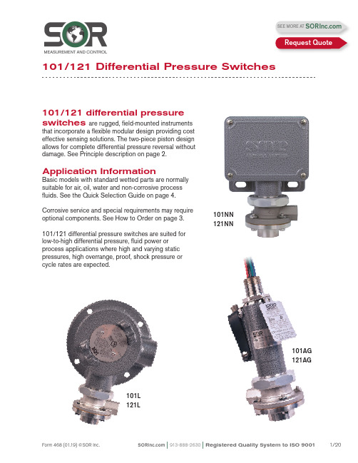
101/121 differential pressure switches are rugged, field-mounted instrumentsthat incorporate a flexible modular design providing cost effective sensing solutions. The two-piece piston design allows for complete differential pressure reversal without damage. See Principle description on page 2.Application InformationBasic models with standard wetted parts are normally suitable for air, oil, water and non-corrosive process fluids. See the Quick Selection Guide on page 4.Corrosive service and special requirements may require optional components. See How to Order on page 3.101/121 differential pressure switches are suited for low-to-high differential pressure, fluid power or process applications where high and varying static pressures, high overrange, proof, shock pressure or cycle rates are expected.101NN 121NN101AG 121AG101L 121L101/121 Differential Pressure SwitchesSEE MORE AT Request QuoteF h = Force, Hi Pressure F l = Force, Lo PressureF s = Force, Range SpringF d = Force, Resultant DifferentialF d = F h - (F l + F s )Process pressure is sensed by a diaphragm-piston combination. Hi-side system pressure acts on the piston to product force F h . It is counteracted by the adjustable range spring force F s and Lo-side system pressure acting on the backside of the piston to produce force F l . The resultant force F d acts on the piston and overcomes the force of the adjustable range spring [F d = F h – (F l + F s )] and moves a shaft that actuates (deactuates) an electrical switching element.AF hF lF sF dNCNOCDifferential Pressure SwitchPrincipleQuick Selection GuideBasic Series 101/121 differential pressure switches with standard wetted parts are normallysuitable for air, oil, water and non-corrosive processes. Refer to the Quick Selection Guide section on page 4. Corrosive service and particular customer requirements may require optionalcomponents. Refer to the How to Order section on this page or the dedicated page to locate optional components, such as: housings, switching elements, diaphragm systems, pressure ports and accessories. Each position in the model number, except Accessories, must have a designator.101NN-K3-N4-C1A-YYModel Number SystemSeriesHousingDiaphragm& O-RingSwitching Element Adjustable RangePressure PortAccessoriesApplicationsThe Series 101/121 differential pressure switches in this catalog are suitable for a wide variety of process and fluid power applications. Specific application requirements can normally be met by selecting optional components, such as, switching elements and diaphragm systems. Certain applications may require customized specials. Consult local representative or the factory.Weathertight, conventional explosion proof and hermetically sealed explosion proof models are presented in this catalog.How to OrderSteps 1 through 5 are required; Step 6 is optional. Orders must have complete model numbers, i.e. each component must have a designator.Order information must include:a) Set Point (increasing or decreasing)b) If decreasing Set Point, state from what greater Set Point is approached c) Normal system (static) pressureStep 1: Select Housing for type of service (pages 5 & 6).Step 2: Select electrical Switching Element for housing and electrical service (pages 6 & 7).Step 3: Select Adjustable Range according to Set Point (page 8).Step 4:Select Diaphragm and O-Ring for process compatibility and containment (page 9).Step 5:Select Pressure Port for process connection (page 9). Step 6: Select Accessories as required for service (page 10).If Agency Listed, Certified or Approved differential pressure switches are required, see page 11 for components that must be specified.Differential Pressure SwitchHow to OrderDifferential Pressure Switch Principle Specify model number from table below.WeathertightNEMA 4, 4X, IP65Hazardous LocationsClass I, Groups C & D;Class II, Groups E, F & G;Divisions 1 & 2Hazardous LocationsClass II, GroupsE, F & G; Divisions 1 & 2See Agency Listings page 11.See Switching Element Groups 1, 2, 3, 4 page 6.See Agency Listings page 11.See Switching Element Groups 1, 2, 3, 4 page 6.Contains UL Listed, CSA Certified, ATEX and SAA Approved Electrical: 1/2” NPT(M)-Top Material: See Switching Element Group 5 page 6.See Switching Element Groups 1, 2, 3, 4 page 6.See Agency Listings page 11.See Switching Element Groups 1, 2, 3, 4 page 6.Open bracket with exposed switchingelement does not meet NEMA 1.See Switching Element Groups 1 & 3 page 6.See Agency Listings page 11.See Switching Element Group 7 page 6.Weathertight —NEMA 4, 4X, IP65Electrical: 3/4” NPT(F)- Right Material: AluminumCover: heavy duty with Viton gasketN4See Agency Listings page 11.See Switching Element Groups 1, 2, 3, 4 page 6.See Switching Element Groups 1 & 3 page 6.RN RM Electrical-RT: 3/4” NPT(F)-Right Electrical-RS: M20 x 1.5-Right Six-place compression type terminal block Material: 316SSRT RSContains UL Listed, CSA Certified and SAA Approved hermetically sealed switching elements. Electrical: 3/4” NPT(F)-TopMaterial: Copper-free** aluminumWeathertight: NEMA 4/4XSee Switching Element Group 6 page 6.Class II, Groups E, F & G; Divisions 1 101NN -K3-N4-C1A-YYSeparate electrical and set point adjustment compartments. WeathertightSix-place compression type terminal blockSee Agency Listings page 11.Class II, Groups E, F & G; Divisions 1 & 2 as an outlet box only.Electrical: 3/4” NPT(F)-Left, Right, TopSix-place compression type terminal block with Optional LL Material: Copper-free** aluminum Class I, Groups A, B, C, D; Class II,See Switching Element Groups 1 & 3 page 6.*B3* Not recommended for direct mount where vibration is expected. Housing should be securely mounted to a flat surface (bulkhead or panel rack) or pipe stanchion. ** Consult the factory.See Switching Element Groups 1 & 3 page 6.See Switching Element Groups 1, 2, 3, 4 page 6.See Switching Element Groups 1 , 3, 7 page 6.See Switching Element Groups 1, 2, 3, 4, 7 page 6.Hazardous Locations — Conventional Explosion ProofATEX and SAA Approved Electrical: 1/2” NPT(M)-TopMaterial: See Switching Element Group 5 page 6.101NN-K3-N4-C1A-YYCross reference compatibility chart above to ensure that switching element will fit in housing.Notes1. AC/DC electrical ratings for switchingelements K, KK, KA, J, JJ, G, GG, A, AA, L, LL, E, EE, C, S, B, BB, Y, YY, W, T, H, D and M are UL Recognized and CSA Certifiedwith conditions and exceptions specified in Note 3.2. The hermetically sealed switching elementcapsule is UL Listed, CSA Certified, ATEXand TestSafe Approved as a snap switch in accordance with the following table withconditions and exceptions specified inNote 3.3. DC electrical ratings are for resistive loadsonly. DC ratings marked with an asterisk (*) are not agency recognized or certified buthave been verified by testing or experience.Switching Element101NN-K3-N4-C1A-YY 4. DPDT switching elements have wire leadsexcept when supplied in housings RN, RT,RM, RS, RB, B3, B4, B5, B6.5. Switching element minimum/maximumambient temperatures:-40 to 167o F (-40 to 75o C) AF, AG, EB,EF, EG, JB,JF, JG, JR, KB -65 to 400o F (-54 to 204o C) B, Y, W-65 to 250o F (-54 to 120o C) A, E, J-65 to 180o F (-54 to 80o C) All others 6. Dead band multipliers must be applied to thetypical dead band figures given in thespecification tables on page 8.7. Switching elements B, W and Y have anElgiloy spring. Experience indicates goodservice in atmospheres with corrosivegases - H2S, ammonia, etc.CAUTION: The switching element assembly has been precisely positioned in the housing at the factory for optimum performance. Any inadver-tent movement or replacement in the field will degrade performance, could render the device inoperative and may void the warranty unless factory authorized procedures are followed.Differential Pressure SwitchAdjustable Range101NN-K 3-N4-C1A-YYThis table lists designators for corresponding adjustable ranges, dead bands, maximum system pressure and maximum differential pressure. Adjustable range is expressed for increasing pressure: the Set Point must be within the adjustable range. Dead band is expressed as typical at mid-range. See dead band considerations at the bottom of this page.Notes1. Ambient temperature range: -30 to 180o F (-34 to 80o C). Check restrictions, page 7, for optional electrical switching elements and page 9 for optional diaphragm systems.2. Metric bar (mbar) values are practical equivalents of the mathematical conversions. This data appears on the product nameplate when metric engineering units are specified.3. CAUTION: When the process could be considered dirty in terms of suspended particles, it is recommended that 20-micron in-line filters be installed on the Hi and Lo pressure ports.4. To achieve optimum performance, the 101/121 should be calibrated under simulated system operating conditions.Dead Band Considerations1. Dead band values are expressed as typical expected at mid-adjustable range and 50% maximum system pressure (static pressure) using the standard K switching element.2. Dead bands are fixed (non-adjustable), except when T or H switching elements are used.3. A dead band multiplier must be applied to the typical dead band value shown in adjustable range above whenever an optional switching element is specified.4. Dead band can be widened by selecting an optional switching element with a multiplier greater than 1.0.5. Use of metal diaphragms may have additional impact on Dead band values. Contact thefactory for details.Differential Pressure SwitchExample: Model 101NN-G3-N4-C1ATypical Dead Band 0.7 psid G-Switching Element muliplier 2 Corrected Typical Dead Band0.7 x 2 = 1.4 psidDiaphragm & O-Ring101NN-K3-N4-C1A-YY Notes1. N4 diaphragm system is standard. It isnormally suitable for air, oil, water andnon-corrosive processes.2. Other diaphragm and o-ring combinationsmay be available. Consult the factory or the SOR representative in your area for more information.3. Wetted parts have been selected asrepresenting the most suitable commercially available material for use in the serviceintended. However, they do not constitute a guarantee against corrosion or permeation, since processes vary from plant to plant and concentration of harmful fluids, gases orsolids vary from time to time in a givenprocess. Empirical experience by usersshould be the final guide. Alternate materials based on this are generally available.4. Differential pressures exceeding 100 psidmay affect Set Point when M2, M4, or H4diaphragm and o-ring combination is used. 5. Dead bands are higher when using metaldiaphragm options. Consult the factory.6. This table shows allowable minimum andmaximum temperatures for o-rings.Step 5: Pressure Port101NN-K3-N4-C1A-YYNotes1. C1A pressure port is standard. It is normallysuitable for air, oil, water and non-corrosive processes.2. Other pressure port materials and connectionsizes may be available. Consult the factory or the SOR representative in your area for more information.Material & SystemsDifferential Pressure SwitchStep 6: Accessories101NN-K3-N4-C1A-YY101/121Differential Pressure SwitchAgency ListingsULCSAATEX/ IECEx orINMETRODifferential Pressure SwitchManual Reset101RB -D 3-N4-C1A-YYSeries 101/121 Differential Pressure Switches in this catalog may be specified with manual reset electrical switching elements D or M.D actuates automatically on increasing pressure. M actuates automatically on decreasingpressure. Depress the button, covered by the weathertight boot to manually reset. Housings must be RB weathertight or S explosion proof because of the requirement of a hub for themanual reset assembly. Refer to page 3 for order instructions.Approximate WeightsActual shipping weights may vary from the charted values because of product material,configuration and packaging requirements.RB-WeathertightS-Explosion ProofDifferential Pressure SwitchSOR recognizes that there is no industry convention with respect to terminology and definitions pertinent to pressure switches. This glossary applies to SOR Pressure Switches.Adjustable RangeThe span of pressure between upper and lower limits within which the pressure switch may be adjusted to actuate/deactuate. It is expressed for increasing differential pressure.Dead BandThe difference in pressure between the increasing Set Point and the decreasing Set Point. It is expressed as “typical,” which is an average with the increasing Set Point at mid- adjustable range for a pressure switch with the standard K switching element. It is normally fixed (nonadjustable).Differential Pressure SwitchA bi-stable electromechanical device that actuates/deactuates one or more electrical switching element(s) at a predetermined discrete differential pressure (Set Point) upon rising or falling differential pressure.DPDT Switching ElementDPDT is two synchronized SPDT switching elements that actuate together at increasing Set Point and deactuate together at decreasing Set Point. Discrete SPDT switching elements allow two independent circuits to be switched; i.e., one AC and one DC.The synchronization linkage is factory set, and is not field adjustable. Synchronization is verified by connecting test lamps to the switching elements and observing them go “On” simultaneously at actuation and “Off” simultaneously at deactuationHermetically SealedA welded steel capsule with glass-to-metal, factory-sealed, electrical leads that isolatesthe electrical switching element(s) from the environment.Maximum Differential PressureThe maximum difference in pressure that may be continuously applied between the Hi and Lo (Lo and Hi) pressure ports without causing permanent change of Set Point, leakage or material failure.OverrangeThe maximum input pressure that may be continuously applied to the pressure switch without causing permanent change of Set Point, leakage or material failure.Proof PressureThe maximum input pressure that may be continuously applied to the pressure switch without causing leakage or catastrophic material failure. Permanent change of Set Points may occur, or the device may be rendered inoperative.RepeatabilityThe ability of a pressure switch to successively operate at a Set Point that is approached from a starting point in the same direction and returns to the starting point over three consecutive cycles to establish a pressure profile. The closeness of the measured Set Point values is normally expressed as a percentage of full scale (maximum adjustable range pressure).Set PointThat discrete pressure at which the pressure switch is adjusted to actuate/deactuate on rising or falling pressure. It must fall within the adjustable range and be called out as increasing or decreasing differential pressure. SPDT Switching ElementSingle-Pole, Double Throw (SPDT) has three connections: C — Common, NO — Normally Open and NC — Normally Closed, which allows the switching element to be electrically connected to the circuit in either NO or NC state.Glossary of T ermsDifferential Pressure Switch6.40.25 MIN TO 76.23.00 MAX3/4 NPT(F)(STD)1/2 NPT(F)(OPT)7.10.281/4 NPT(F) HI SIDE1/4 NPT(F) LO SIDEDimensions in this catalog are for reference only. They may be changed without notice. Contact the factory for certified drawings for a particular model number. Dimensions are expressed as millimeters over inches (Linear = mm/in.)Housing: Weathertight - Nonhazardous Service (NEMA 4, 4X IP65)Housing: NN, N3, N4Dimensions in this catalog are for reference only. They may be changed without notice. Contact the factory for certified drawings for a particular model number. Dimensions are expressed as millimeters over inches (Linear = mm/in.)Housing: RB Manual ResetWeathertight - Non-hazardous Service (NEMA 4, 4X IP65)Drawing 00906046.40.25 MIN TO 76.23.00 MAX Dimensions in this catalog are for reference only. They may be changed without notice. Contact the factory for certified drawings for a particular model number. Dimensions are expressed as millimeters over inches (Linear = mm/in.)Housing: H3 Open BracketGeneral Purpose - Non-hazardous ServiceHousing: PP, P3 NEMA 1Drawing 0090601Dimensions in this catalog are for reference only. They may be changed without notice. Contact the factory for certified drawings for a particular model number. Dimensions are expressed as millimeters over inches (Linear = mm/in.)Housing: LHousing: LCConventional Explosion Proof - Hazardous ServiceClass I, Group C, D; Class II, Group E, F, G: Divisions 1 & 2Drawing 0090606Housing: SCDimensions in this catalog are for reference only. They may be changed without notice. Contact the factory for certified drawings for a particular model number. Dimensions are expressed as millimeters over inches (Linear = mm/in.)Conventional Explosion Proof - Hazardous ServiceClass I, Group C, D; Class II, Group E, F, G: Divisions 1 & 2Conventional Explosion Proof - Hazardous ServiceClass I, Groups C, D; Class II, Groups E, F, G: Divisions 1 & 2Housing: B3, B4, B5, B6Class I, Groups B, C, D; Class II, Groups E, F, G; Divisions 1 & 2Housing: T AClass I, Groups A, B, C, D; Class II, Groups E, F, G; Divisions 1 & 2Dimensions in this catalog are for reference only. They may be changed without notice. Contact the factory for certified drawings for a particular model number. Dimensions are expressed as millimeters over inches (Linear = mm/in.).Drawing 0090610PROCESS CONNECTION CONNECTION OPTIONALDrawing 0090611PROCESS CONNECTIONPRODUCT CERTIFICATION DRAWING ALL DIMENSIONS ARE ±1/16 IN UNLESS OTHERWISE SPECIFIEDMMLINEAR =INK MITCHELLM SMITHS BOAL14 SEP 2011DIMENSION DRAWING 101/121 BA EO NUMBER: 5095SCALE: 0.7000906125SHEET 1 OF 1BMODEL #SALES ORDER #LINE ITEM #PURCHASE ORDER #SALES PAGEPROCESS CONN SIZE LENGTH A 1/4 NPTM SHOWN 29.71.171/2 NPTF37.61.481/2 NPTM 34.81.373/4 NPTF 39.91.5741.6ADDFOR M20 X 1.5 F 1.64ELECTRICAL CONNECTION6.40.25457.218.00Hermetically Sealed Explosion Proof - Hazardous ServiceClass I, Groups A, B, C, D; Class II, Groups E, F, G; Divisions 1 & 2Housing: BAHousing: AG, AH Dimensions in this catalog are for reference only. They may be changed without notice. Contact the factory for certified drawings for a particular model number. Dimensions are expressed as millimeters over inches (Linear = mm/in.)Drawing 0090612Drawing 0091067。
Sor压力开关设定
Sor压力开关设定、调试步骤
具体内容,请参考工厂英文版操作手册,如两者内容有出入,以英文版为准。
在校验设定值时,在常压压状态下将压力开关引压口与压力台相应管道对接,要求压力系统必须有压力表等似可以实时观察压力数据的装置。
然后给系统缓慢增压,要求系统增压最高压力不得超过压力开关铭牌上标定的over range值。
当压力值处于量程范围(adjustable range)时,可进行压力开关设定。
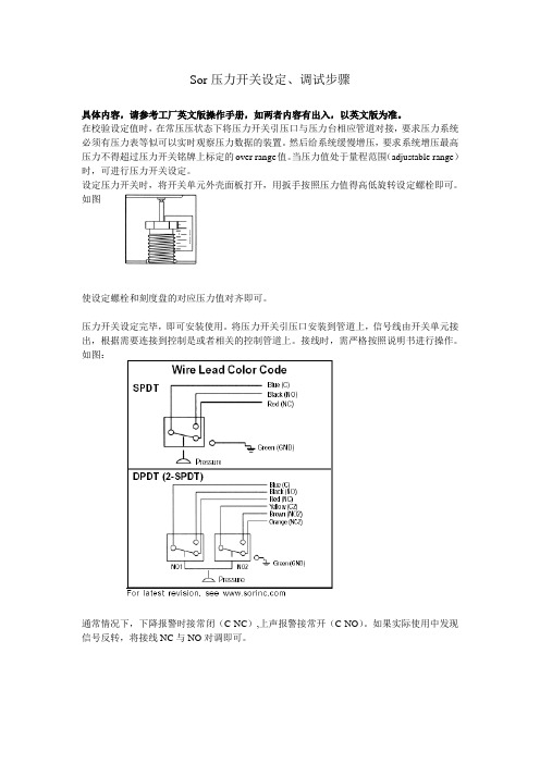
设定压力开关时,将开关单元外壳面板打开,用扳手按照压力值得高低旋转设定螺栓即可。
如图
使设定螺栓和刻度盘的对应压力值对齐即可。
压力开关设定完毕,即可安装使用。
将压力开关引压口安装到管道上,信号线由开关单元接出,根据需要连接到控制是或者相关的控制管道上。
接线时,需严格按照说明书进行操作。
如图:
通常情况下,下降报警时接常闭(C-NC),上声报警接常开(C-NO)。
如果实际使用中发现信号反转,将接线NC与NO对调即可。
SOR Inc. 调整式死带压力开关说明书
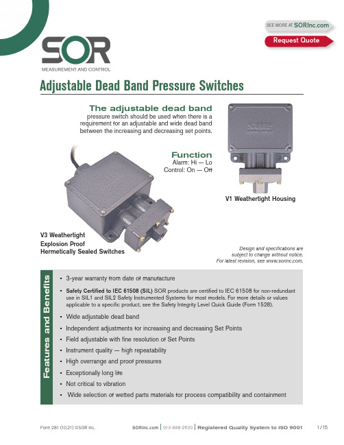
Adjustable Dead Band Pressure SwitchesThe adjustable dead bandpressure switch should be used when there is a requirement for an adjustable and wide dead band between the increasing and decreasing set points.FunctionAlarm: Hi — Lo Control: On — OffV1 Weathertight HousingDesign and specifications are subject to change without notice.For latest revision, see .V3 Weathertight Explosion ProofHermetically Sealed SwitchesSEE MORE AT Request QuoteThe SOR Adjustable Dead Band pressure switch incorporates two industry proven Static “O” Ring pressure sensing elements. Media pressure on the areas of the pistons counteracts the forces of the range springs — each adjustable by a separate adjusting nut — and moves the piston shafts to operate the lever assembly which, in turn, actuates and deactuates the electrical switching element. Each pressure sensing element of the Adjustable Dead Band pressure switch is a force balance piston-actuated assembly sealed by a flexible diaphragm and an o-ring that is static. The only wetted parts are the single pressure port, two diaphragms, and two o-rings all indicated with asterisks (*) in this illustration.Principles of OperationPressure SwitchesNo Pressure:Electrical switching element is deactuated.Pressure greater than decreasing Set Point but less than increasing Set Point. Electrical switching element remains deactuacted.Pressure equal to or greater than increasing Set Point: Electrical switching element is actuated.Pressure less than increasing Set Point but greater than decreasing Set Point: Electrical switching element remains actuated.Pressure equal to or less than decreasing Set Point: Electrical switching element is deactuated.*Pressure PortPrinciple SchematicThe lever assembly travel illustrated here has been exaggerated for clarity.Screw Terminal Block (Weathertight Model Only)Lever Assembly Calibration Scale Decreasing Set Point Adjusting Nut Piston Assembly Pressure Range Spring *Diaphragm *O-Ring*O-Ring *DiaphragmPressure Range SpringPiston Assembly HousingIncreasing Set PointAdjusting NutCalibration ScaleElectrical Switching Element (Explosion Proof Model has Hermetically Sealed Switching ElementCapsule)Actuation DeactuationPressure SwitchesHow to OrderHere is the SOR quick select model number trees that provide you with all the options to configure and order a product for your application.• Y ou must select a designator for each component.• Reference tables, charts and additional information is provided throughout the catalog to help you make your selections. See pages noted in the tree.Steps 1 through 6 are required. Step 7 is optional. Orders must have complete model numbers, i.e. each component must have a designator.ExampleModel No.If Agency Approved, Certified or Listed pressure switches are required, see page 10 for components that must be specified.Six adjustable dead band ranges are available. Each adjustable range is displayed on a grid (pages 5 and 6). Determine the correct adjustable range for the application by checking increasing and decreasing Set Point requirements against the tables. In the example below,a contact closure is required when pressure increases to 160 psi. The same contact mustopen when pressure decreases to 60 psi. Since 60 psi is within the blue field, the examplegrid range is correct for the application.When the correct range grid is selected, insert range designators and m from that grid into the model number.Step 1Find the specified increasing Set Point at the top of the graph.5V1-LA3Step 3Following the vertical line down from the increasing Set Point.Follow the horizontal line across from the decreasing Set Point. Any point within the blue field is acceptable.1st and 4th places in model number Increasing Set Point (psi)Increasing Set Point (psi)Increasing Set Point (psi)Increasing Set Point (psi)Increasing Set Point (psi)5V1-LA3-N6-C1A-YY Increasing Set Point (psi)Increasing Set Point (psi)Step 2: Housing5V1-LA3-N6-C1A-YY Use AG switching element; hermetically sealed SSPressure Switches Step 3: Switching Elements5V1-LA3-N6-C1A-YY1. The switching elements shownCertified. The DC current ratingmarked (*) is not UL Listed but hasbeen verified by testing and/orexperienced.2. The hermetically sealed switchingelement capsule is UL Listed, CSACertified and SAA Approved as asnap switch in accordance with thefollowing table.3. Consult the factory for availability ofSAA Approved units.Pressure Switches Step 5: Diaphragm and O-Ring5V1-LA3-N6-C1A-YY Notes Array 1. N4 diaphragm system is standard. It isnormally suitable for air, oil, water and non-corrosive processes.2. Other diaphragm and o-ring combinationsmay be available. Consult the factory or theSOR representative in your area for moreinformation.3. Wetted parts have been selected as repre-senting the most suitable commerciallyavailable material for use in the serviceintended. However, they do not constitute aguarantee against corrosion or permeation,since processes vary form plant to plant andconcentration of harmful fluids, gases orsolids vary from time to time in a givenprocess. Emperical experience by usersshould be the final guide. Alternate materialsbased on this are generally available.4. Specify N3 diaphragm system for high cyclerate, high shock applications where Buna-Nand TCP are compatible with the process.5. This table shows allowable minimum andmaximum temperature for o-rings.6. M9 diaphragm system is suggested forsteam applications up to 400o F.7. Dead bands are slightly higher when usingH, J, W, N3, or N6 series diaphragm options.Consult the factory.Step 6: Pressure Port5V1-LA3-N6-C1A-YYPressure SwitchesStep 7: Accessories5V1-LA3-N6-C1A-YYAgency ListingsThe following combinations only are available as approved, certified or listed by the agencies shown. Some components are for products not offered in this catalog. Certain components or combinations may acquire additional approval, certification or listing between print dates of this catalog. Contact the factory for the most current information.CSAEnclosure 4 (Weathertight)Pressure SwitchesT est CertificatesPressure Switches Glossary of T erms SOR recognizes that there is no industry convention with respect to terminology and definitions pertinent to pressure switches. This glossary applies to SOR Pressure Switches.Adjustable RangeThe span of pressure between upper and lower limits within which the pressure switch may be adjusted to actuate/deactuate.Dead BandThe difference in pressure between the increasing Set Point and decreasing Set Point. Decreasing Set PointThat discrete pressure at which the pressure switch is adjusted to deactuate on falling pressure. It must fall within the adjustable range. Hermetically SealedA welded steel capsule with glass-to-metal, factory-sealed, electrical leads that isolatesthe electrical switching element(s) from the environment.Increasing Set PointThat discrete pressure at which the pressure switch is adjusted to actuate on rising pressure. It must fall within the adjustable range. OverrangeThe maximum input pressure that may be continuously applied to the pressure switch without causing permanent change of Set Point, leakage or material failure.Pressure SwitchA bi-stable electromechanical device that actuates/deactuates one or more electrical switching element(s) at a predetermined discrete pressure/vacuum (Set Point) upon rising or falling pressure/vacuum.Proof PressureThe maximum input pressure that may be continuously applied to the pressure switch without causing leakage or catastrophic material failure. Permanent change of Set Point may occur, or destruction of the device may be rendered inoperative.RepeatabilityThe ability of a pressure switch to successively operate at a Set Point that is approached from a starting point in the same direction and returns to the starting point over three consecutive cycles to establish a pressure profile. The closeness of the measured Set Point values is normally expressed as a percentage of full scale (maximum adjustable range pressure). SPDT Switching ElementSingle-Pole, Double Throw (SPDT) has three connections: C — Common, NO — Normally Open and NC — Normally Closed, which allows the switching element to be electrically connected to the circuit in either NO orNC state.DPDT Switching ElementDPDT is two synchronized SPDT switching elements which actuate together at increasing Set Point and deactuate together at decreasing Set Point. Discrete SPDT switching elements allow two independent circuits to be switched;i.e., one AC and one DC.The synchronization linkage is factory set, and is not field adjustable. Synchronization is verified by connecting test lamps to the switching elements and observing them go “On” simultaneously at actuation and “Off” simultaneously at deactuation.|913-888-2630|Registered Quality System to ISO 900111/15 Form 281 (10.21) ©SOR Inc.Registered Quality System to ISO 9001 | 913-888-2630 | 12/15Form 281 (10.21) ©SOR Inc.Dimensions in this catalog are for reference only. They may be changed without notice. Contact the factory for certified drawings for a particular model number. Dimensions are expressed as millimeters over inches (Linear = mm/in.).Pipe Mounting Kit: PKJunction Box with T erminal Block:TBDrawing 0090300Drawing 0091353 | 913-888-2630 | Registered Quality System to ISO 900113/15Form 281 (10.21) ©SOR Inc. Junction Box with T erminal Block: HTWeightsActual shipping weights may vary from the charted values because of product material, configuration and packaging requirements.Drawing 0090763Registered Quality System to ISO 9001 | 913-888-2630 | 14/15Form 281 (10.21) ©SOR Inc.Hazardous Locations Contains Explosion Proof, Hermetically Sealed Switching Element Capsule: UL Listed, CSA Certified, ATEX and SAA Approved Housing Designator: V3Dimensions in this catalog are for reference only. They may be changed without notice. Contact the factory for certified drawings for a particular model number. Dimensions are expressed as millimetersDrawing 0090325Lenexa, KS USA |913-888-2630 |Fax 913-888-0767 |REGIONAL OFFICESChinaSOR China|Beijing, China|****************+86 10 5820 8767| Fax +86 10 5820 8770Middle EastSOR Measurement & Control Equipment Trading DMCC |Dubai, UAE*********************|+971 4 278 9632|Fax +1 913 312 3596Form 281 (10.21) ©SOR Inc.Registered Quality System to ISO 9001。
压力开关操作说明书

目录1 说明§1.1 重要说明§1.2 开关标识2 探测头安装§2.1 压力与真空探测头§2.2 差压探测头§2.3 温度探测头3 封装外壳的安装§3.1 “C”型外壳§3.2 “Z”型外壳§3.3 “V”型和“W”型外壳§3.4 “M”型外壳4 电气安装5 设定点调节6欧共体标准符合说明1 说明§1.1 重要说明* BETA压力开关属于精密仪器请正确放置或搬动。
BETA压力开关在达到设定点的(差压)压力或者温度时开关动作。
* 在按照说明书指示正确安装,该开关的设计与结构是完全免维护的。
切莫采用液态油或油脂润滑开关的任何部件。
* 除了更换外壳密封与安装支架外,不要移动或更换本开关的任何部件。
* 避免暴露在超高温、超低温、有侵蚀性环境中,-30~80℃为适宜温度。
* 调节螺丝有自锁性,所以在调节设定点后禁止封死调节螺丝。
* 安装前请详细检查铭牌上数据。
* 所有尺寸均以mm毫米标注。
* 如果您需要帮助请与供应商联系,开关只有在去污清洗后才能进行维护检修。
* 如果您需要额外的膜片O形圈和微动开关,请给出序列号向供应商购买。
* 开关的检修维护请由专业的仪表工程师实施。
除了更换膜片O形圈和微动开关以外,其它形式的检修维护有厂方执行。
* 非厂方检修维护的操作会影响产品本身的质量保证。
* 本章节的指导说明书的步骤也是安装步骤说明。
* 地基与工程环境的强烈振动可能会影响开关的正常功能。
§1.2 开关标识压力开关的铭牌上面标明了规格型号,4到7步可以确定该压力开关的设计组成,后缀的X+数字来表明特殊要求,该特殊要求可参照数据书。
外壳封装C1-P304L-S1N-B1-K1-Y-X2第一个字符即第一步标明了外壳封装形式:C、V、W、Z或M,参照图1-4和15。
探测头C1-P304L-S1N-B1-K1-Y-X2第一个和最后一个字符构成第二步标明了探测头规格及功能,参照图5-12和表1。
SOR差压开关101~121使用说明书

1、设定点调整端螺纹(未示)
2、高压端过程连接
3、低压端过程连接
4、严密密封的开关元件封壳
5、18AWG引线(未示)
6、1/2“NPT(M)电气连接
7、3/4”NPT(F)电气连接
8、全天候开关外壳
确保连线与所有的当地和国际的电气方面的规定一致,根据相关的国际和当地的安全规定来安装。
如果达到临界下降差压值,触点关闭,顺时针旋转设定点调整端直到触点改变。重复步骤2-5。
防爆型-AD外壳
JIS/RIIS认证的IIC-T6–JS外壳
CENELEC(BASEEFA)认证的EEx d IIC T6-CL附件
1、凸边帽遮住设定点调整端
2、高压端过程连接1/4”NPT(F)[1/2”NPT(F)]
参考SOR样本459的尺寸,确切的尺寸图,请联系SOR工厂。
标定
普通标定:旋转设定点调整端从而直线移动弹簧引导盘达到标定比例尺上所示的需要的设定点
电气连接
确保连线与所有的当地和国际的电气方面的规定一致,根据相关的国际和当地的安全规定来安装。
警告:在打开防爆型开关的上盖之前,必须断开电源。否则,会导致严重的人员伤害或财产的损坏。
进行电气连接时,要避免电器开关元件的移动。
电气连接不是螺纹接线端部分外壳内部的绝缘板确定。参考图1所示的不同颜色电线的连线图。
精密标定步骤
精密标定步骤依靠稳定的系统压力。在模拟的压力应用场合进行差压开关的标定可以加强设定点精度。建议使用下面的测试仪器。
1、差压计
2、可变压力源
3、排放和均衡阀
4、测试灯或欧姆表
确定在升高或降低设定点时是否有临界设定点的出现,使用相应的程序进行调校。
SOR简介——精选推荐
SOR简介SOR开关简介SOR公司是美国著名的压⼒开关⽣产⼚商,是世界上唯⼀的可⽣产压⼒、差压、温度、液位及流量开关的⼚商,它⽣产的开关⼴泛应⽤于电⼚及⽯油化⼯领域。
⽬前该⼚商⽣产的多种类型⾼品质开关,在我国的⼤、中型⽕⼒发电⼚有着极为⼴泛的使⽤,对电⼚发电机组系统的保护和可靠运⾏起到了很好的作⽤。
SOR开关符合国际质量标准ISO9001,此产品的⾼可靠性和精度得到所有⽤户的肯定。
在2001年年度中,国内的300MW以上⽕⼒发电新建机组⼏乎全部采⽤SOR逻辑开关来对全⼚系统进⾏保护。
由此可见,此品牌开关在电⼒⾏业的⽤户信誉是其他品牌开关所⽆法⽐拟的。
1、压⼒开关⼯作范围⼴(-15--4000psi),设点稳定,重复率⾼,死区⼩,⼏乎不受温度影响。
开关品种齐全,范围设计合理,并对各种使⽤环境均有专业⼯况。
2、差压开关重复率⾼,死区⼩,受温度及静⼒影响⼩。
107系列是低压差压开关,其设点稳定,精度⾼,是电⼚的炉保系统应⽤⼴泛的⼀种差压开关。
102/103系列可承受较⾼静压,⽽所测压差可很微⼩,且精确度很⾼,故在电⼚管道滤⽹上⼴泛应⽤。
3、温度开关受环境温度影响⼩,反应快速,重复率⾼,死区⼩。
⼯作范围:-45℃--540℃4、液位开关有机械式和电⼦式等多种形式,其机械式开关利⽤磁吸合原理,⼯作可靠,⽆毒,不使⽤⽔银等有毒物质,完全符合当今的环保要求。
其独特的陶瓷开关,使SOR的液位开关的适⽤温度得以⼤⼤提⾼,完全满⾜电⼒⾏业的各种⼯况。
5、超声波物位变送器-⾼能量在苛刻的⼯况下(粉尘,泡沫,蒸汽)有很强的穿透能⼒⾼能量的声波确保所接收的回波在能量衰减后仍可⽤于测量-低频低频声脉冲波⽐⾼频有更强的穿透⼒,距离更远低频⽐⾼频受到更少的质体⼲扰最⼤的测量范围可达80m-⾃动增益调节⽆需进⾏空罐操作来消除虚假回波的⼲扰,始终能够锁定真实物位回波,不会造成回波信号的丢失唯⼀可根据⼯况情况⾃⾏调节的产品上海外⾼桥电⼚4×300MW √ √ √上海吴泾热电⼚2×300MW √ √上海华能⽯洞⼝第⼆电⼚2×600MW √ √上海杨树浦电⼚2×125MW √ √上海闸北电⼚4×100MW燃机 √上海⾦⼭⽯化⾃备电⼚2×200MW √ √浙江嘉兴电⼚⼀期2×300MW √ √浙江嘉兴电⼚⼆期5#/6#机2×600MW √浙江台州电⼚2×300MW √ √浙江北仑港电⼚2×600MW √ √浙江宁波纸⼚⾃备电⼚2×50MW √浙江温州电⼚2×300MW √浙江长兴电⼚2×300MW √浙江秦⼭核电⼚⼆期2×600MW √ √√浙江秦⼭核电⼚三期2×600MW √江苏利港电⼚2×600MW √江苏徐塘电⼚(以⼤代⼩)2×300MW √ √江苏彭城电⼚2×300MW √江苏南化⾃备电⼚2×50MW √√江苏扬⼦⽯化⾃备电⼚2×125MW √江苏⾦陵⽯化⾃备电⼚2×50MW √√江苏华能南京电⼚2×300MW √江苏华能南通电⼚2×300MW √ √江苏华能太仓电⼚2×300MW √江苏华能淮阴电⼚2×200MW √江苏华能淮阴电⼚⼆期2×300MW √ √江苏新海电⼚2×125MW √江苏南京下关电⼚2×135MW √江苏镇江⾼姿电⼚4×135MW √√江苏盐城电⼚2×135MW √江苏扬州电⼚2×200MW √√江苏扬州第⼆电⼚2×600MW √√江苏江阴夏港苏龙电⼚4×135MW √江苏太仓港环保电⼚⼆期2×300MW √√江苏太仓港环保电⼚三期2×300MW √√江苏南通天⽣港电⼚4×135MW √√江苏南通天⽣港电⼚⼆期2×300MW √√江苏南京扳桥电⼚2×135MW √江苏镇江谏壁电⼚2×300MW √√江苏贾旺电⼚4×135MW √√√江苏⼤屯发电⼚2×135MW √江苏华润常熟电⼚3×600MW √√安徽平圩电⼚2×600MW √安徽⽥家庵电⼚1×300MW √安徽铜陵电⼚1×300MW √√安徽淮北电⼚2×300MW √安徽洛河电⼚4×300MW √安徽马钢⾃备电⼚2×50MW √√ √安徽安庆电⼚2×300MW √福建厦门嵩屿电⼚2×300MW √√√ 福建漳平电⼚2×100MW √福建邵武电⼚2×125MW √⼴东华能汕头电⼚2×300MW √ √⼴东珠江电⼚2×300MW √ √⼴东沙⾓B⼚,C⼚2×600MW √ √⼴东珠海电⼚2×600MW √ √⼤亚湾核电站 √湖南⽯门电⼚2×300MW √ √湖南湘潭电⼚2×300MW √ √湖南株州电⼚2×300MW √ √湖南益阳电⼚2×300MW √ √湖南鲤鱼江电⼚2×300MW √ √湖北襄樊电⼚4×300MW √√湖北汉川电⼚2×300MW √√湖北武钢⾃备电⼚2×200MW √ √湖北黄⽯电⼚2×300MW √√湖北蒲圻电⼚2×300MW √河南⾸阳⼭电⼚2×300MW √ √河南登封电⼚2×300MW √ √√河南永城电⼚2×300MW √ √河南新乡电⼚2×135MW √河南神⽕电⼚2×135MW √河南周⼝电⼚2×135MW √⼭东⽯横电⼚4×300MW √⼭东胜利油⽥⾃备电⼚2×300MW √⼭西阳泉电⼚2×300MW √√⼭西太原第⼀热电⼚2×300MW √√⼭西太原第⼀热电⼚⼆期2×600MW √√⼭西河曲电⼚⼀期2×600MW √ √北京⽯景⼭热电⼚2×100MW √北京第⼆热电⼚2×200MW √河北沙岭⼦电⼚4×300MW √√河北定州电⼚2×600MW √ √天津⼤港电⼚2×300MW √天津⼤唐盘⼭电⼚⼆期2×600MW √ √哈尔滨第三热电⼚2×300MW √√吉林省吉林热电⼚2×200MW √华能⼤连电⼚2×300MW √√陕西渭河电⼚2×300MW √陕西蒲城电⼚2×300MW √√√陕西神⽊电⼚2×100MW √√陕西宝鸡电⼚4×300MW √陕西西郊热电⼚2×300MW √√⽢肃靖远电⼚2×300MW √√⽢肃西固电⼚2×125MW √√⽢肃平凉电⼚4×300MW √√内蒙达旗电⼚2×300MW √√√内蒙国华准格尔电⼚2×600MW √ √内蒙托克多电⼚⼆期2×600MW √ √宁夏⼤坝电⼚2×300MW √√云南曲靖电⼚2×300MW √√巴基斯坦恰希玛核电站⼀期2×350MW √巴基斯坦⽊扎法⼽电⼚2×300MW √越南协福电⼚2×100MW √√√伊朗萨汉姆燃机电⼚2×350MW √√孟加拉巴库电⼚2×125MW √√主要OEM配套⼚家名称压⼒开关液位开关电⼦式液位产品北京良乡 √√北京重型机器⼚ √√ √上海汽轮机⼚ √√上海电机⼚ √√ 上海锅炉⼚ √上海电站辅机⼚√√上海电⼒修造⼚ √上海⽔泵⼚ √上海⿎风机⼚ √√上海重型机器⼚ √√杭州汽轮机⼚ √√杭州锅炉⼚√东⽅汽轮机⼚ √东⽅电机⼚ √东⽅锅炉⼚ √哈尔滨汽轮机⼚ √哈尔滨电机⼚ √哈尔滨锅炉⼚ √沈阳⿎风机⼚ √√沈阳⽔泵⼚ √。
- 1、下载文档前请自行甄别文档内容的完整性,平台不提供额外的编辑、内容补充、找答案等附加服务。
- 2、"仅部分预览"的文档,不可在线预览部分如存在完整性等问题,可反馈申请退款(可完整预览的文档不适用该条件!)。
- 3、如文档侵犯您的权益,请联系客服反馈,我们会尽快为您处理(人工客服工作时间:9:00-18:30)。
概述
本说明书是关于SOR 压力开关在安装、过程联接、 电气联接和调校方面的说明,此种形式压力开关不 推荐用于存在高冲击压且高频率循环的高液压工作 场合。
注意:如果您发现某台开关有损坏,请尽快与工厂 或SOR 产品当地服务代表联系,以获得返修登记号 码,如果该产品无法返回工厂维修,应由授权的产 品服务代表提供现场服务,请与工厂或SOR 公司当 地服务代表联系技术支持事宜。
设计与规范的改动请恕不另行通知。
电气联接
警告:在危险环境下开启防爆型开关,在盖移动前一定要保证电源已被断开,否则会导致严重的个人伤害和巨大的工厂损毁。
在开关壳内防置过多的导线或不当的联接可能会防碍开关正常的工作。
外壳型式 电气接口 接点 接线标志
无
螺丝端子 贴于绝缘纸上 导线
颜色区别、标识 所有其它型式
3/4NPT(F) 或 M20X 1.5(F) 特殊指定除外
螺丝端子 贴于绝缘纸上 导线 颜色区别、标识 端子条块
贴于绝缘纸上
第1页/ 2页 ISO 9001质量体系认证
真空开关(接线图解)
当设定点为真空时,参
照图一 当设定点为正压时,参照图二
图一
图二
兰(公用) 黑(常开) 红(常闭) 绿(地线)
兰(公用) 黑(常开) 红(常闭) 黄(公用2) 棕(常开2) 桔红(常闭2) 绿(地线)
导线颜色标识
压力开关 使用说明书
安装
1.用两个适当长度的1/4英寸螺栓,牢固地将开关外壳通过安装孔与仪表架或安装柱装配
在一起。
2.不推荐通压力接口或电气接口的在线安装。
3.建议安装位置为电气接口竖直向下,以避免收集冷凝液,尽管如此,开关仍可全位置安
装。
保证导线的电气性能符合所有应用的国家和场合,并且根据相关国家和场合的安全要求安装产品。
过程联接
采用两个扳手安全地将引压管与压力接口联接:一个扳手夹住六角形压力接口,另一个扳手旋紧引压管或管接头。
重要:小心勿使压力接口松,压力接头从壳体上脱落。
警告:将外壳安装平板表面可能会导致外壳受到扭力,从而使压力开关不能正常工作。
调校
警告:在工厂开关元素已在壳体内被精确定位,开关触点行程也已调至最佳状态,任何现场的不当移动和替换都会降低精度,导致开关不能正常工作,除非工厂认为程序是允许的。
常规开关(回程差固定型)
使用3/4英寸英寸开口扳手,顺时针旋六角形调节螺母可升高设定值;逆时针则减小设定值。
从调节螺母上表面垂直读出壳体内表面贴的调节范围所示值,即可得到粗略设定值,若要求精确设定值,则需标准压力源,连续校验仪和0.25%精度的压力表。
回程差可调型开关
使用常规开关调校方法(上述)设定希望的降压设定点,升压设定点可转动开关元件上的白色拨轮来设定。
设在A为最小回程差;设在F为最大回程差;调节量超过E点会影响精度。
参考尺寸图见SOR样本(Form 216)。
精确尺寸图,请联络工厂。
第2页/ 2页ISO 9001质量体系认证。
