以太网业务g属性
40G 100G以太网标准正式颁布
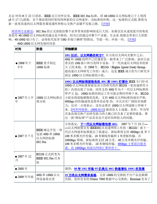
北京时间6月22日消息,IEEE近日对外宣布,IEEE 802.3ba标准,即40/100G以太网标准已于上周四(6月17日)获批,首个规范将同时使用两种新的以太网速率。
该标准组织称,这一标准的正式批准将为新一波更高速的以太网服务器连通性和核心交换产品铺平发展之路。
[详细]
网界网专家解读:802.3ba 的正式获批给整个业界带来的影响将是巨大的。
如果仅仅从速度提升的角度来看待40/100G以太网标准的通过是不够的。
因为它的通过对整个产业链、生态系统都会带来巨大的影响。
40/100G端口有了,必将取代很多“10G多端口捆绑”的情况,节能一些,环保一些。
[详细]。
PON技术原理
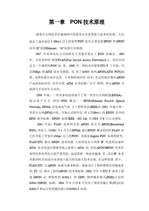
第一章PON技术原理随着以太网技术在城域网中的普及以及宽带接入技术的发展,人们提出了速率高达1 Gbit/s 以上的宽带PON 技术,主要包括EPON 和GPON 技术:“E”是指E thernet,“G”是指吉比特级。
1987 年英国电信公司的研究人员最早提出了PON 的概念。
1995 年,全业务网络联盟F SAN(Full Service Access Network)成立,旨在共同定义一个通用的PON 标准。
1998 年,国际电信联盟ITU-T 工作组,以155Mbps 的ATM 技术为基础,发布了G.983 系列APON(ATM PON)标准。
这种标准目前在北美、日本和欧洲应用较多,在这些地区都有A PON 产品的实际应用。
但在中国,ATM 本身的推广并不顺利,所以A PON 在我国几乎没有什么应用。
2000 年底,一些设备制造商成立了第一英里以太网联盟(EFMA),提出基于以太网的PON 概念——EPON(Ethernet Passive Optical Network)。
EFMA 还促成电气电子工程师协会(IEEE)在2001 年成立第一英里以太网(EFM)小组,开始正式研究包括1.25Gbit/s 的EPON 在内的EFM 相关标准。
EPON 标准IEEE 802.3ah 在2004 年6月正式颁布。
2001 年底,FSAN 更新网页把APON 更名为BPON(Broadband PON)。
实际上,在2001 年1月左右E FMA 提出E PON 概念的同时,FSAN 也已经开始了带宽在1Gbps 以上的P ON,也就是G igabit PON 标准的研究。
FSAN/ITU 推出GPON 技术的最大原因是由于网络IP 化进程加速和ATM 技术的逐步萎缩导致之前基于ATM 技术的A PON/BPON 技术在商用化和实用化方面严重受阻,迫切需要一种高传输速率、适宜I P 业务承载同时具有综合业务接入能力的光接入技术出现。
网络协议词典-G
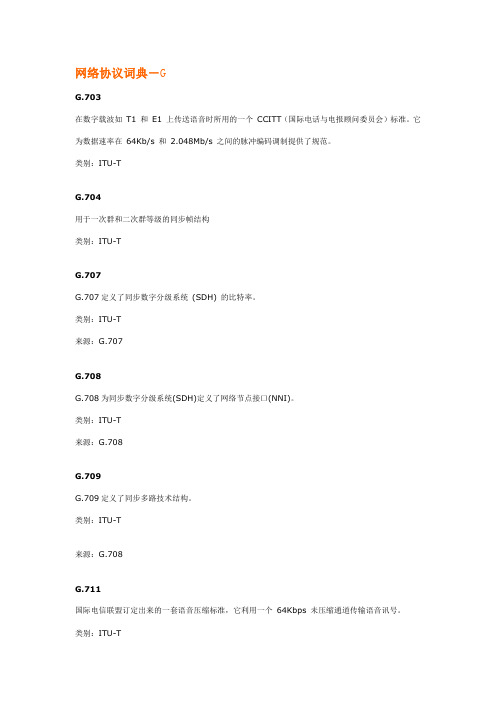
网络协议词典-GG.703在数字载波如 T1 和E1 上传送语音时所用的一个CCITT(国际电话与电报顾问委员会)标准。
它为数据速率在64Kb/s 和2.048Mb/s 之间的脉冲编码调制提供了规范。
类别:ITU-TG.704用于一次群和二次群等级的同步帧结构类别:ITU-TG.707G.707定义了同步数字分级系统 (SDH) 的比特率。
类别:ITU-T来源:G.707G.708G.708为同步数字分级系统(SDH)定义了网络节点接口(NNI)。
类别:ITU-T来源:G.708G.709G.709定义了同步多路技术结构。
类别:ITU-T来源:G.708G.711国际电信联盟订定出来的一套语音压缩标准,它利用一个64Kbps 未压缩通道传输语音讯号。
类别:ITU-T一个代码转换系统。
它使用ADPCM 转换技术,实现64 kb/s A 律或μ 律PCM 速率和32 kb/s 速率之间的相互转换。
类别:ITU-TG.722数据率为64kb/s 的7kHz 声音信号编码— 7kHz Audio-coding with 64kb/s。
这个标准把话音信号的质量由电话质量提高到 AM 无线电广播质量,而其数据传输率仍保持为64kb/s。
类别:ITU-TG.723 or G.723.1ITU-T 建议的应用于低速率多媒体服务中语音或其它音频信号的压缩算法,例如:H.323、H.324系统。
类别:ITU-TG.72640、32、24、16kbit/s 自适应差分脉冲编码调制 ADPCM类别:ITU-TG.7275-、4-、3-和2-bit/s 嵌入式自适应差分脉冲编码调制ADPCM类别:ITU-TG.728利用低延迟代码线性预测以16 bit/s 进行语音编码类别:ITU-T利用共扼结构-代数激励编码线性预测(CS-ACELP)以8bit/s 进行语音编码类别:ITU-TG.7xxG.7xx是用于视频压缩和解压缩ITU-T标准的一个组。
中国电信(MSTP)以太网专线业务介绍
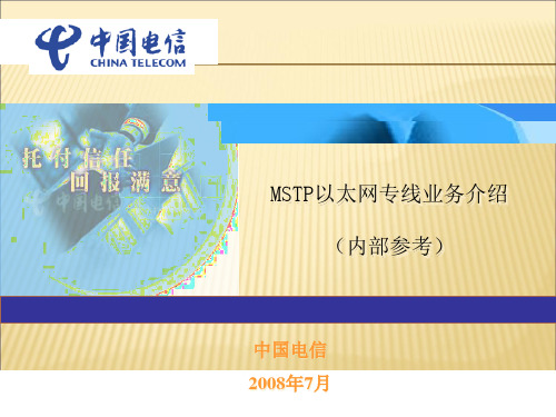
MSTP:Multi-Service Transport Platform
基于SDH的多业务传送节点(MSTP)是指,基于SDH平台,同时实现TDM业务、 ATM业务、以太网业务等的接入、处理和传送,提供统一网管的多业务节点。
基于SDH的多业务传送节点除应具有标准SDH传送节点所具有的功能外,还具有以下 主要功能特征:
20,000 56,000 160,000 210,000 440,000 1,230,000 3,440,000
亚洲各国
100,000 280,000 780,000 900,000 2,200,000 6,150,000 17,210,000
欧、美、澳、非各国
100,000 280,000 780,000 900,000 2,200,000 6,150,000 17,210,000
交流
通信系统的构造及信息服务的 形式
a b
A B C
简单通信的系统构造
信息服务的2种基本使用形式: 1: a —B—A—A’—B’—b 如:打电话、QQ聊天(特点:2终端同时启用) 2: a —B—A 2’:b —B’—A’ 如:发(收)邮件,
政府、企业更新网页(市民、顾客浏览) (特点:2终端不必同时启用)
MSTP是(从应用角度看): 为客户的通信系统搭建组网通道的某一网元之一。
MSTP通道搭建的带宽
2M*N,最高可达100M乃至1G
(随着客户需求的提高,带宽可在线调整)
MSTP通道搭建的总体结构及接入方式
总体结构
分点的接入
关于MSTP(2)
MSTP 的长与短 宜组建:点到点专线、点到多点专线 对于“多点到多点组网”,建议通过城域网或CN2平台去搭建。 (注:还要留意各种板的汇聚比) MSTP通道搭建的地域限制: 1、本地组网业务; 2、广东省内长途业务; 3、根据省公司现阶段要求,仅受理北京、上海、江苏、浙江等沿 海发达省份的跨省业务。
U2000中以太网业务的单板知识和故障处理

PORT
VB3
VB2
以太网基本术语-Tag 属性
Tag属性可对信号包进行标示,目前有三种端口Tag属性: Tag aware, Access和 Hybrid。
Tag aware:端口设臵成Tag aware后,该端口可对带有VLAN ID
EFT8A 622 Mbit/s
自身实现8路电口以太网信 号接入;
配合出线板
无
配合ETF8实现16路电口以 太网信号接入;
配合EFF8实现8路光口以太 网信号、8路电口以太网信 号接入;
EFT8A不支持接口板出线。 EPL
无
支持业务类型 业务帧格式 封装格式
Ethernet II、IEEE 802.3,IEEE 802.1qTAG,支持64Byte~9600Byte帧长,支持 9600字节长Jumbo帧 HDLC/LAPS/GFP-F
可对外部物理端口以及vctrunk的tag属性外部物理端口vctrunkegs2egs2statactprogsrvlink1act1act2link2classlaserproduct以太网单元egt2egs2statactprogsrv指示灯link1act1link1act1link2act2指示灯指示灯颜色状态具体描述连接状态指示灯link1第1路ge端口和对端设备链路建立失败数据收发指示灯act1闪烁第1路ge端口和对端设备正在收发数据第1路ge端口和对端设备没有数据收发classlaserproduct以太网单元功能以太网透明传输单板以太网电接口rj45最远传送距离100米支持lptlcas功能以太网单元功能以太网二层交换单板以太网电接口rj45最远传送距离100米支持epleplanevplevplan及qos支持lptlcas静态mpls功能emr0emr0statactprogsrvlinkactclasslaserproductfe1fe2fe3fe4以太网单元emr0egr2wrapsteeringwrapsteeringfe端口rj45fe端口rj45连接器ge端口lcge端口lc连接器ems4ems4statactprogsrvclasslaserproductlinkact以太网单元ems4egs4支持eplevplqinqeplan业务以及qos支持64byte9216byte帧长支持9216字节长的jumbo帧支持bpsppsqinqlcasethoam纯网桥ge端口lcge端口lc连接器以太网单板保护及应用以太网基本术语单板外部以太网物理接口亦称作客户侧接口或用户侧接口目前常用接口为10mfege
第三章_PON技术

第三章PON技术第一节PON技术原理随着以太网技术在城域网中的普及以及宽带接入技术的发展,人们提出了速率高达1Gbit/s以上的宽带PON技术,主要包括EPON和GPON技术:“E”是指Ethernet,“G”是指吉比特级。
1987年英国电信公司的研究人员最早提出了PON的概念。
1995年,全业务网络联盟FSAN(Full Service Access Network)成立,旨在共同定义一个通用的 PON 标准。
1998年,国际电信联盟ITU-T工作组,以155Mbps的ATM技术为基础,发布了G.983系列APON(ATMPON)标准。
这种标准目前在北美、日本和欧洲应用较多,在这些地区都有APON产品的实际应用。
但在中国,ATM本身的推广并不顺利,所以APON在我国几乎没有什么应用。
2000年底,一些设备制造商成立了第一英里以太网联盟(EFMA),提出基于以太网的PON概念——EPON(Ethernet Passive Optical Network)。
EFMA还促成电气电子工程师协会(IEEE)在2001年成立第一英里以太网(EFM)小组,开始正式研究包括1.25Gbit/s的EPON在内的EFM相关标准。
EPON标准IEEE 802.3ah在2004年6月正式颁布。
2001年底,FSAN更新网页把APON更名为BPON(Broadband PON)。
实际上,在2001年1月左右EFMA提出EPON概念的同时,FSAN也已经开始了带宽在1Gbps以上的PON,也就是Gigabit PON标准的研究。
FSAN/ITU推出GPON技术的最大原因是由于网络IP化进程加速和ATM技术的逐步萎缩导致之前基于ATM技术的APON/BPON技术在商用化和实用化方面严重受阻,迫切需要一种高传输速率、适宜IP业务承载同时具有综合业务接入能力的光接入技术出现。
在这样的背景下,FSAN/ITU以APON 标准为基本框架,重新设计了新的物理层传输速率和TC层,推出了新的GPON技术和标准。
知识点理顺:传输设备中的 GE FE POS 接口
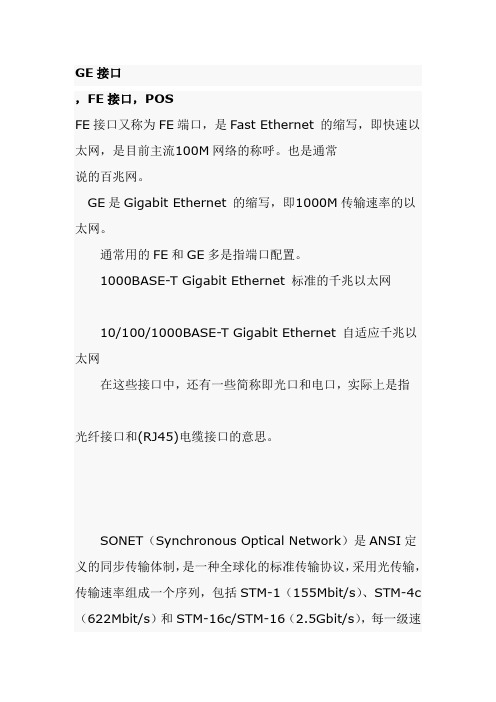
GE接口,FE接口,POSFE接口又称为FE端口,是Fast Ethernet 的缩写,即快速以太网,是目前主流100M网络的称呼。
也是通常说的百兆网。
GE是Gigabit Ethernet 的缩写,即1000M传输速率的以太网。
/i"M1Z2C#i$c.K5q通常用的FE和GE多是指端口配置。
1000BASE-T Gigabit Ethernet 标准的千兆以太网MSCBSC 移动通信论坛A2W:C8x#t'g10/100/1000BASE-T Gigabit Ethernet 自适应千兆以太网在这些接口中,还有一些简称即光口和电口,实际上是指| 国内领先的通信技术论坛/^8w7p-h$i光纤接口和(RJ45)电缆接口的意思。
mscbsc 移动通信论坛拥有30万通信专业人员,超过50万份GSM/3G等通信技术资料,是国内领先专注于通信技术和通信人生活的社区。
/Q+^9V)R!R3E*a6QSONET(Synchronous Optical Network)是ANSI定义的同步传输体制,是一种全球化的标准传输协议,采用光传输,传输速率组成一个序列,包括STM-1(155Mbit/s)、STM-4c (622Mbit/s)和STM-16c/STM-16(2.5Gbit/s),每一级速率都是较低一级的4倍。
由于是同步信号,因此SDH可以方便地实现多路信号的复用。
mscbsc 移动通信论坛拥有30万通信专业人员,超过50万份GSM/3G等通信技术资料,是国内领先专注于通信技术和通信人生活的社区。
$W(o1j0?.v%p:I8M8O SDH(Synchronous Digital Hierarchy)是CCITT(现在的ITU-T)定义的,使用SONET速率的一个子集。
路由器常见的接口有:通用串行接口(通过电缆转换成RS232DTE/DCE接口、V35DTE/DCE接口、X.21DTE/DCE接口、RS449DTE/DCE接口和EIA530DTE接口等)、10M以太网接口、快速以太网接口、10/100自适应以太网接口、千兆以太网接口、ATM接口(2M、25M、155M、633M 等)、POS接口(155M、622M等)、TokenRing接口、FDDI 接口、E1/TI接口、E3/T3接口、ISDN接口等。
精选新版L1考试复习题库588题(含答案)
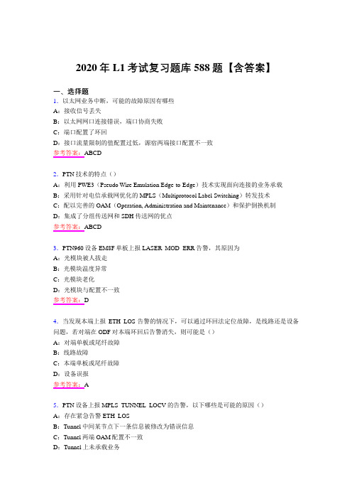
2020年L1考试复习题库588题【含答案】一、选择题1.以太网业务中断,可能的故障原因有哪些A:接收信号丢失B:以太网网口连接错误,端口协商失败C:端口配置了环回D:接口流量限制的值配置过低,源宿两端接口配置不一致参考答案:ABCD2.PTN技术的特点()A:利用PWE3(Pseudo Wire Emulation Edge-to-Edge)技术实现面向连接的业务承载B:采用针对电信承载网优化的MPLS(Multiprotocol Label Switching)转发技术C:配以完善的OAM(Operation, Administration and Maintenance)和保护倒换机制D:集成了分组传送网和SDH传送网的优点参考答案:ABCD3.PTN960设备EM8F单板上报LASER_MOD_ERR告警,其原因为A:光模块被人拔走B:光模块温度异常C:光模块老化D:光模块与配置不一致参考答案:D4.当发现本端上报ETH_LOS告警的情况下,可以通过环回法定位故障,是线路还是设备问题,若对端在ODF对本端环回后告警消失,则可能是()A:对端单板或尾纤故障B:线路故障C:本端单板或尾纤故障D:设备误报参考答案:A5.PTN设备上报MPLS_TUNNEL_LOCV的告警,以下哪些是可能的原因()A:存在紧急告警ETH_LOSB:Tunnel中间某节点下一条信息被修改为错误信息C:Tunnel两端OAM配置不一致D:Tunnel上未承载业务参考答案:ABC6.PTN设备处理告警常用方法包括()A:告警分析法B:性能统计分析法C:环回法D:配置数据分析法参考答案:ABCD7.聚合组成员失效的情况下,对于非负载分担模式下可能会造成()A:带宽不够,持续丢包B:引发链路倒换,短暂丢包C:没有影响D:业务中断参考答案:B8.关于PTN支持的业务描述正确的是A:目前PTN支持多个A TM连接汇聚映射到一个PW中B:目前PTN不支持多个CES业务汇聚映射到一个PW中C:PTN 设备间可以建立ATM PW 来仿真端到端的A TM 业务D:目前PTN支持多个以太业务汇聚映射到一个PW中参考答案:ABCD9.BUS_ERR告警产生的可能原因不包括A:软件版本不匹配B:业务板故障C:交叉芯片损坏D:数据配置错误参考答案:D10.在配置Tunnel的时候可以通过()避免主备同路由A:配置OAM属性B:配置APS属性C:配置路由约束D:配置内外层标签参考答案:C11.网元ID(NEID)规划的原则不包括A:每个网元必须有一个独立的网元IDB:同一个DCN管理网中不能有网元ID相同的网元C:环形网络中,网元的ID号应该沿环网的同一个方向逐一递增D:网元ID为32位的IP地址格式参考答案:D12.PTN的网元间DCN自通特性,默认使用了哪个VLAN号进行了网元间DCN自通A:1024B:2048C:4094D:4096参考答案:C13.PTN汇聚层普遍速率为多大A:FEB:GEC:10GED:40GE参考答案:C14.2G业务在PTN网络上的承载方式为A:CESB:ETHC:VPLSD:L3VPN参考答案:A15.使用VPLS业务承载大客户业务,其MAC地址容限默认为A:128B:256C:512D:1024参考答案:C16.LTE业务配置PW APS保护,其Qos配置的CIR带宽为A:2MB:20MC:40MD:100M参考答案:C17.PTN网络承载2G业务,其基站接入侧采用()接口A:E1B:FEC:GED:10GE参考答案:A18.汇聚环配置环网保护,在汇聚环链路中断时,绑定该环网的Tunnel如何倒换A:链路故障的两个节点绕行B:入环节点和出环节点直达路由C:Tunnel APS倒换D:没有影响参考答案:A19.设置告警过滤是指告警不上报到哪里A:U2000的服务器B:U2000的客户端C:网元主控板D:网元单板参考答案:B20.可以通过存量-单板过滤全网导出全网单板信息,其中不包括A:单板BOM编码B:单板条形码C:网元LSR_IDD:单板型号参考答案:C21.PTN网元升级一般选择哪种方式升级A:模拟包升级B:板级升级C:包升级/降级D:补丁更新参考答案:C22.网元上存在哪种告警不可以进行升级操作A:ETH_LOSB:MPSL_TUNNEL_LOCVC:COMMUNL_FAILD:HARD_BAD参考答案:CD23.配置以太网时有三种tag属性,Tag aware、Acess和Hybrid。
百兆以太网ICIP101G规格书
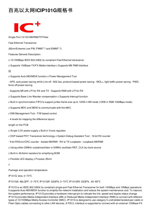
百兆以太⽹ICIP101G规格书Single Port 10/100 MII/RMII/TP/FiberFast Ethernet Transceiver(85nm/Extreme Low PW, PWMT ? and EMIMT ?)Features General Descriptionz 10/100Mbps IEEE 802.3/802.3u compliant Fast Ethernet transceiverz Supports 100Base-TX/FX Media Interface z Supports MII/ RMII Interfacez Supports Auto MDI/MDIX function z Power Management Tool- APS, auto power saving while Link-off - 802.3az, protocol based power saving - WOL+, light traffic power saving - PWD, force-off power saving- Supports MII with LPI for RX and TX - Supports RMII with LPI for RXz Supports Base Line Wander compensation z Supports Interrupt functionz Built in synchronization FIFO to support jumbo frame size up to 12KB in MII mode (10KB in RMII 100Mbps mode)z Supports MDC and MDIO to communicate with the MACz EMI Management Tool - F/W based control- 4 levels for mapping the difference layoutlength on the PCBz Single 3.3V power supply z Built-in Vcore regulatorz DSP-based PHY Transceiver technology z System Debug Assistant Tool - 16 bit RX counter- 9 bit RXError/CRC counter - Isolate MII/RMII - RX to TX Loopback - Loopback MII/RMIIz Using either 25MHz crystal/oscillator or 50MHz oscillator REF_CLK as clock sourcez Built-in 49.9ohm resistors for simplifying BOMz Flexible LED display z Process: 85nmzPackage and operation temperatureIP101G: dice, 0~70℃IP101GA: 48LQFP , 0~70℃ IP101GR: 32QFN, 0~70℃ IP101GRI: 32QFN, -40~85℃IP101G is an IEEE 802.3/802.3u compliant single-port Fast Ethernet Transceiver for both 100Mbps and 10Mbps operations. It supports Auto MDI/MDIX function to simplify the network installation and reduce the system maintenance cost. To improve the system performance, IP101G provides a hardware interrupt pin to indicate the link, speed and duplex status change.IP101G provides Media Independent Interface (MII) or Reduced Media Independent Interface (RMII) to connect with different types of 10/100Mbps Media Access Controller (MAC). IP101G is designed to use category 5 unshielded twisted-pair cable or Fiber-Optic cables connecting to other LAN devices. A PECL interface is supported to connect with an external 100Base-FXfiber optical transceiver. Except good performance, reliability, rich power saving method and extreme low operating current, IP101G provides a serial tool for system designers to complete their projects easily. They are System Debug Assistant Tool and EMI Management Tool.IP101G is fabricated with advanced CMOS (85nm) technology and design is based onIC Plus’s 5th Ethernet-PHY architecture, this feature makes IP101G consumes very low power. Such as in the full load operation (100Mbps_FDX), it only takes below 0.15W. IP101GA / IP101GR&IP101GRI are available in 48LQFP/32QFN, lead-free package.* EMIMT: Patent under apply.Application■ NAS■ Network Printers and Servers ■ IP Set-Top Box ■IP/Smart TV■ Game console■ IP and Video Phone ■ PoE■Telecom Fiber deviceTable Of ContentsTable Of Contents (2)List of Figures (4)List of Tables (5)Revision History (6)Features comparison between IP101G and IP101A/IP101AH (7)Transmit and Receive Data Path Block Diagram (8)1Pin diagram (9)2Dice pad information (11)3Pin description (12)3.1IP101GA pin description (12)3.2IP101GR/GRI pin description (16)4Register Descriptions (19)4.1Register Page mode Control Register (20)4.2MII Registers (20)4.3MMD Control Register (30)4.4MMD Data Register (31)4.5RX Counter Register (34)4.6LED Pin Control Register (35)4.7WOL+ Control Register (36)4.8UTP PHY Specific Control Register (39)4.9Digital IO Pin Control Register (39)5Function Description (41)5.1Major Functional Block Description (41)5.1.1Transmission Description (41)5.1.2MII and Management Control Interface (42)5.1.3RMII Interface (43)5.1.4Flexible Clock Source (45)5.1.5Auto-Negotiation and Related Information (45) 5.1.6Auto-MDIX function (46)5.2PHY Address Configuration (46)5.3Power Management Tool (47)5.3.1Auto Power Saving Mode (47)5.3.2IEEE802.3az EEE (Energy Efficient Ethernet) (48) 5.3.3Force power down (48)5.3.4WOL+ operation mode (48)5.4LED Mode Configuration (52)5.5LED Blink Timing (52)5.6Repeater Mode (52)5.7Interrupt (52)5.8Miscellaneous (52)5.9Serial Management Interface (53)5.10Fiber Mode Setting (54)5.11Jumbo Frame (54)6Layout Guideline (55)6.1General Layout Guideline (55)6.2Twisted Pair recommendation (55)7Electrical Characteristics (56)7.1Absolute Maximum Rating (56)7.2DC Characteristics (56)7.3Crystal Specifications (57)7.4AC Timing (58)7.4.1Reset, Pin Latched-in, Clock and Power Source (58) 7.4.2MII Timing (59)7.4.3RMII Timing (60)7.4.4SMI Timing (61)7.5Thermal Data (61)8Order Information (62)9Physical Dimensions (63)9.148-PIN LQFP (63)9.232-PIN QFN (64)List of FiguresFigure 1 Flow chart of IP101G (8)Figure 2 IP101GA 48 Pin Diagram (9)Figure 3 IP101GR/GRI 32 Pin Diagram (10)Figure 4 IP101G dice pad information (11)Figure 5 LPI transition (43)Figure 6 IP101G/GA/GR/GRI MII Mode with LPI transition Block Diagram (43) Figure 7 IP101G/GA/GR/GRI MII Mode without LPI transition Block Diagram (43) Figure 8 IP101G RMII Mode with internal clock Block Diagram (44)Figure 9 IP101G RMII Mode with external clock Block Diagram (44)Figure 10 IP101G RMII Clock Application Circuit (45)Figure 11 IP101G link speed and EEE ability programming guide (46)Figure 12 PHY Address Configuration (47)Figure 13 Magic Packet Format (49)Figure 14 Sleep or wake up automatically programming guide (50)Figure 15 MAC control sleep or wake up programming guide (51)Figure 16 MDC/MDIO Format (53)Figure 17 IP101G Fiber Mode Setting (54)Figure 18 Reset, Pin Latched-In, Clock and Power Source Timing Requirements (58) Figure 19 MII Transmit Timing Requirements (59)Figure 20 MII Receive Timing Specifications (59)Figure 21 RMII Transmit Timing Requirements (60)Figure 22 RMII Receive Timing Specifications (60)Figure 23 SMI Timing Requirements (61)Figure 24 48-PIN LQFP Dimension (63)Figure 25 32-PIN QFN Dimension (64)List of TablesTable 1 Features comparison between IP101G and IP101A/IP101AH (7)Table 2 Register Map (19)Table 3 Flexible Clock Source Setting (45)Table 4 PHY Address Configuration (47)Table 5 WOL+ operation mode (49)Table 6 LED Mode 1 Function (52)Table 7 LED Mode 2 Function (52)Table 8 LED Blink Timing (52)Table 9 SMI Format (53)Table 10 DC Characteristics (56)Table 11 I/O Electrical Characteristics (56)Table 12 Pin Latched-in Configuration Resistor (57)Table 13 Crystal Specifications (57)Table 14 Reset, Pin Latched-in, Clock and Power Source Timing Requirements (58) Table 15 MII Transmit Timing Requirements (59)Table 16 MII Receive Timing Specifications (59)Table 17 RMII Transmit Timing Requirements (60)Table 18 RMII Receive Timing Specifications (60)Table 19 SMI Timing Requirements (61)Table 20 Thermal Data (61)Table 21 Part Number and Package (62)Revision HistoryRevision # Change DescriptionIP101G-DS-R01 Initial release.IP101G-DS-R01-20120622 Add 30 seconds into the definition for register WOL_PLUS_TIMER_SEL. IP101G-DS-R01-20120629 Add the symbol SC (Self Clear) for PHY MII register 0.15 Reset and 0.9Restart Auto-Negotiation.IP101G-DS-R01-20120709 1) Add LED mode 2 in the pin description and function description.2) Correct the table of LED Blink Timing.3) Add more description of PHY Address Configuration and IEEE 802.3az.4) Add ESD reliability of Absolute Maximum Rating.5) Correct the typo of function description for Auto Power Saving Mode.6) Change register P16R16[10] description from HEART_BEAT_EN toReserved.IP101G-DS-R01-20120719 Correct the table of Register Map for page selection.IP101G-DS-R01-20120726 1) Add more description of Register RX2TX_LPBK P1R23[13] for Rx to Txloopback test.2) Add more description on Fiber Mode Setting and latched-in pin signalson AC Timing.3) Add IP101AH into the table of features comparison.IP101G-DS-R01-20120808 1) Correct the I/O type of IP101GA pin description to O(Ouput) for pin24RXER.2) Change the pin name from DVDD33_IO to VDDIO.IP101G-DS-R01-20120821 1) Change the default value of register P16R27 from 0x0022 to 0x0012.2) Remove I/O Slew Rate Control Register.3) Change the register location RMII_WITH_ER from P16R29[0] toP16R29[7].IP101G-DS-R01-20120927 1) Add more description of low power idle (LPI) state in MII and RMIImodes.2) Correct the typo of Physical Dimensions.IP101G-DS-R01-20121101 Change the LED blink timing from “On 80ms -> Off (20~40)ms” to “On 26ms-> Off 78ms”.IP101G-DS-R01-20121113 Add more function description to support Jumbo Frame.IP101G-DS-R01-20121127 Change the LED mode function as same as IP101A.IP101G-DS-R01-20121224 Add the notice that does not let these PHY address pins floating for thelatched-in settings after the power is ready.IP101G-DS-R01-20130206 Change the AC timing Tclk_MII_rdy in Table 14 from 10ms Min. to 10ms Max. IP101G-DS-R01-20130312 1) Add more Min. and Max value on the AC Timing table.2) Add thermal data on the Table 20.IP101G-DS-R01-20130507 Add LED Pin Driving Control RegisterIP101G-DS-R01-20130621 Add GRI 2.5V I/O power supplyDisclaimerThis document probably contains the inaccurate data or typographic error. In order to keep this document correct, IC Plus reserves the right to change or improve the content of this document.Features comparison between IP101G and IP101A/IP101AHTable 1 Features comparison between IP101G and IP101A/IP101AHProduct Name IP101GR IP101G IP101GA IP101A IP101AH Package Type 32pin QFN Dice 48pin LQFP48pin LQFP REGOUT(1) Output Voltage and location 1.0V, pin28 1.0V, pad5and pad111.0V, pin82.5V, pin32REGIN Input Voltage and location NA(2) 1.0V,pad23and pad26NA 2.5V,pin8RMII mode setting Pin4 Pad18 Pin1 Pin1 and pin44Fiber mode setting: Fiber FXSD signal: Pin19Pin1Pad39Pad13Pin22Pin43NA Pin24 and pin48Pin37Number of LED 2 4 4 5LED mode 1 and 2 1 and 2LED Blink Timing On 26ms -> Off 78ms On 26ms -> Off 78msPHY address number(3) Single: 0 ~ 1Multi: 2 ~ 31Single: 0 ~ 7Multi: 8 ~ 31Single: 0 ~ 31Center-tap of transformer Do not connect to any power 2.5V input powerBuilt-in 49.9ohm resistors Yes NoPowerconsumption ~150mW ~480mW Process 85nm0.25µmIEEE 802.3az Yes No10Base TX amplitude ~1.75V (10Base-Te) ~2.5V(10Base-T) WOL+ (Wake On LAN Plus) Yes NoAnalog OFF Yes No16 bit RX counter Yes No9 bit RXER/CRC counter Yes NoRX to TX Loopback Yes NoLoopback MII/RMII Yes YesSNI mode No YesNote 1: Regulator voltage output is for internal use only. Do not supply to any other device.Note 2: Not available for this function. The 1.0V is supplied by the regulator that built-in the chip. Note 3: Do not let these PHY address pins floating for the latched-in settings after the power is ready.Transmit and Receive Data Path Block DiagramFigure 1 Flow chart of IP101G1Pin diagramRXER CRS/LEDMODRXDV/CRS_DV/FX_HEN X1X2RXD2RXD3RXCLK/50M_CLKO DGNDRXD0NCRESET_N IP101GA (LQFP-48)242322212019181716NC NC TXER/FXSDNC Those pins in "blue "are different from IP101A. NC Note:RXD1INTRNC DGNDNC LED3/PHY_AD3VDDIOFigure 2 IP101GA 48 Pin DiagramIP101GR/GRI (VQFN-32)(GND on bottom of chip)RXD3TXCLK/50M_CLKI RXCLK/50M_CLKO LED0/PHY_AD0LED3/PHY_AD3161514131211109 RESET_NISET REGOUT MDI_TN MDI_TP MDI_RP MDI_RN RXD2AVDD33 Figure 3 IP101GR/GRI 32 Pin Diagram2Dice pad informationIC LogoPad 1Pad 44Pad 11Pad 45Pad 24Pad 31Pad 12Pad 22Pad 23REGINPHYAD_LED028PHYAD_LED129VSS30PHYAD_LED231PHYAD_LED332VDDIO 33RX_CLK REGOUT 34VSSIO RESET_N 35RXD[3]TXER_FXSD 36RXD[2]VSSIO 37RXD[1]15X138RXD[0]16X239RXDV_FIBMOD 17INTR40CRS18COL_RMII 41RXER_INTR 19TX_EN 4220TXD[3]21TXD[2]22TXD[1]23REGINFigure 4 IP101G dice pad information3 Pin descriptionType DescriptionType DescriptionLI Latched Input in power up or reset PD Internal Pull-Down 104K ? I/O Bi-directional input and outputPUInternal Pull-Up 222K ?I Input Hi-Z High impedanceO Output P Power OD Open Drain3.1 IP101GA pin descriptionIP101GAPin no. LabelType Reset StateDescriptionSerial Management Interface Pins 25 MDC I Hi-Z Management Data Interface Clock: This pin provides a clock reference to MDIO. The clock rate can be up to 2.5MHz.26 MDIO I/O (PU) I (PU)Management Data interface Input/Output:Thefunction of this pin is to transfer management informationbetween PHY and MAC.MII/RMII Pins2 TXEN I (PD) I (PD)Transmit Enable or Signal Detect.43 TXER/FXSD I (PD) I (PD)Transmit Error or FXSD:This is a dual-function pin which is determined by themedia type selection. If RXDV/CRS_DV/FX_HEN islatched as “0 (default)” upon reset, the TP interface isselected and its function as TXER. If the fiber interface is selected, this pin’s function as FXSD.FXSD:0: Fiber link down; 1: Fiber link upTransmit Enable:TXEN TXER Description 1 1 Transmission errorpropagation.0 1 Combine TXD[3:0] that equalto 0001 for request PHY to enter LPI mode.1 0 0 0Normal operationThis pin TXER must be either floating or connecting to GND in RMII mode.7 TXCLK/50M_CLKI I/O Hi-Z Transmit Clock output or 50M clock input:In MII mode, this pin provides a continuous 25MHz clock at 100Base-TX and 2.5MHz at 10Base-T . In RMII mode, a 50Mhz clock should input to this pin for the timing reference of the internal circuit. 3,4,5,6 TXD[3:0] I Hi-Z Transmit Data Input:IP101GAPin no.LabelType ResetDescriptionStateIn MII mode, TXD[3:0] is synchronous to TXCLK.In RMII mode, TXD[1:0] is synchronous to 50M_CLKI.22 RXDV/CRS_DV/ FX_HEN O/LI (PD) I (PD)Receive Data Valid or Media Type Selection:FX_HENThe input state is latched upon reset to determine whether TP or fiber interface is selected. If it is at logic “0” (default) state upon reset, the TP interface is selected; otherwise the fiber interface is selected. RXDV/CRS_DVIn MII mode, this pin indicates the Receive Data Valid function.In RMII mode, this pin indicates the Carrier Sense and Receive Data Valid function.16 RXCLK/ 50M_CLKO O Hi-Z Receive Clock:In MII mode, this pin provides 25MHz for 100BT or2.5MHz for 10BT.In RMII mode, this pin output a 50 MHz clock for the timing reference of MAC side.18,19, 20,21 RXD[3:0] O Hi-Z Receive Data: In MII mode, RXD[3:0] is synchronous to RXCLK.In RMII mode, RXD[1:0] is synchronous to 50M_CLKI.24 RXER O Hi-Z Receive error:RXDV RXER Description1 1 Decoding error of thereceived signal0 1 Combine RXD[3:0] equal to0001 indicates PHY isreceiving LPI.1 0 0 0Normal operationThis pin RXER is an optional input for MAC/CPU device.1 COL/RMII O/LI (PD) I (PD)Collision Detected:During the normal operation, thispin outputs a high status signal it means collision isdetected.RMII Mode Selection: During the power on reset, thispin status is latched to determine what kind MAC interface will be used. Logic “1” is for RMII mode and logic “0” is for MII mode.23 CRS/LEDMOD O/LI (PD) I (PD)Carrier Sense: When signal output from this pin is highindicates the transmission or reception is in process andat low status means the line is in idle state.LEDMOD: During power on reset, this pin status is latched to determine which either LED mode 1 or 2is selected, please refer to the LED pins description.Cable Transmission Interface 34,33 MDI_TP MDI_TN I/O I/O Hi-Z Transmit Output Pair: Differential pair shared by100Base-TX and 10Base-T modes. When configured as100Base-TX, output is an MLT-3 encoded waveform. When configured as 10Base-T , the output is ManchesterIP101GAPin no. Label Type Reset DescriptionStatecode.31,30 MDI_RPMDI_RN I/OI/OHi-Z Receive Input Pair: Differential pair shared by 100Base-TX and 10Base-T modes.Clock and Miscellaneous Pins47 X2 O O 25MHz Crystal Output: Connects to crystal to providethe 25MHz output. It must be left open when X1 is drivenwith an external 25MHz oscillator.46 X1 I I 25MHz Crystal Input: Connects to crystal to provide the25MHz crystal input. If a 25MHz oscillator is used,connect X1 to the oscillator’s output. If a 50MHz clock isapplied to pin7 TXCLK/50M_CLKI, X1 must beconnected to GND or AGND33.42 RESET_N I I(PU)RESET_N: Enable a low status signal will reset the chip. For a complete reset function. 25MHz clock (x1) must be active for a minimum of 10 clock cycles before the rising edge of RESET_N. Chip will be able to operate after 2.5ms delay of the rising edge of RESET_N. The 2.5ms extension is to ensure the stability of system power.28 ISET I I Bandgap Circuit Resistor: This pin should beconnected to GND via a 6.19K? (1%) resistor to definethe standard current of the internal circuit.48 INTR OD Hi-Z Interrupt: Programmable Interrupt Output, this is anopen drain output, and an external pulled-up resistor isneeded for normal mode operation. Another operationmode is Rx to Tx loopback debugging test (reflect onRegister P1R23[13] RX2TX_LPBK) when connect INTRpin to GND.9 LED0/PHY_AD0 O/LI Hi-Z LED 0 and PHY Address [0]LED 0LED mode1 2LED0Link Link/ACT(blinking)10 LED1/PHY_AD1 O/LI Hi-Z LED 1 and PHY Address [1]LED1LED mode1 2LED1Duplex Duplex /COL (blinking)12 LED2/PHY_AD2 O/LI Hi-Z LED 2 and PHY Address [2]LED2LED mode1 2LED210M Link /ACT10M Link13 LED3/PHY_AD3 O/LI(PD) Hi-Z LED 3 and PHY Address [3]LED3LED mode1 2LED3100M Link /ACT 100M Link27 TEST_ON I I Test Enable: Set this pin to high to enable Test mode.IP101GAPin no. Label Type Reset DescriptionState(PD) (PD)For normal operation, this pin doesn’t need to be connected.Power and Ground32 NC -- -- It’s a NC pin.8 REGOUT P P Regulator Power Output: This is a regulator power output. A 10uF and 0.1uF should be connected to this pinto filter the power noise.14 VDDIO P P Digital Power input:Either 3.3V or 2.5V for I/O power supply.36 AVDD33 P P 3.3V Analog power input: This is a 3.3V power supply for analog circuitry, and it should be decoupled carefully.35 AGND33 P P Ground.29 AGND1V P P Ground45,11,17 DGND P P Ground.3.2 IP101GR/GRI pin descriptionIP101GR/GRIPin no. Label Type ResetStateDescriptionSerial Management Interface Pins22 MDC I Hi-Z Management Data Interface Clock: This pin provides a clock reference to MDIO. The clock rate can be up to2.5MHz.23 MDIO I/O(PU)I(PU)Management Data interface Input/Output:Thefunction of this pin is to transfer management informationbetween PHY and MAC.MII/RMII Pins5 TXEN I(PD)I(PD)Transmit Enable or Signal Detect.1 TXER/FXSD I(PD)I(PD)Transmit Error or FXSD:This is a dual-function pin which is determined by the media type selection. If RXDV/CRS_DV/FX_HEN is latched as “0 (default)” upon reset, the TP interface is selected and its function as TXER. If the fiber interface is selected, this pin’s function as FXSD.FXSD:0: Fiber link down; 1: Fiber link upTransmit Enable:TXEN TXER Description1 1 Transmissionerrorpropagation.0 1 CombineTXD[3:0]thatequalto 0001 for request PHY toenter LPI mode.1 00 0Normal operationThis pin TXER must be either floating or connecting toGND in RMII mode.10 TXCLK/50M_CLKI I/O Hi-Z Transmit Clock output or 50M clock input: In MII mode,this pin provides a continuous 25MHz clockat 100Base-TX and 2.5MHz at 10Base-T.In RMII mode, a 50Mhz clock should input to this pin forthe timing reference of the internal circuit.6,7,8,9 TXD[3:0] I Hi-Z Transmit Data Input:In MII mode, TXD[3:0] is synchronous to TXCLK.In RMII mode, TXD[1:0] is synchronous to 50M_CLKI.19 RXDV/CRS_DV/FX_HEN O/LI(PD)I(PD)Receive Data Valid or Media Type Selection:FX_HENThe input state is latched upon reset to determinewhether TP or fiber interface is selected. If it is at logic“0” (default) state upon reset, the TP interface isselected; otherwise the fiber interface is selected.RXDV/CRS_DVIn MII mode, this pin indicates the Receive Data ValidIP101GR/GRIPin no.LabelType ResetDescriptionStatefunction.In RMII mode, this pin indicates the Carrier Sense and Receive Data Valid function.14 RXCLK/ 50M_CLKO O Hi-Z Receive Clock:In MII mode, this pin provides 25MHz for 100BT or2.5MHz for 10BT.In RMII mode, this pin output a 50 MHz clock for the timing reference of MAC side.15,16, 17,18 RXD[3:0] O Hi-Z Receive Data: In MII mode, RXD[3:0] is synchronous to RXCLK. In RMII mode, RXD[1:0] is synchronous to 50M_CLKI.21 RXER/INTR_32 O/ODHi-Z The multiplex function of this pin is set by the registerSEL_INTR32, page 16,29[2]. The default function is RXER.Receive error:RXDV RXER Description 1 1 Decoding error of thereceived signal0 1 Combine RXD[3:0] equal to0001 indicates PHY is receiving LPI.1 0 0 0Normal operationThis pin RXER is an optional input for MAC/CPU device.Interrupt: Programmable Interrupt Output, this is an open drain output, and an external pulled-up resistor is needed.4 COL/RMII O/LI (PD) I (PD)Collision Detected:During the normal operation, thispin outputs a high status signal it means collision isdetected.RMII Mode Selection: During the power on reset, thispin status is latched to determine what kind MAC interface will be used. Logic “1” is for RMII mode and logic “0” is for MII mode.20 CRS/LEDMOD O/LI (PD) I (PD)Carrier Sense:When signal output from this pin is highindicates the transmission or reception is in process andat low status means the line is in idle state.LEDMOD: During power on reset, this pin status is latched to determine which either LED mode 1 or 2is selected, please refer to the LED pins description.Cable Transmission Interface 30,29 MDI_TP MDI_TN I/O I/O Hi-Z Transmit Output Pair: Differential pair shared by100Base-TX and 10Base-T modes. When configured as100Base-TX, output is an MLT-3 encoded waveform. When configured as 10Base-T , the output is Manchester code.27,26 MDI_RP MDI_RN I/O I/O Hi-Z Receive Input Pair: Differential pair shared by100Base-TX and 10Base-T modes.Clock and Miscellaneous PinsIP101GR/GRIPin no. Label Type Reset DescriptionState3 X2 O O 25MHz Crystal Output: Connects to crystal to providethe 25MHz output. It must be left open when X1 is drivenwith an external 25MHz oscillator.2 X1 I I 25MHz Crystal Input: Connects to crystal to provide the25MHz crystal input. If a 25MHz oscillator is used,connect X1 to the oscillator’s output. If a 50MHz clock isapplied to pin10 TXCLK/50M_CLKI, X1 must beconnected to GND.32 RESET_N I I(PU)RESET_N: Enable a low status signal will reset the chip. For a complete reset function. 25MHz clock (x1) must be active for a minimum of 10 clock cycles before the rising edge of RESET_N. Chip will be able to operate after 2.5ms delay of the rising edge of RESET_N. The 2.5ms extension is to ensure the stability of system power.25 ISET I I Bandgap Circuit Resistor: This pin should beconnected to GND via a 6.19K? (1%) resistor to definethe standard current of the internal circuit.11 LED0/PHY_AD0 O/LI Hi-Z LED 0 and PHY Address [0]LED 0LED mode1 2LED0Link Link/ACT(blinking)12 LED3/PHY_AD3 O/LI(PD) Hi-Z LED 3 and PHY Address [3]LED3LED mode1 2LED3100M Link /ACT 100M Link24 TEST_ON I(PD)I(PD)Test Enable: Set this pin to high to enable Test mode.For normal operation, this pin doesn’t need to beconnected.Power and Ground28 REGOUT P P Regulator Power Output: This is a regulator power output. A 10uF and 0.1uF should be connected to this pinto filter the power noise.13 VDDIO P P Digital Power input:IP101GR/GRI: Either 3.3V or 2.5V for I/O power supply.31 AVDD33 P P 3.3V Analog power input: This is a 3.3V power supply for analog circuitry, and it should be decoupled carefully.Bottom PAD GND PPGround.4 Register DescriptionsTable 2 Register MapPage Register Description Default NoteRegister 0x0010X 20 PageControlRegister 0x3100-- 0 ControlRegister 0x7849-- 1 Status-- 2 PHY Identifier 1 Register 0x0243-- 3 PHY Identifier 2 Register 0x0C54Advertisement Register 0x01E1-- 4 Auto-Negotiation-- 5 Auto-Negotiation Link Partner Ability Register 0x0000-- 6 Auto-Negotiation Expansion Register 0x0004-- 7 Auto-Negotiation Next Page Transmit Register 0x2001-- 8 Auto-Negotiation Link Partner Next Page Register 0x0000-- 13 MMD Access Control Register 0x0000-- 14 MMD Access Address Data Register 0x000016 16 PHY Specific Control Register 0x000216 17 PHY Interrupt Ctrl/Status Register 0x0F0016 18 PHY Status Monitoring Register 0x020816 26 Digital IO Pin Driving Control Register 0x124916 27 Digital IO Pin Driving Control Register 0x001216 28 LED Pin Driving Control Register 0x000116 29 Digital I/O Specific Control Register 0x008216 30 PHY MDI/MDIX Control and Specific Status Register 0x0000 -- MMD 3.0 PCS Control 1 Register 0x0000-- MMD 3.1 PCS Status 1 Register 0x0000-- MMD 3.20 EEE Capability Register 0x0002-- MMD 3.22 EEE Wake Error Count Register 0x0000-- MMD 7.60 EEE Advertisement Register 0x0002-- MMD 7.61 EEE Link Partner Ability Register 0x00001 17 PHY Specific Control Register 0x00001 18 RX CRC Error Counter Register 0x00001 22 Linear Regulator Output Control Register 0x20201 23 UTP PHY Specific Control Register 0x80002 18 RX Packet Counter Register 0x00003 16 LED Mode Control Register 0x00004 16 WOL+ Control Register 0x5F404 22 Digital IO Pin Driving Control Register 0x40005 16 PHY WOL+ MAC Address Register 0x00008 17 RX Counter Control Register 0x7000。
TENDA WEB管理型以太网交换机TEH1216 1224 1226G 1224G 产品简介
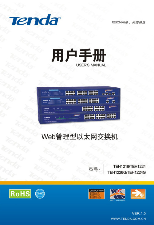
目 录第一章 产品简介 (1)1.1 产品特性 (1)1.2 物品清单 (3)第二章 硬件安装 (4)2.1 交换机前面板的说明 (4)2.2 交换机后面板的说明 (7)2.3 环境需求说明 (7)2.4 硬件安装 (8)第三章 配置指南 (10)3.1 快速登录 (10)3.2 系统信息 (12)3.3 端口管理 (13)3.3.1 端口设置 (14)3.3.2 端口带宽控制 (16)3.3.3 广播风暴控制 (17)3.3.4 端口统计信息 (18)3.4 端口镜像 (20)3.5 VLAN设置 (21)3.5.1 VLAN模式选择 (21)3.5.2 Port-Based VLAN设置 (22)3.5.3 802.1Q VLAN设置 (23)3.6 Trunk设置 (24)3.7 QoS控制 (26)3.8 MAC地址管理 (28)3.8.1 MAC地址过滤 (28)3.8.2 静态MAC地址 (29)3.9 系统设置 (30)3.9.1 密码更改 (30)3.9.2 线路诊断 (31)3.9.3 软件升级 (32)3.9.4 IP地址设置 (34)3.9.5 MAC地址老化 (35)3.9.6 DHCP客户端 (36)3.9.7 恢复出厂设置 (36)3.9.8 备份设置 (37)3.9.9 恢复设置 (38)3.9.10 退出登录 (38)附录一 在线技术支持介绍 (39)附录二 常用命令介绍 (41)附录三 TCP/IP地址设置方法(以WinXP为例)··42第一章 产品简介感谢您购买TEH1226G/TEH1224G/TEH1224/TEH1216 Web管理交换机。
其中TEH1216、TEH1224分别提供16、24个10/100M端口;TEH1224G提供24个10/100M端口,加两个10/100/1000M RJ45端口;TEH1226G提供24个10/100M端口、加两个10/100/1000M RJ45端口、两个共享的千兆SFP(Mini GBIC)光纤模块接口,支持千兆RJ45电口与千兆SFP光纤接口的自动切换功能,用户可以按照需求,灵活地将网络从100米扩展至80千米以上。
xgpon和gpon有啥区别
EPON与GPON简介什么是EPONEPON为IEEE标准,EPON采用点bai到多点结构du,无源光纤传输方式,在以太网上zhi提供多种业dao务。
目前,IP/Ethernet应用占到整个局域网通信的95%以上,EPON由于使用上述经济而高效的结构,从而成为连接接入网最终用户的一种最有效的通信方法。
10Gbps以太主干和城域环的出现也将使EPON成为未来全光网中最佳的最后一公里的解决方案。
在一个EPON中,不需任何复杂的协议,光信号就能准确地传送到最终用户,来自最终用户的数据也能被集中传送到中心网络。
在物理层,EPON使用1000BASE的以太PHY,同时在PON的传输机制上,通过新增加的MAC控制命令来控制和优化各光网络单元(ONU)与光线路终端(OLT)之间突发性数据通信和实时的TDM通信,在协议的第二层,EPON采用成熟的全双工以太技术,使用TDM,由于ONU在自己的时隙内发送数据报,因此没有碰撞,不需CDMA/CD,从而充分利用带宽。
另外,EPON通过在MAC层中实现802.1p来提供与APON/GPON类似的QoS。
什么是GPONGPON,FSAN与ITU对其进行了标准化,其技术特色是在二层采用ITU-T定义的GFP(通用成帧规程)对Ethernet、TDM、ATM等多种业务进行封装映射,能提供1.25Gbps和2.5Gbps下行速率,和155M、622M、1.25Gbps、2.5Gbps几种上行速率,并具有较强的OAM功能。
如果不考虑EPON可以看得到的不久将提升到10Gbps速率(10G以太网已经成熟),当前在高速率和支持多业务方面,GPON有优势,但技术的复杂和成本目前要高于EPON。
PON系统无疑是其中佼佼者,EPON与GPON,两种技术各有千秋,无论是EPON技术还是GPON技术,其应用在很大程度上决定于光纤接入成本的快速降低和业务需求,而价格则是最核心因素。
EPON与GPON对比EPON以兼容目前的以太网技术为目的,是802.3协议在光接入网上的延续,充分继承了以太网价格低、协议灵活、技术成熟等优势,具有广泛的市场和良好的兼容性。
以太网业务(E-Line,E-LAN,E-Tree)

EP-Tree : NO Services multiplexing at UNI. EVP-Tree: services multiplexing at UNI. Ethernet Multicast
Point to multipoint for broadcast applications (Video) Supports Service Multiplexed UNI (to deliver multiple channels)
以太网业务属性点
UNI,I-NNI,E-NNI
demarc
UNI-C UNI-N
NNI NNI
demarc
UNI-N
UNI-C
omer
Transport Transport Operator Operator
UNI-C UNI-N
Transport Transport Operator Operator Network Network
Point-to-Point • EVCs •Ethernet •Service UNI Multiplexed Ethernet UNI •CE
•* This is a UNI that must be configurable to support Multiple EVCs per UNI
•MEN
基本概念(2)
Customer Equipment (CE) attaches to the Metro Ethernet Network (MEN) at the UNI
Using standard Ethernet frames.
CE can be
xgpon和gpon有啥区别

xgpon和gpon有啥区别xgpon和gpon有啥区别EPON和GPON各有千秋,从性能指标上GPON要优于EPON,但是EPON拥有了时间和成本上的优势,GPON正在迎头赶上,展望未来的宽带接⼊市场也许并⾮谁替代谁,应该是共存互补。
对于带宽、多业务,QoS和安全性要求较⾼以及ATM技术作为⾻⼲⽹的客户,GPON会更加适合。
什么是PON?宽带接⼊技术风起云涌,注定成为⼀块硝烟永远不会散去的战场。
⽬前国内占主流仍然是ADSL技术,不过越来越多的设备⼚商及运营商已经把⽬光投向了光⽹络接⼊技术。
铜价不断攀升,光缆价格不断下降,不断增长的?IPTV,视频游戏业务对带宽的巨⼤需求推动着?FTTH?的发展。
由光缆取代铜缆及有线同轴电缆,电话,有线电视,宽带数据三⽹合⼀的美好前景变的清晰起来。
图⼀:PON拓扑结构PON(PassiveOpticalNetwork)⽆源光⽹络是实现FTTH?光纤到户的主要技术,提供点到多点的光纤接⼊,如图⼀所⽰,它由局侧的OLT(光线路终端)、⽤户侧的ONU(光⽹络单元)以及ODN(光分配⽹络)组成。
⼀般其下⾏采⽤TDM⼴播⽅式、上⾏采⽤TDMA(时分多址接⼊)⽅式,组成点到多点树形拓扑结构。
PON作为光接⼊技术最⼤的亮点是“⽆源”,ODN中不含有任何有源电⼦器件及电⼦电源,全部由光分路器(Splitter)等⽆源器件组成,管理维护运营成本较低。
PON发展史PON技术研究起源于1995年,1998年10⽉,ITU通过了FSAN?组织(全业务接⼊⽹)所倡导的基于ATM的PON技术标准——G。
983。
也被称为BPON(BroadbandPON)。
速率为155Mbps,可选择⽀持622Mbps速率。
EFMA(Ethernet intheFirstMileAlliance,第⼀英⾥以太⽹联盟)于2000年底提出了Ethernet-PON(EPON)的概念,传输速率达1Gbps,链路层基于简单的Ethernet封装。
RKS-G4028系列28G端口(带802.3bt PoE选项)全Gigabit模块管理以太网交换机
RKS-G4028Series28G-port (with 802.3bt PoE option)full Gigabit modular managed EthernetswitchesFeatures and Benefits•Meets a wide range of demands from Fast Ethernet to full Gigabit industrialnetworks (up to 28Gigabit ports)•Modular interfaces for flexible connector type combinations •Support for IEEE 802.3bt PoE for up to 90W output per port •High EMC immunity compliant with IEC 61850-3and IEEE 1613•Hardware-based IEEE 1588PTP for high-precision time synchronization •Turbo Ring and Turbo Chain (recovery time <20ms @250switches)1,andSTP/RSTP/MSTP for network redundancy•-40to 75°C operating temperature range•Supports MXstudio for easy,visualized industrial network management •Developed according to the IEC 62443-4-1and compliant with the IEC62443-4-2industrial cybersecurity standardsCertificationsIntroductionThe RKS-G4028Series is designed to meet the rigorous demands of mission-critical applications for industry and business,such as power substation automation systems (IEC 61850-3,IEEE 1613),railway applications (EN 50121-4),and factory automation systems.The RKS-G4028Series’Gigabit and Fast Ethernet backbone,redundant ring,and 24VDC,48VDC,or 110/220VDC/VAC dual isolated redundant power supplies increase the reliability of your communications and save on wiring costs.The modular design of the RKS-G4028Series also makes network planning easy,and allows greater flexibility by letting you install up to 28Gigabit ports with various connector types.Additional Features and Benefits•Layer 3switching functionality to move data and information across networks (L3models only)•IEEE 1588v2PTP (Precision Time Protocol)for network time synchronization•Command line interface (CLI)for quickly configuring major managed functions•IGMP snooping and GMRP for filtering multicast traffic•Port-based VLAN,IEEE 802.1Q VLAN,and GVRP to ease network planning•QoS (IEEE 802.1p/1Q and TOS/DiffServ)to increase determinism •IEEE 802.3ad,LACP for optimum bandwidth utilization •Line-swap fast recovery•TACACS+,IEEE 802.1X,SNMPv3,HTTPS,and SSH to enhance network security•SNMPv1/v2c/v3for different levels of network management •RMON for proactive and efficient network monitoring•Bandwidth management prevents unpredictable network status with “Lock port”to restrict access to authorized MAC addresses •Port mirroring for online debugging•Automatic warning by exception through email and relay output •Automatic recovery of connected device’s IP addresses•Configurable by web browser,Telnet/serial console,CLI,Windows utility,and ABC-02-USB automatic backup configuratorSpecificationsInput/Output InterfaceAlarm Contact Channels1relay output with current carrying capacity of 2A @24VDC1.If the port link speed is 1Gigabit or higher,the recovery time is <50ms.Ethernet Interface10/100/1000BaseT(X)Ports(RJ45connector)RKS-G4028-4GT models:4RKS-G4028-L3-4GT models:4100/1000BaseSFP Slots RKS-G4028-4GS models:4RKS-G4028-L3-4GS models:4RKS-G4028-PoE-4GS models:4RKS-G4028-L3-PoE-4GS models:4Module There are3module slots on the ers can select different types of modules toinsert into the switch.The modules that can be selected include8-port/6-port moduleswith10/100/1000BaseT(X),10/100BaseT(X),100/1000BaseSFP,or100BaseFX(SC/STconnector)interfaces.Refer to Expansion Modules in the Accessories section for a full list of supportedinterface modules.Standards IEEE802.1D-2004for Spanning Tree ProtocolIEEE802.1p for Class of ServiceIEEE802.1Q for VLAN TaggingIEEE802.1s for Multiple Spanning Tree ProtocolIEEE802.1w for Rapid Spanning Tree ProtocolIEEE802.1X for authenticationIEEE802.3for10BaseTIEEE802.3ab for1000BaseT(X)IEEE802.3ad for Port Trunk with LACPIEEE802.3u for100BaseT(X)and100BaseFXIEEE802.3x for flow controlIEEE802.3z for1000BaseSX/LX/LHX/ZXIEEE802.3bt for Power over EthernetEthernet Software FeaturesManagement IPv4/IPv6Note:IPv6is available for L2models only.Flow controlBack Pressure Flow ControlDHCP Server/ClientARPRARPLLDPLinkup DelaySMTPSNMP TrapSNMP InformSNMPv1/v2c/v3RMONTFTPSFTPHTTPHTTPSTelnetSyslogPrivate MIBFiber checkDHCP Relay Agent(Option82)Port Mirroring(SPAN,RSPAN)Filter GMRPGVRPGARP802.1QIGMP Snooping v1/v2/v3IGMP QuerierRedundancy Protocols STPRSTPTurbo Ring v2Turbo ChainRing CouplingDual-HomingMRPLink AggregationNetwork Loop ProtectionMSTPRouting Redundancy L3models:VRRPSecurity Broadcast storm protectionRate LimitAccess control listStatic port lockSticky MACHTTPS/SSLSSHRADIUSTACACS+Login and password policySecure bootMAC authentication bypassTrust access controlDynamic ARP InspectionDHCP SnoopingIP Source GuardTime Management SNTPIEEE1588v2PTP(hardware-based)Supported power profiles:IEEE1588Default2008,IEC61850-9-3-2016,IEEE C37.238-2017NTP Server/ClientNTP AuthenticationProtocols IPv4/IPv6Note:IPv6is available for L2models only.TCP/IPUDPICMPARPRARPTFTPDNSNTP ClientDHCP ServerDHCP Client802.1XQoSHTTPSHTTPEtherNet/IPModbus TCPTelnetSMTPSNMPv1/v2c/v3RMONSyslogUnicast Routing L3models:OSPF,Static RouteMIB P-BRIDGE MIBQ-BRIDGE MIBIEEE8021-SPANNING-TREE-MIBIEEE8021-PAE-MIBIEEE8023-LAG-MIBLLDP-EXT-DOT1-MIBLLDP-EXT-DOT3-MIBSNMPv2-MIBRMON MIB Groups1,2,3,9Power Substation MMS1588PTP Power Profile IEC61850-9-31588PTP Power Profile C37.238-2017Switch PropertiesIGMP Groups1024Jumbo Frame Size9.6KBMAC Table Size16KMax.No.of VLANs256Packet Buffer Size 1.5MbitsPriority Queues8VLAN ID Range VID1to4094USB InterfaceStorage Port USB Type AMicroSD InterfaceStorage Port MicroSD cardSerial InterfaceConsole Port RS-232(RJ45)Power ParametersTotal PoE Power Budget PoE models:300WMax.PoE Power Output per Port PoE models:IEEE802.3af:15.4WIEEE802.3at:30WIEEE802.3bt:90WInput Voltage RKS-G4028-LV models:24/48VDCRKS-G4028-2LV models:24/48VDC(redundant power supplies)RKS-G4028-HV models:110/220VAC,110/220VDCRKS-G4028-2HV models:110/220VAC,110/220VDC(redundant power supplies)PoE models:48VDC(for the PoE system)Operating Voltage RKS-G4028-LV/2LV models:18to72VDCRKS-G4028-HV/2HV models:88to300VDC,85to264VACPoE models:46to57VDC(for the PoE system)Overload Current Protection SupportedReverse Polarity Protection SupportedInput Current RKS-G4028-LV/2LV models:Max.2.53A@24VDCMax.1.25A@48VDCRKS-G4028-HV/2HV models:Max.0.55A@110VDCMax.0.29A@220VDCMax.1.01A@110VACMax.0.62A@220VACEPS(PoE models only):Max.7.50A@48VDCPower Consumption(Max.)RKS-G4028-LV/2LV models:Max.60.72W@24VDCMax.60W@48VDCRKS-G4028-HV/2HV models:Max.60.5W@110VDCMax.63.8W@220VDCMax.62.2W@110VACMax.64.1W@220VACNote:These are the maximum power consumption ratings for the device with themaximum number of modules installed.Physical CharacteristicsIP Rating IP30Dimensions440x44x300mm(17.32x1.37x11.81in)Weight RKS-G4028-LV/HV models:4900g(10.80lb)RKS-G4028-2LV/2HV models:5200g(11.46lb)RKS-G4028-PoE-LV/HV models:5000g(11.02lb)RKS-G4028-PoE-2LV/2HV models:5300g(11.68lb)Installation Rack mountingEnvironmental LimitsOperating Temperature-40to75°C(-40to167°F)Storage Temperature(package included)-40to85°C(-40to185°F)Ambient Relative Humidity5to95%(non-condensing)Standards and CertificationsSafety EN62368-1UL62368-1UL61010EMC EN55032/35EMI CISPR32,FCC Part15B Class ATraffic Control NEMA TS2EMS IEC61000-4-2ESD:Contact:8kV;Air:15kVIEC61000-4-3RS:80MHz to1GHz:35V/mIEC61000-4-4EFT:Power:4kV;Signal:4kVIEC61000-4-5Surge:Power:4kV;Signal:4kVIEC61000-4-6CS:10VIEC61000-4-8PFMFIEC61000-4-11DIPsPower Substation IEC61850-3IEEE1613Railway EN50121-4Freefall IEC60068-2-32Shock IEC60068-2-27Vibration IEC60068-2-6MTBFTime RKS-G4028-4GT-HV models:572,888hoursRKS-G4028-4GT-2HV models:518,894hoursRKS-G4028-4GS-HV models:529,925hoursRKS-G4028-4GS-2HV models:483,436hoursRKS-G4028-4GT-LV models:548,589hoursRKS-G4028-4GT-2LV models:479,574hoursRKS-G4028-4GS-LV models:508,639hoursRKS-G4028-4GS-2LV models:449,160hoursRKS-G4028-PoE-4GS-HV models:508,190hoursRKS-G4028-PoE-4GS-2HV models:465,282hoursRKS-G4028-PoE-4GS-LV models:488,598hoursRKS-G4028-PoE-4GS-2LV models:433,472hoursStandards Telcordia(Bellcore),GBWarrantyWarranty Period5yearsDetails See /warrantyPackage ContentsDevice1x RKS-G4028Series switchInstallation Kit2x rack-mounting ear4x protective caps for unused SFP ports(for RKS-G4028-GS models only)8x round stickers for module screwsDocumentation1x quick installation guide1x warranty cardNote 1.Only the RKS-G4028-PoE Series and RKS-G4028-L3-PoE models support PoEfunctionality with RM-G4000-8GPoE and/or RM-G4000-8PoE modules.2.Power over Ethernet requires the48VDC external power supply(46to57VDC).3.The48VDC external power supply,SFP modules,and modules from the RM-G4000Module Series need to be purchased separately for use with this product.DimensionsOrdering InformationModel Name Max.No.ofPortsPoE Support L3Functionality Input VoltageRedundantPower SuppliesExternal PowerSupplyOperatingTemp.RKS-G4028-4GT-HV-T28––110/220VAC/VDC––-40to75°CRKS-G4028-4GT-2HV-T28––110/220VAC/VDC✓–-40to75°CRKS-G4028-4GS-HV-T28––110/220VAC/VDC––-40to75°CRKS-G4028-4GS-2HV-T28––110/220VAC/VDC✓–-40to75°CRKS-G4028-4GT-LV-T28––24/48VDC––-40to75°C RKS-G4028-4GT-2LV-T28––24/48VDC✓–-40to75°C RKS-G4028-4GS-LV-T28––24/48VDC––-40to75°C RKS-G4028-4GS-2LV-T28––24/48VDC✓–-40to75°CRKS-G4028-L3-4GT-HV-T 28–✓110/220VAC/VDC––-40to75°CRKS-G4028-L3-4GT-2HV-T 28–✓110/220VAC/VDC✓–-40to75°CRKS-G4028-L3-4GS-HV-T 28–✓110/220VAC/VDC––-40to75°CRKS-G4028-L3-4GS-2HV-T 28–✓110/220VAC/VDC✓–-40to75°CRKS-G4028-L3-4GT-LV-T28–✓24/48VDC––-40to75°CRKS-G4028-L3-4GT-2LV-T28–✓24/48VDC✓–-40to75°CRKS-G4028-L3-4GS-LV-T28–✓24/48VDC––-40to75°CRKS-G4028-L3-4GS-2LV-T28–✓24/48VDC✓–-40to75°CRKS-G4028-PoE-4GS-HV-T 28✓–110/220VAC/VDC–✓-40to75°CRKS-G4028-PoE-4GS-2HV-T 28✓–110/220VAC/VDC✓✓-40to75°CRKS-G4028-PoE-4GS-LV-T28✓–24/48VDC–✓-40to75°CRKS-G4028-PoE-4GS-2LV-T28✓–24/48VDC✓✓-40to75°CRKS-G4028-L3-PoE-4GS-HV-T 28✓✓110/220VAC/VDC–✓-40to75°CRKS-G4028-L3-PoE-4GS-2HV-T 28✓✓110/220VAC/VDC✓✓-40to75°CRKS-G4028-L3-PoE-4GS-LV-T28✓✓24/48VDC–✓-40to75°CRKS-G4028-L3-PoE-4GS-2LV-T28✓✓24/48VDC✓✓-40to75°C Accessories(sold separately)Expansion ModulesRM-G4000-8TX Fast Ethernet module with810/100BaseT(X)portsRM-G4000-8SFP Fast Ethernet module with8100BaseSFP slotsRM-G4000-8PoE Fast Ethernet module with810/100BaseT(X)IEEE802.3bt PoE portsRM-G4000-8GTX Gigabit Ethernet module with810/100/1000BaseT(X)portsRM-G4000-8GSFP Gigabit Ethernet module with8100/1000BaseSFP slotsRM-G4000-8GPoE Gigabit Ethernet module with810/100/1000BaseT(X)IEEE802.3bt PoE portsRM-G4000-6MSC Fast Ethernet module with6multi-mode100BaseFX ports with SC connectorsRM-G4000-6MST Fast Ethernet module with6multi-mode100BaseFX ports with ST connectorsRM-G4000-6SSC Fast Ethernet module with6single-mode100BaseFX ports with SC connectorsRM-G4000-4MSC2TX Fast Ethernet module with4multi-mode100BaseFX ports with SC connectors,210/100BaseT(X)portsRM-G4000-4MST2TX Fast Ethernet module with4multi-mode100BaseFX ports with ST connectors,210/100BaseT(X)portsRM-G4000-4SSC2TX Fast Ethernet module with4single-mode100BaseFX ports with SC connectors,210/100BaseT(X)portsRM-G4000-2MSC4TX Fast Ethernet module with2multi-mode100BaseFX ports with SC connectors,410/100BaseT(X)portsRM-G4000-2MST4TX Fast Ethernet module with2multi-mode100BaseFX ports with ST connectors,410/100BaseT(X)portsRM-G4000-2SSC4TX Fast Ethernet module with2single-mode100BaseFX ports with SC connectors,410/100BaseT(X)portsStorage KitsABC-02-USB Configuration backup and restoration tool,firmware upgrade,and log file storage tool for managedEthernet switches and routers,0to60°C operating temperatureABC-02-USB-T Configuration backup and restoration tool,firmware upgrade,and log file storage tool for managedEthernet switches and routers,-40to75°C operating temperatureABC-03-microSD-T MicroSD-based configuration backup and restoration tool,firmware upgrades,and log file storage toolfor managed Ethernet switches and WLAN products,-40to85°C operating temperatureSFP ModulesSFP-1FELLC-T SFP module with1100Base single-mode with LC connector for80km transmission,-40to85°Coperating temperatureSFP-1FEMLC-T SFP module with1100Base multi-mode,LC connector for2/4km transmission,-40to85°C operatingtemperatureSFP-1FESLC-T SFP module with1100Base single-mode with LC connector for40km transmission,-40to85°Coperating temperatureSFP-1G10ALC WDM-type(BiDi)SFP module with11000BaseSFP port with LC connector for10km transmission;TX1310nm,RX1550nm,0to60°C operating temperatureSFP-1G10BLC WDM-type(BiDi)SFP module with11000BaseSFP port with LC connector for10km transmission;TX1550nm,RX1310nm,0to60°C operating temperatureSFP-1G20ALC WDM-type(BiDi)SFP module with11000BaseSFP port with LC connector for20km transmission;TX1310nm,RX1550nm,0to60°C operating temperatureSFP-1G20BLC WDM-type(BiDi)SFP module with11000BaseSFP port with LC connector for20km transmission;TX1550nm,RX1310nm,0to60°C operating temperatureSFP-1G40ALC WDM-type(BiDi)SFP module with11000BaseSFP port with LC connector for40km transmission;TX1310nm,RX1550nm,0to60°C operating temperatureSFP-1G40BLC WDM-type(BiDi)SFP module with11000BaseSFP port with LC connector for40km transmission;TX1550nm,RX1310nm,0to60°C operating temperatureSFP-1G10ALC-T WDM-type(BiDi)SFP module with11000BaseSFP port with LC connector for10km transmission;TX1310nm,RX1550nm,-40to85°C operating temperatureSFP-1G10BLC-T WDM-type(BiDi)SFP module with11000BaseSFP port with LC connector for10km transmission;TX1550nm,RX1310nm,-40to85°C operating temperatureSFP-1G20ALC-T WDM-type(BiDi)SFP module with11000BaseSFP port with LC connector for20km transmission;TX1310nm,RX1550nm,-40to85°C operating temperatureSFP-1G20BLC-T WDM-type(BiDi)SFP module with11000BaseSFP port with LC connector for20km transmission;TX1550nm,RX1310nm,-40to85°C operating temperatureSFP-1G40ALC-T WDM-type(BiDi)SFP module with11000BaseSFP port with LC connector for40km transmission;TX1310nm,RX1550nm,-40to85°C operating temperatureSFP-1G40BLC-T WDM-type(BiDi)SFP module with11000BaseSFP port with LC connector for40km transmission;TX1550nm,RX1310nm,-40to85°C operating temperatureSFP-1GEZXLC SFP module with11000BaseEZX port with LC connector for110km transmission,0to60°C operatingtemperatureSFP-1GEZXLC-120SFP module with11000BaseEZX port with LC connector for120km transmission,0to60°C operatingtemperatureSFP-1GLHLC SFP module with11000BaseLH port with LC connector for30km transmission,0to60°C operatingtemperatureSFP-1GLHXLC SFP module with11000BaseLHX port with LC connector for40km transmission,0to60°C operatingtemperatureSFP-1GLSXLC SFP module with11000BaseLSX port with LC connector for1km/2km transmission,0to60°Coperating temperatureSFP-1GLXLC SFP module with11000BaseLX port with LC connector for10km transmission,0to60°C operatingtemperatureSFP-1GSXLC SFP module with11000BaseSX port with LC connector for300m/550m transmission,0to60°Coperating temperatureSFP-1GZXLC SFP module with11000BaseZX port with LC connector for80km transmission,0to60°C operatingtemperatureSFP-1GLHLC-T SFP module with11000BaseLH port with LC connector for30km transmission,-40to85°C operatingtemperatureSFP-1GLHXLC-T SFP module with11000BaseLHX port with LC connector for40km transmission,-40to85°Coperating temperatureSFP-1GLSXLC-T SFP module with11000BaseLSX port with LC connector for1km/2km transmission,-40to85°Coperating temperatureSFP-1GLXLC-T SFP module with11000BaseLX port with LC connector for10km transmission,-40to85°C operatingtemperatureSFP-1GSXLC-T SFP module with11000BaseSX port with LC connector for300m/550m transmission,-40to85°Coperating temperatureSFP-1GZXLC-T SFP module with11000BaseZX port with LC connector for80km transmission,-40to85°C operatingtemperatureSFP-1GTXRJ45-T SFP module with11000BaseT port with RJ45connector for100m transmission,-40to75°C operatingtemperatureSoftwareMXview-100MXview license for100nodesMXview-50MXview license for50nodesMXview-250MXview license for250nodesMXview-500MXview license for500nodesMXview-1000MXview license for1000nodesMXview-2000MXview license for2000nodesMXview Upgrade-50MXview license expansion for50nodes©Moxa Inc.All rights reserved.Updated June14,2023.This document and any portion thereof may not be reproduced or used in any manner whatsoever without the express written permission of Moxa Inc.Product specifications subject to change without notice.Visit our website for the most up-to-date product information.。
GPON技术资料

1 中兴GPON系统性能和结构1.1 概述GPON技术是基于ITU-T G.984.x标准的新一代宽带无源光综合接入技术,支持多种速率等级,支持上下行不对称速率,下行可提供 1.25Gbps或2.5Gbps, 上行可提供155Mbps/622Mbps/1.25Gbps或2.5Gbps等速率;同时GPON具备完善的DBA和QOS全业务保障能力,更加适合于全业务的承载接入。
为了满足运营商对GPON新技术的发展需求,满足高带宽、高效率、多业务、QOS、安全性等用户需求,降低网络的CAPEX和OPEX,中兴通讯公司基于对网络发展内在规律的深入把握,推出了ZXA10 GPON无源光网络系列设备,为接入网的网络建设以及业务提升提供了坚实的技术和业务平台。
ZXA10 GPON包括ZXA10 C220局端设备,以及F系列用户端设备、MDU和MTU多用户接入单元等。
1.2 ZXA10 GPON 系统特点中兴通讯可全面提供基于包括局端设备C220,用户端在内的GPON解决方案。
在1:64的分光比下,单系统提供2560 ONT的接入,同时可实现相应的保护。
用户端设备可以提供10/100M、10/100/1000M、xDSL、WLAN、E1/T1、POTS、RF等各种接入方式。
中兴通讯提供基于GPON/ EPON技术同平台的C220设备,平台支持GPON/EPON单板混插,因此组网将更加灵活。
ZXA10 GPON系统特点如下:∙支持话音业务、数据业务和视频业务三网合一的Triple-Play业务的开展,话音业务以VoIP方式提供,数据业务提供大带宽的上下行数据业务流量的能力,视频业务支持基于IP数据的VOD/IPTV和基于第三波长CATV两种方式;∙大容量,高集成度。
ZXA10 C220系统采用全GE总线,上行线卡基于10GE总线,提供1.12 Tbit/s的背板总线带宽与320Gbit/s的交换能力,满足线性无阻塞交换要求;同时单系统最大支持2560个ONU接入,满足大规模FTTx业务开展要求;∙完善组播业务支持与强大的可控组播能力。
MSTP四种业务类型

1 华为OptiX系列产品以太网组网应用关键字EPL EVPL EPLAN EVPLAN内容摘要随着Internet的高速发展,各种宽带接入和应用逐渐兴起,同时越来越多的新兴公司办公地点开始多元化,需要进行高速互连,而原有的窄带数据通信已经不能满足需求。
在这种情况下,MSTP(多业务传送平台)技术就应运而生了,它可以对多种类型的以太网业务在SDH平台进行处理和传送。
本部分主要了介绍了EPL、EVPL、EPLAN和EVPLAN以太网业务类型和组网应用的相关知识,并通过实际组网举例,主要帮助光网络维护人员更好的理解和掌握各种以太网业务的类型、组网应用以及各种组网间的差别,从而更好的维护MSTP网络。
1.1 概述华为公司的MSTP设备遵循ITU-T G.etnsrv的建议,可支持以下四种以太网业务类型:●以太网专线:EPL(Ethernet Private Line)●以太网虚拟专线:EVPL(Ethernet Virtual Private Line)●以太网私有局域网:EPLAN(Ethernet Private LAN)●以太网虚拟私有局域网:EVPLAN(Ethernet Virtual Private LAN)EPL(Ethernet Private Line)以太网私有专线:以太网透传业务,各个用户独占一个VCTRUNK带宽,业务延迟低,提供用户数据的安全性和私有性。
EVPL(Ethernet Virtual Private Line)以太网私有专线:又可称为VPN专线,其优点在于不同业务流可共享VC TRUNK通道,使得同一物理端口可提供多条点到点的业务连接,并在各个方向上的性能相同,接入带宽可调、可管理,业务可收敛实现汇聚,节省端口资源。
EPLAN( Ethernet Private LAN )以太网私有局域网:也称为二层(L2)交换业务,实现多点到多点的业务连接。
接入带宽可调,可管理,业务可收敛、汇聚。
100G以太网技术概述

二 、o G 以太 网技 术 lo
10 0 G以太 网从研究 到商 用 , 需要 解决好 接 口、 输 、 传
封装 、 关键 器件 等 四 方 面 的关 键 技 术 。 目前 10 以 太 网 0G 图 1 IE 0 .h 理 层 体 系 结构 图 E E82 3 a物
P MD子层根据带宽 、 距离 和使 用范 围的不 同 , 制定了
中 图分 类 号 :P 9 .3 T 33 0 文献标识码 : A 文 章 编 号 :0 8— 27 2 1 )5— 0 1 0 10 4 0 (0 0 0 0 6 — 4
一
、
问题 的提 出
82 3 a标准 带宽应该 为 10 b s 但高 速 以太 网小组 委 0.b 0 G/ ,
随着视频 、2 P P等宽带密集应 用及远程存储 、 虚拟 化 、 云计算 等企业 核心应 用 的发展 , 1G传输技 术为基 础 以 0
IE 8 2 3 a 准 中物 理 层 主要 包 括 P S 物 理 媒 E E P0 . b 标 C、
介附加 子层 ( MA) 物 理媒介 相关子 层 ( MD) P 、 P 。物理层 规范要求保持 8 2 3以太 网 M C层 帧格式 和大小 不变 , 0. A
用传输 , 可利用成熟的 1 G以太网器件 , 0 但并行 多模封装
6 2
王 小 军 :O G以太 网技 术 概 述 IO
术和串并行转换技术各厂商产 品间的标准还不兼容 , 没 还
有成 熟 通 用 的模 块 产 品 。
10 0 G反 向 复 用 到 1 G、 0 0 4x1 G或 1 0 复 用 到 10 0x1 G 0G
高速串 口并映射 到 10 T 0 G O N进行 传输 。IU TS 1 T — G 5会 议决 定 将 10 E映 射 到 O U 0G D 4适 配 到 O U 速 率 为 T 4, 1 18993 而放弃原来 的 O U 6 G方案 , 1.0 7 G, T 4 10 这样 可更
xgpon和gpon有啥区别
EPON与GPON简介什么是EPONEPON是IEEE标准。
EPON采用点对多点结构和无源光纤传输方式,在以太网中提供各种业务。
IP/以太网应用目前占局域网通信的95%以上,而EPON由于其经济高效的体系结构,是连接接入网终端用户最有效的通信方式之一。
10Gbps以太网主干网和城市环路的出现也将使EPON成为未来全光网络的最佳最后一公里解决方案。
在一个EPON中,不需任何复杂的协议,光信号就能准确地传送到最终用户,来自最终用户的数据也能被集中传送到中心网络。
在物理层,EPON使用1000BASE的以太PHY,同时在PON的传输机制上,通过新增加的MAC控制命令来控制和优化各光网络单元(ONU)与光线路终端(OLT)之间突发性数据通信和实时的TDM通信,在协议的第二层,EPON采用成熟的全双工以太技术,使用TDM,由于ONU在自己的时隙内发送数据报,因此没有碰撞,不需CDMA/CD,从而充分利用带宽。
另外,EPON通过在MAC层中实现802.1p来提供与APON/GPON类似的QoS。
什么是GPONGPON,FSAN与ITU对其进行了标准化,其技术特色是在二层采用ITU-T定义的GFP(通用成帧规程)对Ethernet、TDM、ATM等多种业务进行封装映射,能提供1.25Gbps和2.5Gbps下行速率,和155M、622M、1.25Gbps、2.5Gbps几种上行速率,并具有较强的OAM功能。
如果不考虑EPON可以看得到的不久将提升到10Gbps 速率(10G以太网已经成熟),当前在高速率和支持多业务方面,GPON有优势,但技术的复杂和成本目前要高于EPON。
PON系统无疑是其中佼佼者,EPON与GPON,两种技术各有千秋,无论是EPON技术还是GPON技术,其应用在很大程度上决定于光纤接入成本的快速降低和业务需求,而价格则是最核心因素。
EPON与GPON对比EPON以兼容目前的以太网技术为目的,是802.3协议在光接入网上的延续,充分继承了以太网价格低、协议灵活、技术成熟等优势,具有广泛的市场和良好的兼容性。
- 1、下载文档前请自行甄别文档内容的完整性,平台不提供额外的编辑、内容补充、找答案等附加服务。
- 2、"仅部分预览"的文档,不可在线预览部分如存在完整性等问题,可反馈申请退款(可完整预览的文档不适用该条件!)。
- 3、如文档侵犯您的权益,请联系客服反馈,我们会尽快为您处理(人工客服工作时间:9:00-18:30)。
外部端口和内部端口
以太网单板的外部端口用于提供用户侧业务的接入,内部端口用于将业务封装映射到传输网络侧进行透明传输。
以太网单板的外部端口即外部物理接口,也称为客户侧接口或者用户侧接口,用于接入用户侧的以太网业务。
以太网单板的内部端口端口即内部VCTRUNK(Virtual Container Trunk)接口,在某些应用场合亦称为系统侧接口或背板侧接口,用于将业务封装映射到SDH侧。
VCTRUNK是通过VC容器实现的传送通道,可以用相邻级联技术实现,也可以用虚级联技术实现。
在网管界面上,通过绑定通道来为VCTRUNK端口指定不同颗粒度的带宽。
图1 以太网单板的外部和内部端口
TAG属性
数据帧进入或离开以太网单板的端口时,端口的TAG属性将影响端口对数据帧的处理方式。
以太网单板端口的Tag标识分Tag Aware、Access和Hybrid三种。
表1 各种TAG标识的端口对数据帧的处理方法
方
向
数据帧类型处理方式
Tag
aware
Access Hybird
入端口携带VLAN标签
的帧
透传丢弃透传
没有携带VLAN
标签的帧
丢弃添加包含“缺省VLAN ID”和“VLAN优先级”的VLAN标签后
透传。
出端口
携带VLAN标签
的帧
透传剥离VLAN
标签后发送
•如果数据帧中的VLAN ID是“缺省
VLAN ID”,剥离VLAN标签后发送。
•如果数据帧中的VLAN ID不是“缺省
VLAN ID”,透传。
说明:
只有满足以下2个条件时,设置TAG标识才有意义。
•端口属性值为PE或UNI。
•已使能入口检测。
当以太网交换单板工作在以太网透传状态时,因为禁止了入口检测,所以无论进入端口的数据帧是否携带VLAN标签,端口都将透明传输。
根据Tag Aware、Access和Hybrid的特点,我们可以确定端口TAG标识的设置原则。
•如果确定对接设备发出的数据包一定带有VLAN Tag,则可以设置为Tag Aware。
•如果确定对接设备发出的数据包一定不带有VLAN Tag,则可以设置为Access模式。
•如果不确定对接设备发出的数据包是否带有VLAN Tag,则可以设置为Hybrid模式。
网桥
网桥是指实现两个或更多LAN互连的功能单元。
VB和LP
VB(Various Bridge)即多样化网桥,是华为公司独创的概念。
对于具有二层交换处理能力的以太网单板,可将其交换域分割成多个相互独立的子交换域,在没有业务连通的情况下,不同的VB不能互相访问。
各个VB具有独立的配置模式,并独立使用VLAN,不同VB的VLAN可以相同。
LP(Logic Port)是逻辑端口,一个VB包含若干个LP。
通过配置挂接关系,我们可以把多个外部端口和VCTRUNK端口挂接到同一个VB上。
VB、LP、外部端口以及VCTRUNK端口之间的关系如图1所示。
图1 VB、LP、外部端口和VCTRUNK端口之间的关系
透明网桥和虚拟网桥
•多个透明网桥的业务是相互隔离的,但同一透明网桥内的业务没有隔离,整个透明网桥就是一个交换域。
•多个虚拟网桥的业务是相互隔离的,并且同一虚拟网桥内不同VLAN ID的业务也是相互隔离的,整个虚拟网桥的交换域根据不同的VLAN ID划分为多个子交换域。
说明:
如图2所示,同一个逻辑端口可以属于一个或者多个VLAN ID不同的子交换域,在网管配置界面下,也就是同一个逻辑端口可以属于不同VLAN ID的过滤表。
图 2 透明网桥和虚拟网桥。
