2015年版卡特320BC油门电机安装说明书
卡特挖掘机配件-320D中文版注释

• M2.4CB2 –
–
15.2
卡特彼勒与小松配件提供商
1,000
9
–
320D
卡特彼勒与小松配件提供商
•
(HD) –
•
–
–
•
–
(GET)
•
–
•
(GP) –
•
•
•
–
320D
•
(X)
,
•
(XSP) –
•
–
.
320D +–
– 320D
10
–
(2x)
–
––
–
–
–
–
–
–
–
–
–
–
B1
–
B1
–
CB2
–
CB2
–
205 L/min 35 000 kPa 36 000 kPa 35 000 kPa 24 500 kPa 32.4 L/min 3900 kPa 120 mm 1260 mm 140 mm 140 mm 1504 mm 1504 mm 120 mm 1104 mm 135 mm 1156 mm
中国KMP服务中心 400-888-1839 QQ:1723205377 联系人:张小姐
KMP是卡特彼勒(CATERPILLAR)与小松(KOMATSU) 发动机配件售后市场的第一国际品牌
KMP产品所面对的车型及发动机范围
KOMATSU(小松) 小松车型: D20,D30,40,D50,D60,D65,D68, D70,D75,D80,D85,D155-1/2/3,D275-1/2/3,D375-1/2/3/5. PC60,PC70,PC75,PC100,PC120,PC130,PC150,PC200-5/6/7/8,PC2205/6/7/8 ,PC300-5/6/7.PC4003/5/6/7,PC450-6,PC600-1/3/5,PC650-1/3/5/6.PC700-1/3/5,PC1000-1/2/3/4,PC1200-1/2/3/4/5/6. WA380-1/3/5,WA400-1/5,WA420,WA430,WA450,WA470,WA500-1/3/5,WA600-1/3/5,WA700-1/3/5 小松发动机: NH220NT855 - NTA8554D95L -SA6D95L,S4D102 -SA6D102,4D105 - S6D105,S6D108SA6D108,S6D110- SA6D110,S6D114 - SA6D114,6D125 -SA6D125,4D130 - S4D130,6D140 SA6D140,6D155 - SA6D155,S6D170- SA6D170,SA8V170 - SA12V17.
AO Smith ECM电动机安装及操作指南说明书
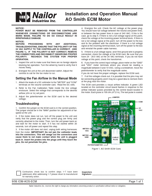
9/06 IOM-AOS-ECM Installation and Operation Manual AO Smith ECM MotorNailor Industries Inc. reserves the right to change any information concerning product or specification without notice or obligation.Page 1 of 1NOTICE:POWER MUST BE REMOVED FROM THE CONTROLLER WHENEVER CONNECTIONS OR DISCONNECTIONS ARE BEING MADE. FAILURE TO DO SO COULD RESULT IN IRREPARABLE DAMAGE.NOTICE:BEFORE PROCEEDING WITH ANY ADDITIONAL TROUBLESHOOTING, ENSURE THAT THE POLARITY OF THE 24 VAC SUPPLY TO THE CONTROLLER IS CORRECT. (SEE FIGURE 1). IF THE POLARITY IS NOT CORRECT, REMOVE THE CONNECTORS AND RECONNECT OBSERVING PROPER POLARITY. RECHECK THE SYSTEM FOR PROPER OPERATION.1.Inspect the unit to make sure that there are no foreign objectsblocking fan operation. Turn the wheel by hand to verify that it moves freely.2.Energize the unit at the unit disconnect switch. Adjust thecontrols to call for the fan motor to run.Setting the Fan Airflow in the Manual Mode 1.Attach the leads of a DC voltmeter to the "METER"and "COM"terminals on the volume controller card. Read the DC volts.2.Refer to the Fan Calibration Table inside the line voltageenclosure. Select the voltage that corresponds to the desired airflow (cfm or l/s) set point.3.Adjust the potentiometer on the ECM card to the desiredvoltage.Troubleshooting1.Confirm the jumper on the ECM card is in the correct position. The jumper should be in the "MAN"position for adjustment of fan speed at the unit.2.If the motor does not run, turn off the power to the unit and verify that the power plug and the control plug are firmly and correctly attached to the motor. Then, turn the unit power back on and wait for the motor to start. If it has not started within 20 seconds, turn off power and repeat this step.3.If the motor still does not start, unplug both wiring harnesses from the motor. IMPORTANT: Do not jam the voltmeter leads into the connectors. This will swage out the connectors and cause them to not make contact when the unit is plugged back in.Insert the probes into the plugs until they touch the pins. Do not penetrate the pins.4.Energize the unit. Check the AC voltage at the power plug. You should have full voltage between the neutral and power lines, or between the two power lines in case of 240 VAC. If this is the case, go to step5. If there is not a full voltage signal at this point, check the voltage at the incoming power terminal block. If there is not a full voltage signal at this point, turn off the power to the box and fix the problem with the electrician. If there is a full voltage signal at the incoming terminal block, turn off the power to the box and reinstall the power cable harness.5.If there is a full voltage signal, and if the ground wire is properly connected, check the voltage at the ECM card. Be sure that you have 24 - 28.5 VAC at the 24 VAC terminals. If you do not have voltage at this point, check the transformer.6.If you have the correct input voltage, place meter on the "GND" and "VDC" meter terminals where you should be reading a magnitude between 0 and 10 VDC. Using a screwdriver, move the potentiometer to verify that the magnitude varies.If you do not have the proper voltages, replace the ECM card. 7.If all the voltages check out, it is possible that the pins may not be connecting properly and it may be a good idea to recheck them at the plug near the motor.The ECM card provides a visual airflow indicator. A green LED located on the controller circuit board flashes in response to the airflow indicator pulses provided by the control board located in the motor. Each pulse is 100 cfm (47.2 l/s). The last pulse is scaled.Figure 1. AO Smith ECM Card.Contractors check box to confirm steps 1–7 have been addressed. After addressing 1–7 please return to manufacturerfor warranty action.InspectorsSignature:–––––––––––––––––––––––––––––––––––––––––CABLEPLUGMETERGNDPOTENTIOMETER。
BCLH-15铵油车说明书

BCLH—15型粒状铵油炸药车(2008.12.26准格尔车)注意——当气温低于0℃时,非工作时间装药车应存放于库房内保温;——夏季与冬季应使用不同型号的抗磨液压油。
——冬季时更换冬季柴油;——工作50小时后,更换液压油和滤芯。
——每次工作完毕,应将螺杆泵输药胶管清洗干净。
——整车安全使用年限为8年——螺杆泵安全使用年限为5年目录前言 (4)1、装药车的特点概述 (5)2、BCLH车适应范围 (6)3、型号的表示方法 (6)4、主要技术参数 (7)5、工作原理 (7)6、主要结构介绍 (8)6.1、汽车底盘 (8)6.2、动力输出系统 (9)6.3、液压系统 (13)6.4、燃油系统 (21)6.5、干料输出系统 (24)6.6、干料柴油混制系统 (24)6.7、电器控制系统 (28)7、操作与使用 (28)7.1、定员 (28)7.2、开车前的准备工作 (28)7.3、空车调试标定 (31)7.4、标定 (31)7.5、试做炸药 (34)7.6、爆区作业 (34)8、维护保养 (35)8.1、洗车 (35)8.2、汽车的维护与保养 (35)8.3、取力器的维护与保养 (35)8.4、液压系统的维护与保养 (35)8.5、爆区作业 (40)9、故障与排除 (41)10、易损件明细表 (43)11、随车工具明细表 (43)12、轴承及其它明细表 (44)13、电器、液压元件建议储备明细表 (44)14、电器操作说明 (45)前言山西惠丰特种汽车有限公司(原山西特种汽车制造厂)是国防科学技术工业委员长会批准生产现场混装炸药车及其辅助设施的专业生产企业。
现场混装炸药车是山西惠丰特种汽车有限公司引进美国埃列克化学工业公司全套技术生产,在引进的基础上不断创新,现已发展为三大系列十五个品种。
这三大系列是:L系列(即BCLH系列)该系列现场混装炸药车可现场混制粒状铵油炸药,这种炸药价格低谦,是无水炮孔理想的装药设备。
ATV320_安装手册_CN_NVE41294_01
18
尺寸与重量. . . . . . . . . . . . . . . . . . . . . . . . . . . . . . . . . . . . . . . . . . . . . . . . . . . . . . . . . . . . . . .
19
变频器额定值 . . . . . . . . . . . . . . . . . . . . . . . . . . . . . . . . . . . . . . . . . . . . . . . . . . . . . . . . . . . . .
40
线缆长度说明 . . . . . . . . . . . . . . . . . . . . . . . . . . . . . . . . . . . . . . . . . . . . . . . . . . . . . . . . . . . . .
42
接线图 . . . . . . . . . . . . . . . . . . . . . . . . . . . . . . . . . . . . . . . . . . . . . . . . . . . . . . . . . . . . . . . . . .
43
漏型 / 源型开关配置 . . . . . . . . . . . . . . . . . . . . . . . . . . . . . . . . . . . . . . . . . . . . . . . . . . . . . . . .
47
电源接线端子的特性 . . . . . . . . . . . . . . . . . . . . . . . . . . . . . . . . . . . . . . . . . . . . . . . . . . . . . . .
凯马CCFJ系列船用柴油发电机组安装使用及维护说明书概要

CCFJ系列船用柴油发电机组安装使用及维护说明书CCFJ series Marine Diesel Engine Generator Units Installation Usage and Maintenance Manual南昌凯马柴油机有限公司NanChang Kama Diesel Engine Co., Ltd.安全告示Safety Warning使用及安装CCFJ系列柴油发电机组前,请详细阅读本说明书、以及柴油机、发电机、附件的说明书(或手册),以了解机组、发电机、柴油机和有关设备的情况。
Before operating and installing CCFJ series Diesel Engine Generator Units, Please carefully read the Notebook, and Diesel Engine, Generator, Accessories’s notebook (or manual) to know the condition of Engine, Generator, Diesel Engine and related equipments.请记住安全第一,当你不甚明白所作的说明或操作程序时,应向专业人员请教后再进行正确操作和保养设备才能达到安全、有效的运行。
Pls remember safety first. If you are not sure of the instructions or procedures contained herein, seek qualified help before continuing.·确保安装能满足所有适用的安全标准和地方性电气标准。
所有安装要有合格的电工和机械工来实施。
Ensure installing can meet all available safety standard and local electric standard. All installation should be attempted by qualified electrician and machinist.·确保使用能正常、安全,必须具有电气、机械安全知识的合格的操作人员来操作使用。
卡特320C保险丝说明书
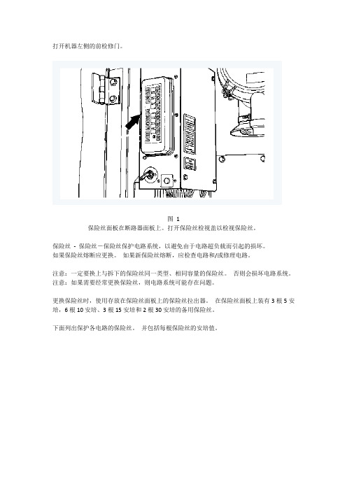
打开机器左侧的前检修门。
图1保险丝面板在断路器面板上。
打开保险丝检视盖以检视保险丝。
保险丝-保险丝-保险丝保护电路系统,以避免由于电路超负载而引起的损坏。
如果保险丝熔断应更换。
如果新保险丝熔断,应检查电路和/或修理电路。
注意:一定要换上与拆下的保险丝同一类型、相同容量的保险丝。
否则会损坏电路系统。
注意:如果需要经常更换保险丝,则电路系统可能存在问题。
更换保险丝时,使用存放在保险丝面板上的保险丝拉出器。
在保险丝面板上装有3根5安培,6根10安培、3根15安培和2根30安培的备用保险丝。
下面列出保护各电路的保险丝。
并包括每根保险丝的安培值。
图2 (1) 备用件- 5 Amp(2) 备用件- 10 Amp(3) 备用件- 10 Amp(4) 备用件- 15 Amp(5) 备用件- 15 Amp(6) 备用件- 30 Amp(7) 加热器或空调器风扇(如有配备)- 15 Amp(8) 计时器继电器- 10 Amp(9) 喇叭- 10 Amp(10) 驾驶室灯(如有配备) - 10 Amp(11) 驾驶室棚顶灯和收音机记忆装置- 10 Amp(12) 发动机起动开关- 10 Amp(13) 发动机控制器或泵控制器- 10 Amp(14) 动臂灯- 10 Amp(15) 选装部件阀控制装置(如有配备) - 15 Amp(16) 备用件- 15 Amp(17) 备用件- 5 Amp(18) 电动加燃油泵(如有配备) - 30 Amp(19) 空调器(如有配备)或驾驶室加热器- 15 Amp(20) 收音机(如有配备)和开关板- 5 Amp(21) 窗户清洗器和雨刷- 10 Amp(22) 下部窗户清洗器(如有配备)和下部窗户雨刷(如有配备) - 10 Amp(23) 备用开关和监测器控制器- 5 Amp(24) 点烟器- 10 Amp(25) 底盘灯- 10 Amp(26) 座椅加热器(如有配备) - 5 Amp(27) 12伏7安培转换器1 - 10 Amp(28) 12 伏7安培转换器2 - 10 Amp(29) 选装部件电磁线圈- 10 Amp(30) 快速连接器(如有配备) - 5 Amp(31) 电动窗(如有配备) - 15 Amp(32) 交流发电机调节器- 5 Amp(33) 驾驶室风扇(如有配备) - 5 Amp(34) 辅助回路(选装部件) - 10 Amp(35) 备用件- 5 Amp(36) 备用件- 10 Amp(37) 备用件- 10 Amp(38) 备用件- 15 Amp。
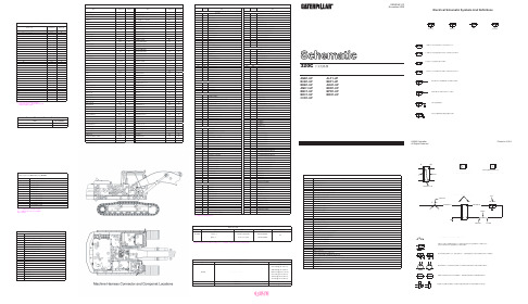
卡特 CAT320C-中文电路图
附加电力续 收音机转换器 座椅加热器
刮水器电机 刮水器电机 刮水器电机启动 刮水器电机停止 车窗限位开关接刮水器控制器 刮水器限位开关接刮水器控制 刮水器开关接刮水器控制 安全电磁阀继电器接电磁阀
空调光敏传感器信号 空调光敏传感器信号 左后扬声器 左后扬声器共用 附加插座 空调离合器电磁阀 照明电路 前工作灯 驾驶室强光灯翻车保护架 动臂工作灯 动臂工作灯继电器 底盘灯继电器 驾驶室灯继电器 底盘灯继电器 控制电路 功率控制开关 附加快速连接器 发动机转速 发动机冷却液温度和预热温度传感器信号 气门开关 气门开关 气门开关 气门开关 泵电子控制气门接地 泵电子控制发动机转速接地 泵控制阀 泵控制阀 泵电子控制旁流开关 调速器加速 调速器减速 启动控制继电器 行走模式开关 调速器指令备用开关 流量限压减压阀 初级反向控制电路压力减压阀 减压阀回油 直线行走电磁阀 行走警告解除开关
注表中所示接头都是线束对线束的接头。 线束与部件的接头一般都在部件位置上或 其附近参见部件位置表。
示意图位置
D-12 J-11 G-9 G-9 G-8 G-8 G-8 E-7 G-7 H-7 J-6 D-6 C-6 A-5 F-5 F-5 H-5 F-4 A-3 A-3 B-3 B-3 H-3 H-3 J-2 H-2 H-2 F-2 C-2 C-2 F-1 F-1 G-1 J-2
200 201 210 229 235
304 306 307 308 309 310 320 321 322 323 325 326 329 330 365
403 405 410 412 430 487 491 492 495 496 C468 E469 E470 E471 E472 E473 E474 E475 E476 H465 H466 H467 H473 H474 H475 H476
卡特320B电脑数据调整方法
卡特320B电脑数据调整方法卡特320B电脑数据调整方法CAT挖掘机B系列电脑存储器数据库调用方法:1,同时按住警报停止开关和使用者模式开关2秒,可以打开存储器2,用动背优先和回转优先来增减数值..用微调调模式和使用者模式来左右移动调整位置密码OE 32 3A1301 机油压力过低1302 水温过高1303液压油温过高1304 空气内芯堵塞1305电瓶电压不正常(过高或过低) 2201油门马达有断路或对电瓶短路2202调速器油门马达反馈电路对地短路2301调速器油门马达反馈信号不稳定2302调速器油门马达反馈信号不正常2303调速器油门马达不工作2304校正数据错误3201监测器RAM失常4101电脑输入电压超过43V 4102比例减压阀内电流过大4103比例减压阀电路断开4105挖沟电磁阀的电流过大4106 微控电磁阀的电流过大4107行走变速电磁阀的电流过大4108行走警告电流过大410A回转制动电磁阀的电流过大4201发动机转速异常4202水温传感器线路对地短路4203液压油温传感器线路接地短路4204油泵出口压力PWM传感器接地短路4207油泵出口压力PWM型传感器电路断开420A燃油位置传感器接地短路420B燃油位置传感器线路断开或对电瓶短路420C电瓶电压过低420D电压过高420E发动机转速不足(速度旋纽异常)4301发动机和转速传感器有误配4302转速传感器线路短路或损坏4303******停止转动A201 监控器通讯不正常A202监控器对电脑信号反应太慢A203 控制器通信异常分享]卡特320B/BL挖掘机电脑调整资料按22再按25+26,2秒后显示00 00 00。
按25使显示位右移,26使显示位左移,23使显示位加,24使显示位减直到输入密码0E323A,10秒以后电脑自动进入服务程序且左位首先显示10,右则显示(1),同带通过23,24,25,26可以改变服务显示码。
卡特320D 320DL挖掘机产品说明

2
Structures
Caterpillar® design and manufacturing techniques assure outstanding durability and service life from these important components. pg. 8
Booms, Sticks and Bucket Linkages
Work Tools – Attachments
Three lengths of booms and five sticks are available, offering a range of configurations suitable for a wide variety of application conditions. The bucket linkage pins have been enlarged to improve reliability and durability. All Booms and Sticks are stress relieved. pg. 9
Cat C6.4. The Cat C6.4 with ACERT™ Technology introduces a series of evolutionary, incremental improvements that provide breakthrough engine technology. The building blocks of ACERT Technology are fuel delivery, air management and electronic control. ACERT Technology optimizes engine performance while meeting global low emission regulations. With its proven technology, robust components and precision manufacturing, you can count on this engine to power up at start time and keep working productively all shift long.
CAT320说明书

320D/320D L®液压挖掘机依靠卡特彼勒和其广泛的代理商网络,我们可为您每天面对的问题提供✔新特性3底座设计和履带支重轮架。
X形、箱型截面的底座结构具有极佳的抗扭转弯曲的能力。
机器人焊接的履带支重底盘系统。
耐用的卡特彼勒底盘系统可吸收应力并具有极佳的稳定性。
标准底盘系统。
标准底盘系统非常适用于那些需要频繁改变机器位置、工作空间受限制、地面不平或多石的监控器。
监控器是 400x234 像素彩色液晶 (LCD)图形显示器。
监控器角度可以调整,以便尽可能避免阳光照控制台。
经过重新设计的控制台采用了简单而功能性的设计,可以减轻操动臂、斗杆和附件。
320D可提供范围广泛的适用于各种应用类型的配重型标准动臂。
标准动臂可配备两种斗杆,采用了优化设计,从而尽可能作业机具控制系统。
通过设置液压油流量、压力和操作员操纵装置以与特定作业机具相匹配,选装的作业机振动板压实机。
卡特彼勒振动板压实机采用一组可靠和低保养的组件,可以产生出众的压实力。
这些机器可以站在地面上便可进行维修。
320D的设计和布局考虑到需要为维修技工提供方便。
许多保养位置站在地面上就可很容易地够到,从而能够快捷高效地进行重要的保养。
空气滤清器室。
空气滤清器有双滤芯结构,使滤清效率更高。
当空气滤清器堵塞时,驾驶室内的监控器屏幕上会显示警告信息。
油泵室。
通过上部结构右侧的检修门能够站在地面上维修油泵和先导滤清器。
产品支持。
卡特彼勒代理商的零件柜台有几乎全部的零件。
卡特彼勒代理商利用国际计算机网络查询零件库存,把机器停工时间减到最小。
还可选用再制造部件以节约成本。
机器选择。
购买之前请仔细比较您想购买。
仔细研究最初的价格。
并考虑可利用的资金来源以及每日的运行费用。
此时也要注意可以包含在机器成本内的代理商服务质量,以便从长远角度来节约设备的运营成本。
客户支持协议。
卡特彼勒代理商提供操作。
改进操作技术可以提高您的效益。
您的卡特彼勒代理商拥有录像带、手册和其他知识,可以帮助您提高生产率,而且卡特彼勒会提供操作员认证培训课程,以帮助使您的投资收益率达到最大化。
GU320B控制器使用说明

注意:此控制器的机壳必须接大地,良好的低阻抗接地可以减小电力系统振荡和暂
态过程对仪表的冲击。
2
GU320B 控制器使用说明
2. 控制器外形结构与连线: 2.1 详细尺寸如下:
操作面板 安装开孔口 厚度
W205mm×H156mm W186mm ×H137mm D68mm(未连线)
描述
5.2 启动控制过程
操作
当控制器运行于 TEST 操作模式; 或在 AUTO 状态当遥控开机输入信号有效; 或在 MAN 状态按 “START” 键时; 控制器开始启动程序,启动灯闪亮。
液晶显示器出现延时启动计数显示(手动启动 不经延时):
油门继电器动作,发动机燃油电磁阀打开,延 时 200 毫秒后,起动继电器动作,启动马达开 始动作,盘车开始 当发动机运行速度达到盘车切断条件时,控制 器停止启动输出,安全监察延时时间开始计时 当控制器检测到发电机组建立正常的运行速 度、输出电压、油压、水温等数据,并且没有 其它故障,液晶显示器随后按右边所示格式显 示参数: (翻页可查阅更详细参数内容)
3
GU320B 控制器使用说明
2.2 接线端口:
端子号
功能说明
信号类
连线
A1
A 相电压输入
A2
B 相电压输入
A3
C 相电压输入
A4
N零线
0-300VAC 0-300VAC 0-300VAC
1mm²线 1mm²线 1mm²线 1mm²线
B5
A 相电流输入{S1}
0-5A(AC)
B6
B 相电流输入{S1}
液晶显示(LCD)及其控制键为操作者提供一个友好操作界面,方便操作者读取 信息和设定运行参数。
油门V3安装手册说明书

INSTALLATION MANUAL FOR USING YOUR THROTTLE V3Version 1.6.402 33.A ug.20176w w w.c o k c p f it o r y o u .c moTo r s t e n Mül l e rInstallation manual for using your TQThank you for purchasing the motorized version V3 of our new COCKPITFORYOU 737throttle quadrant. It has been assembled and tested with the greatest care. To makethe installation as convenient as possible for you, we tried to describe the installationprocess in great detail. Should you still experience difficulties with the setup oroperation of your throttle quadrant, please do not hesitate to contact us via email orphone. In the near future we will release a video setup tutorial in addition to thismanual that will guide you through all the necessary steps.We hope you will have as much fun flying your new TQ as we had engineering andassembling it.1.Before getting started•download CFY_TQ.zip•download vJoy.rar2. Connecting your ThrottlewYour motorized butterfly comes with 1 Ethernet portand 1 female PC power supply.PC power supply (100-240V / 50-60Hz)Ethernet cable:Plug in the Ethernet cable into a free port of an Ethernet switch.Minimum requirement for switch is 100 Mbit.3. installation software1.Create new folder "CFY" on drive C:2.Extract CFY_TQ.zip to C: CFY3.In the folder C:\CFY double click the file "vJoy_216_150815". Installationmay take 5 minutes. Restart computer. If installation seems to be haltedafter approx 5 minutes you can restart computer.4.In the folder C:\CFY double click the file "setup"Change the installation folder in "C: CFY"Press “Next” and follow installation instructionsPress “Understood”The calibration is Carried out (at first start)The "TQ V3" is ready5.Start your flight simulatorThe "TQ V3" connects to your flight simulator 6.Start your AddOn SoftwareNone or “TQ V3” connects to proSim737 or SimAvionics or PM 7.Sign the Trim button on theYoke (Soon automatically)•Open FSUIPC, select“Buttons + Switches”•Press the Nose up trim switch on your yoke •Check the …Select for FS control“ box •Select “Offset Word Set” from the list•Set the first offset to x9093 and the parameter to 2The Control sent whenthe button is released:•Sele ct “Offset Word Set” from the list•Set the first offset to x9093 and the parameter to 0•Press “OK” to save these changes•Open FSUIPC, select “Buttons + Switches”•Check the “Select for FS control“ box•Select “Offset Word Set” f rom the list•Set the first offset to x9093 and the parameter to 1The Control sent when the button is released:•Select “Offset Word Set” from the list•Set the first offset to x9093 and the parameter to 0Press “OK” to save these changesAll automatically created joystick assignmntin FS deleteAdvanced settings:FS2004 without AddOn => no adjustments necessary / FSUIPC must be installedFS FSX without AddOn => no adjustments necessary / FSUIPC must be installedFS P3D without AddOn => no adjustments necessary / FSUIPC must be installedFS XPlane without AddOn => no adjustments necessary / XPUIPC must be installedPM => no adjustments necessary / FSUIPC must be installed IFly => see item 11 / FSUIPC must be installedSim-Avionics => see item 12 / FSUIPC or XPUIPC (XPlane) must be installed PMDG NGX => see item 13 / FSUIPC must be installedProSim737 => see item 14 / FSUIPC must be installed11.For IFlyIFly to FSUIPC installed.12. For Sim-AvionicsSim-Avionics Setup withCockpit For You ThrottleAn FSUIPC connection is require, so the CFY controller software should either be run on the FS computer, or run on a remote computer with WideClient running.Sim-Avionics Server Configuration1) FSUIPC_IO.INISet Multi Function OffsetMULTI_FUNCTION=53FERemove 5418 offset from PARKING_BRAKE=5418[FSUIPC_INPUTS]PARKING_BRAKE=ENGINE_L_FUEL_CONTROL_SWITCH=5452ENGINE_R_FUEL_CONTROL_SWITCH=5453Add Autothrottle output offsets[FSUIPC_OUTPUTS]COMMANDED_THROTTLE_L_POSITION=53E0COMMANDED_THROTTLE_R_POSITION=53E2THRUST_REF_MODE=53E42) Control Panel TabEnable FSUIPC Outputs ON3) Flight Controls 1 TabParking Brake External OFFFlaps External OFFGear External ONElevator Trim via FSUIPC OFFToe brakes release Parking Brake OFFEnable Simple Braking OFF4) Flight Controls 2 TabMain Throttles FDS Pro Throttle/Sys Controller Axis/SIOCReversers SIOC / Offsets 52DA and 52DCCFY FS FSUIPC oftwareConfigConfigurationuration1) FSUIPC > Axis AssignmentAdd "Parking Brake" to Brake AxisDetect Brake Axis“Control sent when range entered” = Parking BrakeUp OFFDn ONFrom = 95% of brake pedalTo = 100% of brake pedal2) FSUIPC > ButtonsTrim Up Offset Word Set x90931Repeat ONOffset Word Set x9093Trim Down Offset Word Set x90932Repeat ONOffset Word Set x9093 013. For PMDG_NGXCurrent FSUIPC4 version! As of today: 4,949 FSUIPC4 Current SimConnect version!Configuring the PMDG iniopen Windows Explorer• openComputer , DriveFSX,• open folder "PMDG"• open folder "PMDG 737 NGX"( w here F SX i s i nstaled ) ,•open" 737N GX_Options.ini"•Writing at the end of the text followingthis:[SDK]EnableDataBroadcast=1Please check carefullyThe text mustbe written exactlyIn small andcapital letters Be sureThe text must be written exactlyIn small and capital letters Ensure•Save and close the file14. For ProSim737Setting in ProSim737 Config / DriversGeneric COM port/TCP diver => Enabled“Sit back relax and enjoy your flight.“This is it. By now your 737 throttle quadrant should be up and running. In case you have any further questions or you are experiencing difficulties, please do not hesitate to contact us via email or phone.Torsten MüllerBerlin, Germany 2017。
卡特32,325维修手册-

挖掘机型号,即KAT320型或KAT320L 型挖掘 •机 • (3)如果不需要使用其他功能时,则 取消校核方式。 • 2)控制器7 监控器软件形式 • (1)启动校核方式。 • (2)按下动力模式选择开关17,直到 动力模式Ⅱ指示器19 闪亮为止。 • (3)数字显示屏!4显[17C]表示挖掘 机的软件形式,“C”表示控制器。 • (4)为了确认监控器软件形式,按下 AEC开关31,数字显示屏4会显示出 [20P],“20” • 表示挖掘机型号,“P”表示监控器软件 形式。 • (5)如果不需要使用其他功能时,则 取消校核方式。
控制器的维修服务程序
维修服务程序有两种;
• (1)数字方式。这种方式具有8 种功能,其作用是为了解挖掘机的 工作状况提供必要的信息;
• (2)校核方式。这种方式具有10 种功能,当检修电子控制系统和更 换元件后,可用其调整和确认系统 和元件的可靠性,同时也用其排除 系统中的故障并进行调整。
注意; • 使用维修服务程序时,必须使用监
校核方式的操作
校核方式的操作4
4)数字输出检测1
• (1)启动校核方式。 • (2)按下指示灯开关22,直到指示灯’
闪亮为止。
• (3)数字显示屏4 显示能被检测 的10个电气部件中的第一个部件代 码[OFF]。与控制器输出侧相连 的有16个部件,其中6个部件是备 用的。
• 数字显示屏
• 第一个位置显示的是特指部件的名 称
挖掘机现场维修手册
CAT320B挖掘机
电子控制监测与调整 现场操作图解 (2)
慕春选 158419
1;监控器面板
卡特操作手册
本文件所含信息为美国卡特公司(JC CATER LLC)独家所有,禁止未经卡特公司书面授权的一切部分或整体信息复制行为。
目录
MANUAL P/N C01340 REV G
重要标识........................................................................ 3 概述 ........................................................................... 4 JC Cater 50E701 系列加液枪产品特点及设计参数 .................................... 5 操作说明........................................................................ 6
为了您和他人的安全,请在使用我们的产品前仔细阅读本手册。请注意警惕标识, 遵从本手册及其他权威认证机构给出的安全指南。请熟悉并且遵守产品操作规范及 安全规定。请将本手册作为参考指南。
本用户手册包含了对 LNG 加液枪的安装、使用和故障排除的说明,包括安全性、 正确加液以及保修方面的必要信息,并附有故障排除和帮助说明。
用于超低温的工作服
能够抵抗超低温漏液侵蚀的结实的鞋子
[3]
本文件所含信息为美国卡特公司(JC CATER LLC)独家所有,禁止未经卡特公司书面授权的一切部分或整体信息复制行为。
概述
MANUAL P/N C01340 REV G
感谢您选择卡特公司作为合作伙伴。卡特公司提供多种与液化天然气(LNG)相关的 产品。详情请登录我们的网站 。
安全注意事项................................................................ 7 概述........................................................................ 8 加液步骤........................................................................ 9 加液枪的日常维护:......................................................... 13
卡特320L型挖掘机液压启动控制阀
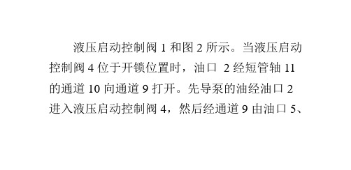
置。在这一位置,限制开关 3 的滑阀 14 向左外 移,直到进入切口 15。此时限制开关 3 位于“关 闭”位置。当液压启动控制阀 4 位于“锁定”位 置时,短管轴 11 向右移动滑阀 14,打开限制开
没有盒子的拘束 没有空间的限制 我肆意扩散 如温柔的野兽离开了囚笼 我期待我的生活 期待有份爱情
没有盒子的拘束 没有空间的限制 我肆意扩散 如温柔的野兽离开了囚笼 我期待我的生活 期待有份爱情
0c10f4ce 太阳城/taiyangcheng/
Байду номын сангаас
关 3,先导泵的油被堵(滞留)在油口 2 和通道 10 之间,通道 12 与短管轴的回油通道 13 接通。因 为先导泵油堵在通道 9,所以来自各先导操纵阀 的回油经通道 9、12 和 13,流出回油口 l 到油泵
吸油腔。此时先导操纵阀杆/踏板的任何操作都 不会推动主控制阀。只有当限制开关 3 打开并且 液压启动控制阀 4 位于“锁定”位置时,才能操 作启动开关。图 1 液压启动控制阀(开锁位置)1-
没有盒子的拘束 没有空间的限制 我肆意扩散 如温柔的野兽离开了囚笼 我期待我的生活 期待有份爱情
回油口;2-油口;3-限制开关;4-液压启动控制 阀;5-油口(先导操纵阀用于回转及斗杆);6-油 口(先导操纵阀用于动臂和铲斗);7-油口(先导 操纵阀用于左行走);8-油口(先导操纵阀用于右
行走);9、10、12-通道;11-短管轴;13-回油通道 图 2 液压启动控制阀 AA 剖面(图 1 的局部)2-油 口;3-限制开关;9、IO-通道;11-短管轴;14-滑 阀;15-切口
液压启动控制阀 1 和图 2 所示。当液压启动 控制阀 4 位于开锁位置时,油口 2 经短管轴 11 的通道 10 向通道 9 打开。先导泵的油经油口 2 进入液压启动控制阀 4,然后经通道 9 由油口 5、
320使用说明书
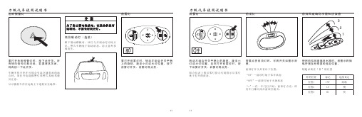
危险报警灯要打开危险报警灯时,按下此开关,所有转向信号灯都闪烁。
若要将其关闭,则再按一下此开关。
车辆不得不停在可能会引起交通事故的地点时,须打开危险报警灯来警告其他驾驶员注意。
尽可能将车停在远离主干道的安全地带。
为了防止蓄电池放电,在发动机没有运转时,不要长时间开灯。
注 意高位制动灯(选装)踩下制动踏板时,该灯与后制动灯同时点亮,警告车辆处于制动状态,防止意外事故发生。
前雾灯要打开前雾灯时,转动左组合开关手柄上的旋钮,旋至小灯或大灯位置,按下前雾灯开关,前雾灯将点亮。
后雾灯转动左组合开关手柄上的旋钮,旋至小灯或大灯位置,且按下后雾灯开关,后雾灯将点亮。
组合仪表上的后雾灯指示灯将指示后雾灯处于打开的状态。
在打开前雾灯时,前顶灯需要点亮前顶灯时,可将开关如图示滑移。
前顶灯开关具有以下位置:“ON”—前顶灯处于常开状态“OFF”—前顶灯处于关闭状态“o”—任一车门打开时,前顶灯点亮。
所有车门都关闭后前顶灯熄灭。
使用前挡风玻璃刮水器时,按图示将操纵杆拨至所需要的设定位置。
钥匙必须在“Ⅱ”的位置前挡风玻璃刮水器和洗涤液仅对挡风玻璃作一次刮扫时,把操纵杆向上抬并释放。
要喷射洗涤液,将操纵杆向上推在喷射了洗涤液之后,应立即释放操纵杆,刮水器还将工作数次。
在寒冷结冰的天气,使用清洁器之前,可先按除霜对挡风玻璃进行加温。
这样可以防止清洁液冻结在挡风玻璃上而影响视线。
挡风玻璃在干燥的状态时,不得使用刮水器,否则会刮伤玻璃。
注 意使用后挡风玻璃刮水器时,按图示将操纵杆拨至所需要的设定位置。
钥匙必须在“Ⅱ”的位置后挡风玻璃刮水器和洗涤液(选装)要喷射洗涤液,将操纵杆向下推在喷射了洗涤液之后,应立即释放操纵杆,刮水器还将工作一次。
后除霜按钮要将后风窗进行除雾或除霜时,按此按钮。
点火开关必须在“Ⅱ”的位置。
后风窗内侧的电热丝将迅速使后风窗表面清晰。
指示灯将发亮,指示除霜在工作中。
再按一次开关,除霜关闭。
后除霜具有延迟功能,除霜器操作约15分钟之后,这个系统将自动关闭。
320C型挖掘机燃油喷射管线拆装说明书
Product: EXCAVATORModel: 320C EXCAVATOR HBCConfiguration: 320C Excavators HBC00001-UP (MACHINE) POWERED BY 3066 EngineDisassembly and Assembly3064 and 3066 Engines for Caterpillar Built MachinesMedia Number -SENR5553-10 Publication Date -01/05/2012 Date Updated -15/05/2012i01565021 Fuel Injection Lines - Remove and InstallSMCS - 1252-010Removal ProcedureStart By:A.Remove the fuel filter base. Refer to Disassembly and Assembly, "Fuel Filter Base -Remove and Install".NOTICEKeep all parts clean from contaminants.Contaminants may cause rapid wear and shortened component life.NOTICECare must be taken to ensure that fluids are contained duringperformance of inspection, maintenance, testing, adjusting and repairof the product. Be prepared to collect the fluid with suitable containersbefore opening any compartment or disassembling any componentcontaining fluids.Refer to Special Publication, NENG2500, "Caterpillar Tools and ShopProducts Guide" for tools and supplies suitable to collect and containfluids on Caterpillar products.Dispose of all fluids according to local regulations and mandates.Illustration 1g00606301The 3066 Engine is shown.1.Remove the bolts (1), the washers, and the clamps (2), which secure the fuel lines to theinlet manifold (3) .Illustration 2g006063102.Disconnect the fuel injection lines (4) from the fuel injection nozzles (5) .Note: Cap all openings or plug all openings immediately in order to prevent contamination of the fuel system.Illustration 3g00606314Fuel injection pump for a 3066 Engine3.Disconnect the end of the fuel injection lines (4) from the fuel injection pump (6) .Note: Cap all openings or plug all openings immediately in order to prevent contamination of the fuel system.4.Remove the fuel injection lines (4) from the engine.Illustration 4g006063175.Loosen the acorn nuts (7), which secure the fuel return line to the fuel injection nozzles.6.Remove one bolt (8) and the washer from the clamp that secures the fuel return line to theintake manifold.Note: The clamp will remain with the fuel return line, when the fuel return line is removed from the engine.7.Disconnect fitting (9). Remove fuel return line (10) from the engine.Note: Cap all openings or plug all openings immediately in order to prevent contamination of the fuel system.Installation ProcedureNOTICEKeep all parts clean from contaminants.Contaminants may cause rapid wear and shortened component life.Illustration 5g006063171.Place the fuel return line (10) in position on the engine. Connect fitting (9) of the fuel returnline to the fuel injection pump.2.Install the washer and bolt (8) through the clamp in order to secure the fuel return line to theinlet manifold.3.Install the fuel return line (10) to the fuel injection nozzles. Secure the fuel return line to thefuel injection nozzle with acorn nuts (7) .Illustration 6g00606399Fuel injection pump for a 3066 Engine4.Place the fuel injection lines (4) on the engine.5.Connect the fuel injection lines (4) to the fuel injection pump (6) .6.Connect the fuel injection lines (4) to the fuel injection nozzles (5) .Note: The fuel lines (4) should be connected at the fuel injection nozzle (5) and at the fuel injection pump (6) before tightening the nuts for the fuel injection line.7.Tighten the nuts for the fuel injection line to a torque of 25 N·m (18 lb ft).Illustration 7g00606301Fuel lines for a 3066 Engine8.Install the clamps (2), the washers, and the bolts (1), which secure the fuel lines to the inletmanifold (3) .End By: Install the fuel filter base. Refer to Disassembly and Assembly, "Fuel Filter Base - Remove and Install".Product: EXCAVATORModel: 320C EXCAVATOR HBCConfiguration: 320C Excavators HBC00001-UP (MACHINE) POWERED BY 3066 EngineDisassembly and Assembly3064 and 3066 Engines for Caterpillar Built MachinesMedia Number -SENR5553-10 Publication Date -01/05/2012 Date Updated -15/05/2012i01151321 Fuel Injection Nozzles - RemoveSMCS - 1254-011Removal ProcedureTable 1Required ToolsTool Part Number Part Description QtyA1U-7600 Slide Hammer Puller 1B9U-6278 Adapter 1Start By:A.Remove the fuel injection lines. Refer to Disassembly and Assembly, "Fuel Injection Lines- Remove and Install".NOTICEKeep all parts clean from contaminants.Contaminants may cause rapid wear and shortened component life.Illustration 1g006523191.Remove bolt (1) and the washer that secures the clamp (2) to the cylinder head assembly.2.Remove the clamp (2) that secures the fuel injection nozzle (3) in position in the cylinderhead assembly.Note: Put caps or plugs on all openings immediately in order to prevent contamination in the fuel system.Note: Mark the clamp for later installation.3.Install Tool (B) (not shown) to the fuel injection nozzle.Note: Tool (B) is installed at the connection (4) for the fuel injection lines.4.Connect Tool (A) (not shown) to Tool (B) in order to carefully remove fuel injection nozzle(3) .Note: Align the centerline of Tool (A) with the extended centerline of fuel injection nozzle(3). This procedure will help prevent distortion of the fuel injection nozzle which can causethe fuel injection nozzle to bend or break.5.Remove the seat washer from the fuel injection nozzle.Product: EXCAVATORModel: 320C EXCAVATOR HBCConfiguration: 320C Excavators HBC00001-UP (MACHINE) POWERED BY 3066 EngineDisassembly and Assembly3064 and 3066 Engines for Caterpillar Built MachinesMedia Number -SENR5553-10 Publication Date -01/05/2012 Date Updated -15/05/2012i01151648 Fuel Injection Nozzles - InstallSMCS - 1254-012Installation ProcedureNOTICEKeep all parts clean from contaminants.Contaminants may cause rapid wear and shortened component life.Illustration 1g006523191.Install a new seat washer (5) .2.Install fuel injection nozzle (3).3.Install clamp (2), the washer, and bolt (1) that secures the fuel injection nozzle to thecylinder head assembly.4.Tighten bolt (1), that secures the fuel injection nozzle, to a torque of 22 N·m (16 lb ft).End By: Install the fuel injection lines. Refer to Disassembly and Assembly, "Fuel Injection Lines - Remove and Install".***************************。
卡特320v显示屏按键说明(一)
卡特320v显示屏按键说明(一)卡特320v显示屏按键说明1. 前言本文将介绍卡特320v显示屏的按键使用说明,帮助用户更好地操作和控制显示屏。
2. 按键布局卡特320v显示屏的按键布局如下:•开关机键:用于打开或关闭显示屏电源。
•亮度调节键:用于调节显示屏的亮度。
•色彩调节键:用于调节显示屏的色彩表现。
•输入源选择键:用于切换不同的输入源。
•菜单键:用于打开或关闭菜单选项。
•方向控制键:用于在菜单选项中进行上下左右移动。
3. 操作步骤以下是使用卡特320v显示屏的按键操作步骤:1.打开电源:按下开关机键,显示屏将开启。
2.调节亮度:使用亮度调节键,根据个人需求增加或减小显示屏的亮度。
3.调节色彩:使用色彩调节键,根据个人需求增加或减小显示屏的色彩表现。
4.切换输入源:按下输入源选择键,可以切换不同的输入源,如HDMI、VGA等。
5.打开菜单选项:按下菜单键,可以打开或关闭显示屏的菜单选项。
6.菜单选项操作:使用方向控制键,在菜单选项中进行上下左右移动,选择相应的菜单选项。
7.确认选择:使用方向控制键,将光标移动到要选择的菜单选项上,按下确认键进行选择。
8.返回上级菜单:在菜单选项中,按下返回键可以返回上一级菜单。
9.关闭显示屏:再次按下开关机键,可以关闭显示屏电源。
4. 小结本文介绍了卡特320v显示屏的按键使用说明,包括按键布局和操作步骤。
通过掌握这些内容,用户可以更好地使用和控制显示屏,享受更好的使用体验。
以上就是卡特320v显示屏按键说明的相关内容。
注意:本文内容仅供参考,具体操作以实际产品为准。
- 1、下载文档前请自行甄别文档内容的完整性,平台不提供额外的编辑、内容补充、找答案等附加服务。
- 2、"仅部分预览"的文档,不可在线预览部分如存在完整性等问题,可反馈申请退款(可完整预览的文档不适用该条件!)。
- 3、如文档侵犯您的权益,请联系客服反馈,我们会尽快为您处理(人工客服工作时间:9:00-18:30)。
油门控制器安装说明书
安装步骤:
1、将油门控制器本体插好电插头固定在底盘上。
2、先将加速拉线(缠绕蓝色胶布的为加速线)和减速拉线的连接球头分别固定在油门操纵杆上并拧紧螺
母。
(注意:加速和减速拉线的螺杆先不要卡在机座上的卡槽内)。
3、回到驾驶室用钥匙打开电源,将“备用开关”转到“手动”位置。
(注意:不要发动发动机,320C 的
“备用开关”在右手臂的位置,320B 的备用开关在右手后面向下的位置)。
4、连续往兔子图标方向拨动几次“手动油门按钮”(每次大约按2秒)保证将油门加到处于最大
的位置(即此时加速器拉线缩到最短)。
按顺时针方向(向右)推动油门操纵杆(如图)使其紧靠到高怠速限位螺栓,此时将加速拉线拉直并使其刚好卡在机座上。
加速拉线安装完成。
5、回到驾驶室将“手动油门按钮”连续往乌龟图标方向拨动几次(每次大约按2秒)保证将油
门减到处于最小的位置(即此时加速器拉线走到最长)。
6、将减速拉线并使卡在机座上。
一般在螺杆中间位置;减速拉线(熄火线)安装完成。
调试步骤:
1、发动机转速调试:将“备用开关”切换到“AUTO ”位置。
启动发动机,查看转速⑴资料选择—⑵输入
密码—⑶选择“机器资料”,按确定。
2、发动机转速校正:校正步骤:⑴资料选择—⑵输入密码“FFF2”—⑶第2行英文选择“CALIBRATION”—⑷第3行英文选择“GOVERNOR-EXE”—⑸第4行英文选择“STANDBY”并按“确定”—⑹出现“SP”以后再次按“确定”—⑺等待校正结束,第1行选择“EXIT”并按“设定键”退出。
3、发动机熄火线位置的调试:调节加速拉线的松紧来将发动机转速调到合理位置,10档达到2000转左右,调节过程中若不能熄火,将细微调熄火线松或者紧到刚好能熄火。
油门控制器安装常见问题:
故障现象原因
解决方法1、发动机转速不正常
加速拉线未安装到位。
·调节加速拉线的松紧直到正确为止。
2、发动机无法熄火
减速电缆太松·将减速拉线慢慢调紧直到刚好能熄火为止。
3、发动机转速没反应⒈油嘴堵塞.
2.点火开关故障
3.电缆没接好·请将发动机档位调到第3挡启动。
·更换点火开关。
·将发动机熄火,并将熄火线调松4圈左右,再
启动校正程序。
(恒威电子QQ :2489464408)。