RFC以太网性能测试规程
RFC2544能测测试

北京信而泰科技有限公司©版权所有1iTesterAPP网络性能测试包含的RFC2544测试一、吞吐量测试标准 RFC2544 26.1节目的这个测试包含了RFC2544的吞吐量(Throughput)测试。
该测试在指定包长下,测量没有包丢失时,被测系统所能转发包的最大速率。
这个基准测试是其它测试的基础。
描述包从测试仪的一个或多个源端口发出,通过被测系统,到达测试仪的目的端口。
如果出现包丢失,将负载减小,重新测试。
如果下一次尝试没有出现包丢失,将负载增加,重新测试。
继续这种二分查找,直到测出没有丢包的最大速率说明:一般在这个过程中同时测试时延。
配置System Under Test过程1 在测试仪上,产生从1源端口到1个目的端口的单向数据流的网络流量(traffic mesh),配置包头、净荷类型、包长等。
2 设定初始负载为被测系统接口使用的最大速率(线路,100%流量)。
3 从所有的源端口到目的端口发送指定长度的包。
完成后,测量所有数据流上发送和接收的包数目。
4 如果出现包丢失,减小负载(调整Load值),重复测试。
5 使用二分法,在后续的反复测试中,继续增加或减小负载,直到成功和失败的负载差异小于测试的分辨度。
这就是零丢失吞吐量。
参数1 包长。
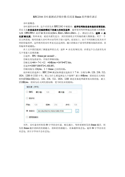
RFC2544中针对以太网帧产生的包长包括:64,128,256,512,1024,1280,1518字节。
2 吞吐量分辨率。
太粗的分辨率可以加快测试,而精确的分辨度将使二分查找算法的收敛时间较长。
北京信而泰科技有限公司©版权所有23 测试时间。
用户可定义测试时长,最大可10000小时以上。
结果对于每一次尝试,记录所有数据流接收和发送的包数目。
对最后一次(成功的)尝试,对给定的包长,记录包速率(格式为:Packet/S,PPS),相对于最大速率的百分比。
二、丢包率测试标准 RFC2544,26.3节目的本测试测量了被测系统负载功能的转发性能。
RFC2544测试原理与设置
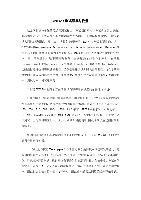
RFC2544测试原理与设置RFC2544测试原理与设置以太网测试与传统的传送网测试相比,测试项目更多,测试内容更加复杂。
但总体来讲包括了协议分析和性能测试两个方面。
在工程现场测试中,一般是以以太网性能为测试主要内容,以服务等级验证(SLA)为测试主要目的。
其中RFC25444(Benchmarking Methodology for Network Interconnect Devices)始终是以太网性能测试的最为主要的内容。
RFC2544是对网络极限性能的一种测试,属于离线测试,通常需要断业务,主要包括了如下四个方面:吞吐量(throughput)、时延(Latency)、丢帧率(FrameLoss)和背对背(BacktoBack),这些指标是评价网络设备的基础,当然也是评价以太网设备的基础,适合于所有以太网互联设备和以太网网络。
在测试中,测试条件的设置非常重要,如测试帧长、测试时间、测试速率等。
下面就RFC2544的四个方面的测试内容和需要设置的条件进行详述:在测试帧长、测试时间、测试速率中,测试帧长对于RFC2544的四项内容来说是需要统一设置的,从最小帧长到MTU顺序递增。
例如在以太网上采用64、128、256、512、768、1024、1280、1518字节。
RFC2544要求对一系列的帧长(64,128,256,512, 768,1024,1280,1518字节)在一定的时间内,按一定的数目进行测试. 因为在网络应用中, 大,中,小帧都可能使用,因此必须了解这些帧的测试结果。
测试时间和测试速率根据测试项的不同会有区别,下面对RFC2544的四个测试项分别进行介绍。
吞吐量(带宽Throughput)吞吐量的概念是测试网络包转发的能力。
通常指网络在不丢包条件下每秒转发包的极限。
一般可以采用二分发查找该极限点,即从线速开始测试,找到网络在不丢包的情况下的最大传输带宽。
测试时间通常不应该少于1分钟,也就是测试仪器会在指定的速率下连续1分钟发送数据包,测试仪表的缺省值一般为1分钟。
RFC2544
RFC2544---- 以太网链路测试基准RFC2544(Benchmarking Methodology for Network Interconnect Devices)提供了一个对网络设备测试的基准,它规定了一系列的测试过程和方法,使得服务提供商和用户间可以在同一个基准下,对测试的实施和结果达成共识。
RFC2544标准要求对一系列的帧长(64,128,256,512, 768,1024,1280,1518字节)在一定的时间内,按一定的数目进行测试。
其主要测试项有吞吐率(Throughput)测试,延时(Latency)测试,帧丢失(Frame Loss Rate)测试和背靠背测试(Back-to-back frames),此外还规定了系统恢复(System recovery)测试和复位测试(Reset)。
数据吞吐率(Throughput)简单来说, 就是从源发送方, 到目的接收方可传输的最大数据量。
对于一个以太网系统,绝对的最大吞吐率应该等同于其接口速率。
而实际上,由于不同的帧长度具有不同的传输效率, 这些绝对的吞吐率是无法达到的. 越小的帧由于前导码和帧间隔的原因,其传输效率就越低.如100M以太网,对于64byte的帧,其最大数据吞吐率(Data Throughput)是76.19MBit/s,每秒可传输148809帧。
对于1518byte帧,则分别为98.69MBit/s和8127帧/s。
然而吞吐率的定义和计算和对服务质量的接受程度有关,因而吞吐率也可以定义为可接受的丢包率范围内的最大传输量。
延时(Latency)是指一个帧从源点到目的点的总传输时间. 这个时间包括网络节点的处理时间,和在传输介质上的传播时间.一般的测试方法是发送一个带有时间戳的帧,通过网络后,在接收方将当时的时间和帧所携带的时间戳比较,从而得出延时值. 考虑到时钟同步问题,一般采用将发出的帧环回到发送方进行比较,因此也称为双程延时.RFC2544要求对延时测试至少需要重复20次,结果取所有测试结果的平均值。
以太网简介与RFC2544测试
以太网简介以太网是一个异步的,基于帧结构的通讯协议。
它最初的出发点是利用共享介质为两个以上的数据终端提供一种通讯方式。
以太网的标准由IEEE 802。
3 (2000)制订。
现有的以太网标准定义了不同的带宽和传输介质类型。
一个以太网物理接口由以下的形式定义:<数据率单位: Mbps>。
<介质类型>。
<最长的电缆段长度单位: 100米>例如,标准中定义的一个10MBPS,电缆段最长距离为500米的基带系统被称为:10BASE5。
如果介质类型为”T”,则代表介质为非屏蔽双绞线。
不同接口的以太网具有相同的帧结构和媒体控制/访问方式(MAC),如果是共享介质,则具有相同的冲突检测方法(CSMA/CD)。
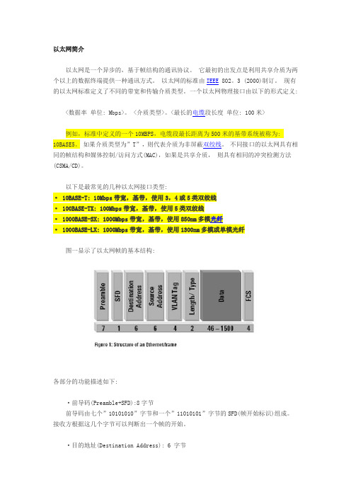
以下是最常见的几种以太网接口类型:· 10BASE-T: 10Mbps带宽,基带,使用3,4或5类双绞线· 100BASE-TX: 100Mbps带宽,基带,使用5类双绞线· 1000BASE-SX: 1000Mbps带宽,基带,使用850nm多模光纤· 1000BASE-LX: 1000Mbps带宽,基带,使用1300nm多模或单模光纤图一显示了以太网帧的基本结构:各部分的功能描述如下:·前导码(Preamble+SFD):8字节前导码由七个”10101010”字节和一个”11010101”字节的SFD(帧开始标识)组成。
接收方根据这几个字节可以判断出一个帧的开始。
·目的地址(Destination Address): 6 字节MAC目的地址,通常用十六进指(HEX)表示。
目的地址被用于在设备之间判断以太网帧的传递方向和路由。
每一个以太网设备通常被分配一个唯一的MAC地址。
而有些特殊的MAC 地址被保留,用于表示一些特殊的功能,例如,全1的地址(FF:FF:FF:FF:FF:FF)用于表示广播地址。
·源地址: 6字节源地址是指发送方的MAC地址。
Smartbit RFC2544测试指导
RFC2544测试指导1.Throughput定义:被测设备在不丢包的情况下,所能转发的最大数据流量。
通常使用每秒钟通过的最大的数据包数或者字节数来衡量(MB/s) 。
作用:反映被测试设备所能够处理(不丢失数据包) 的最大的数据流量。
吞吐量越大,说明处理数据的能力越强。
CTC V2.1标准要求:当EPON系统仅承载以太网/IP业务时,PON接口上行方向的吞吐量应不小于900Mbit/s(64Byte到1518Byte之间的任意包长,1:32分光比下),PON接口上下行方向的吞吐量应不小于950Mbit/s(任意包长)。
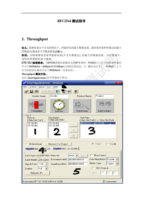
Throughput测试方法:运行SmartApplications,打开界面如下所示:图1.1第一步:点击图1.1中6区中的“SmartBits Cards Status”按钮,打开如下界面,进行仪表板卡占用,不用的仪表板卡释放权限。
占用的处于“Reserved”状态,不占用处于“Available”状态。
图1.2第二步:在图1.1中“1”、“2”区选中仪表上的对应的上下行接口,添加到“3“对应的区域,添加成功后如图1.2所示,选中它,并在“4”区选取源端口或者目的端口进行接口基本属性设置。
如图中“5”区,设置源mac、目的mac、端口速率及接入方式、光口还是电口、协议类型。
注意把“Bi-directional(双向)“选择框选上。
第三步:在图1.1中“6”区,点击“Setup Test Configuration”按钮,打开界面如下图1.3所示:图1.3第四步:点击图1.3中“3”区中的Sizes,选取需要测试的Frame size,最小速率、最大速率,如下图1.4所示:仪表测试的方式是“二分法”(先测试最大速率,如果不过,再测试最小速率,如果最小速率过了,再取最大和最小速率的中间值,一直继续下去直到取到最大的值。
)图1.4然后点击”ok “。
第五步:点击“Throughput”按钮,弹出如下图1.5界面所示:图1.5等待测试结果即可。
RFC2544性能测试方法及测试标准
RFC 2544性能测试方法及测试标准编写人:m0m0p2p2005-5前言RFC 2544下的测试主要包括:吞吐量,时延,丢包率,背靠背。
本文主要说明使用IXI A测试仪及I Xscr iptma te软件进行测试时,测试仪相关配置的调整以及防火墙部分端口和策略的设置。
RFC2544 性能测试方法及标准1.吞吐量测试网络中的数据是由一个个数据包组成,防火墙对每个数据包的处理要耗费资源。
吞吐量是指在没有帧丢失的情况下,设备能够接受的最大速率。
其测试方法是:在测试中以一定速率发送一定数量的帧,并计算待测设备传输的帧,如果发送的帧与接收的帧数量相等,那么就将发送速率提高并重新测试;如果接收帧少于发送帧则降低发送速率重新测试,直至得出最终结果。
吞吐量测试结果以比特/秒或字节/秒表示。
吞吐量是防火墙应用的主要指标,一般采用FD T(Full Duplex Throug hput)来衡量,指数据包的全双工吞吐量,该指标既包括吞吐量指标也涵盖了报文转发率指标。
1.1 测试仪设置方法首先选中左侧T EST目录下面的A T SS-Throug ht-xxx-Config项(如图1)。
如果没有这个选项,可以到下面的l ibra ry目录中找到ATS S-Throug hput右键点击-New Test,建立一个新的测试项目。
(如图2)图1 图2System setup设置方法:Port setup设置方法:注意右侧的s e ttin gs里面的端口自动协商功能应该开启(Auto Negoti ate on)如果使用千兆端口测试百兆设备的时候注意要将端口的SP EED设置为copp er100Traffi c setup设置方法:Framedate选择I P,然后点击ip port names&VLAN IDs进行测试仪端口的I P地址设置,Map选择m a nual,点击conf igure,进行测试ma p的设置,双向测试一般采用交叉式的测试方式:如下图:(注意图右侧的C onfi guremaps)Test setup设置方法:测试采取每个帧的测试时间为1分钟,每个帧进行2次测试。
RFC2544以太网性能测试说明

RFC2544以太网性能测试说明RFC 2544性能测试说明RFC2544测试吞吐量吞吐量是衡量一款设备转发数据包能力的测试。
这个数据是衡量一款防火墙或者路由交换设备的最重要的指标。
测试吞吐量首先根据标称性能确定被测试设备的可能吞吐量大小,这样来决定我们测试一款设备所需要的测试仪端口数量。
如果一块设备标称性能达到8Gbps,那么通常我们需要8个1000Mbps的测试仪端口来测试。
吞吐量的测试通常会选用测试仪所对应的RFC测试套件进行测试。
测试的数据包长包括64Bytes,128Bytes,256Bytes,512Bytes,1024Bytes,1240Bytes,1518Bytes。
或者使用特定包长或者混合包长(IMIX)进行测试。
IMIX流量通常是指用几种数据包混合流量来测试防火墙的吞吐量。
我们测试用的比例为64Bytes*58%+570Bytes*34%+1518Bytes*8%,也就是7:4:1。
如果需要测试VPN的吞吐量,不能使用1518Bytes,因为会分片,一般改用1400字节测试。
吞吐量一般采用UDP数据包进行测试。
测试通常采用双向各一条流或者多条流的方式测试。
测试流量通常是A<->B,C<->D双向对打的流量。
使用单向流量测试的情况比较少见。
测试仪通常都会采用二分迭代法进行测试。
比如测试仪会首先使用100%的流量发包(1st trial),如果发现丢包,则会采用50%((100%+0)/2)的流量进行测试(2nd trial),如果发现没有丢包,会采用75%((50%+100%)/2)的流量进行测试(3rd trial)。
通过这种二分迭代的测试最终测试出设备的最大吞吐量数据。
我们内部测试的时候每一个trial的时间设置为30秒,每个包长通常会进行8个trial的测试(取决于测试仪设置的精确度)。
由于测试仪会严格判断是否有丢包,即使有一个包没有收到,都会用二分法往下降。
网络测试以太网测试

2.1 以太网技术家族
名称 带宽
拓扑
组网方式
标准 适用范围
标准以太网 10M 总线/星型 共享/交换 IEEE802.3 局域网
但连接交叉矩阵的总线成为新的性能瓶颈。
2.7 交换机的转发方式
交换机将数据从一个端口转发至到另一个 端口的处理方式称为交换模式。
类型:
直接交换(cut-through)和存储转发(store-and-forward)
直接交换模式又分成快速转发(fast-forward)与无碎片 (Fragment-free)交换。
交换机的体系结构--共享总线型
交换端口通过ASIC芯片同高速总线相连,数据由 端口传输至ASIC芯片,ASIC芯片根据目的地址 通过高速总线将数据传至目的端口。 为了解决多个端口并发访问共享数据总线所产生 的竞争或冲突,还引入了仲裁机制。
交换机的体系结构--共享总线型
两种数据交换实现方式 集中式交换方式 分布式交换方式
快速转发 具有最小的延时 不提供帧的错误检测
快速转发交换方式
快速转发有两个问题:
(1)它会转发小于64字节的破碎帧和错误帧; (2)该方法要求交换机的所有端口要以同样的速率工作。
也就是说,如果交换机的大部分端口是10Mbps的, 那么这台交换机上就不能有快速以太网的端口。
原因在于快速转发法在转发帧的过程中不能有任何间 隙,而任何时候从低速率转换到高速率时都会有一个间隙, 除非使用某种类型的缓冲。
二层测试的必要性
RFC2544以太网性能测试规程
1RFC2544 概述IP网络设备是IP网络的核心,其性能的好坏直接影响IP网网络规模、网络稳定性以及网络可扩展性。
由于IETF没有对特定设备性能测试作专门规定,一般来说只能按照RFC2544(Benchmarking Methodology for Network Interconnect Devices)作测试。
以太网交换机测试标准则参照RFC2889(Benchmarking Methodology for LAN Sw itching Devices)。
但是由于网络互联设备除了通用性能测试以外通常还有一些特定的性能指标。
例如路由器区别于一般简单的网络互连设备,在性能测试时还应该加上路由器特有的性能测试。
例如路有表容量、路由协议收敛时间等指标。
网络互联设备例如路由器性能测试应当包括下列指标:吞吐量(Throughput):测试路由器包转发的能力。
通常指路由器在不丢包条件下每秒转发包的极限。
一般可以采用二分发查找该极限点。
时延(Latency):测试路由器在吞吐量围从收到包到转发出该包的时间间隔。
时延测试应当重复20次然后去其平均值。
丢包率(Packet loss rate):测试路由器在不同负荷下丢弃包占收到包的比例。
不同负荷通常指从吞吐量测试到线速(线路上传输包的最高速率),步长一般使用线速的10%。
背靠背帧数(Back-to-back frame):测试路由器在接收到以最小包间隔传输时不丢包条件下所能处理的最大包数。
该测试实际考验路由器缓存能力。
如果路由器具备线速能力(吞吐量=接口媒体线速),则该测试没有意义。
系统恢复时间(System recovery):测试路由器在过载后恢复正常工作的时间。
测试方法可以采用向路由器端口发送吞吐量110%和线速间的较小值持续60秒后将速率下降到50%的时刻到最后一个丢包的时间间隔。
如果路由器具备线速能力,则该测试没有意义。
系统复位(Reset):测试路由器从软件复位或关电重启到正常工作的时间间隔。
RFC2544性能测试
RFC2544性能测试什么是RFC 2544?⽹络设备性能测试的⼀组指标,包括吞吐率、时延、丢包率、背靠背。
* * *吞吐率(Throughput). 定义:被测设备在不丢包的情况下,所能转发的最⼤数据流量。
通常使⽤每秒钟通过的最⼤的数据包数或者字节数来衡量。
· 作⽤:反映被测试设备所能够处理(不丢失数据包) 的最⼤的数据流量。
ps:使⽤仪表(IXIA 等)测试时可以使⽤内置的测试模板,再没有仪表的情况下可以使⽤折半打流观察丢包的⽅法。
##### 仪表测试模板有⼏个关键参数需要注意:1. 打流时长,当中间设备带宽较⼩时建议测试样本增加时长。
2. 精度:精度不能太⾼也不能太低,太⾼折半的次数过多,增加测试时间;过低测出的值与理论值偏差过⼤。
3. 时延抖动:吞吐率和时延是同时测试的,注意关注抖动。
时延(Latency)· 定义:发送⼀定数量的数据包,记录中间数据包发出的时间T1,以及经由测试设备转发后到达接收端⼝的时间T2,然后按照下⾯的公式计算:对于存储/位转发设备: Latency = T2 - T1T2:输出帧的第⼀位到达输出端⼝的时间;T1:输⼊帧的最后⼀位到达输⼊端⼝的时间。
· 作⽤:反映被测设备处理数据包的速度。
##### 分析注意点:1、时延分为平均时延和时延抖动。
平均时延:就是⼀组数据传输后每个帧传输所需时间的平均值。
时延抖动:⽹络上连续传输的数据包即便使⽤相同的路径,也会有不同的延时,每个数据包之间的这种延时不⼀致称为抖动。
在即时通信场景抖动是⾮常重要的。
抖动引起的丢包和⽹络拥塞会影响语⾳视频质量。
2、时延测试建议打⼩包长。
3、建议每秒发包数少,必须⼩于设备处理能⼒。
如果包长和发包数较⼤导致丢包或者拥塞就⽆法测试出真实的时延。
注意:对于存储转发设备来说,当输⼊帧的最后⼀位到达输⼊端⼝时,开始计时。
当输出帧的第⼀位到达输出端⼝上可见时,计时结束。
延迟越⼤说明交换机处理帧的速度越慢。
RFC 2889以太网转发性能测试实验
南京邮电大学自动化学院实验报告实验名称:RFC 2889以太网转发性能测试实验课程名称:网络测试技术所在专业:学生姓名:班级学号:任课教师:戴尔晗2014 /2015 学年第二学期实验1 RFC 2889以太网转发性能测试实验一实验目的●理解交换机转发性能测试的主要技术指标。
●掌握RFC 2889 以太网最大转发速率测试的设计思想与基本方法。
●掌握运用测试仪表向导(Wizard)功能进行以太网单向和全网状最大转发速率测试的基本技能。
二实验环境与拓扑本实验的物理环境如图1.1所示,由一台被测试交换机(DUT)、一台测试仪表和一台计算机组成。
其中,计算机作为测试仪表的用户终端。
测试仪表上的以太网端口通过直连线与DUT上的测试端口相连。
图1.1 以太网交换机转发性能测试的物理连接进行以太网单向最大转发速率测试时需要选用DUT上的至少2个端口组成一个测试回路,一路发送,一路接收。
这2个端口组成的全网状测试拓扑如图1.2所示。
图1.2 2个端口的单向连接进行以太网全网状最大转发速率测试时至少要选用DUT上的4个端口组成一个全网状的测试块,同时这4个端口要求未被进行VLAN划分或是处于同一个VLAN中。
这4个端口组成的全网状测试拓扑如图1.3所示。
图1.3 4个端口的全网状连接三实验内容及其规划通过测试仪表所提供的测试向导(Wizard)进行RFC 2889以太网最大转发速率测试。
在运行测试之前,需要首先就表1.1中所列出的有关测试参数进行必要的规划。
表1.1中给出了相应的建议值,读者可根据实际情况确定相应的设置。
表1.1 以太网最大转发速率测试的有关参数参数名称参数描述建议设置测试时间(Test Duration)每次测试运行持续的时间1~300s之间调整,推荐10s/5s 实验次数(Number of Trials)测试运行的次数1次每个端口的地址数(Addresses Per Port)测试仪表端口发出的测试流中所包含的不同帧目的地址数按照2n方式去进行设置,参考值为1地址格式(Address format)以太网地址的格式十六进制或二进制帧大小(Frame Sizes)测试帧的长度选择长度64、128、256、512、1024、1280和1518字节中的至少2种帧格式(Frame Format)测试帧的格式EthernetⅡ帧突发传输量(Burst Size)一次突发传输中所包含的帧数可在1~930帧间调整,1表示恒定传输负载百分率(Load Percentage)以媒质最大理论负载之百分比表示的期望负载80%-100%四实验步骤通常,一个完整的测试过程有以下几个阶段组成:测试环境的搭建、测试设置、测试运行、测试结果保存与分析。
rfc中常用的测试协议

rfc中常用的测试协议引言在计算机网络领域中,为了确保网络协议的正确性和稳定性,测试协议起到了至关重要的作用。
RFC(Request for Comments)是一系列文件,用于描述互联网相关协议、过程和技术。
在RFC中,也包含了一些常用的测试协议,用于验证和评估网络协议的功能和性能。
本文将介绍RFC中常用的测试协议,并深入探讨其原理和应用。
二级标题1:PING协议三级标题1.1:概述PING协议是一种常用的网络测试协议,用于测试主机之间的连通性。
它基于ICMP (Internet Control Message Protocol)协议,通过发送ICMP Echo Request报文并等待目标主机的ICMP Echo Reply报文来判断目标主机是否可达。
三级标题1.2:工作原理PING协议的工作原理如下: 1. 发送方主机生成一个ICMP Echo Request报文,并将目标主机的IP地址作为目的地。
2. 发送方主机将报文发送到网络中。
3.中间路由器收到报文后,将报文转发到下一跳路由器。
4. 目标主机收到ICMP Echo Request报文后,生成一个ICMP Echo Reply报文,并将其发送回发送方主机。
5. 发送方主机收到ICMP Echo Reply报文后,通过比较报文中的标识符和序列号等字段,判断目标主机是否可达。
三级标题1.3:应用场景PING协议在网络中的应用非常广泛,常用于以下场景: - 测试主机之间的连通性,判断网络是否正常工作。
- 测试网络延迟,通过计算ICMP Echo Request报文的往返时间来评估网络质量。
- 排查网络故障,通过检查ICMP Echo Reply报文中的错误码来定位故障原因。
二级标题2:Traceroute协议三级标题2.1:概述Traceroute协议用于跟踪数据包从源主机到目标主机经过的路径。
它通过发送一系列的UDP报文,并在每个报文中设置不同的TTL(Time to Live)值来实现。
RFC以太网性能测试规程
1RFC2544 概述IP网络设备是IP网络的核心,其性能的好坏直接影响IP网网络规模、网络稳定性以及网络可扩展性。
由于IETF没有对特定设备性能测试作专门规定,一般来说只能按照RFC2544(Benchmarking Methodology for Network Interconnect Devices)作测试。
以太网交换机测试标准则参照RFC2889(Benchmarking Methodology for LAN Sw itching Devices)。
但是由于网络互联设备除了通用性能测试以外通常还有一些特定的性能指标。
例如路由器区别于一般简单的网络互连设备,在性能测试时还应该加上路由器特有的性能测试。
例如路有表容量、路由协议收敛时间等指标。
网络互联设备例如路由器性能测试应当包括下列指标:吞吐量(Throughput):测试路由器包转发的能力。
通常指路由器在不丢包条件下每秒转发包的极限。
一般可以采用二分发查找该极限点。
时延(Latency):测试路由器在吞吐量范围内从收到包到转发出该包的时间间隔。
时延测试应当重复20次然后去其平均值。
丢包率(Packet loss rate):测试路由器在不同负荷下丢弃包占收到包的比例。
不同负荷通常指从吞吐量测试到线速(线路上传输包的最高速率),步长一般使用线速的10%。
背靠背帧数(Back-to-back frame):测试路由器在接收到以最小包间隔传输时不丢包条件下所能处理的最大包数。
该测试实际考验路由器缓存能力。
如果路由器具备线速能力(吞吐量=接口媒体线速),则该测试没有意义。
系统恢复时间(System recovery):测试路由器在过载后恢复正常工作的时间。
测试方法可以采用向路由器端口发送吞吐量110%和线速间的较小值持续60秒后将速率下降到50%的时刻到最后一个丢包的时间间隔。
如果路由器具备线速能力,则该测试没有意义。
系统复位(Reset):测试路由器从软件复位或关电重启到正常工作的时间间隔。
RFC2544 测试规范
Network Working Group S. BradnerRequest for Comments: 2544 Harvard UniversityObsoletes: 1944 J. McQuaidCategory: Informational NetScout SystemsMarch 1999Benchmarking Methodology for Network Interconnect Devices Status of this MemoThis memo provides information for the Internet community. It does not specify an Internet standard of any kind. Distribution of this memo is unlimited.Copyright NoticeCopyright (C) The Internet Society (1999). All Rights Reserved. IESG NoteThis document is a republication of RFC 1944 correcting the values for the IP addresses which were assigned to be used as the default addresses for networking test equipment. (See section C.2.2 ). This RFC replaces and obsoletes RFC 1944.AbstractThis document discusses and defines a number of tests that may be used to describe the performance characteristics of a networkinterconnecting device. In addition to defining the tests this document also describes specific formats for reporting the results of the tests. Appendix A lists the tests and conditions that we believe should be included for specific cases and gives additionalinformation about testing practices. Appendix B is a referencelisting of maximum frame rates to be used with specific frame sizes on various media and Appendix C gives some examples of frame formats to be used in testing.1. IntroductionVendors often engage in "specsmanship" in an attempt to give their products a better position in the marketplace. This often involves "smoke & mirrors" to confuse the potential users of the products.Bradner & McQuaid Informational [Page 1]RFC 2544 Benchmarking Methodology March 1999This document defines a specific set of tests that vendors can use to measure and report the performance characteristics of networkdevices. The results of these tests will provide the user comparable data from different vendors with which to evaluate these devices.A previous document, "Benchmarking Terminology for NetworkInterconnect Devices" (RFC 1242), defined many of the terms that are used in this document. The terminology document should be consulted before attempting to make use of this document.2. Real worldIn producing this document the authors attempted to keep in mind the requirement that apparatus to perform the described tests mustactually be built. We do not know of "off the shelf" equipmentavailable to implement all of the tests but it is our opinion that such equipment can be constructed.3. Tests to be runThere are a number of tests described in this document. Not all of the tests apply to all types of devices under test (DUTs). Vendors should perform all of the tests that can be supported by a specific type of product. The authors understand that it will take aconsiderable period of time to perform all of the recommended tests nder all of the recommended conditions. We believe that the results are worth the effort. Appendix A lists some of the tests andconditions that we believe should be included for specific cases.4. Evaluating the resultsPerforming all of the recommended tests will result in a great deal of data. Much of this data will not apply to the evaluation of the devices under each circumstance. For example, the rate at which a router forwards IPX frames will be of little use in selecting arouter for an environment that does not (and will not) support that protocol. Evaluating even that data which is relevant to aparticular network installation will require experience which may not be readily available. Furthermore, selection of the tests to be run and evaluation of the test data must be done with an understanding of generally accepted testing practices regarding repeatability,variance and statistical significance of small numbers of trials.Bradner & McQuaid Informational [Page 2]RFC 2544 Benchmarking Methodology March 19995. RequirementsIn this document, the words that are used to define the significance of each particular requirement are capitalized. These words are:* "MUST" This word, or the words "REQUIRED" and "SHALL" mean thatthe item is an absolute requirement of the specification.* "SHOULD" This word or the adjective "RECOMMENDED" means that there may exist valid reasons in particular circumstances to ignore this item, but the full implications should beunderstood and the case carefully weighed before choosing a different course.* "MAY" This word or the adjective "OPTIONAL" means that this item is truly optional. One vendor may choose to include the item because a particular marketplace requires it or because it enhances the product, for example; another vendor may omit the same item.An implementation is not compliant if it fails to satisfy one or more of the MUST requirements for the protocols it implements. Animplementation that satisfies all the MUST and all the SHOULDrequirements for its protocols is said to be "unconditionallycompliant"; one that satisfies all the MUST requirements but not all the SHOULD requirements for its protocols is said to be"conditionally compliant".6. Test set upThe ideal way to implement this series of tests is to use a tester with both transmitting and receiving ports. Connections are made from the sending ports of the tester to the receiving ports of the DUT and from the sending ports of the DUT back to the tester. (see Figure 1) Since the tester both sends the test traffic and receives it back, after the traffic has been forwarded but the DUT, the tester can easily determine if all of the transmitted packets were received and verify that the correct packets were received. The samefunctionality can be obtained with separate transmitting andreceiving devices (see Figure 2) but unless they are remotelycontrolled by some computer in a way that simulates the singletester, the labor required to accurately perform some of the tests (particularly the throughput test) can be prohibitive.Bradner & McQuaid Informational [Page 3]RFC 2544 Benchmarking Methodology March 1999+------------+| |+------------| tester |<-------------+| | | || +------------+ || || +------------+ || | | |+----------->| DUT |--------------+| |+------------+Figure 1+--------+ +------------+ +----------+| | | | | || sender |-------->| DUT |--------->| receiver || | | | | |+--------+ +------------+ +----------+Figure 26.1 Test set up for multiple media typesTwo different setups could be used to test a DUT which is used in real-world networks to connect networks of differing media type, local Ethernet to a backbone FDDI ring for example. The tester could support both media types in which case the set up shown in Figure 1 would be used.Two identical DUTs are used in the other test set up. (see Figure 3) In many cases this set up may more accurately simulate the realworld. For example, connecting two LANs together with a WAN link or high speed backbone. This set up would not be as good at simulating a system where clients on a Ethernet LAN were interacting with a server on an FDDI backbone.+-----------+| |+---------------------| tester |<---------------------+ | | | | | +-----------+ | | | | +----------+ +----------+ | | | | | | | +------->| DUT 1 |-------------->| DUT 2 |---------+ | | | |+----------+ +----------+Figure 3Bradner & McQuaid Informational [Page 4]RFC 2544 Benchmarking Methodology March 19997. DUT set upBefore starting to perform the tests, the DUT to be tested MUST be configured following the instructions provided to the user.Specifically, it is expected that all of the supported protocols will be configured and enabled during this set up (See Appendix A). It is expected that all of the tests will be run without changing theconfiguration or setup of the DUT in any way other than that required to do the specific test. For example, it is not acceptable to change the size of frame handling buffers between tests of frame handling rates or to disable all but one transport protocol when testing the throughput of that protocol. It is necessary to modify theconfiguration when starting a test to determine the effect of filters on throughput, but the only change MUST be to enable the specific filter. The DUT set up SHOULD include the normally recommendedrouting update intervals and keep alive frequency. The specific version of the software and the exact DUT configuration, including what functions are disabled, used during the tests MUST be included as part of the report of the results.8. Frame formatsThe formats of the test frames to use for TCP/IP over Ethernet are shown in Appendix C: Test Frame Formats. These exact frame formats SHOULD be used in the tests described in this document for thisprotocol/media combination and that these frames will be used as a template for testing other protocol/media combinations. The specific formats that are used to define the test frames for a particular test series MUST be included in the report of the results.9. Frame sizesAll of the described tests SHOULD be performed at a number of frame sizes. Specifically, the sizes SHOULD include the maximum and minimum legitimate sizes for the protocol under test on the media under test and enough sizes in between to be able to get a full characterization of the DUT performance. Except where noted, at least five frame sizes SHOULD be tested for each test condition.Theoretically the minimum size UDP Echo request frame would consist of an IP header (minimum length 20 octets), a UDP header (8 octets) and whatever MAC level header is required by the media in use. The theoretical maximum frame size is determined by the size of thelength field in the IP header. In almost all cases the actualmaximum and minimum sizes are determined by the limitations of the media.Bradner & McQuaid Informational [Page 5]RFC 2544 Benchmarking Methodology March 1999In theory it would be ideal to distribute the frame sizes in a way that would evenly distribute the theoretical frame rates. These recommendations incorporate this theory but specify frame sizes which are easy to understand and remember. In addition, many of the same frame sizes are specified on each of the media types to allow for easy performance comparisons.Note: The inclusion of an unrealistically small frame size on some ofthe media types (i.e. with little or no space for data) is to help characterize the per-frame processing overhead of the DUT.9.1 Frame sizes to be used on Ethernet64, 128, 256, 512, 1024, 1280, 1518These sizes include the maximum and minimum frame sizes permitted by the Ethernet standard and a selection of sizes between these extremes with a finer granularity for the smaller frame sizes and higher frame rates.9.2 Frame sizes to be used on 4Mb and 16Mb token ring54, 64, 128, 256, 1024, 1518, 2048, 4472The frame size recommendations for token ring assume that there is no RIF field in the frames of routed protocols. A RIF field would be present in any direct source route bridge performance test. The minimum size frame for UDP on token ring is 54 octets. The maximum size of 4472 octets is recommended for 16Mb token ring instead of the theoretical size of 17.9Kb because of the size limitations imposed by many token ring interfaces. The reminder of the sizes are selected to permit direct comparisons with other types of media. An IP (i.e. not UDP) frame may be used in addition if a higher data rate isdesired, in which case the minimum frame size is 46 octets.9.3 Frame sizes to be used on FDDI54, 64, 128, 256, 1024, 1518, 2048, 4472The minimum size frame for UDP on FDDI is 53 octets, the minimum size of 54 is recommended to allow direct comparison to token ringperformance. The maximum size of 4472 is recommended instead of the theoretical maximum size of 4500 octets to permit the same type of comparison. An IP (i.e. not UDP) frame may be used in addition if a higher data rate is desired, in which case the minimum frame size is 45 octets.Bradner & McQuaid Informational [Page 6]RFC 2544 Benchmarking Methodology March 19999.4 Frame sizes in the presence of disparate MTUsWhen the interconnect DUT supports connecting links with disparate MTUs, the frame sizes for the link with the *larger* MTU SHOULD be used, up to the limit of the protocol being tested. If theinterconnect DUT does not support the fragmenting of frames in the presence of MTU mismatch, the forwarding rate for that frame size shall be reported as zero.For example, the test of IP forwarding with a bridge or router that joins FDDI and Ethernet should use the frame sizes of FDDI when going from the FDDI to the Ethernet link. If the bridge does not support IP fragmentation, the forwarding rate for those frames too large for Ethernet should be reported as zero.10. Verifying received framesThe test equipment SHOULD discard any frames received during a test run that are not actual forwarded test frames. For example, keep- alive and routing update frames SHOULD NOT be included in the count of received frames. In any case, the test equipment SHOULD verify the length of the received frames and check that they match theexpected length.Preferably, the test equipment SHOULD include sequence numbers in the transmitted frames and check for these numbers on the receivedframes. If this is done, the reported results SHOULD include in addition to the number of frames dropped, the number of frames that were received out of order, the number of duplicate frames received and the number of gaps in the received frame numbering sequence. This functionality is required for some of the described tests.11. ModifiersIt might be useful to know the DUT performance under a number of conditions; some of these conditions are noted below. The reported results SHOULD include as many of these conditions as the testequipment is able to generate. The suite of tests SHOULD be first run without any modifying conditions and then repeated under each of the conditions separately. To preserve the ability to compare the results of these tests any frames that are required to generate the modifying conditions (management queries for example) will beincluded in the same data stream as the normal test frames in place of one of the test frames and not be supplied to the DUT on aseparate network port.Bradner & McQuaid Informational [Page 7]RFC 2544 Benchmarking Methodology March 199911.1 Broadcast framesIn most router designs special processing is required when frames addressed to the hardware broadcast address are received. In bridges (or in bridge mode on routers) these broadcast frames must be flooded to a number of ports. The stream of test frames SHOULD be augmented with 1% frames addressed to the hardware broadcast address. The frames sent to the broadcast address should be of a type that the router will not need to process. The aim of this test is todetermine if there is any effect on the forwarding rate of the other data in the stream. The specific frames that should be used are included in the test frame format document. The broadcast frames SHOULD be evenly distributed throughout the data stream, for example, every 100th frame.The same test SHOULD be performed on bridge-like DUTs but in this case the broadcast packets will be processed and flooded to alloutputs.It is understood that a level of broadcast frames of 1% is muchhigher than many networks experience but, as in drug toxicityevaluations, the higher level is required to be able to gage the effect which would otherwise often fall within the normal variabilityof the system performance. Due to design factors some test equipment will not be able to generate a level of alternate frames this low. In these cases the percentage SHOULD be as small as the equipment can provide and that the actual level be described in the report of the test results.11.2 Management framesMost data networks now make use of management protocols such as SNMP. In many environments there can be a number of management stations sending queries to the same DUT at the same time.The stream of test frames SHOULD be augmented with one management query as the first frame sent each second during the duration of the trial. The result of the query must fit into one response frame. The response frame SHOULD be verified by the test equipment. One example of the specific query frame that should be used is shown in Appendix C.11.3 Routing update framesThe processing of dynamic routing protocol updates could have asignificant impact on the ability of a router to forward data frames. The stream of test frames SHOULD be augmented with one routing update frame transmitted as the first frame transmitted during the trial.Bradner & McQuaid Informational [Page 8]RFC 2544 Benchmarking Methodology March 1999Routing update frames SHOULD be sent at the rate specified inAppendix C for the specific routing protocol being used in the test. Two routing update frames are defined in Appendix C for the TCP/IP over Ethernet example. The routing frames are designed to change the routing to a number of networks that are not involved in theforwarding of the test data. The first frame sets the routing table state to "A", the second one changes the state to "B". The frames MUST be alternated during the trial.The test SHOULD verify that the routing update was processed by the DUT.11.4 FiltersFilters are added to routers and bridges to selectively inhibit the forwarding of frames that would normally be forwarded. This isusually done to implement security controls on the data that isaccepted between one area and another. Different products havedifferent capabilities to implement filters.The DUT SHOULD be first configured to add one filter condition and the tests performed. This filter SHOULD permit the forwarding of the test data stream. In routers this filter SHOULD be of the form:forward input_protocol_address to output_protocol_addressIn bridges the filter SHOULD be of the form:forward destination_hardware_addressThe DUT SHOULD be then reconfigured to implement a total of 25filters. The first 24 of these filters SHOULD be of the form:block input_protocol_address to output_protocol_addressThe 24 input and output protocol addresses SHOULD not be any that are represented in the test data stream. The last filter SHOULD permit the forwarding of the test data stream. By "first" and "last" we mean to ensure that in the second case, 25 conditions must be checked before the data frames will match the conditions that permit the forwarding of the frame. Of course, if the DUT reorders the filters or does not use a linear scan of the filter rules the effect of the sequence in which the filters are input is properly lost.The exact filters configuration command lines used SHOULD be included with the report of the results.Bradner & McQuaid Informational [Page 9]RFC 2544 Benchmarking Methodology March 199911.4.1 Filter AddressesTwo sets of filter addresses are required, one for the single filter case and one for the 25 filter case.The single filter case should permit traffic from IP address198.18.1.2 to IP address 198.19.65.2 and deny all other traffic. The 25 filter case should follow the following sequence.deny aa.ba.1.1 to aa.ba.100.1deny aa.ba.2.2 to aa.ba.101.2deny aa.ba.3.3 to aa.ba.103.3...deny aa.ba.12.12 to aa.ba.112.12allow aa.bc.1.2 to aa.bc.65.1deny aa.ba.13.13 to aa.ba.113.13deny aa.ba.14.14 to aa.ba.114.14...deny aa.ba.24.24 to aa.ba.124.24deny all elseAll previous filter conditions should be cleared from the router before this sequence is entered. The sequence is selected to test to see if the router sorts the filter conditions or accepts them in the order that they were entered. Both of these procedures will result in a greater impact on performance than will some form of hashcoding.12. Protocol addressesIt is easier to implement these tests using a single logical stream of data, with one source protocol address and one destinationprotocol address, and for some conditions like the filters described above, a practical requirement. Networks in the real world are not limited to single streams of data. The test suite SHOULD be first run with a single protocol (or hardware for bridge tests) source and destination address pair. The tests SHOULD then be repeated withusing a random destination address. While testing routers theaddresses SHOULD be random and uniformly distributed over a range of 256 networks and random and uniformly distributed over the full MAC range for bridges. The specific address ranges to use for IP are shown in Appendix C.Bradner & McQuaid Informational [Page 10]RFC 2544 Benchmarking Methodology March 199913. Route Set UpIt is not reasonable that all of the routing information necessary to forward the test stream, especially in the multiple address case, will be manually set up. At the start of each trial a routing update MUST be sent to the DUT. This routing update MUST include all of the network addresses that will be required for the trial. All of the addresses SHOULD resolve to the same "next-hop". Normally this will be the address of the receiving side of the test equipment. This routing update will have to be repeated at the interval required by the routing protocol being used. An example of the format andrepetition interval of the update frames is given in Appendix C. 14. Bidirectional trafficNormal network activity is not all in a single direction. To test the bidirectional performance of a DUT, the test series SHOULD be run with the same data rate being offered from each direction. The sum of the data rates should not exceed the theoretical limit for the media.15. Single stream pathThe full suite of tests SHOULD be run along with whatever modifier conditions that are relevant using a single input and output network port on the DUT. If the internal design of the DUT has multipledistinct pathways, for example, multiple interface cards each with multiple network ports, then all possible types of pathways SHOULD be tested separately.16. Multi-portMany current router and bridge products provide many network ports in the same module. In performing these tests first half of the ports are designated as "input ports" and half are designated as "output ports". These ports SHOULD be evenly distributed across the DUT architecture. For example if a DUT has two interface cards each of which has four ports, two ports on each interface card are designated as input and two are designated as output. The specified tests are run using the same data rate being offered to each of the inputports. The addresses in the input data streams SHOULD be set so that a frame will be directed to each of the output ports in sequence so that all "output" ports will get an even distribution of packets from this input. The same configuration MAY be used to perform abidirectional multi-stream test. In this case all of the ports are considered both input and output ports and each data stream MUST consist of frames addressed to all of the other ports.Bradner & McQuaid Informational [Page 11]RFC 2544 Benchmarking Methodology March 1999Consider the following 6 port DUT:-----------------------| in A out X|-----------------| in B out Y|-----------------| in C out Z|----------------------The addressing of the data streams for each of the inputs SHOULD be: stream sent to input A:packet to out X, packet to out Y, packet to out Zstream sent to input B:packet to out X, packet to out Y, packet to out Zstream sent to input Cpacket to out X, packet to out Y, packet to out ZNote that these streams each follow the same sequence so that 3packets will arrive at output X at the same time, then 3 packets at Y, then 3 packets at Z. This procedure ensures that, as in the real world, the DUT will have to deal with multiple packets addressed to the same output at the same time.17. Multiple protocolsThis document does not address the issue of testing the effects of a mixed protocol environment other than to suggest that if such tests are wanted then frames SHOULD be distributed between all of the test protocols. The distribution MAY approximate the conditions on the network in which the DUT would be used.18. Multiple frame sizesThis document does not address the issue of testing the effects of a mixed frame size environment other than to suggest that if such tests are wanted then frames SHOULD be distributed between all of thelisted sizes for the protocol under test. The distribution MAYapproximate the conditions on the network in which the DUT would be used. The authors do not have any idea how the results of such a test would be interpreted other than to directly compare multiple DUTs in some very specific simulated network.19. Testing performance beyond a single DUT.In the performance testing of a single DUT, the paradigm can bedescribed as applying some input to a DUT and monitoring the output. The results of which can be used to form a basis of characterization of that device under those test conditions.Bradner & McQuaid Informational [Page 12]RFC 2544 Benchmarking Methodology March 1999This model is useful when the test input and output are homogenous (e.g., 64-byte IP, 802.3 frames into the DUT; 64 byte IP, 802.3frames out), or the method of test can distinguish between dissimilar input/output. (E.g., 1518 byte IP, 802.3 frames in; 576 byte,fragmented IP, X.25 frames out.)By extending the single DUT test model, reasonable benchmarksregarding multiple DUTs or heterogeneous environments may becollected. In this extension, the single DUT is replaced by a system of interconnected network DUTs. This test methodology would support the benchmarking of a variety of device/media/service/protocolcombinations. For example, a configuration for a LAN-to-WAN-to-LAN test might be:(1) 802.3-> DUT 1 -> X.25 @ 64kbps -> DUT 2 -> 802.3Or a mixed LAN configuration might be:(2) 802.3 -> DUT 1 -> FDDI -> DUT 2 -> FDDI -> DUT 3 -> 802.3In both examples 1 and 2, end-to-end benchmarks of each system could be empirically ascertained. Other behavior may be characterizedthrough the use of intermediate devices. In example 2, theconfiguration may be used to give an indication of the FDDI to FDDI capability exhibited by DUT 2.Because multiple DUTs are treated as a single system, there arelimitations to this methodology. For instance, this methodology may yield an aggregate benchmark for a tested system. That benchmark alone, however, may not necessarily reflect asymmetries in behavior between the DUTs, latencies introduce by other apparatus (e.g.,CSUs/DSUs, switches), etc.Further, care must be used when comparing benchmarks of different systems by ensuring that the DUTs' features/configuration of the tested systems have the appropriate common denominators to allow comparison.20. Maximum frame rateThe maximum frame rates that should be used when testing LANconnections SHOULD be the listed theoretical maximum rate for the frame size on the media.Bradner & McQuaid Informational [Page 13]RFC 2544 Benchmarking Methodology March 1999The maximum frame rate that should be used when testing WANconnections SHOULD be greater than the listed theoretical maximum rate for the frame size on that speed connection. The higher rate for WAN tests is to compensate for the fact that some vendors employ various forms of header compression.A list of maximum frame rates for LAN connections is included in Appendix B.21. Bursty trafficIt is convenient to measure the DUT performance under steady state load but this is an unrealistic way to gauge the functioning of a DUT since actual network traffic normally consists of bursts of frames. Some of the tests described below SHOULD be performed with bothsteady state traffic and with traffic consisting of repeated bursts of frames. The frames within a burst are transmitted with theminimum legitimate inter-frame gap.The objective of the test is to determine the minimum intervalbetween bursts which the DUT can process with no frame loss. During each test the number of frames in each burst is held constant and the inter-burst interval varied. Tests SHOULD be run with burst sizes of 16, 64, 256 and 1024 frames.22. Frames per token。
RFC以太网性能测试规程
RFC2544 概述IP网络设备是IP网络的核心,其性能的好坏直接影响IP网网络规模、网络稳定性以及网络可扩展性。
由于IETF没有对特定设备性能测试作专门规定,一般来说只能按照RFC2544(Benchmarking Methodology for Network Interconnect Devices)作测试。
以太网交换机测试标准则参照RFC2889(Benchmarking Methodology for LAN Sw itching Devices)。
但是由于网络互联设备除了通用性能测试以外通常还有一些特定的性能指标。
例如路由器区别于一般简单的网络互连设备,在性能测试时还应该加上路由器特有的性能测试。
例如路有表容量、路由协议收敛时间等指标。
网络互联设备例如路由器性能测试应当包括下列指标:吞吐量(Throughput):测试路由器包转发的能力。
通常指路由器在不丢包条件下每秒转发包的极限。
一般可以采用二分发查找该极限点。
时延(Latency):测试路由器在吞吐量范围内从收到包到转发出该包的时间间隔。
时延测试应当重复20次然后去其平均值。
丢包率(Packet loss rate):测试路由器在不同负荷下丢弃包占收到包的比例。
不同负荷通常指从吞吐量测试到线速(线路上传输包的最高速率),步长一般使用线速的10%。
背靠背帧数(Back-to-back frame):测试路由器在接收到以最小包间隔传输时不丢包条件下所能处理的最大包数。
该测试实际考验路由器缓存能力。
如果路由器具备线速能力(吞吐量=接口媒体线速),则该测试没有意义。
系统恢复时间(System recovery):测试路由器在过载后恢复正常工作的时间。
测试方法可以采用向路由器端口发送吞吐量110%和线速间的较小值持续60秒后将速率下降到50%的时刻到最后一个丢包的时间间隔。
如果路由器具备线速能力,则该测试没有意义。
系统复位(Reset):测试路由器从软件复位或关电重启到正常工作的时间间隔。
RFC2544吞吐量测试详细步骤
添加机框 占用端口 选择向导 选择吞吐量 配置接口 配置流量 配置测试参数 配置吞吐量参数 运行测试 查看结果 导出报告
准备工作: 添加机框
打开软件 预约端口 输入 IP 地址
准备工作: 预约端口
测试配置
选择向导 选择 RFC2544 向导
选择吞吐量测试 测试项目 选择吞吐量测试
选择端口
这里我们做个二分法应用举例:第 1 次测试仪以 50%的速率发送 frame 如果没有丢包, 第 2 次以 75%的速率发送 frame
75=50+(100-50)/2 如果有丢包, 第 3 次以 62.5 的速率发送 frame
62.5=50+(75-50)/2 如果没有丢包, 第 4 次以 68.75 的速率发送 frame
选择测试参数
学习模式上,对于 Switch,选择二层学习,学习频率则根据需求选择。结果显示时延, 类型根据 Switch 转发类型选择,最后选择结果保存路径。
配置 RFC2544 参数
RFC2544 关键参数说明
测试时间 ·默认 60 秒 ·RFC2544 规定最少 60 秒 测试次数 ·默认 1 次 ·RFC2544 无规定 ·可以配置多次, 取平均值
Smart Script 根据配置自动生成 Smart Script 右侧自动弹出
配置: 开始测试
点击 Start 按钮开始测试
测试报告
测试进度查看
进度查看 ·消息界面里, 实时显示当前测试的字节 ·预估进度
自动弹出 Result Analyzer
结果分析 ·专业软件 ·自动弹出
手工打开 ·自动安装 ·打开结果
1024
119731
1280
RFC 2889以太网转发性能测试实验
邮电大学自动化学院实验报告实验名称:RFC 2889以太网转发性能测试实验课程名称:网络测试技术所在专业:学生:班级学号:任课教师:戴尔晗2014 /2015 学年第二学期实验1 RFC 2889以太网转发性能测试实验一实验目的●理解交换机转发性能测试的主要技术指标。
●掌握RFC 2889 以太网最大转发速率测试的设计思想与基本方法。
●掌握运用测试仪表向导(Wizard)功能进行以太网单向和全网状最大转发速率测试的基本技能。
二实验环境与拓扑本实验的物理环境如图1.1所示,由一台被测试交换机(DUT)、一台测试仪表和一台计算机组成。
其中,计算机作为测试仪表的用户终端。
测试仪表上的以太网端口通过直连线与DUT上的测试端口相连。
图1.1 以太网交换机转发性能测试的物理连接进行以太网单向最大转发速率测试时需要选用DUT上的至少2个端口组成一个测试回路,一路发送,一路接收。
这2个端口组成的全网状测试拓扑如图1.2所示。
图1.2 2个端口的单向连接进行以太网全网状最大转发速率测试时至少要选用DUT上的4个端口组成一个全网状的测试块,同时这4个端口要求未被进行VLAN划分或是处于同一个VLAN中。
这4个端口组成的全网状测试拓扑如图1.3所示。
图1.3 4个端口的全网状连接三实验容及其规划通过测试仪表所提供的测试向导(Wizard)进行RFC 2889以太网最大转发速率测试。
在运行测试之前,需要首先就表1.1中所列出的有关测试参数进行必要的规划。
表1.1中给出了相应的建议值,读者可根据实际情况确定相应的设置。
表1.1 以太网最大转发速率测试的有关参数四实验步骤通常,一个完整的测试过程有以下几个阶段组成:测试环境的搭建、测试设置、测试运行、测试结果保存与分析。
1.测试环境的搭建参照图1.1在测试仪和被测设备之间连接4根网线,完成相应的物理连接,为DUT和测试仪器加电,检查DUT有关设置特别是VLAN设置是否符合本测试的要求。
Ixia测试RFC2544使用手册
Ixia测试RFC2544使用手册2012-2-22目录摘要 (3)一.RFC2544测试指标 (3)二.RFC2544测试项介绍 (3)2.1吞吐量(Throughput) (3)2.2延迟(latency) (3)2.3丢包率(Frame loss) (4)2.4背靠背(back to back) (4)三.测试需求 (4)3.1测试硬件资源 (4)3.2软件资源 (4)3.3测试拓扑图 (5)四.性能测试 (5)4.1测试步骤 (5)4.1.1IXIA的连接步骤 (5)4.1.2Traffic setup基本配置 (8)4.1.4option设置 (11)4.1.5执行测试 (13)4.1.6补充 (14)4.2吞吐量测试配置 (15)4.3latency测试配置 (15)4.4丢包率测试设置 (16)4.5back to back测试配置 (16)摘要本文档讨论并定义了大量被用于描述网络互连设备表现特征的测试,仅供初学者使用参考;一.RFC2544测试指标RFC2544提供了一个对网络设备测试的基准,它规定了一系列的测试过程和方法,使得服务器和用户之间可以在同一个基准下,对测试的实施和结果打成共识。
RFC2544标准要求对一系列帧长(,64,128,256,512,1024,1280,1518字节)在一定的时间内按一定的数目进行测试。
二.RFC2544测试项介绍rfc2544提及的吞吐量(Throughput)、延迟(Latency)、丢包率(Packet Loss)、背靠背(Back-to-back)四个主要指标2.1吞吐量(Throughput)设备能够无丢失地传送和接收到的帧信号的最大速率。
对于一个以太网系统,绝对的最大吞吐率应该等于接口速率,实际上由于不同的帧长度具有不同的传输速率,这些绝对的吞吐率是无法达到,越小的帧由于前导码和帧间隔的原因,其传输效率就越低,如1000Mbit/s 以太网,对于64byte的帧,其最大数据吞吐率是761.9Mbit/s,每秒可传输1488095,对于1518byte的帧,其分别是986.9Mbit/s和8172帧/s。
RFC2544测试原理与设置
RFC2544测试原理与设置以太网测试与传统的传送网测试相比,测试项目更多,测试内容更加复杂。
但总体来讲包括了协议分析和性能测试两个方面。
在工程现场测试中,一般是以以太网性能为测试主要内容,以服务等级验证(SLA)为测试主要目的。
其中RFC25444(Benchmarking Methodology for Network Interconnect Devices)始终是以太网性能测试的最为主要的内容。
RFC2544是对网络极限性能的一种测试,属于离线测试,通常需要断业务,主要包括了如下四个方面:吞吐量(throughput)、时延(Latency)、丢帧率(FrameLoss)和背对背(BacktoBack),这些指标是评价网络设备的基础,当然也是评价以太网设备的基础,适合于所有以太网互联设备和以太网网络。
在测试中,测试条件的设置非常重要,如测试帧长、测试时间、测试速率等。
下面就RFC2544的四个方面的测试内容和需要设置的条件进行详述:在测试帧长、测试时间、测试速率中,测试帧长对于RFC2544的四项内容来说是需要统一设置的,从最小帧长到MTU顺序递增。
例如在以太网上采用64、128、256、512、768、1024、1280、1518字节。
RFC2544要求对一系列的帧长(64,128,256,512, 768,1024,1280,1518字节)在一定的时间内,按一定的数目进行测试. 因为在网络应用中, 大,中,小帧都可能使用,因此必须了解这些帧的测试结果。
测试时间和测试速率根据测试项的不同会有区别,下面对RFC2544的四个测试项分别进行介绍。
吞吐量(带宽 Throughput)吞吐量的概念是测试网络包转发的能力。
通常指网络在不丢包条件下每秒转发包的极限。
一般可以采用二分发查找该极限点,即从线速开始测试,找到网络在不丢包的情况下的最大传输带宽。
测试时间通常不应该少于1分钟,也就是测试仪器会在指定的速率下连续1分钟发送数据包,测试仪表的缺省值一般为1分钟。
RFC 2889以太网转发性能测试实验
南京邮电大学自动化学院实验报告实验名称:RFC 2889以太网转发性能测试实验课程名称:网络测试技术所在专业:学生姓名:班级学号:任课教师:戴尔晗2014 /2015 学年第二学期实验1 RFC 2889以太网转发性能测试实验一实验目的●理解交换机转发性能测试的主要技术指标。
●掌握RFC 2889 以太网最大转发速率测试的设计思想与基本方法。
●掌握运用测试仪表向导(Wizard)功能进行以太网单向和全网状最大转发速率测试的基本技能。
二实验环境与拓扑本实验的物理环境如图1.1所示,由一台被测试交换机(DUT)、一台测试仪表和一台计算机组成。
其中,计算机作为测试仪表的用户终端。
测试仪表上的以太网端口通过直连线与DUT上的测试端口相连。
图1.1 以太网交换机转发性能测试的物理连接进行以太网单向最大转发速率测试时需要选用DUT上的至少2个端口组成一个测试回路,一路发送,一路接收。
这2个端口组成的全网状测试拓扑如图1.2所示。
图1.2 2个端口的单向连接进行以太网全网状最大转发速率测试时至少要选用DUT上的4个端口组成一个全网状的测试块,同时这4个端口要求未被进行VLAN划分或是处于同一个VLAN中。
这4个端口组成的全网状测试拓扑如图1.3所示。
图1.3 4个端口的全网状连接三实验内容及其规划通过测试仪表所提供的测试向导(Wizard)进行RFC 2889以太网最大转发速率测试。
在运行测试之前,需要首先就表1.1中所列出的有关测试参数进行必要的规划。
表1.1中给出了相应的建议值,读者可根据实际情况确定相应的设置。
表1.1 以太网最大转发速率测试的有关参数参数名称参数描述建议设置测试时间(Test Duration)每次测试运行持续的时间1~300s之间调整,推荐10s/5s实验次数(Number ofTrials)测试运行的次数1次每个端口的地址数(Addresses Per Port)测试仪表端口发出的测试流中所包含的不同帧目的地址数按照2n方式去进行设置,参考值为1地址格式(Address format)以太网地址的格式十六进制或二进制帧大小(Frame Sizes)测试帧的长度选择长度64、128、256、512、1024、1280和1518字节中的至少2种帧格式(Frame Format)测试帧的格式EthernetⅡ帧突发传输量(Burst Size)一次突发传输中所包含的帧数可在1~930帧间调整,1表示恒定传输负载百分率(Load Percentage)以媒质最大理论负载之百分比表示的期望负载80%-100%四实验步骤通常,一个完整的测试过程有以下几个阶段组成:测试环境的搭建、测试设置、测试运行、测试结果保存与分析。
- 1、下载文档前请自行甄别文档内容的完整性,平台不提供额外的编辑、内容补充、找答案等附加服务。
- 2、"仅部分预览"的文档,不可在线预览部分如存在完整性等问题,可反馈申请退款(可完整预览的文档不适用该条件!)。
- 3、如文档侵犯您的权益,请联系客服反馈,我们会尽快为您处理(人工客服工作时间:9:00-18:30)。
1R F C2544概述
IP网络设备是IP网络的核心,其性能的好坏直接影响IP网网络规模、网络稳定性以及网络可扩展性。
由于IETF没有对特定设备性能测试作专门规定,一般来说只能按照RFC2544(Benchmarking Methodology for Network Interconnect Devices)作测试。
以太网交换机测试标准则参照RFC2889(Benchmarking Methodology for LAN Sw itching Devices)。
但是由于网络互联设备除了通用性能测试以外通常还有一些特定的性能指标。
例如路由器区别于一般简单的网络互连设备,在性能测试时还应该加上路由器特有的性能测试。
例如路有表容量、路由协议收敛时间等指标。
网络互联设备例如路由器性能测试应当包括下列指标:
和线速
1280,
广播帧:验证广播帧对路由器性能的影响。
上述测试后在测试帧中夹杂1%广播帧再测试。
管理帧:验证管理帧对路由器性能的影响。
上述测试后在测试帧中夹杂每秒一个管理帧再测试。
路由更新:路由更新即下一跳端口改变对性能的影响。
过滤器:在设置过滤器条件下对路由器性能的影响。
建议设置25个过滤条件测试。
协议地址:测试路由器收到随机处于256个网络中的地址时对性能的影响。
双向流量:测试路由器端口双向收发数据对性能的影响。
多端口测试:考虑流量全连接分布(full mesh)或非全连接分布(half mesh)对性能的影响。
多协议测试:考虑路由器同时处理多种协议对性能的影响。
混合包长:除测试所建议的递增包长外,检查混合包长对路由器性能的影响。
RFC2544除要求包含所有测试包长外没有对混合包长中各包场所占比例作规定。
建议按照实际网络中各包长的分布测试。
例如在没有特殊应用要求时以太网接口上可采用60字节包50%,128字节包10%,256字节包15,
512字节包10%,1500字节包15%。
除上述RFC2544建议的测试项外还建议测试如下内容:
路由震荡:
路由震荡对路由器转发能力的影响。
路由震荡程度即每秒更新路由的数量可以依据网络条件而定。
路由更新协议可采用BGP。
路由表容量:
测试路由表大小。
骨干网路由器通常运行BGP,路由表包含全球路由。
一般来说要求超过10万条路由。
建议通过采用BGP输入导出路由计数来测试。
时钟同步:
在包含相应端口例如POS口的路由器上测试内钟精度以及同步能力。
协议收敛时间:
2
照
2.1
1.
2.
3.
;
在custom
4.字节、
1280字节、1518字节的双向吞吐量,时延,抖动数据;
5.重复2-4步,测试7/14/28/56MHz和QPSK/16QAM/32QAM/64QAM/128QAM/256QAM每种组合
工作模式下,固定帧长的双向吞吐量、时延和抖动。
通过准则:
1.单跳微波链路,固定调制方式下,以太网业务最大吞吐量参见微波链路传输容量需求;实际吞吐量
与理论吞吐量差距不超过10%;
2.单跳微波链路,要求以太网业务传输时延小于1ms;
3.单跳微波链路,固定调制方式下,以太网业务传输时延抖动小于10us;
理论数据表
2.2丢包率测试
测试目的:验证以太网板卡丢包率是否符合要求测试环境:ET-0060
测试步骤:
1.将设备与PC如ET-0011测试环境连接,将设备的IP地址如环境配置;
2.在LCT无线链路页面,配置工作方式,首先选择7MHz信号带宽,QPSK调制方式;
3.Test Center设置如下:
(1)进入网络分析仪RFC2544性能测试模块,
(2)Select Test:选择Frame Loss Test;
(3)Configure End Points :点击Add,添加两个端口;
(4)Configure Traffic:添加两个双向流;
(5)Test Options:选择Enable Learning模式为L2 Learning;
(6)Configure Frame Loss Test:(a)设置Trial Duration时间为100s,Trail Number设置为1次;(b)选择Traffic Load方式为Step,初始值100,结束值是系统吞吐量*90%,,
3.Test Center设置如下:
(1)进入网络分析仪RFC2544性能测试模块,
(2)Select Test:选择Frame Loss Test;
(3)Configure End Points :点击Add,添加两个端口;
(4)Configure Traffic:添加两个双向流;
(5)Test Options:选择Enable Learning模式为L2 Learning;
(6)Configure Frame Loss Test:(a)设置Trial Duration时间为15h,Trail Number设置为1次;(b)选择Traffic Load方式为Step,初始值100,结束值是系统吞吐量*90%,,步
长根据自己想要的精度设置;(c)Frame Size选择Custom,在custom里输入帧长;
4.点击Run,测试设备根据发送数据的包长,分别得到64字节、128字节、512字节、1024字节、
1280字节、1518字节的丢包率数据;
5.重复2-4步,测试7/14/28/56MHz和QPSK/16QAM/32QAM/64QAM/128QAM/256QAM每种组合
工作模式下,固定帧长的丢包率结果。