Centroc1000 插芯同心度测试仪说明说
各种测试工具与仪器使用说明.
一.检测工具使用说明1.游标卡尺2.万用表3.外径千分尺二.检测器仪使用说明1.晶体管特性图示仪2.绝缘阻抗测试仪3.LCR电桥测试仪4.频率计,晶振阻抗测试仪5.耐压测试仪三.试验仪器使用说明1.盐雾试验机2.恒温恒湿箱3.耐磨擦试验机4.静电仪5.振动试验机6.按键寿命试验机一.检测工具使用说明1.游标卡尺指针卡尺数显卡尺⏹卡尺分指针和数显两种.使用方法都是一致的,只是数显的更直观.便于读数.⏹卡尺的使用范围,可以测量物件的内径.外径及深度.⏹指针的精确度一般在0.02MM.读数是标尺主刻度加上表盘指针的刻度.⏹数显的精确度一般在0.01MM.按键(in/mm是公制和英制的转换,测量前先按归零(ZERO,再测量物件数值直接显示出来. 1 in = 2.54 cm ,1 cm=0.394 in⏹测量时保持其外测测定面及内测测定面清洁⏹轻轻来回滑动其游尺,使其外测测定面重合⏹测量时应注意观察其表盘指针是否与0刻度重合,若不重合,松开其固定螺丝,转动表盘,使其指针与0刻度重合,然后拧紧固定螺丝。
⏹将被测物体放置于卡爪之间,移动游尺,使两卡爪与被测物体自然接触。
2.万用表指针万用表数显万用表⏹万用表有指针和数显及台式万用表这几种.最常用方便携带的是指针和数显这两种.⏹万用表可以测量交流电压和电流, 直流电压和电流,电阻,二极管,三极管等.⏹万用表表笔的接法,红色表笔为正极接对应的红色接口.黑色表笔为负极也是接地端,接对应的黑色接口.测量电阻,电压红色表笔接V Ω接口.测量电流接mA ,A 接口.⏹使用指针万用表放置在水平平台上,旋0位调整器,使其指针指向左侧0刻度处。
⏹测量阻值时,将两表笔短接,调节电阻调节旋钮,使指针指在0刻度处,每一档位都需校0.阻值=表盘指针读数*所选档位. 电压=所选择档位看表盘之指针. 电流=所选择档位看表盘之指针.3.外径千分尺⏹保证千分尺在校准状态及测量范围之内,将量测砧座侧面用酒精清洗干净⏹将被测物体放置在动、静砧座之间. ⏹ 旋转外套筒,并目视砧座与被测物体接触情况,待砧座与被测物体快接触时,旋转棘轮旋钮, 待听到两声响后即可,将固定锁锁上. ⏹ 将固定刻度之读数+调节刻度之读数*0.01mm+小刻度与调节刻度第一个平齐数值*0.001mm 即为被测物体之长度.⏹例上图所示读数为:2.5*1mm+30*0.01mm+1*0.001mm=2.801mm.⏹千分尺用完之后,一定要放在专用盒中.並保證兩測量面保持少許間距⏹千分尺在使用过程中切勿摔跌,若由于失误造成摔跌,要经过校正之后才能使用. ⏹ 测量时,在旋转旋钮时切勿用力过大,防止其内部紧密齿轮损坏二.检测器仪使用说明1.晶体管特性图示仪⏹按动电源开关打开电源.仪器接通电源应予热15min 后使用。
同心度测量仪使用说明
同心度测量仪使用说明同心度测量仪使用说明适用范围:本仪器适用于台阶轴、轴套、衬套等有同轴度要求的零件测量。
主要用途:1、轴类零件圆度、同心度、圆周跳动、断面差的精密测量2、轴类零件外圆及内圆参数的同时精密测量、3、轴类零件多点参数的同时精密测量;4、快速测量、断差面、内圆及外圆可同时测量。
特点:1、标准精度0.005mm和高精度0.002mm;2、快速测量节省时间;3、操作方便、通用性强;4、轻便易搬、维护简单;5、操作环境要求不高;6、可依据零件特殊性专门定制。
选择同心度测量仪需要确认三个部分:标准精度和高精度;旋转工作轴;量表规格和其它配件(量表支架、标准杠杆表支架、侧面杠杆表支架、导轨末端支架等操作须知:请将仪器放置在干燥、清洁的环境中,不能直接暴露在阳光直射或潮湿的地方,避免高温和剧烈震动。
同轴度测量仪是一种精密仪器,在运输和移动过程中,应小心轻放,避免冲击和碰撞。
为了不影响仪器的精确度,应使用干净的软布或脱脂棉蘸纯酒精或专用清洗剂擦拭“旋转工作轴”和“导向轴”,避免用手触摸和直接擦拭。
定期对仪器做防锈、清洁等保养工作,防止酸性(腐蚀性)等物质接触仪器表面。
使用时仪器应水平放置,以防止在测量过程中工件轴向移动。
使用方法:1、根据被测工件大小调节“压轮”高度,使“压轮”能够以合适的压力压住被测工件。
2、通过“操作手柄”升起“压轮”,将被测工件放置在“旋转工作轴”上,然后将“压轮”归位。
3、调节“表架”的高度,并将其移动,使千分表(百分表)测头接触被测工件表面,调整表盘指针归零。
4、调节“杠杆表”测头至被测工件合适位置,并使之接触工件表面,调整表盘指针归零。
5、旋转手轮,根据实际情况微调表头,完成读数。
维护与保养所有部件都应保持清洁,若有细小灰尘,可用吹气球吹去,若有油渍或指印,请使用棉纱轻轻抹去。
同轴度测量仪是一种精密仪器,禁止自行拆装,以防止降低仪器的测量精度或者损坏仪器。
同轴度测量仪不使用时,并用防尘罩盖好,以避免灰尘;涂上防锈油并贮藏在干燥的地方,以避免生锈。
速普BCT1000型球坑测厚仪使用说明书

BCT1000型球坑测厚仪使用说明书深圳市速普仪器有限公司SuPro Instruments Co., Ltd.地址:深圳市南山区桂庙路22号向南瑞峰B2009电话:*************传真:*************邮件:******************* 淘宝店:速普仪器安全警示球坑仪是连接220V交流电设备,用户使用时须连上有良好接地的三线电源,每次使用时请检查电路是否连接正确、无破损。
否则有触电危险!严禁在电源未关闭时对球坑仪进行拆卸!请将球坑仪放置于稳固平台上,否则有砸伤危险!请在使用前观看相关视频教程!目录1. 概述 (1)2. 球坑测厚仪结构说明 (3)2.1 基本原理 (3)2.2 基本结构 (3)2.3 安装调试 (4)2.3.1 球坑仪主机安装 (4)2.3.2 球坑仪显微镜安装 (4)2.3.3 球坑仪软件安装 (4)3. 使用维护说明 (5)3.1 制样 (5)3.2 测量 (5)3.3 维护 (5)3.4 快速指南 (6)4. 仪器清单 (9)概述球坑法是一种简易实用的镀层厚度测试方法,是镀层产品质量控制或研发检测不可或缺的小型装置,用于硬质膜、固体润滑膜、陶瓷膜、金属膜等各种镀层的检测。
不仅可对标准试样进行测量,也可对小型的工件进行测量。
球坑法球坑仪是实现球坑法测量技术的必要仪器。
球磨后,在镀层样品上形成一球坑,通过正确的测量分析,可快速得出镀层的准确厚度。
SuPro BCT1000球坑测厚仪可用于分析镀层厚度、单层厚度及复合厚度。
主要特点:高可靠性。
采用可靠的结构设计和优质元器件,确保样品测试结果的高稳定性和精度。
简单便捷。
傻瓜式操作流程,CCD光学显微镜,可以实现自动辅助聚焦,以及自动三点识别球坑的圆环直径。
操作使用十分高效方便。
高适应性。
大范围可调节式XY平台和夹具灵活适用于不同尺寸形状的样品。
主要技术参数如下表所示2.球坑测厚仪结构说明 2.1 基本原理本球坑测厚仪采用调试电机驱动钢球研磨样品表面,产生一个球坑,然后在光学显微镜下观察测量球坑圆环的内外直径。
通用同心度仪操作与维护手册

环球同心度仪操作与维护手册(型号A-10)1.0量具系统:该量具系统由四大功能构成:1)含夹紧臂的可调整轭总成(A)2)精调指示器把手(B)3)可调整式Z轴/可倾斜式把手(C)4)含同步带的手动或自动传动系统(D)注意:所有图形仅用于表述目的,可能并不能展现实际结构。
因本手册会涉及到相关特征描述,下面将简单介绍该量具的情况.图一:量具总成的简单情况2.0 同心度仪操作指南注意:下列操作序号是根据使用量具集成时安装、检测和拆卸零件时的标准流程。
未叙述特殊量具可能会安装的特殊特征和附属件。
请参考图形1中的零件名称。
2.1 使用该量具前,检查主压装置上是否有灰尘或污染物。
在必要的情况下可用酒精和碎步清理。
2.2 在适当的把手(C)上安装指针或测试指示器,并用旋转夹紧装配螺丝或内六角沉头螺丝拧紧就位。
2.3 滑动或倾斜把手(C)以提供安装零件的空间。
2.4 松开轭总成上的螺丝钳把手(C),提升到合适高度以满足零件的便捷安装。
2.5 把零件放置于主压装置和下轭总成(A)上,到一定位置使加紧臂上主压装置接触到零件直径。
2.6 持续下压轭总成(A),使加紧臂下的弹簧开始压紧。
加紧臂的位置应停留在大约15度角位置上保持对零件的适当压力。
2.7 在轭总成(A)上压紧螺丝钳把手稳固就位。
2.8 倾斜把手(C)至垂直。
2.9 沿着Z轴滑动把手(C)至要求位置以获得最佳的测量。
2.10松开旋转夹紧装配螺丝或内六角沉头螺丝并调整至适当位置。
2.11 待指示器接近测量区域时,拧紧旋转夹紧装配螺丝或内六角沉头螺丝拧紧就位稳固就位。
2.12 用精调把手(B)调整0指示器,确保指针指向0.2.13 使用传动系统(D),慢慢旋转零件并注意指针的移动。
2.14 移动指针至新位置(如需要),重复步骤2.12和2.13。
2.15 沿着Z轴滑动把手(C)并倾斜位置以满足零件的可接近性。
2.16 压下轭总成(A)上的压紧臂把上压紧装置从零件上提升起来。
同心度测量仪测量方法(一)
同心度测量仪测量方法(一)同心度测量仪测量介绍同心度测量仪是一种用于测量物体同心度的设备。
它可以帮助人们判断物体的制造精度和装配精度,对于保证产品质量具有重要意义。
方法一:光学测量法•使用光学测量仪对物体进行测量•通过测量物体的几何特征,如直径、半径、圆度等,来判断同心度•这种方法适用于较小尺寸、表面平整、外观要求高的物体方法二:激光测量法•使用激光测量仪对物体进行测量•通过测量激光束在物体表面上的反射情况,来判断同心度•这种方法适用于较大尺寸、表面有光泽、形状复杂的物体方法三:机械测量法•使用机械测量仪对物体进行测量•通过测量物体表面的接触点、直线度、平行度等指标,来判断同心度•这种方法适用于较大尺寸、表面非平整、形状简单的物体方法四:电子测量法•使用电子测量仪对物体进行测量•通过测量物体的电阻、电容、电感等电特性,来判断同心度•这种方法适用于电子元器件、电路板等物体的测量方法五:声波测量法•使用声波测量仪对物体进行测量•通过测量物体对声波的传播和反射情况,来判断同心度•这种方法适用于一些非常小的物体的测量结论同心度测量仪是一种多功能的设备,不同的测量方法适用于不同类型的物体。
在实际应用中,我们可以根据物体的特点选择合适的测量方法来进行同心度测量。
这样可以提高测量的准确性和效率,同时也能保证产品质量的稳定性。
同心度测量仪测量方法的选择与应用1. 光学测量法•适用范围:较小尺寸、表面平整、外观要求高的物体•测量原理:通过光学测量仪对物体的几何特征进行测量,如直径、半径、圆度等,以判断同心度。
•优点:测量结果准确,能够满足对精度要求比较高的物体测量需求。
•缺点:适用范围有限,对于大尺寸、表面不平整或形状复杂的物体不适用。
2. 激光测量法•适用范围:较大尺寸、表面有光泽、形状复杂的物体•测量原理:通过激光测量仪对物体表面反射的激光束进行测量,以判断同心度。
•优点:能够应对形状复杂的物体测量需求,测量结果准确可靠。
一种用于测量陶瓷插针内径和同心度的测量仪的定位挡板
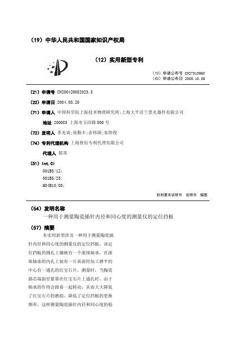
(19)中华人民共和国国家知识产权局(12)实用新型专利(10)申请公布号CN2731396Y(43)申请公布日2005.10.05(21)申请号CN200420082023.3(22)申请日2004.08.20(71)申请人中国科学院上海技术物理研究所;上海大平洋兰登光器件有限公司地址200083 上海市玉田路500号(72)发明人李光南;张勤丰;余伟国;朱伟俊(74)专利代理机构上海智信专利代理有限公司代理人郭英(51)Int.CIG01B5/12;G01B5/25;H04B10/08;权利要求说明书说明书幅图(54)发明名称一种用于测量陶瓷插针内径和同心度的测量仪的定位挡板(57)摘要本实用新型涉及一种用于测量陶瓷插针内径和同心度的测量仪的定位挡板,该定位挡板的圆孔上镶嵌有一个滚珠轴承,在滚珠轴承的内孔上装有一片表面经加工磨平的中心有一通孔的红宝石片。
测量时,当陶瓷插芯端面径紧靠在红宝石片上通孔时,由于轴承的作用会跟着一起转动,从而大大降低了红宝石片的磨损,降低了定位挡板的更换频率,这样测量陶瓷插针内径和同心度的稳定性和重复性也大大提高。
法律状态法律状态公告日法律状态信息法律状态2005-10-05授权授权2007-10-10专利权的终止未缴年费专利权终止专利权的终止未缴年费专利权终止权利要求说明书一种用于测量陶瓷插针内径和同心度的测量仪的定位挡板的权利要求说明书内容是....请下载后查看说明书一种用于测量陶瓷插针内径和同心度的测量仪的定位挡板的说明书内容是....请下载后查看。
1000H线材测试仪器检校手册说明书
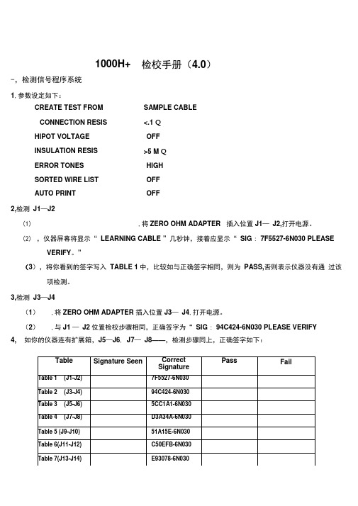
1000H+ 检校手册(4.0)-,检测信号程序系统1,参数设定如下:CREATE TEST FROM SAMPLE CABLECONNECTION RESIS <.1 QHIPOT VOLTAGE OFFINSULATION RESIS >5 M QERROR TONES HIGHSORTED WIRE LIST OFFAUTO PRINT OFF2,检测J1—J2(1) ,将ZERO OHM ADAPTER 插入位置J1—J2,打开电源。
(2),仪器屏幕将显示“ LEARNING CABLE ”几秒钟,接着应显示“ SIG : 7F5527-6N030 PLEASEVERIFY。
”(3),将你看到的签字写入TABLE 1中,比较如与正确签字相同,则为PASS,否则表示仪器没有通过该项检测。
3,检测J3—J4(1),将ZERO OHM ADAPTER 插入位置J3—J4,打开电源。
(2),与J1 —J2位置检校步骤相同,正确签字为“ SIG : 94C424-6N030 PLEASE VERIFY4, 如你的仪器连有扩展箱,J5—J6, J7—J8——,检测步骤同上,正确签字如下:2, 将 1000H+ RESISTANCE ADAPTER 插入 J1—J2 位置。
3, 打开电源,显示:LEARNED CABLE RESISTANCE ERROR 4, 按 DISPLAY/PRINT 键,显示:J1B002 J1B0049.8Q5, 将显示的电阻值写入TABLE 9中,比较如介于最小值(MIN)与最大值(MAX)之间,则PASS 6, 按DISPLAY/PRINT 键,将显示的电阻写入 TABLE 10中,与5操作相同。
7, 继续按DISPLAY/PRINT 键,重复上述操作:1,参数设定如下:CREATE TEST FROM SAMPLE CONNECTION RESIS v. 1 Q HIPOT VOLTAGE OFF INSULATION RESIS >5M Q ERROR TONES HIGH SORTED WIRE LIST OFF COUNT ALL CABLESOFF二,检测电阻测量系统AUTO PRINT OFFCABLE三.检测电阻边界系统(1)1. 按下MEM 键,显示签字SIG : 577188-6N030.PLEASE VERIFY.将屏幕显示写入TABLE 142. 再按MEM 键,显示签字SIG : 577188-6N030.INSULATION SHORT.3. 按DISPLAY/PRINT 键.4. 将你看到的NCJ***.写入TABLE 15,正确值为NCJ1B016,与正确一致则PASS5.6. 再按DISPLAY/PRINT 键■应显示SIG:577188-6N030 INSULATION SHORT。
FC-1000使用指南

FC-1000 使用指南FC-1000是拓普康公司2003年6月推出的新一代测量手簿(控制器),该手簿采用目前世界上最先进的技术,专为野外测量人员设计。
FC-1000测量手簿提供了其它同类产品所不能提供的功能:●可移动闪存卡。
●2个com端口。
●USB端口。
●可移动的充电锂电池。
●具有300MIPS超快运算速度的Hitachi SH4微处理器162.2MHz。
80690172.doc 180690172.doc 2FC-1000部件说明FC-1000按键的补充说明1.FC-1000采用WinCE的标准操作。
2.[RESET]键(冷启动)在FC-1000电池盖内,只需用笔按下,保持数秒钟,即可将系统重置于出厂设置状态。
注意:此时TopSURV软件在WinCE桌面上的图标将会丢失,需要重新安装。
冷启动后,将会提示要校准笔光标,用笔按住十字并保持数秒钟即可,当校准了全部五个十字符号,按[ ENT]即可。
3.如果在FC-1000的WinCE桌面找不到TopSURV图标,可以用“Start/Program/Windows Explorer”,查找“Storage Card/TPS/TopSURV/TopSURV.exe”,双击运行该程序即可。
4.热启动需要同时按下[Shift]+[Func]+[ESC]三键保持数秒钟。
此时将会重新启动WinCE。
5.[Power]键处于面板的正面,用于开关机。
6.[Alt]键相当于鼠标的左右键切换。
7.[Func]键用于调出按键第二功能。
8.[Del]键用于删除所选目标。
9.[B.S]键用于删除最后的一个字符。
10.[Shift]键用于切换大小写。
并可用于连续选中多个目标。
11.[ENT]=[Enter],[Tab]、[ESC]、[Del]和[Alt]键的功能同PC机。
80690172.doc 3。
真正RMS双显示线路zens kun笼头计量仪 温度计说明书

Overload Protection 600V RMS
Overload Protection 600V RMS Overload Protection 600V RMS Overload Protection 600V RMS
Overload Protection 30V RMS
40kΩ
10Ω
± (1.0% +4 dgts)
400kΩ
100Ω
4MΩ
1kΩ
40MΩ
10kΩ
± (2.0% +4 dgts)
Overload Protection 2000µA/600V RMS Overload Protection 2000µA/600V RMS Overload Protection 2000µA/600V RMS Overload Protection 750V RMS
DC Volts
Range
Resolution Accuracy
400mV
0.1mV
4V
1mV
± (0.5% +4 dgts)
40V
10mV
400V
0.1V
1000V
1V
± (0.8% + 10 dgts)
Resistance
Range
Resolution Accuracy
400Ω
100mΩ
4kΩ
1Ω
• True RMS
• 750V AC • 1000V DC • 400A AC • Temperature range:
-22°F to 752°F (-30°C to 400°C)
QCR-1000A

CSA-1000炉前铁液管理仪(键盘、触摸屏两用)特别提示(1)供电电源为交流220V,50Hz,请勿插错电源!(2)保证电源良好接地。
(3)电源开关切忌来回拨动。
(4)关机时请从菜单栏-点击“退出”正常关机,勿直接关闭电源,程序退出后将提示“请关闭电源”,此时再关闭电源!1界面说明图1总显示界面显示界面由7个部分组成,如图2所示:图2 系统显示界面示意图1.1菜单说明图3 菜单展示图3显示了菜单完全打开的情况。
点击“文件”将出现“打开数据”子菜单,点击“打开数据”将弹出“数据中心”对话框。
用户可以在“数据中心”对话框中对以前保存的数据进行浏览、查询、删除等操作,具体内容请参见“‘数据中心’对话框的使用”一节。
点击“功能”将出现以“目标、重量、维护、其它参数”为内容的子菜单,其中“维护”下还有“改变目标材质内容、设定检量线、改变日期”的二级子菜单。
点击“目标”将弹出“改变目标材质”对话框,用户可以在这里改变下次检测的铁水牌号,具体操作请参见“‘改变目标材质’对话框的使用”一节。
点击“重量”将出现“重量”对话框,用户可以在这里改变样品铁水所在熔炉的铁水总重量,具体操作参见“‘重量’对话框的使用”一节。
点击“改变目标材质内容”将弹出“系统维护—改变目标材质内容”对话框,用户可以在这里改变标准材质的具体参数,具体操作参见“‘系统维护—改变目标材质内容’对话框的使用”一节。
点击“设定检量线”将弹出“系统—改变检量线参数”对话框,用户可以在这里设定8条检量线的参数,具体操作参见“‘系统—改变检量线参数’对话框的使用”一节。
点击“改变日期”将弹出“设定日期时间对话框”,用户可以在这里设定系统的时间,具体操作参见“‘设定日期日期’对话框的使用”一节。
点击“厂家设定”将出现“登陆”子菜单,点击“登陆”后将弹出登陆对话框,输入密码后可以进行系统维护。
这项操作仅限于厂家的技术人员。
点击“退出”将结束程序的运行。
1.2 温度显示说明图4 温度显示温度显示显示分为“当前温度”和“最高温度”两项。
- 1、下载文档前请自行甄别文档内容的完整性,平台不提供额外的编辑、内容补充、找答案等附加服务。
- 2、"仅部分预览"的文档,不可在线预览部分如存在完整性等问题,可反馈申请退款(可完整预览的文档不适用该条件!)。
- 3、如文档侵犯您的权益,请联系客服反馈,我们会尽快为您处理(人工客服工作时间:9:00-18:30)。
Norland Centroc1000Operating ManualVer 1.61Ferrule Eccentricity Measurement Ferrule Concentricity Measurement Ferrule Cylindricity Measurement Point to Point MeasurementInsertion Loss CalculationVisual ExaminationNorland Products Incorporated Phone: 609-395-1966Fax: 609-395-90062540 Route 130 Building 100, Cranbury NJUSA -08512INDEXSection No. Section Name Page1. Introduction 32. General description 33. Equipment Setup 44. Software Setup 55. Centroc1000 Main Screen136. Centroc Menus146.1 File Menu146.2 Tools Menu:146.3 Display Menu:156.4 Options Menu:196.5 About Menu:237. Changing Mount Fixtures238. Measuring Eccentricity259. Visual Examination 2610. Service Information2611. Specifications2712. Appendix A – Theory2812.1 Insertion Loss Estimation2912.2 Criteria for reference connectors291. IntroductionThe Centroc1000 unit, for noncontact measuring of ferrule endface geometry, is part of Norland Product’s range of measuring equipment for Optical Cable Assembly shops.The unit complies with:IEC 61300-2-41ISO 2538IEC 61300-3-18 IEC 61300-3-24 IEC 61300-3-262. General descriptionThe Centroc1000 is a special designed auto-focusing microscope with a precision chuck for ∅ 2.500 mm or for ∅ 1.250-mm fiber optic ferrules.In Order to achieve maximum accuracy the magnification in model 1000 is 900 X on a 17’’ monitor.3. Equipment Setup• Connect the "Centroc1000" and the PC using the cable supplied (9-pin female to Centroc1000 and 9-pin male to the frame grabber card interface at the PC).• The Centroc1000 uses the USB interface for motor and lighting control. Connect the USB cable to Centroc1000 and insert the other end into one of the USB ports. Ifplugging into that port for the first time, the following setup procedure may be required. • Connect monitor, mouse, printer and keyboard to the PC.• Connect the Printer and the Personal Computer to AC- power mains.• Verify the computer monitor Screen Area is set to “1024x768” with Colors set to “True Color (24 bit)”4. Software SetupThe Centroc1000 system comes with any required software already installed onto its associated computer. The Centroc1000 application is designed to operate underWindows 2000 Pro or Windows XP Pro. The minimum requirement for PC: Intel P III 800 MHz.In the event the Centroc1000 software needs to be reinstalled, it must be installed in the following order:4.1 Euresys drivers for the Picolo frame-grabber.4.2 Centroc1000 measurement application.If updating just the Centroc1000 application, only step 2 need be performed.Check for any new versions on the Norland Products web-site4.1 Euresys drivers for Picolo frame-grabber:Installation from the Euresys CD:a. Place the CD, and select INSTALL to install the softwareb. Select Run-time and select evision and Multicam for Picolo and Click Nextc. Click NEXT on the following screend. Select Easy Grab, Drivers, ActiveX and Click NEXT on the following screen.e. Leave the default and click NEXT on the following screenf. After successful installation the click ok on the following message andclick Quit from the initial installation screen to close the screen.4.2 Centroc1000 Software Installation:Installation from the Centroc1000 CD:a. Insert the CD to install the software. Click Next to the following displayb. Choose “I accept” and click Nextc. Enter the customer Information (or accept the default) and click Next.d. Click Next to start the installatione. Click Finish to end the installation.Configuring the Centroc1000 USB Interface:a. Plug in the USB cable:Plug in one end of the USB cable to the Centroc1000 instrument and its other end into one of the computer’s USB ports. Once the cable is plugged in, thefollowing message will be shown at the bottom of the screen.b. Install the new USB driver ELEKTOR:The following screen prompts the user to install the new drivers. Choose “Install the software automatically” and click next.Searching for the necessary filesClick Next after it found the filesClick “Continue Anyway”Click Finish to complete. Appearance of the following message will indicate that the installation has been successful:5. Centroc1000 Main ScreenRun the application, the following main screen appears.MenubarImage: Live image from the camera.Menu bar: Collection of pull-down menus of various program functionsand options.Align Ferrule: After inserting a ferrule, click this button to bring its end facefully into the fixture before starting a measurement.Run Test: Click this button to calculate the eccentricity or concentricityfor the ferrule. Ferrule rotates automatically. While rotating,several measurements are taken at each rotation point. Thepoints along with eccentricity values are displayed on aseparate “Results” window. Before clicking “Run test” makesure to click the Focus and Align Ferrule buttons.Eject: Use this option to remove the ferrule from the mount.Focus: Click to activate focusing.Tuning On/Off: Status of Tuning the ferrule for marking is displayed. “TuningOn” for a measurement means rotate the ferrule, so the endferrule eccentricity or concentricity is aligned at 12 o’clockposition at the end of the measurement. “Tuning On” isrequired for the ferrules, which need marking. “Tuning Off”for normal measurement. To select Tuning On or Off, use the“Perform tuning at the end of measurement” option fromOptions/Menu from tool bar.Back light: Click ‘+’ or ‘-‘ buttons to adjust the level of illumination. 6. Centroc Menus6.1. File Menu :Exit:To close the application.6.2. Tools Menu:Change Mount On/Off:This option, when selected, will activate an Image circle template and on-screen instructions that assist the user in changing the mounting fixture. (SeeSection 7.Changing Mount Fixtures)Inspection Mode On/Off:Choose this option to increase illumination on the connector endface. Whenselected, use additional set of buttons (“+/-“) to make smaller increases ordecreases to the illumination level as needed.6.3 Display Menu:6.3.1 Statistics:When selected, a separate form with statistical report of the results history is displayed (see figure below).At top left in the above figure, a table lists the results from all storedmeasurements. Statistical displays from a subset of those measurements are at top center as well as the two bottom displays. The amount ofmeasurements used in the statistical displays can be selected by the operator (by entering how many of the last measurements into the top center box).From the graph at top right, an estimation of a particular ferrule’s worst-case insertion loss can be made using the its eccentricity result. See the Theory Section in Appendix A for more information.a. File Menu:File menu from the Statistics display contains Data, Print, & Exitchoices.i. Data:On choosing data the following options are showed• Clear List: To clear results from the form.• Restore Last list: To restore last cleared results.ii.Print:On choosing Print the following options are shown to the user • Print Form : Print the current form.• 2. Print all records: Print all the stored results fromthe database.iii. Print (sort) : This will show Data Record Selectionform to print only data from a particular date range orwith a particular Product ID.Print: After choosing the dates or Product IDclick print to print the data.Exit: Click to exit from this form.6.3.2 Last Results:This display shows a graphical representation of the eccentricity or concentricity measurements as well as the following measured or calculated quantities from the most recent scan.Note: For the first 5 items either Eccentricity or Concentricity values will be shown depending on the Measurement Type (as chosen in Options/Menu before measurement).a. Eccentricity /Start: The first measured eccentricity value.b. Eccentricity /End: The last measured eccentricity value.c. Eccentricity /Fitted: The mean Eccentricity value for the ferrulearrived at by means of a least-squares circle fit to all the eccentricityvalues.d. Maximum Eccentricity: Max eccentricity value measured.e. Minimum Eccentricity: Min eccentricity value measured.f. Ferrule Cylindricity: Cylindricity of the ferrule. A measure of theferrule’s deviation from a perfect cylindrical shape.g. Cavity Diameter: Fiber hole diameter for the ferrule measured.h. Calculated Insertion Loss: Theoretical Insertion loss based on fittedEccentricity.i. Ferrule Type: Type of the ferrule from the Options/ Menuj. End Angle: Angle at the last measured point- red circle.Note: When Tuning is on, the End Angle is the angle at 12 o’ clockposition which is 0 degrees.k. Product ID: ID entered before the measurementl. Operator: Operator entered in the Options/Menum. Centroc 1000 model sn: Serial number of the Centroc1000 modelPress [Print] to print the current screen.Press [Next] to return to the start screen to measure the next product.Press [Stats] to see statistical presentation of results.Press [Excel Viewer] to view the saved scan results in Microsoft Excel. The text file viewed can be selected or changed in theOptions/Menu under “Save Results to” section.Excel Viewing the Text File:6.4 Options Menu:Adjust the different parameters as required per connector specification and as desired by the operator.Explanation of the Options Menu fields:SerialNumber Picolo: Picolo frame grabber serial number from the Board. SerialNumber Centroc: Centroc1000 serial numberCalibration Factor: The magnification calibration factor entered at the factory forthe unit. It should match the value marked on its rear panel. Ifthere is any question about the correctness of this value orneed to recalibrate, contact Norland Products TechnicalSupport for assistance.Ferrule Type: Choose the appropriate selection for the sample being tested.Pass /Fail Criteria: Enter desired Min and Max limits for the average Eccentricity(“Ecc/Fitted”) or Concentricity depending on Measurement Type choice. At measurement completion the result will be compared against these limits and displayed on Red (Fail) or Green(Pass) background.Perform Tuning at the end of measurement: Select this option to rotate the ferrule at the end of the measurement, so the ferrule end Eccentricity or Concentricity is aligned at 12 o’clock position. The status of Tuning is displayed on the main screen below the live image.Measurement Type: Depending on the measurement type chosen the scan results will be displayed on Results screen and Statistics screen as shown below.For Eccentricity:For Concentricity:Show Maximum/Minimum: Maximum and Minimum Eccentricity values will only be shown on the Results screen if this option is checked.Product ID: Information for Product IDa. Prompt For Input Select this option if it is desired to be prompted for aProduct ID before each new measurement. At the time of measurement, thefollowing prompt will be presented. After entering an ID (or accepting thevalue already there), click OK to continue with the measurement or Cancel to exit from the measurement.b. Auto Increment: Check this option if the ID to be incremented for nextmeasurement.Save Results To: Choose/enter the ASCII text filename and location where measurement data will be stored. This file can be later imported into other programs like “Microsoft Excel” for additional processing and can be viewed through Results screen.Operator: Select this option if it is desired to include an Operator name among the displayed and stored results of a measurement.Explanation of the Options Menu buttons:Defaults: Load the factory defined defaults.Note: Different defaults will be loaded depending on choice for FerruleType.Cancel: Close the form without saving any changes.Apply: Save any changes and close the form.Note: It is possible to select and then save (using this Apply button) two completely different configurations of options; one for the SM and another for MM ferrule type choices. Then it is easy to switch from one configuration to the other simply by changing Ferrule Type selection.6.5 About Menu:Click Help/About to show the software product information.7. Changing Mount FixturesThis procedure should be followed when the mounting fixture needs to be changedto a type for different diameter ferrule, for example from 1.25 to 2.50 mm diameter.• Remove front main-panel.• Remove holding-down spring from driving-lever assembly.• Remove driving belt from driving-lever with tweezers and place it on a clean piece of paper. (NOTE: Avoid touching the belt by hand at all times!)• Press “Align Ferrule” button to rotate motor shaft, until the setscrew on rightmost pulley is visible.• Using M1 Hex Key, loosen setscrew of pulley on motor shaft by ½ turn counter clockwise.• Using both hands, pull driving-lever assembly towards operator, and allow pulley on motor shaft to gently slide out along motor shaft.• Using M3 Hex Key, replace v-groove mount by new mount.• Hold driving-lever assembly with both hands. Gently slide its rightmost pulley back onto the motor shaft until assembly stops at front surface of brass disk on v-groovemount.• Using M1 Hex Key, tighten setscrew of pulley on motor shaft.• Replace driving belt to driving lever with tweezers. (No hand touch on belt is allowed.)• Replace holding-down spring on driving-lever assembly.• Insert a testing ferrule of appropriate size into v-groove mount.• If needed, perform manual focusing of ferrule image by turning front-bottom knob. • If needed, perform manual centering of ferrule image by turning micrometers at both sides behind v-groove mount.• Replace front main-panel and press Close to resume measurements.Mounting heads and Driving Belts8.Measuring Eccentricity• Go to the measurement screen (as pictured above). If the current display is the Statistics screen, click EXIT. If, instead, it is the Results screen, click NEXT. • Set the required options in Options screen.• Open the mounting fixture by lifting the lever to the left of the fixture.• Place the ferrule into the fixture V-groove, let the lever down to hold the ferrule in place.• Click Align Ferrule before measuring• Click Run Test. The ferrule will rotate automatically. While rotating, several measurements are taken at each rotation point. The points along with eccentricity values are displayed on a separate “Results” window. See Last Results insection 6.39. Visual ExaminationExample of SM image on a Centroc1000Length measurementPlanar dimensions on the ferrule such as ferrule diameter, adhesive ring thickness,and scratch width can be checked using the live Image and a mouse. By clicking the left mouse button at two points on the Image, the distance between those two points can be measured.Additional ToolsA variety of additional tools can be found by clicking the right mouse button whilethe cursor is on the live Image. Features such as zooming, panning, and Imagecopying can be selected and used as part of the visual examination process.10. Service InformationItem DescriptionAccessories Std Fixture for 1.25mm ferrules (LC and MU connectors)Std Fixture for 1.60mm ferrules (supports M29504/4 and M29504/5 connectors)Std Fixture for 2.00mm ferrules (supports M29504/14 and M29504/15 connectors)Std Fixture for 2.50mm ferrules (supports SC and FC connectors) 20060110 20060111 20060112 2006011311. SpecificationsPower Requirements +12 V DC (supplied by the PC via the Frame Grabber connector) Supported Fiber types Suitable for most SM and MM fiber connector ferrules(Supports Maximum fiber diameter up to 140 (µm)) Temperature 10°-40° C Operating5°-55° C StorageHumidity RH Maximum 90% no condensationWavelength (LED) λ 475 nmMeasurement uncertainty 0.1 µm (Eccentricity), 0.2 µm (Concentricity)Minimum PC requirement Operating system Intel P4 or AMD Athlon Preferably +2 GHz .1 free PCI slot for Picolo frame-grabber. Windows 2000 or XP ProStandards reference IEC 61300-2-41IEC 61300-3-18IEC 61300-3-24IEC 61300-3-26ISO 2538We continuously upgrade software and documentation.Check on for the latest versions.12. A ppendix A – Theory12.1 Insertion Loss EstimationThe amount of insertion loss contributed by the ferrule component of a connector can be estimated by noting the difference between that ferrule’s center and its fiber-hole center. This difference is supplied by the Centroc1000 as the Eccentricity measurement. Assuming all else is ideal once a connector is assembled using this ferrule, the estimated insertion loss (measured against a concentric reference connector) can be read from the following figure using that Eccentricity result.Loss (dB)Ecc. (µm)0.00 0.000.10 0.000.20 0.010.30 0.020.40 0.030.50 0.050.60 0.080.70 0.110.80 0.140.90 0.171.00 0.211.10 0.261.20 0.311.30 0.361.40 0.421.50 0.481.60 0.551.70 0.621.80 0.691.90 0.772.00 0.86For not-tuned connectors (with angle of eccentricity anywhere within 180°of its key), the worst case random loss for a population of product can be estimated by adding the two highest eccentricities in a population.For example:Eccentricities: Connector_x = 0.8 µm, Connector_y = 0.9 µm.(ecc-x + ecc-y) = ecc-tot or (0.8 +0.9) = 1.7 µmFrom the graph: 1.7 µm eccentricity results in 0.62 dB worst case loss.For tuned connectors (which, through tuning, will have an angle of eccentricity within 45°of its key).The worst case random loss for a population of tuned product can be estimated by adding the two highest eccentricities in a population and dividing that sum by 1.414. For example:(ecc-x + ecc-y) /1.4 = ecc-tot or (0.8 +0.9)/1.414 = 1.2 µmFrom the graph: 1.2 µm eccentricity results in 0.31 dB worst case loss.12.2 Criteria for reference connectorsA connector is suitable for reference purposes if the requirements for reference products as presented in the relevant specification or related IEC documents are met.For the case of a user having their own purchasing specification, use the criteria for reference components from this document. If no specification for reference is given, a reference can be selected from the table below.The maximum allowable eccentricity for a batch of connectors is dependent not only on the connector under test, but also on the reference connector used….Example:If the Loss Specification is 0.20 dB according to IEC method 7 (first column intable), then the maximum allowed (total) eccentricity as 0.95 µm. This is the sum of the maximum eccentricity of the connector under test and the maximum eccentricity of the reference connector (from the table).This example shows that a reference connector should be selected with an eccentricity value as low as possible. Careful selection of a reference connector with the lowest possible value for eccentricity results in best yield (more connectors that will be considered to have acceptable eccentricity) in the final loss measurement.Single Mode connectors.Loss against concentric reference connector.(IEC method 7) Maximum lossin the field2%Maximum EccentricityReference connectorMaximum eccentricityof connector under test0.10 dB 0.40 dB 0.10 µm 0.58µm0.20 dB 0.77 dB 0.20 µm 0.75µm0.30 dB 1.16 dB 0.20 µm 0.98µm0.40 dB 1.75 dB 0.25 µm 1.11µm0.50 dB 2.10 dB 0.30 µm 1.24µm。
