真善美包缝机1200d选配件中文说明书
1200微机继电保护测试仪说明书
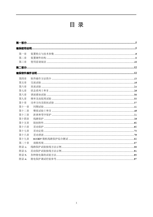
目录第一部分 (5)继保使用说明 (5)第一章装置特点与技术参数 (6)第二章装置硬件结构 (8)第三章使用前请阅读 (10)第二部分 (12)继保软件操作说明 (12)第四章软件操作方法简介 (13)第五章交流试验 (16)第六章直流试验 (24)第七章状态系列Ⅰ和Ⅱ (26)第八章谐波叠加试验 (30)第九章频率及高低周试验 (33)第十章功率方向及阻抗试验 (37)第十一章同期试验 (41)第十二章整组试验Ⅰ和Ⅱ (46)第十三章距离和零序保护 (51)第十四章线路保护 (56)第十五章阻抗特性 (62)第十六章差动保护 (65)第十七章差动定值 (73)第十八章差动谐波 (79)第十九章6-35KV微机线路保护综合测试 (82)第二十章故障再现 (87)附录1:线路保护试验接线方法示例 (88)附录2:差动保护试验接线方法示例 (91)附录3:各种继电器的试验方法 (93)附录4:继电保护调试经验参考 (97)继电保护试验项目索引本索引旨在引导试验人员:各种继保装置的试验可以通过―继保‖系列软件的哪些模块完成。
继电器试验:微机保护试验:第一部分继保使用说明第一章装置特点与技术参数第一节主要特点◆电压电流输出灵活组合输出达6相电压6相电流,可任意组合实现常规4相电压3相电流型、6相电压型、6相电流型,以及12相型输出模式,既可兼容传统的各种试验方式,也可方便地进行三相变压器差动试验和厂用电快切和备自投试验。
◆操作方式装置直接外接笔记本电脑或台式机进行操作,方便快捷,性能稳定。
◆新型高保真线性功放输出端一直坚持采用高保真、高可靠性模块式线性功放,而非开关型功放,性能卓越。
不会对试验现场产生高、中频干扰,而且保证了从大电流到微小电流全程都波形平滑精度优良。
◆高性能主机输出部分采用DSP控制,运算速度快,实时数字信号处理能力强,传输频带宽,控制高分辨率D/A转换。
输出波形精度高,失真小线性好。
工业缝纫机伺服控制器用户手册说明书

工业缝纫机伺服控制器用户手册前言注意: 使用前请详细阅读本用户手册及所搭配的缝制设备说明书,配合正确使用,并须由接受过专业培训的人员来安装或操作。
本产品仅适用于指定范围的缝制设备,请勿移做其他用途。
本公司拥有对此用户手册的最终解释权。
使用中若存有任何疑问或对我们的产品及服务有任何意见或建议,请随时与我们联系。
安全说明1)安装和调试前,请仔细认真地阅读本手册。
2)本手册中标有符号之处为安全注意点,必须特别注意并严格遵守,以免造成不必要的损害。
3)本产品须由受过专业培训的人员来安装或操作。
4)确保电源安全接地并符合产品铭牌上标示的电压范围及技术要求。
第 1 页共 8 页第 2 页 共 8 页5) 接通电源开关时,请把脚离开脚踏板。
6)在进行以下操作时,必须先断开系统电源:■ 安装机器时;■ 在控制箱上插拔任何连接插头时; ■ 穿针线,换机针及翻抬机头时; ■ 机器休息不用及修理或调整时。
7) 拧紧所有紧固件,以防止缝制作业时产生振动或停针位置错位等异 常现象。
8) 每次关闭控制系统后再次启动,应相隔30秒以上。
9) 设置系统控制参数或进行保养修理工作应由受过相关培训的专业人 员来完成。
10) 维修所用的所有零部件,必须由本公司提供或认可,方能使用。
11) 接地线的安装(特别注意)。
注意:安装控制器时必须正确接地,否则将导致控制器无法正常工作,更严重的可能会被电击(详见安装章节)。
1. 产品介绍 1.1 概述此系列工业缝纫机数控交流伺服系统,电机与控制器分体吊装,使配置组合灵活方便,电机与控制器可按需搭配,实现多种缝纫机对功率、速度等的配套要求;安装简易、调整便捷、力矩大、体积小、噪音低、效率高(省电!);采用开关电源供电,使其具有更宽的电压适配范围;电磁铁侧面接插,使连接更可靠,避免油渍污染引起的控制器故障;优化交流伺服电机控制策略,使转速控制精度高,停针速度快;专利设计的吊装方式使安装更简捷,整体震动降至最低,系统运行更平稳;具有电磁铁回路短路保护功能,防止错误接线损坏控制器。
真善美包缝机1200d选配件中文说明书

1200D选购配件 使用说明书橡筋打褶压脚(C)和橡筋附件橡筋打褶压脚不仅用于没有橡筋的较硬布料,更适合用于制作你自己的饰带。
三个附件(7.5mm、10mm、13mm)分别用来将扁平的橡筋直接缝纫在布料上。
调节螺丝来控制加在打褶用的橡筋上的压力。
安装橡筋打褶压脚根据橡筋的宽度选用合适的橡筋附件。
拷边机以三线或四线快速地将橡筋缝纫在布料上。
1. 选择缝纫程序:3线宽或4线。
穿线,并按机器上或说明书的说明设置机器。
线迹宽度调到最宽。
装上橡筋打褶压脚。
2. 将橡筋附件“A”安装在橡筋打褶压脚上。
参考图1。
3. 拧松调节螺丝“B”,将橡筋放入橡筋附件的槽中。
将橡筋从压脚的下面拉到压脚的后面。
拧紧螺丝“B”,设置打褶量。
参考图2。
4. 导板“C”定位,使橡筋在针板的边上,紧贴着割刀。
5. 将机针放下,插入布料。
放下压脚。
6. 用手转动手轮缝纫开始的两针。
调节橡筋附件尝试缝纫,并且检查割刀只割到布料,不割到橡筋。
以中速缝纫。
参考图3 。
注意:如果你使用橡筋蕾丝,将蕾丝的扇贝花边插到橡筋附件的左边。
高效智能,导布器正好折出6mm的边。
同时它还卷边,并缝上放在下面的蕾丝或边饰。
和绷缝压脚(M)一起使用。
用绷缝压脚生成蕾丝边的卷边 绷缝线迹是专业的卷边方法。
蕾丝导布器折叠出6mm的边。
然后有效地在折边上缝纫绷缝线迹。
缝纫扁平的卷边时这个卷边方法最合适。
蕾丝送入后线迹就缝纫上去。
1. 选择缝纫程序:三针绷缝,绷缝宽或绷缝。
按机器上的提示设置机器并穿线。
装上绷缝压脚。
2. 折出或用手指压出大约5cm布料,下面6mm形成卷边。
3. 导布器装在压脚前,先将折边放入H-2导布器。
参考图1。
4. 布料放在压脚下面,机针插入布料。
放下压脚。
将导布器H-2卡在压脚上。
参考图2。
5. 用手转动手轮缝纫开始的两针。
左手握住布料,右手折出卷边,并继续缝纫。
布料要均匀地导入。
参考图3。
均匀的边。
只要简单的将布料插入导布器,导布器自动折出并生成2.5cm的边。
SND中文说明书
前言
感谢您选用“LNTECH(莱恩)”牌光电保护装置! 光电保护装置又称为光电保护器、安全光幕、安全光栅等,本说明书中仅使用“光电保 护装置”这一名称。
光电保护装置主要用于机械加工设备、危险工作区域,防止机械设备对操作者的伤害 和误入危险区域造成的人身伤害,保护人身安全。
本装置仅保护发光器与受光器(SNC/D/E系列)之间的矩形光幕区域。如果其安装位置 不正确,或不按说明书与相关安全作业条例操作,或机床执行机构故障,都可能使其无法 起到保护作用。因此,安装本装置之前,请仔细阅读说明书,充分理解有关事项,尤其是 说明书中标出的“警告”、“注意”等内容;在使用过程中,请正确理解光电保护装置的 工作性能,严格按照本说明书所提出的要求,制定相应的安全作业条例。
本说明书仅介绍光电保护装置在压力机上的应用,其它方面的应用,可参照本说明 书。
本说明书内容解释权归山东莱恩光电科技有限公司,阅读或使用本说明书时,如有不明 之处,请与本公司联系。
禁止事项: 1) 禁止擅自复印、转载本使用说明书的部分或全部内容。 2) 关于本使用说明书的内容,将来可能因装置改良等原因而进行修改,恕
2 基本介绍
2 . 1 术 语 …………………………………………………………………………………………… 3 2 . 2 用 途 …………………………………………………………………………………………… 4 2 . 3 特 点 …………………………………………………………………………………………… 4 2.4 检测精度与光轴间距的关系…………………………………………………………………4 2 . 5 技 术 参 数 ……………………………………………………………………………………… 5 2 . 6 规 格 说 明 ……………………………………………………………………………………… 6 2.7 工作示意图……………………………………………………………………………………6 2.8 认证标志及技术标牌…………………………………………………………………………7
包缝机控制器使用说明
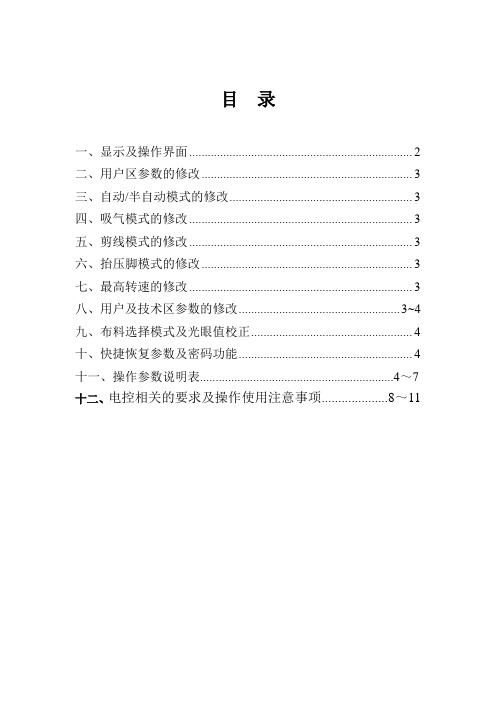
目录一、显示及操作界面 (2)二、用户区参数的修改 (3)三、自动/半自动模式的修改 (3)四、吸气模式的修改 (3)五、剪线模式的修改 (3)六、抬压脚模式的修改 (3)七、最高转速的修改 (3)八、用户及技术区参数的修改.................................................... 3~4九、布料选择模式及光眼值校正 (4)十、快捷恢复参数及密码功能 (4)十一、操作参数说明表..............................................................4~7 十二、电控相关的要求及操作使用注意事项....................8~11一、显示及操作界面序号图标说明备注1 用户参数设定键点按为选择参数的快揵;长按为设值参数的快揵2 左移键左移动光标3 技术参数设定键/速度设定键点按为选择参数的快揵;长按为设值参数的快揵4 上移键参数项加和参数值加5 确认键修改参数值确认6 下移键参数项减和参数值减7 右移键右移动光标8 LED亮度调整键点按为选择参数的快揵;9 模式转换键点按为选择参数的快揵10 剪线模式调整键点按为选择参数的快揵;长按为设值参数的快揵11 吸气模式调整键点按为选择参数的快揵;长按为设值参数的快揵12 料选择快捷键点按为选择布料的快揵;长按为查看或手动校正光眼值的快揵13 抬压脚模式调整键点按为选择参数的快揵;长按为设值参数的快揵二、用户区参数的修改当用户长按下键时,进入用户参数模式;通过按键、修改对应的参数号,通过按键、修改对应的参数值,按键确认。
显示相应的参数序号及参数内容;当用户点按下键,退回到待机界面。
三、自动/半自动模式的修改当用户点按下键时,进入人工、半自动、自由缝和全自动模式的修改状态,不断按键时,模式循环如以下四种状态:人工、半自动、自由缝和全自动。
四、吸气模式的修改当用户点按下键时,即可修改吸气模式。
工业包缝机使用说明书
使用说明书User Guide工业包缝机Industrial sewing machine感谢您购买本公司的产品。
为了您的使用安全,请您在使用之前一定仔细阅读本使用说明书。
Thank you for purchasing our products.For your use safety,please must read the instruction manual before use.●前言感谢你选购本产品,为了你更好的使用本产品,在安装与调试前,请仔细阅读本操作说明及所搭配的缝纫机设备使用说明书,并由专业人员来安装与调试。
注意:使用中若出现任何疑问或对我们的产品及服务有任何的意见或建议,请随时与我们联系;本公司拥有对此手册的最终解释权。
本操作指南的用途:本操作指南基于用户的要求提供相关指导信息;这些信息涉及设备及其他使用场合、运输、安装、使用和维护;本操作指南主要面向用户和技术人员。
●安全说明1.请确保在插上插头通电以前,控制器开关按钮为关闭;2.请确保在开关按钮打开前已将线插好,否则会提示出错;3.无专业人员在场,请勿拆开控制器,以免造成意外;4.请确保可靠接地,避免触电;警告:控制器内部及接口线头均带强电,切勿触碰,以免触电!12◆接口插头的连接将脚踏板及机头的各连接插头安插到控制器后面对应的插座上。
连接好,请检查插头是否插牢。
◆操作面板说明图标功能说明1:工作模式下,切换上、下停针位;2:参数模式下,作参数设置。
1:工作模式下,开关LED 灯;2:参数模式下,作参数保存。
1:工作模式下,调节电机转速;2:参数模式下,作参数的选择及调整。
●参数调整及示例1.1控制器操作面板显示方式为四位共阴数码管。
待机界面下,按“+”、“-”键,可以调节即时转速。
1.2待机界面下,按“P”键,上针位指示灯亮时,为上停针;下停针指示灯亮时,为下停针;指示灯不亮,关闭停针功能。
1.3待机界面下,按“S”键,可以打开和关闭机头灯。
1200产品说明书(正式)
MG500/1200-WD滚筒式采煤机产品说明书操作人员必须进行相应的煤矿安全规程培训使用者在使用前必须认真阅读本产品说明书太原矿山机器集团有限公司2007年2月(本产品执行MT/T81、MT/T82、Q/140000TK02-2007标准的规定)目录第一章整机概述 (1)1. 机器型号 (1)2. 机器用途 (1)3. 采煤机的组成 (1)4. 采煤机的特点 (1)5. 采煤机的技术特征 (4)第二章摇臂 (6)1. 摇臂的作用 (6)2. 规格与性能 (6)3. 机器的外形图 (7)4. 工作原理与结构特征 (7)5. 注油 (11)6. 摇臂的安装调整和试运转 (11)7. 操作规程 (12)8. 轴承目录 (13)9、常见故障的分析及处理 (14)第三章牵引传动部 (15)1. 牵引传动部的用途 (15)2. 规格与性能 (15)3. 概述 (16)4. 传动系统 (16)5. 制动器 (18)6. 轴承目录 (20)7. 冷却系统 (21)8. 润滑 (21)第四章液压调高系统 (22)1. 泵站概述 (22)2. 采煤机常见故障 (28)3. 调高油缸 (34)第五章主机架 (36)1. 结构 (36)2. 特点 (36)3. 主机架的润滑 (37)第六章辅助部件 (37)1. 喷雾冷却系统 (37)2. 辅助液压系统 (39)3. 护板及拆卸工具 (40)第七章破碎机 (41)1. 破碎机的作用 (41)2. 破碎机的主要技术参数: (41)3. 破碎机的外形、结构及工作原理 (42)4. 破碎机的润滑 (44)5. 破碎机的安装、调试和试运转 (46)6. 操作规程 (46)7. 轴承目录 (47)8. 几点说明 (47)第八章截割滚筒 (47)1. 结构与作用 (47)2. 滚筒的拆卸及注意事项 (48)第九章电气系统 (49)1. 电气系统介绍 (49)2. 电气控制系统 (60)3. 电气系统操作 (74)第十章运输、操作与检修 (76)1. 运输 (76)2. 井上检查与试运转 (78)3. 解体下井运输 (78)4. 采煤机的启动、操作和停机 (79)5. 采煤机的注油 (83)6. 采煤机的维护与检修 (84)第一章整机概述1. 机器型号MG500/1200-WD滚筒式采煤机是一种多电机驱动、横向抽屉式布置,采用机载式交流变频调速装置的新型电牵引采煤机。
1200平整机组说明书

1200平整机组(机械设备)说明书1、项目名称及用途1.1项目名称:1200mm四辊平整机组。
1.2用途:本设备用于成卷带钢的平整。
具备干、湿两种平整工艺功能。
2、机组性能2.1来料:经冷轧退火后的成卷带材。
材质:Q195、Q215、08Al、20、16Mn、SPCC、SPCD、SPCE机械性能σs≤350N/mm2σb≤660 N/mm2厚度:0.15~1.2mm宽度:650~1015mm卷径(内/外):φ510/φ1950最大卷重:20 t2.2成品厚度:0.15~1.2mm宽度:650~1015mm卷径(内/外):φ510/φ1950板形公差≤20I最大卷重:20 t2.3 主要技术参数最大平整力:6000KN最大静压力:8000KN最大轧制力矩:15KN.M平整速度:Max 500m/min穿带速度:18~36m/min开卷张力:35~3KN卷取张力:45~4.5KN入口平整张力: 60~6KN出口平整张力: 70~ 7KN工作辊规格:φ430~φ380×1200mm支撑辊规格:φ950~φ890×1150mm开卷机卷筒直径:φ460~φ520mm(正圆φ510mm)卷取机卷筒直径:φ510~φ485mm张力辊规格:φ610×1200mm延伸率:0~3%/5%(干/湿平整)延伸率控制精度:<5%工作辊最大开口度:20mm工作辊弯辊力:350KN压上油缸规格:φ520/400 -130 mm液压系统工作压力:压上油缸:21MPa一般液压传动:10MPa3、装机水平3.1开卷机、入口张力辊组、平整机、出口张力辊组和卷取机采用西门子全数字直流调速(混装),可控硅供电。
机组PLC控制。
3.2平整机采用全液压压上,计算机自动控制。
控制计算机系统采用两级计算机控制,控制功能包括恒轧制力控制、轧辊恒位臵控制、带材恒延伸率控制和恒张力控制。
3.3平整机具有压下调偏、工作辊正负弯辊控制手段。
日本真善美 JANOME MC9400 QCP 说明书

2
e w
r
t
yu
ESSENTIAL PARTS
Names of Parts
q Thread take-up lever 传 w Reference chart 以然 e Top cover 满 Touch panel stylus holder r 者位 位 才 就 t storage 音音 Foot 所才 就 compartment y持 Bobbin thread Bcutter B u Bobbin winder spindle 深此持 运 i Bobbin thread cutter A A 半持 o何 Hole for extra 向 spool pin !0 Spool 向 pin !1 Spool 作 holder (large) 个 载 !2 Retractable light !3 Face cover 传 !4 Needle threader lever !5 Thread cutter 何 制 转 !6 超 Extension 使table (accessory storage) !7 Needle plate release lever / 当 Start/Stop) !8 Start/stop button 制 !9 Reverse 内 button @0 Auto-lock 超 / button @1 Needle up/down button 所 @2 Presser foot lifter button @3 Thread cutter button 四 所传 dial @4 Feed balancing 要 socket 被 @5 己己 Knee lifter 位 @6 Speed control slider 同 @7 Visual touch screen 超内 包 @8 Lower 超 thread guide @9 Needle clamp screw f 和 所A #0 超 Needle #1 持 Zigzag foot A 使 #2 持 Needle plate ⻄西cover release button #3 Hook 所 cover plate #4 Hook 所内dog 包 #5 Feed 接题 传 #6 Foot holder 超 #7 Setscrew #8 Buttonhole lever 将 #9 ⻓长 Needle threader 间 四始使 $0 是果 Carrying handle $1 USB Handwheel ⻄西 传 $2 Dual feed balancing dial $3 Thread cutter switch jack 要 $4 所度 USB port 难 feed lever $5 Drop 出 所 socket $6 Machine 所传 $7 Foot control jack $8 Power switch $9 Dual feed drive f 工工 %0 Presser foot lifter
700~1200带刀裁布机说明书

目录基本说明 (1)警告标识描述 (2)概述 (3)性能特点 (3)主要技术参数 (4)产品图片及说明 (5)安装方法 (9)使用方法及日常维护保养 (12)常见故障及排除方法 (14)产品装箱单 (15)基本说明感谢您购买了我们的产品。
1、本说明书叙述了安全警告说明、产品功能、技术参数、结构特点、安装说明、操作、维护、注意事项、故障排除等内容。
为了保证您有效的使用本机器,请务必在使用前认真参阅说明书,并妥善保管使用说明书,便于日后查阅。
2、非专业人员不得进行电气安装或维修。
3、本机器噪音小于70分贝。
4、本机器运输过程可以使用叉车。
5、开机前,应检查电源电压和频率是否与机器铭牌所标识的一致,电源连接是否可靠,安全接地线是否可靠接地。
6、使用时注意带刀安全。
7、用户必须佩戴安全钢丝手套操作本机器警告标识描述危险说明概述DCQ700~1200型气垫式带刀裁剪机(见图1)是一种大型高效的服装面料和各种裁料的裁剪机。
利用快速运动的带状裁剪刀,把叠放厚度达到150~200mm 的裁料裁剪成所需的裁片。
适用于大、中型服装生产企业裁剪棉布、毛料、麻、丝绸、合成纤维及皮革等裁料的裁剪工作,也适用于针织品和服装小料的裁剪。
我公司生产的DCQ700~1200型气垫式带刀裁剪机具有性能稳定,结构简单,坚固耐用,耗电省,噪音低,节能环保等优点,深受广大用户的欢迎。
性能特点本裁剪机的主电动机经过一级V形带传动并减速后,驱动工作台板下面的主传动轮(下带轮),使安装并张紧在上、下传动轮和右传动轮上的带状裁剪刀获得一定的切割速度,推动裁料按裁片所规定的线条移动,达到切割所需裁片的目的。
右传动轮位置是可以调节的。
右传动轮后侧装有张力调节装置(见图2),转动调节手轮,使右传动轮向左(放松)或向右(张紧)移动,可以适当调整带刀的张紧程度,籍以适应不同材质裁料的目的。
在上传动轮及防护罩的下方,装有磨刀装置(见图3)和带刀导向器。
磨刀装置是在砂轮箱内安装的专门机构,它由固定轴,拖板及座、曲柄和手柄,调节螺钉,砂轮及弹簧等零件组成。
一体机简易款说明书(中英)

一体简易说明书目录1 安装1.1电源线接法1.2马达的安装1.3控速器踏板拉力的调整1.4数码显示字体与实际字体对照表1.5上下停车、慢速启缝显示界面说明2 按键说明3 操作说明3.1 恢复出厂设置3.2 进入技术员模式及修改保存3.3自动找比例4 用户参数&技术员参数4.1 用户参数4.2 技术员参数内容表5错误代码表6端口示意图6.1 QD603各个端口说明6.2 QD613各个端口说明1 安装1.1 电源线的接法如使用于电源供应不稳定之国家或地区时,建议请在电源供应端装置电源稳定器之设备4321OFF ON单相220V接线:绿 / 黄棕(茶)蓝(青)绿 / 黄(接地线)棕(茶)蓝(青)1.2马达的安装一、内置式马达安装:其中:1-手轮2-马达3-螺钉4-缝纫机机尾手轮的安装与调试详见“1.3定位器的安装与调整”二、一体化安装⑴将配套的电机②安装在机体上,注意线出口朝向机器后盖板方向紧定电机所有定位螺钉。
⑵取出已装配好的一体化电控④将M5×20螺钉与平垫装在电控箱最上方的螺钉孔上,再在螺钉上套上O型圈.⑶把电机编码器线电气控制连接;将电机电源插头连接到电气控制⑷调整电源线与编码器线绕过电机,将电控套入电机紧贴至机体后端平面。
⑸用长柄六角扳手套上螺钉⑦穿入电孔与机体螺孔装配。
⑹用长柄六角扳手套上螺钉④穿入塑料上螺孔与机体螺孔装配.⑺用长柄六角扳手套上螺钉⑥穿入塑料下螺孔与机体螺孔装配.⑻调整电控位置与机体外观相吻合,旋紧螺钉④⑥,再旋紧螺钉⑦⑼装配手轮⑤,开机测试。
1.3 控速器踏板拉力的调整A:前踏拉力弹簧B:后踏紧度制退的调整螺丝组C:踏板旋臂拨杆挂钩孔∴踏板连接器有加装VD吸风系列装置时,建议将A与C 改变安装如右图所示一般安装示意图有加装VD吸风装置时的安装示意图BCABCA1.4数码显示字体与实际字体对照表数字字体部分:实际数值0 1 2 3 4 5 6 7 8 9液晶显示英文字体部分1.5上下停车、慢速启缝显示界面说明在正常工作界面中、当按键显示屏上该指示灯被点亮说明停车在上定位,该指示灯被关闭说明该此时停车位为下停针在正常工作界面中、当按键显示屏上该指示灯被点亮说明此时慢速起缝打开,该指示灯被关闭说明该此时慢速起缝打关闭。
WADA-1200使用说明书
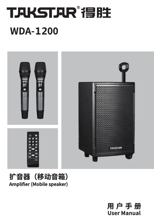
采用DSP方案,6.5英寸6.54.5约18KG仅适用于海拔2000米以下地区使用仅适用于非热带气候条件下使用17. 应将本产品放置在通风良好的位置,建议与周围物体留出10CM 以上的间隙。
通风孔不要覆 盖诸如报纸、桌布和窗帘等物品而妨碍通风;18.本产品应当连接到带保护接地连接的电网电源输出插座上;It can be used with two wireless microphones simultaneously in various occasions such as training, speech, outdoor promotions and dance parties. In order to better understand and use this product, please read the user manual carefully before use.If you have any questions or suggestions, please contact our local dealer.• Multifunctional active speaker system with audio output up to 120W.•UHF dual channels for reliable transmission and simultaneous use with two wirelessmicrophones.•Independent volume controls, EQ, Echo and 5 MIC modes, adaptable to various occasions.•Music playback function that supports playing audio files on flash drive and TF card.•Bluetooth music playback which links to Bluetooth devices like PC, phone and tablet.•DSP Vocal Removal function allows you to enjoy karaoke anywhere, anytime.•3.5mm & RCA Audio inputs/outputs for connection with external audio devices like TV,PC, CD and MP3 player.•Two 6.35mm connectors for wired microphone input.•Built-in 11.V/10,000 mAh rechargeable li-ion battery, suitable for indoor/outdoor use.Speaker Model: WDA-1200Amplifier Type: Class-DRated Power: 120WBass: 12’’, 38mm voice coil, 140mm magnet, 3ΩMid: 6.5’’, 25mm voice coil, 80mm magnet, 3ΩTreble: 25mm voice coil, 80mm magnet, 6ΩFrequency Response: 80Hz-15KHzBuilt-in Battery: 11.1V/10,000mAh rechargeable li-ion batteryOperation Time: 6.5hCharging Time: 4.5h THD: ≤ 0.5%UHF Range: 640MHz-690MHzWireless Mic Sensitivity: -80dBmWireless Mic Frequency Response: 100Hz-10KHz Wireless Mic Operating Range: 50m (open area) Wireless Mic Battery Life: 10hPower Requirement: 100~240V AC, 50/60Hz Operating Temperature: −10°C-45°CSpeaker Dimensions (L*W*H): 355*325*650mm Net Weight: approx. 18kgNote: The above data is measured by Takstar laboratory, and Takstar has the final interpretation right!Standard Configuration:WDA-1200 Speaker × 1 UHF Wireless Mic × 2Remote Control × 1AC Power Cord × 1AA Battery × 4UHF Antenna × 2AAA Battery × 2User Manual × 1Thank you for purchasing the TAKSTAR WDA-1200 Active Mobile Speaker, which features high fidelity sound, wide frequency response, stable performance, as well as low distortion and noise. Dear Customer,① LCD Display: display amplifier work mode and status.② SD Card Slot: by inserting an SD card, the speaker will auto play music stored in the card.③ USB Port: by inserting a USB flash drive, the speaker will auto play music stored in the drive.④ Music Pause/Play Button: press to play/pause.⑤ Switch Mode: press to switch mode: Bluetooth, Line IN or Media Play. Press and hold to enable/ disable vocal removal function.⑥ Loop: press to switch from Loop Single to Loop All.⑦ Previous Song: press to play the previous song.⑧ Next Song: press to play the next song.⑨ Recording Function: insert a USB/SD Card, then press Recording button to start recording your speech or singing into an audio file onto the USB/SD Card; press Recording button again to end the recording. By re-inserting the USB/SD Card, the speaker will play the recorded audio.⑩ Mic Mode: microphone mode controls (which are, Original, Pro, Popular, Indoor, and Outdoor).⑪ Wireless Mic-A Antenna Port: connect with an external antenna to boost signal strength.⑫ Wireless Mic-A Signal LED: lit when wireless mic-A is connected.⑬ Wireless Mic-A Volume Control Knob⑭ Wireless Mic-B Signal LED: lit when wireless mic-B is connected.⑮ Wireless Mic-B Volume Control Knob⑯ Wireless Mic-B Antenna Port: connect with an external antenna to boost signal strength.⑰ Low-Power Indicator: lit in red when battery is about to run out and requires charging as soon as possible.⑱ Charging Indicator: lit in red during charging, in green when fully charged.⑲ Power Switch: turn on/off speaker power.⑳ Audio Output: can be used to output the speaker audio towards other audio input devices, e.g., recorder, speaker, power amplifier.㉑ RCA Stereo Input: used to connect with an external audio source (DVD, PC, phone) via an RCA stereo cable for sound reinforcement.㉒ 3.5mm Headphone Jack: used to connect with an external audio source (DVD, PC, phone) via a3.5mm audio cable for sound reinforcement.㉓ Guitar Input: used to connect with a guitar via a 6.35mm cable for sound reinforcement.㉔ Mic Input: input for a wired microphone.㉕ Mic Master Volume Control Knob㉖ Mic Bass Volume Control Knob㉗ Mic Treble Volume Control Knob㉘ Mic Echo Control Knob: controls the duration of echo for microphone.㉙ Mic Delay Control Knob㉚ Mic Priority: auto lowers music volume when speaking through microphone and resumeswhen the speech ends.㉛ Music Bass Volume Control Knob㉜ Vocal Removal: one-key vocal removal which can turn a music into an accompaniment track for karaoke uses.㉝ Music Treble Volume Control Knob㉞ Music Master Volume Control Knob① Power Button② Number Buttons: for music folder selection③ MP3 Repeat Mode Selection④ Previous Song⑤ Volume Down⑥ Mode Selection⑦ Radio Channel –⑧ EQ Mode Controls (which are, Normal/Pop/Rock/Jazz/Classic/Country)⑨ Radio Channel +⑩ Next Song⑪Play/Pause⑫Volume UpNote: This remote control uses two AAA batteries.1.Power ON/OFFPower ON: install two 1.5V AA batteries, press the Power button to turn on the microphone, or press and hold the Power button to turn off. (DO NOT install the batteries in wrong direction)2.Switch FrequencyNoise during use, short transmission distance andpickup of other wireless microphone signals maybe the results of frequency interference, which can be avoided by switching frequency. Instructions: when powered on, press Frequency Switch button to select a desired frequency (16 channels in total). Receiver on the speaker will auto sync when frequency is switched. To select other channel, repeat the above steps. (If the interference issue remains, try the steps in below Instruction 3.)3.ID Lock / SyncFirst, turn off the speaker and the microphone. Press and hold the Sync button, then the Power button as well until the LCD screen flashes for 2s. Turn on the speaker power, after 3s, press the Sync button on the wireless mic to complete syncing. Sync/Lock is successfully when the Wireless Mic Indicator on the speaker is lit.One microphone can sync with multiple speakers, in other words, the speakers will receive signal from this microphone. To un-sync with a speaker, simply sync with another desired speaker at a different frequency. In case your microphone is broken and a new one is replaced by the manufacturer, follow these steps to sync.Capsule4.Microphone Factory ResetWhen the batteries are not installed, press and hold Sync button until you have installed the batteries. This will reset the device to factory defaults. (Pair with your speaker after reset)5.Battery StatusWhen the battery icon flashes on the LCD display, it’s time to prepare new batteries. When the icon turns from bright to dark and bright again, or the whole LCD is flashing, please change the batteries timely as that they are now dry and cannot properly power the microphone any more.6.Cautions1)Place the microphone out of reach of children.2)Take out the batteries when the microphone is not used.3)Do not randomly press setting buttons during normal use.4)Please replace the batteries when the microphone automatically turns off.To avoid electric shock, overheat, fire, radiation, explosion, mechanical risk and injury or property loss due to improper use, please read and observe the following items before use:1. Please check if the power of the connected equipment matches with that of this product beforeoperation. Adjust the volume to proper level during operation. Do not operate at over-power orhigh-volume level for extended time to avoid product malfunction or hearing impairment.2. If there is any abnormality during use (e.g., smoke, strange odor), please kill the power switchand unplug from power source, then send the product to the local dealer for repair.3. Never use battery with damaged insulation should a detachable battery is required; Do not chargea non-rechargeable battery.4. Dispose the waste battery in designated waste bin as per refuse classification; do not use aschildren toy or discard directly to avoid safety hazard or environmental damage.5. Keep this product and its accessories in a dry and ventilated area. Do not store in a humid or dusty area for extended time. Keep away from fire, rain, liquid intrusion, bumping, throwing, vibrating, or from blocking any ventilation openings, to prevent malfunction.6. The product must, when installed on walls or ceilings, be fixed firmly in place at adequate strength to prevent from falling.7. Please abide by safety rules during operation. Do not use the product in places prohibited by laws or regulations to avoid accident.8. Do not disassemble or repair the product by yourself to avoid injury. If you have any questions orrequire any services, please contact our local dealer.9. Put this product at least 60cm away from PC or TV due to its strong magnet inside.10. The product has a built-in rechargeable lithium-ion battery. Please recharge once every threemonths if not used for extended periods. Recommended to recharge timely after each use.11. Only use lithium-ion battery of the same specifications as the original for replacement. Dispose any obsolete battery properly.12. Keep away from high temperature.13. Place in a ventilated area.14. Keep away from humid areas.15. Turn off the product power before unplugging the power cord.16. Unplug from power source when not used for extended periods.17. Place in a well-ventilated area, recommended to be at least 10cm away from surrounding objects. Do not block ventilation openings with objects such as newspaper, table cloth and curtain.18. The product should be connected to a mains outlet with grounding protection.Suitable only for altitudes below 2,000mSuitable only fornon-tropical climates 10。
打包机说明书
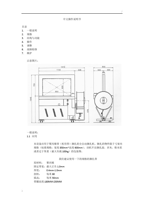
中文操作说明书目录1.一般说明2.规格3.结构与功能4.操作5.调整6.故障检修7.维护示意图片:一般说明:1.1应用本设备应用于聚丙烯带(机用带)捆扎的全自动捆扎机。
捆扎的物件限于弓架内规格(标准规格:宽度850mm*高度600mm)。
该机不宜捆扎湿,多灰,粉末状或者过于笨重(最大负载100kg)的包装物。
我们建议使用一下的规格的捆扎带原材料:聚丙烯固定带宽:最大正负1.0mm厚度:0.4mm-1.0mm扭转:每米60弧高:每米50mm带圈高度:180MM-230MM带圈纸芯内径:200mm-405mm1.2安装设备必须安装在靠近电源机及干燥平坦的硬质地板上,并可靠固定不移动。
电源必须与机器侧面的铭牌说明相一致。
安装地点应符合以下条件:室温:-20℃-=+50℃、地板:最大负载350公斤/平方米空间:最小2米*1.5米严重警告:如果不按照机器说明书要求正确安装,将导致严重后果。
严重警告:电源连接线插头必须牢固,电源插座必须有接地保护。
1.3运输和储存长途运输或者长期保管机器,必须用木箱或者硬纸板箱包装,固定在结实的垫板上。
并在包装箱内放吸潮剂,在机器内部喷涂防锈剂。
切勿在包装箱顶部对放任何重物,运输和储存时不要将机器倒置。
长途运输或长期保存机器后,建议在机器接上电源前,先手动检查所有活动部件,以避免电气设备过负荷。
随机供应的标准附件:1.工具:1套2.弓架活页弹簧:5件3.紧力臂夹刀弹簧:1件4.紧力臂弹簧1件5.紧力臂制动器弹簧1件6.所有其他品种的弹簧1套7.电热头1件8.说明书1份2-1. 技术要求:批准CE2-2. 规格:尺寸:宽1412mm 长600mm 高1540mm净重:220kgs毛重:230kgs带宽:8, 9,10, 12, 12.7, 15.5,18,19mm带盘:PP带纸芯内径200mm-280mm(可调)捆扎速度: 26次每分钟捆扎范围:最小。
宽100mm 高30mm(最大为弓架内规格)粘合方法:热熔法捆扎紧度:5kg-80kg功率:0.85KVA电源:3PH,220V-380V (50 HZ /60HZ)1PH,110V-220V (50 HZ /60HZ)可调选项:弓架规格,带宽,电源,进带传感器说明:**标准弓架宽850mm 高600mm**如有改变,恕不另行通知结构与功能:外观图:4-1:操作前的注意事项:检查电源与机器侧面铭牌说明是否一致。
DC-1500~1200焊机操作手册
第 2 页 共 42 页
子上,连接工件电缆到另一端子上。
使主焊机上的“焊丝正极—焊丝负极”两位开关的设置与焊丝电缆的连接极性相一致。该开
关的设置对林肯送丝操作相对主焊机的正常控制是非常必要的。
启动焊机
按下“启动”(START)和“停止”(STOP)按钮时,进行启动或停止焊机工作。当焊机进
行工作时,位于控制面板中间的红色指示灯发亮。
c. 对冷起动而言,使用的一种工件是干净的和焊丝与电极板相连;
d. 对热起动而言,当电线连接到工作状态以前,移动应该开始;
e. 设置 NA-3 开路电压大概范围,对最初的试验状态,选择的电压设置在下面表的最低的状
态,逐渐地设置控制到 2。
这是一个大概的设置,应该注意到使用 DC-1500,OCV 要求一个理想的起动比别的理想电
对本设备上进行工作前,在保险盒或开关处关闭输入电源。
请勿接触设备带电部位。
注:查找“触发板”和“控制/故障保护电路板”的 P.C.板时,打开焊机左侧上部机箱面板,印刷
第 3 页 共 42 页
电路板上有名牌标注。 1.正常的维护 a. 风扇的马达是封闭的。 b. 在极其灰尘多的情况下,灰尘附着在空气流通道内,将使焊机发热,定期地用低压风吹掉灰
制回路还通过焊机面板上的 8A 保险向 NA—5 控制箱提供 AC115V,1000VA 控制电源。
触发电路板 G—1587—1 接受控制板送来的移相控制电压,按照移相要求发出六路触发脉冲
去触发主回路可控硅,通过改变可控硅的导通角来改变焊机输出的大小。
控制板 G—1530 是 DC—1500 最复杂的部件,他的功能是控制和保护,按功能划分,大致可
变压器线圈及整流器具有抵抗潮湿、易腐蚀环境的功能。
NOBLES Speedshine 1200 1600 2000 120V 操作员和零件手册说明书

QTY. 1 1 1 1 1 1 3 4 2 1 1 1 2 6 5 1 1 1 2 1 1 2 1 1 1
Home Speedshinet 1200/1600/2000 (09–02) Find... Go To..
23
PARTS LIST LISTA DE PIEZAS
2 1
4 36 36 3
REF 23 24 25 26 27 28 29 30 31 32 33 34 35 36 37 38 39 40 41 42 43 44 45 46 47
PART # 6010.16 600987 100355 140259 602849 610974 230852 140147 140146 140604 230860 200821 602750 140052 140864 230859 140402 140881 140524 130204 130141 140437 140864 230773 130176
BASE GROUP GRUPO BASE
7 8
9 5 6
22
23 24
10 11
12
13
14
15 16 17
18
25
21 17
16 26 27
28
44 45 36
26
29
27
43
19 20
19
42 28
41 40
30 31
32
37
26
33
27
43
39
38 35 34
24
Home Find... Go To..
DESCRIPTION SCREW, 8–32X1 SPRING SLEEVE, LOCKING SCREW, 1/4–20X5/8 GRIP, CORD DCORD, 14/3X75’ YELLOW PLATE, BACKING SLEEVE, .44ODX.25BX.21L BUSHING, .50ODX.25BX.21L PIN, GROOVE 1/4X3/4 HANDLE, LATCH GRIP, LATCH HOOK, CORD WASHER, 1/4 EXT SCREW, 1/4–20X3/4 CHANNEL, LATCH HANDLE SPRING, HANDLE LATCH SCREW, 1/4–20X1 NUT, 1/4–20 KEP CORD, 14/3X57” BLACK BUSHING, STRAIN–RELIEF SPRING SCREW, 1/4–20X3/4 BRACKET, SPRING DBELT CLIP, STRAIN–RELIEF (OPTIONAL)
电脑包缝机面板操作说明书

电脑包缝机面板操作说明书2017-05-8Instructions of overlock sewing machine panel operation8th May.2017目录contents1.显示及操作界面Display and operation menu (2)1.1显示界面介绍Operation Panel Instructions (2)1.2按键设置介绍button setting Instructions (3)2.常用参数设置common parameters setting (3)2.1全智能/半智能/全电脑模式的设置 (3)Automatic/Semi‐automatic/Full manual mode settings (3)2.2抬压脚模式的设置Presser foot lifter mode setting (5)2.3剪线参数的设置Trimmer parameter setting (5)2.4转速的修改Modify speed (6)2.5技术区参数的修改Change technician parameter (6)2.6恢复出厂设置Restore factory setting (7)2.7语音种类设置Voice language setting (7)2.8穿线灯开关的设置LED light setting (7)2.9按键锁定设置Button lock setting (8)3参数列表parameters list (9)3.1操作参数说明表Parameter description (9)4调速器Speed controller (15)1.显示及操作界面Display and operation menu1.1显示界面介绍Operation Panel Instructions序号No.图标Icon 说明Description备注Remark1用户参数设置键Customer parameter settings 2左移键Left button1、语音种类设置键Voice language setting2、参数内容区内,向左选择参数项Towards the left to choose parameter 3上移键Up button1、向上调速键Increase speed button2、参数内容区内,设定数值递增键Increase the number within a parameter 4下移键Down button1、向下调速键Decrease speed button2、参数内容区内,设定数值递减键Decrease the number within a parameter 5右移键Right button1、机头灯亮度调节control machine head LCD light brightness 2、参数内容区内,向右选择参数项Towards the right to choose parameter within a parameter6缝纫模式键Sewing mode button 更改缝纫模式Change the sewing mode7抬压脚功能键Presser foot lifter function button更改自动抬压脚模式Change auto presser foot lifter mode8剪线参数设置键Trimmer parameter setting 更改剪线线头长短及剪线开关Change the length of the thread and thread switch 9复位键Reset button 长按1.5S 恢复出厂设置long press for 1.5seconds restoring factory setting 10语音导航键Voice navigation button语音播报开关voice broadcast switch1.2按键设置介绍button setting Instructions长按P键()约1.5秒,将进入用户参数调整模式;通过左移键()和右移键()修改参数项,按上移键()和下移键()修改相应参数的值,按P键()确认并保存,按左移键()或右移键()不保存并退到参数项设置界面,再次按P键()退到待机界面。
贴片机说明书TP-1200D

贴片机说明书KY-TP1200D单位名称:科亿电子设备公司地址:市番禺区大石街河村山庄路18号之二3楼电话:1 1传真:1Http://.keyi020.目录前言....................................................................................第一页产品介绍与用途…………………........................................第二页注意事项…………………………..………………….....…….第三页机器的操作...………………………………………........……..第四页机器的保养……………………………………………………常见的故障处理………………………………………………前言感您使用KY-TP1200D贴片机。
您能成为我们的用户,是我们莫大的荣幸。
为了使您能尽快熟练地操作贴片机,请您详细阅读本使用说明书。
在编写本使用说明书时我们非常小心和严谨,并认为使用说明书所提供的信息是正确可靠的,然而难免会有错误和疏漏之处,请您多加包涵并热忱欢迎您的指正。
如果您在使用过程中发现什么问题,请及时与我们联系。
您的使用。
第1页产品介绍科亿单头贴片机是一款主要针对于LED照明行业的贴片机,它的主要结构由机械与电气组成,机械结构由三个轴组成分别是,X轴(左右方向键控制,矩形阵列中的行,也称PCB 平台);Y轴(上下方向键控制,矩形阵列中的列);Z轴(pgup与pgdown键控制,也称吸嘴上下轴)。
电气由:家庭用电220V和通用电压0.6~0.8Mpa气压。
主要用来小规模LED贴片加工。
建议红色部分将电气的组成写的详细一点,比如用什么电机、品牌等,气动方面采用了什么真空发生器、电磁阀。
简要说明优点。
第2页注意事项第一:在装机完成后一定要检查是否有连接地线,以防触电。
第二:检查是否有气供应,气压保持在0.6~0.8Mpa以。
YUDO Sensw-800(S),1200(S),1700(S) 说明书
柳道机械有限公司 YUDO-SUNS CO., LTD. 使用说明书前言此次承蒙购买本公司的横走行自动取出机<Sensw-series>特此致谢。
本机械是通过与成形机的连动,从模具中自动取出成型品,通过传送带,搬送到指定场所为目的而设计生产的。
本说明书记载了本机的性能,以及安全注意事项。
为了充分理解本机的性能及灵活地使用本机,请从头至尾详细阅读本说明书。
阅读后,请将本说明书放置于机械的附近,以便于阅读和保管。
※本说明书为标准型,关于选项功能和特殊机能,请参照其他的使用说明书。
※关于本说明书中的专业用语的说明主流道 (流道):SPRUE分流道(水口):RUNNER闸门:GATE·Sensw-800(s)·Sensw-1200(s)·Sensw-1700(s)目录1. 安全注意事项 (1)1-1.使用说明书的构成 (1)1-2.关于本书记录的注意事项 (1)1-3.注意事项 (1)1-4.关于警告标志 (5)1-5.机械规格 (6)2.各部件名称和运行 (9)2-1.构成图 (9)2-2.基本动作图 (9)2-3.制品侧上下单元 (10)2-4.水口侧上下单元(S型) (12)2-5.前后单元 (14)2-6.行进轨道单元 (15)2-7.电磁阀单元 (16)2-8.限位开关的配置 (18)3.保养检查 (20)■定期检查周期表 (20)■给油指导图 (22)■给油的方法 (23)■润滑油 (24)4.零部件清单 (25)5.消耗品清单 (25)6.各轴驱动部分零部件表 (28)7.空气回路图 (32)8.整体机械图 (37)Ⅰ.模块真空发生单元Ⅱ.PS-30-i-1. 安全注意事项1-1.使用说明书的构成本说明书是为了安全正确地使用取出机本体(机械侧),记载了有关机械的功能、设定方法、维修以及操作上的安全注意事项等。
本机械说明书的构成,除取出机本体的使用说明书之外,还包括控制箱的《操作篇》、《技术篇》等。
Dorner Mfg. Corp. 电动机控制配件安装及零部件手册 Rev. A说明书

For other service manuals visit our website at:/service_manuals.aspDORNER MFG. CORP .INSIDE THE USA OUTSIDE THE USA P .O. Box 20 • 975 Cottonwood Ave.TEL: 1-800-397-8664TEL: 262-367-7600Hartland, WI 53029-0020 USAFAX: 1-800-369-2440FAX: 262-367-5827851-825 Rev. AMotor Control AccessoriesInstallation and Parts ManualEmergency Stop KitJog Button Kit Control Stop KitPhoto Eye Kit Photo Eye Bracket KitTable of ContentsTable of Contents (2)Introduction (3)Warnings − General Safety (4)Accessories Specifications (5)Product Description (6)Emergency Stop Kit (6)Control Stop Kit (6)Jog Push Button Kit (6)Photo Eye Kit (6)Photo Eye Bracket Kit (7)Linking Cable Kit (7)Accessories Installation (8)Required Tools (8)Button Box Kits - Vertical Mounting to Conveyor (8)Button Box Kits - Horizontal Mounting to Conveyor (8)Button Box Kits - Stand Mount (9)Photo Eye and Bracket Kits - Mounting to Conveyor (9)Linking Cable Kit (9)Wiring and Operation (10)Wiring (10)Operation (10)Service Parts (11)Emergency Stop Kit (11)Control Stop Kit (12)Jog Push Button Kit (13)Photo Eye Kit (14)Photo Eye Bracket Kit - Through Beam (15)Linking Kit (16)Notes (17)Return Policy (18)Motor Control AccessoriesDorner Mfg. Corp.2851-825 Rev. AMotor Control Accessories IntroductionUpon receipt of shipment:•Compare shipment with packing slip. Contact factory regarding discrepancies.•Inspect packages for shipping damage. Contact carrier regarding damage.•Accessories may be shipped loose. See accessory instruc-tions for installation.The Dorner Limited Warranty applies.Dorner reserves the right to make changes at any time without notice or obligation.Dorner has convenient, pre-configured kits of Key Service Parts for all conveyor products. These time saving kits are easy to order, designed for fast installation, and guarantee you will have what you need when you need it. Key Parts and Kits are marked in the Service Parts section of thismanual with the Performance Parts Kits logo .A CAUTIONSome illustrations may show guardsremoved. DO NOT operate equipment withoutguards.851-825 Rev. A3Dorner Mfg. Corp.Dorner Mfg. Corp.4851-825 Rev. AMotor Control AccessoriesWarnings − General SafetyA WARNINGThe safety alert symbol, black triangle with white exclamation, is used to alert you to potential personal injury hazards.SEVERE HAZARD!KEEP OFF CONVEYORS. Climbing, sitting,walking or riding on conveyor will cause severe injury.EXPLOSION HAZARD!•DO NOT OPERATE CONVEYORS IN AN EXPLOSIVE ENVIRONMENT. The electric gearmotor generates heat and could ignite combustible vapors.•Failure to comply will result in death or serious injury.A WARNINGController must be properly grounded. Failure to properly ground controller may cause injury to personnel.SEVERE HAZARD!Hazardous voltage will cause severe injury or death. LOCKOUT POWER BEFOREWIRING.A WARNINGSEVERE HAZARD!Exposed moving parts can cause severe injury. DO NOT ATTEMPT ADJUSTMENTS WITH CONVEYOR RUNNING. LOCK OUT POWER before removing guards or performing maintenance.A WARNINGSEVERE HAZARD!•Dorner cannot control the physicalinstallation and application of conveyors. Taking protective measures is the responsibility of the user.•When conveyors are used in conjunction with other equipment or as part of a multiple conveyor system, CHECK FOR POTENTIAL PINCH POINTS and other mechanical hazards before system start-up.•Failure to comply could result in serious injury.Accessories SpecificationsModel Number Description75M-ES-1Emergency Stop Kit75M-CS-1Control Stop Kit75M-JG-1Jog Push Button Kit75M-PE-1Photo Eye Kit with 2" Height Adjustment75M-PE-2Photo Eye Kit with 5" Height Adjustment75M-PM-1Reflective Photo Eye Bracket Kit with 2" Height Adjustment75M-PM-2Reflective Photo Eye Bracket Kit with 5" Height Adjustment75M-PM-3Through Beam Photo Eye Bracket Kit with 2" Height Adjustment75M-PM-4Through Beam Photo Eye Bracket Kit with 5" Height Adjustment75M-PM-5Convergence Photo Eye Bracket Kit with 2" Height Adjustment75M-PM-6Convergence Photo Eye Bracket Kit with 5" Height Adjustment75M-LC-1Linking Cable Kit 6 ft. (1.83 m) long75M-LC-2Linking Cable Kit 15 ft. (4.57 m) longMotor Control Accessories851-825 Rev. A5Dorner Mfg. Corp.Dorner Mfg. Corp.6851-825 Rev. AMotor Control AccessoriesProduct DescriptionEmergency Stop KitRefer to (Figure 1) for typical components.Figure 1Control Stop KitRefer to (Figure 2) for typical components.Figure 2Jog Push Button KitRefer to (Figure 3) for typical components.Figure 3Photo Eye KitRefer to (Figure 4) for typical components.Figure 4Typical Components1Emergency Stop Box 2Drop in T -Bars (x2) 3.50” Spacers (x2)4M6-1.00 x 20mm Low Head Cap Screws (x2)5M6-1.00 x 12mm Low Head Cap Screws (x2)Typical Components1Control Stop Box 2Drop in T -Bars (x2) 3.50” Spacers (x2)4M6-1.00 x 20mm Low Head Cap Screws (x2) 5M6-1.00 x 12mm Low Head Cap Screws (x2)Typical Components1Jog Push Button Box 2Drop in T-Bars (x2) 3.50” Spacers (x2)4M6-1.00 x 20mm Low Head Cap Screws (x2) 5M6-1.00 x 12mm Low Head Cap Screws (x2)Typical Components1Photo Eye Assembly 2Reflector Assembly3M6-1.00 x 12mm Low Head Cap Screws (x4) 4Drop in T -Bars (x2)851-825 Rev. A7Dorner Mfg. Corp.Motor Control AccessoriesProduct DescriptionPhoto Eye Bracket KitRefer to (Figure 5) for typical components.Figure 5Linking Cable KitRefer to (Figure 6) for typical components.Figure 6Typical Components1Photo Eye Bracket Assembly 2Reflector Assembly3M6-1.00 x 12mm Low Head Cap Screws (x4) 4Drop in T -Bars (x2)Typical Components1Cable - 4P Micro Connect 2Wire Ties (x3) 3Drop in T -Bars (x2)4M6-1.00 x 20mm Low Head Cap Screws (x3) 5Mounting Cable Ties (x3) 6T -Slot Strip Closures (x3) 7Hex KeyDorner Mfg. Corp.8851-825 Rev. AMotor Control AccessoriesAccessories InstallationRequired Tools• 6 mm hex head wrenchButton Box Kits - Vertical Mounting to Conveyor1.Install t-bars (Figure 7,item 1) into conveyor t-slot.Figure 72.Attach button box kit (Figure 8,item 1) to conveyor with screws (Figure 8,item 2).Figure 83.Slide button box kit to its desired mounting location along conveyor and tighten both screws.Button Box Kits - Horizontal Mounting to Conveyor1.Install t-bars (Figure 9,item 1) into conveyor t-slot.Figure 92.Attach button box kit (Figure 10,item 1) to conveyor with spacers (Figure 10,item 2) and screws (Figure 10,item 3).Figure103.Slide button box kit to its desired mounting location along conveyor and tighten both screws.851-825 Rev. A9Dorner Mfg. Corp.Motor Control AccessoriesAccessories InstallationButton Box Kits - Stand Mount1.Install t-bar into t-slot.2.Partially thread controller lower mounting bar (Figure 11,item 1) to t-bar with screw (Figure 11,item 2).Figure 113.Install second t-bar into stand t-slot4.Partially thread controller top mounting bar to t-bar with screw.5.Slide controller to its desired mounting location and tighten both screws.Photo Eye and Bracket Kits - Mounting to Conveyor1.Install t-bars (Figure 12,item 1) into conveyor t-slot.Figure 122.Attach photo eye assembly (Figure 13,item 1) to conveyor with screws (Figure 13,item 2).Figure 133.Slide photo eye to its desired mounting location alongconveyor and tighten both screws.4.Repeat steps 1-3 for the reflector assembly on opposite side on the conveyor.Linking Cable Kit1.To contain a long run of wiring cable in the conveyor t-slot, use several short lengths of t-slot strip closures (Figure 14,item 1).Figure 142.To route cable over a previously mounted component or to anchor the cable, use the mounting cable ties (Figure 15,item 1) and single drop-in t-bars (Figure15,item 2). Secure with screws (Figure 15,item 3).Figure 15Wiring and OperationWiring1.Plug in accessory to M12 port.2.Verify P100 is set to 1.a.Press M.b.Scroll to P100 and press M.c.Set value to 1 and press M.Operation1.Power VFD.2.If fault message appears, trigger accessory.3.Run conveyor using designed accessory application.NOTEKey pad Green "Run" button will display"ERR" when pressed with P100 = 1. The Red"Stop" button will always work. To reset afterRed "Stop" button is pressed, trigger theaccessory.Motor Control AccessoriesDorner Mfg. Corp.10851-825 Rev. A851-825 Rev. A 11Dorner Mfg. Corp.Motor Control AccessoriesService PartsEmergency Stop Kit NOTE For replacement parts other than those shown in this section, contact an authorized Dorner Service Centeror the factory. Key Service Parts and Kits are identified by the Performance Parts Kits logo . Dornerrecommends keeping these parts on hand.Item Part NumberDescription 1201103Mounting Bracket 2805-053Receptacle Cord 3805-057Wire Nut 4805-1005Cord Grip 5805-655Surface Mounted Relay 6805-805Power Cord 7817-243Push Button Box 8830-210Button Latch 9830-212Contact Block Switch 10830-216Red Push Button 11830-217Push Button Nameplate 12639971M Single Drop-In T -bar 13807-1572Spacer 14950612M Low Head Cap Screw M6-1.00 x 12mm 15950620M Low Head Cap Screw M6-1.00 x 20mmDorner Mfg. Corp.12851-825 Rev. A Motor Control AccessoriesService PartsControl Stop Kit Item Part NumberDescription 1201103Mounting Bracket 2201105Legend Plate 3809-314Male Micro Connector 4812-067O-Ring 5807-239Push Button Box 6830-210Button Latch 7830-212Contact Block Switch-Normally Closed 8830-214Control Stop Button 9639971MSingle Drop-In T -bar 10807-1572Spacer 11950612MLow Head Cap Screw M6-1.00 x 12mm 12950620M Low Head Cap Screw M6-1.00 x 20mm851-825 Rev. A 13Dorner Mfg. Corp.Motor Control AccessoriesService PartsJog Push Button Kit Item Part NumberDescription 1201103Mounting Bracket 2677785PLegend Plate 3809-314Male Micro Connector 4812-067O-Ring 5807-239Push Button Box 6830-210Button Latch 7830-211Contact Block Switch-Normally Open 8830-213Push Button 9639971MSingle Drop-In T -bar 10807-1572Spacer 11950612MLow Head Cap Screw M6-1.00 x 12mm 12950620M Low Head Cap Screw M6-1.00 x 20mmDorner Mfg. Corp.14851-825 Rev. A Motor Control AccessoriesService PartsPhoto Eye Kit Item Part NumberDescription 1200830MDrop-In T -bar 22011042" Mounting Sensor Shaft 202027M5" Mounting Sensor Shaft 3807-1390Reflector Mount Clamp 4807-1391Photo Eye Mount Clamp 5809-289Reflector Sensor 6809-315Photo Eye Sensor 7202004Mounting Bracket 8807-948Shaft Cap 9950612MLow Head Cap Screw M6-1.00 x 12mm 10950616M Low Head Cap Screw M6-1.00 x 16mm851-825 Rev. A 15Dorner Mfg. Corp.Motor Control AccessoriesService PartsPhoto Eye Bracket Kit - Through Beam Item Part NumberDescription 1200830M Drop-In T -bar 22011042" Mounting Sensor Shaft 202027M 5" Mounting Sensor Shaft 3202004Mounting Bracket 4807-1391Photo Eye Mount Clamp 5807-948Shaft Cap 6950612M Low Head Cap Screw M6-1.00 x 12mm 7950616M Low Head Cap Screw M6-1.00 x 16mmDorner Mfg. Corp.16851-825 Rev. A Motor Control AccessoriesService PartsLinking Kit Item Part NumberDescription 1639971M Single Drop-In T -bar 2675232T -Slot Strip Closure 3805-063Wire Tie 4805-608Mounting Cable Tie 5807-565Hex Key 6809-312 2 ft. Meter Cable 809-313 5 ft. Meter Cable 7950612M Low Head Cap Screw M6-1.00 x 12mmNotesMotor Control Accessories851-825 Rev. A17Dorner Mfg. Corp.851-825 Rev. A Printed in U.S.A.Dorner Mfg. Corp. reserves the right to change or discontinue products without notice. Allproducts and services are covered in accordance with our standard warranty. All rights reserved. © Dorner Mfg. Corp. 2014DORNER MFG. CORP .975 Cottonwood Ave., PO Box 20 Hartland, WI 53029-0020 USA TEL 1-800-397-8664 (USA)FAX 1-800-369-2440 (USA)Internet: Outside the USA:TEL 1-262-367-7600FAX 1-262-367-5827Return PolicyReturns must have prior written factory authorization or they will not be accepted. Items that are returned to Dorner without authorization will not be credited nor returned to the original sender. When calling for authorization, please have the following information ready for the Dorner factory representative or your local distributor:1.Name and address of customer.2.Dorner part number(s) of item(s) being returned.3.Reason for return.4.Customer's original order number used when ordering the item(s).5.Dorner or distributor invoice number (if available, part serial number).A representative will discuss action to be taken on the returned items and provide a Returned Goods Authorization (RMA) number for reference. RMA will automatically close 30 days after being issued. To get credit, items must be new and undamaged. There will be a return charge on all items returned for credit, where Dorner was not at fault. It is the customer’s responsibility to prevent damage during return shipping. Damaged or modified items will not be accepted. The customer is responsible for return freight.Returns will not be accep ted after 60 days from original invoice date. The return charge covers inspection, cleaning,disassembly, disposal and reissuing of components to inventory. If a replacement is needed prior to evaluation of returned item, a purchase order must be issued. Credit (if any) is issued only after return and evaluation is complete.Dorner has representatives throughout the world. Contact Dorner for the name of your local representative. Our Customer Service Team will gladly help with your questions on Dorner products.For a copy of Dorner's Warranty, contact factory, distributor, service center or visit our website at .For replacement parts, contact an authorized Dorner Service Center or the factory.Product TypeStandard Products Engineered to order parts Product Line Conveyors Gearmotors & Mounting Packages Support Stands Accessories Spare Parts (non-belt)Spare Belts - Standard Flat Fabric Spare Belts - Cleated & Specialty FabricSpare Belts - Plastic Chain All equipment and parts 110030% return fee for all products except:50% return fee for conveyors with modular belt,cleated belt or specialty belts non-returnable case-by-case22002200 Modular Belt2200 Precision Move23002300 Modular Belt32003200 LPZ3200 Precision Move4100520053006200Controls7200 / 730050% return fee for all products 7350non-returnable 736074007600。
Sure-Feed SE-1200-P W球架操作和零件手册
Sure-Feed Engineering Inc. SE-1200-P W/ BALL RACKOperation & Parts ManualSure-FeedEngineering IncSE 1200 PC & PS Series OWNERS MANUALTable of Contents1. Set-up instructions2. Bridge-Tramming Procedure3. Operation instructions4. Cleaning5. Troubleshooting6. Parts manual7. Electrical schematic8. Warranty informationSure-Feed Engineering Inc.Set-up Instructions1. Plug the feeder power cord into a 110 VAC grounded outlet.2. With the feeder ON/OFF switch in the off position, loosen the two side guidesand move them all the way to the sides of the feeder. Then loosen the rear guide ramp and move it all the way back out of the way.3. Place a single piece of the material to be fed on the feeder centering thematerial relative to the separating device.4. Move each side guide in to meet the material and then back them off about1/16”.5. Tighten the bottom thumbscrews on each side guide.6. If adjustment is required, turn the separator knob clockwise until you caneasily pass the single piece of material under the separator. While moving the material back and forth under the separator, turn the separator knobcounter-clockwise until you feel resistance from the separator. At this point, you have roughed in the separator setting and will need to tune it in after the completion of the following set-up steps. If the resistance under one separator wheel is not the same as under the separator wheel, the bridge needs to be trammed. See bridge-tramming procedure before proceeding.7. Place a handful of material in the feeder allowing the material to shingleforward into the separator.8. Move the back guide forward so as to use the back guide wedge shape tosupport the back edge of the material stack. At this point, you have roughed in the back guide setting and will need to tune it in later.9. Add enough material to the stack to fill about half the height of the sideguides.10. Move the top of each side guide out slightly so as to create a funnel effectand then tighten the top adjusting handles on each side guide.Sure-Feed Engineering Inc.Set-up Instructions Cont.11. You are now ready to feed some material. With the power still off, turn thespeed control counter-clockwise to the minimum position.12. Turn the power switch on and cycle the feeder by holding the red stop buttondown and pressing green start button Observe the consistency in which the material is feeding.13. By turning the separator knob slightly in either direction, you will change theway the material is separating.14. By moving the back guide in and out, you will quickly find the position thatcreates the most consistent separation and gap. There must be a gapbetween pieces when they pass the opposing photo eyes at the discharge of the feeder. If there is no gap, the feeder will not count pieces correctly.15. One important item to note; There is no substitution for experience. Byworking with the feeder, you will notice that the combination of separatorsetting and the back guide adjustment together will have the greatest effect on separation. Generally, the longer the piece of material, the flatter thematerial stack should be. Conversely, the shorter the piece of material, the closer the back guide adjustment should be to the material, adding wedge to the material stack. You will also notice that by moving the back guide forward (increasing the wedge), you can open the separator and still achieve good separation.Sure-Feed Engineering Inc.Bridge-Tramming ProcedureNormally this is a factory setting that does not require adjustment. However, raising the bridge may be required to run thick material and this adjustment may be required. This setting is critical to the performance of the feeder. This will ensure that the separator wheels are level with respect to the nip rollers. To do this, first loosen the bridge mounting screws (Item 11, Fig. 6-3) on both sides of the bridge. Turn the separator adjustment CCW until the separator wheels are in their lowest position. Now place a thin strip of paper under each separator wheel (it is best to cut one piece of paper into two strips to ensure that the strips are the same thickness). Tighten one screw on each side. Move the paper strips to feel if the resistance is equal under each separator wheel. If one moves with less resistance than the other, loosen the screw on the side that is tighter and raise that side of the bridge slightly and tighten screw. Check the resistance under each separator wheel with the paper strips again and adjust accordingly. This procedure must be followed whenever the bridge is adjusted up or down for materials with different thickness. This adjustment is “very” critical when feeding thin materials.Sure-Feed Engineering Inc.Operation InstructionsBATCH COUNTING•Your Sure-Feed Engineering feeder is equipped with a batch counter. The batch value is pre-set from the factory with a value of 1. To change the batch value, first locate the batch controller on the rear of the feeder. Press thebutton labeled (P2) once to activate the setting mode. Now by pressing any of the buttons you can change the corresponding digit in the desired batchvalue. By pressing the P1 button you can change the 0 to 9 values. Bypressing the P2 button you can change the 10 to 90 values. P3 changes the 100 to 900 values and so forth. As you change each digit of the value, you will see the LED display change accordingly. When you have displayed thedesired batch value press the ENTER button (E) followed by the reset button (R). You are now ready to batch the desired number of pieces. (Note: You must press ENTER followed by RESET or changes will not be saved.) The new value will be stored until a different value is properly set even when the power is turned off to the feeder.•Another feature associated with your batch counter is a deceleration phase at the end of the batch. . Press the button labeled (P1) once to activate thesetting mode. Now by pressing the (P1) button again you can adjust thenumber of pieces that the feeder decelerates for. For example, if the setting is(1) the feeder slows down during the last piece in the batch. The value of 1 isnormally the best setting, however if the feeder is running slow a value of (0) may work better. However, if the feeder is running fast, a deceleration value of (0) may not stop the feeder quick enough. You can extend the life of the feeder by maintaining a deceleration (P1) value of (1) or (2).Sure-Feed Engineering Inc.Operation InstructionsMANUAL OPERATION•There are (2) recessed buttons on the back of the feeder. The red button is the Stop / Reset button. The green button will start the feeder manually. Press the green button and the feeder will feed a batch pre-determined by the batch counter. Hold the red button down and press the green button and the feeder will feed a single piece.ERRORS•There is a red LED near the manual push buttons. The feeder will stop and This LED will light up or flash if an error has occurred. The LED will flash for a missing piece, out of paper, and excessive batch time. The LED will remain lit for a paper jam.Sure-Feed Engineering Inc.Cleaning InstructionsClean rollers and belts are very important to the performance of the feeder. Use a clean rag dampened with Isopropyl Rubbing alcohol, 70% by volume (typically available in drug stores) to clean belts and rollers. Do not use any other solvents, cleaners, or abrasive cleaners on the rollers or belts as they may damage the rubber.Warning: Isopropyl rubbing alcohol is very flammable! Always unplug the machine before cleaning belts and rollers. DO NOT! use near an open flame, sparks, or any other source of ignition. DO NOT! Smoke in the vicinity of the alcohol fumes. Allow used rags to air-dry before throwing them in the trash. Dispose of used rags properly.Other areas of the machine should be wiped clean with a clean dry rag.Sure-Feed Engineering Inc.Troubleshooting GuideProblem Solution Feeder will not run. Check circuit breaker condition.Check outlet power source.Check power switch.Feeder runs but no material is being dispensed. Check material supply.Remove all material and follow setup procedure.Check rollers and belts for excessive wear or dirt.Feeder does not create a gap between pieces. Lower separator adjustment and observe. If a gap is not present after this adjustment, return separator to original position and move the back guide forward.Feeder does not detect material. Adjust position of the sensor.Thick material does not feed well. Decrease the height at the back of thematerial stack.Increase the opening at the separationdevice (the thicker the material the lesscritical the setting is).Sure-Feed Engineering Inc.Troubleshooting Guide Cont.Problem SolutionThin material does not feed. Adjust separation device as described insection 2.Remove material and fan the stackallowing air to separate the pieces.Raise the rear of the material stack bymoving the wedge forward.Material feeds double. After confirming set up is correct,inspect the o-rings. If the o-rings areworn past the shoulder of the separatorwheel, they will not be effective. Replacethe o-rings and reset the gap.Sure-Feed Engineering Inc.Parts ManualFEEDER ASSEMBLY (FIG. 6-1)NO. QTY. DESCRIPTIONITEM PART1 99000-001 1 BELT, TIMING 90XL2 99000-041 1 BELT, TIMING 100XL3 99000-003 1 BELT, TIMING 120XL4 99000-004 3 BELT, RED GUMELEVATORBELT,5 99000-005 26 SEE FIG. 6-2 1 SEPERATOR DEVICE ASSEMBLY7 SEE FIG. 6-3 1 SIDE GUIDE ASSEMBLY8 SEE FIG. 6-4 1 FRONT SHAFT ASSEMBLY9 SEE FIG. 6-4 1 NIP ROLLER SHAFT ASSEMBLY10 SEE FIG. 6-4 1 SUPPORT IDLER SHAFT ASSEMBLY11 SEE FIG. 6-4 1 MAIN SHAFT ASSEMBLY12 SEE FIG. 6-5 1 CLUTCH SHAFT ASSEMBLY13 SEE FIG. 6-6 1 ELEVATOR SHAFT ASSEMBLY14 SEE FIG. 6-7 1 PAPER SLIDE ASSEMBLY15 SEE FIG. 6-5 1 MOTOR ASSEMBLY16 SEE FIG. 6-8 1 CHASSIS ASSEMBLY17 SEE FIG. 6-9 1 ACCELERATOR ASSEMBLY18 SEE FIG. 6-10 1 BALL RACK ASSEMBLY19 SEE FIG. 6-11 1 ELECTRICAL COMPONENT ASSEMBLY (NOT SHOWN)FIG. 6-1SEPARATOR DEVICE ASSY (Fig. 6-2)NO. QTY. DESCRIPTION ITEM PART1 10007-001 1 BLOCK, SEPARATOR, 3” ROLLER2 10011-001 1 PLATE, MOTOR MOUNT (SEPARATOR)SEPARATORSHAFT,3 10004-001 1SEPARATOR4 10005-003 1SHROUD,MOTOR,SEPARATOR5 99001-001 16 99002-001 1 PULLEY, 100MXL025 (NO HUB 3/8”B)7 99002-002 1 PULLEY, 16MXL025 (3/16” B)8 10006-001 2 WHEEL, SEPARATOR, 3” DIA9 99000-006 1 BELT, 115 MXL02510 10007-010 REF BLOCK, SEPARATOR ADJ11 10004-028 1 STUD, SEPARATOR ADJ12 99003-001 3 BEARING, 3/8”ID X 7/8”OD, SHIELDED13 99004-001 1 KNOB, FEM, 5/16-2414 10014-002 8 O-RING, SEPARATOR, 3”15 10019-001 1 SPRING, .068 X .48 X 1 7/16”16 99006-001 1 PIN, DOWEL, 3/8 X 1 1/417 10012-002 2 STANDOFF, SEPARATOR MOTOR18 1 NUT, HEX, 5/16-2419 2 WASHER, FLAT, 5/1620 2 SCREW, PAN HD, 6-32 X 2 1/221 1 SCREW, SET, 10-24 X 1/822 4 SCREW, SET, 10-24 X 3/823 2 SCREW, FLAT HD, 8-32 X 1/224 99003-017 5 WASHER, NYLON, 3/8 X 1/1625 99003-016 2 WASHER, NYLON, 3/8 X 1/3226 99006-002 2 PIN, DOWEL, 5/16 X 3”27 10008-024 1 BAR, SEPERATOR RELEASEFIG 6-2SIDE GUIDE ASSEMBLY (Fig. 6-3)NO. QTY. DESCRIPTION ITEM PART1 10009-002 2 BRACKET, SIDE GUIDE MTG2 10003-002 1 CROSS BAR, SE-1200-IJ & P3 10005-009 1 GUIDE, SIDE, RH (TALL)4 10005-002 1 GUIDE, FRONT PAPER (TALL)5 10005-008 1 GUIDE, SIDE, LH (TALL)6 10005-014 1 GUIDE, BUSINESS, RH (TALL)7 10007-008 2 BLOCK, BUSINESS GUIDE MTG8 10005-015 1 GUIDE, BUSINESS, LH (TALL)9 99004-002 6 KNOB, #10 SCREW10 8 SCREW, SKT HD, 10-24 X 1/211 4 SCREW, BTN HD, 10-24 X 1/212 4 SCREW, FLAT HD, 10-24 X 3/813 8 SCREW, FLAT HD, 8-32 X 1/214 4 SCREW, FLAT HD, 6-32 X 1/215 10007-010 1 BLOCK, SEPARATOR ADJ16 99004-003 2 HANDLE, RATCHET, 10-2417 10007-007 2 BLOCK, BUSINESS GUIDE MTG (UPPER)FIG. 6-3FRONT, NIP, AND MAIN SHAFT ASSEMBLIES (Fig. 6-4)NO. QTY. DESCRIPTIONITEM PART1 10004-024 1 SHAFT, FRONT SE-1200-PMAIN2 10004-022 1SHAFT,3 10004-023 1 SHAFT, SUPPORT IDLER SE-1200-P24XL0374 99002-006 2PULLEY,PULLEY,20XL0375 99002-003 2CROWNED6 10006-018 3PULLEY,7 10006-071 3 PULLEY, MATE, 3/4 BORE8 10006-070 2 ROLLER, NIP, 3/4 BORE9 10006-007 4 FEEDER ROLLER, 1/2 BORE10 10006-021 2 PULLEY, DRIVE 22XL875IDLER11 10006-012 3ROLLER,12 99003-083 4 BEARING, 1/2" ID X 1-1/8" OD, SHIELDED W/ S.R.13 99022-004 2 SNAP RING, 1/214 99003-001 6 BEARING, 3/8 ID X 7/8 OD, SHIELDED15 99022-003 6 SNAP RING, 3/816 99003-056 2 BEARING, 1/4" ID X 5/8" OD SEALED17 2 SCREW, BTN HD, 10-24 X 1/218 16 SCREW, SET, 10-24 X 3/819 8 SCREW, SET, 8-32 X 3/820 99003-018 5 WASHER, NYLON, 1/2 X 1/1621 10006-069 4 FEEDER ROLLER, 3/4 BORE22 10004-119 1 SHAFT, NIP ROLLER, 3/4”, 1200-PFIG. 6-4CLUTCH SHAFT AND MOTOR ASSEMBLY (Fig. 6-5)NO. QTY. DESCRIPTIONITEM PART4Z1401 99001-002 1MOTOR,2 99008-010 1 CLUTCH / BRAKE, 90 VOLT3 10006-077 1 PULLEY, CLUTCH 36XL037PULLEY,22XL0374 99002-004 15 99002-007 1 PULLEY, MOTOR 16XL0376 10004-158 1 SHAFT, CLUTCH SE-1200-PCLUTCH7 10008-006 1STOP,MOTORSTANDOFF,8 10012-001 49 99003-083 2 BEARING, 1/2" ID X 1-1/8" OD, SHIELDED W/ S.R.10 99022-004 2 RETAINING RING, 1/211 99003-018 2 WASHER, NYLON, 1/2 X 1/1612 5 SCREW, BTN HD, 10-24 X 1/213 3 SCREW, PAN HD, 6-32 X 1/214 99006-021 1 PIN, ROLL, 3/16 X 1 1/415 4 SCREW, SET, 1/4-20 X 3/416 2 SCREW, SET, 8-32 X 3/817 2 SCREW, SET, 8-32 X 1/4FIG. 6-5ELEVATOR BELT SHAFT ASSEMBLY (Fig. 6-6) NO. QTY. DESCRIPTION ITEM PART1 10004-023 1 SHAFT, SUPPORT IDLER SE-1200-IJ & P2 10006-022 2 PULLEY, IDLER 24XL8753 99003-0014 BEARING, 3/8 ID X 7/8 OD, SHIELDED4 99022-003 4 RETAINING RING 3/85 99004-002 2 KNOB, #10 SCREW6 2 SCREW, SKT HD, 10-24 X 1/27 2 WASHER, FLAT, #10FIG. 6-6PAPER SLIDE ASSEMBLY (Fig. 6-7)NO. QTY. DESCRIPTION ITEM PART1 10009-003 1 BRACKET, PAPER SLIDE2 10004-006 2 SHAFT, PAPER SLIDE SE-1200SLIDE,PAPER3 10005-016 64 99022-001 8 RETAINING RING, 1/45 99004-002 1 KNOB, #10 SCREW6 1 SCREW, SKT HD, 10-24 X 1/27 10007-003 1 NUT, PAPER SLIDE8 10007-004 1 WASHER, PAPER SLIDE9 99006-020 1 PIN, ROLL, 5/32 X ¾10 1 WASHER, FLAT, #6FIG. 6-7CHASSIS ASSEMBLY (Fig. 6-8)NO. QTY. DESCRIPTION ITEM PART1 10000-007 1 SIDE FRAME, LH2 10000-008 1 SIDE FRAME, RHTOPCOVER,3 10001-006 1COVER,BOTTOM4 10002-004 15 10008-008 1 CROSS BRACE6 10008-007 2 CROSS BRACE LOWER7 99007-001 5 SUCTION CUP, FOOT8 6 SCREW, BTN HD, 10-24 X 1/29 8 SCREW, BTN HD, 10-24 X 3/810 8 NUT, PEM 10-2411 4 SCREW, SKT HD, 10-24 X 1BOTTOM12 10010-003 5FOOT,13 1 SCREW, SKT HD, 10-24 X 1/2FIG. 6-8ACCELERATOR ASSEMBLY (Fig. 6-9)ITEM PART NO. QTY. DESCRIPTION1 10000-011 1 SIDE FRAME, LH ACCELERATOR (PC/PS)2 10000-012 1 SIDE FRAME, RH ACCELERATOR (PC/PS)3 10004-019 1 SHAFT, DRIVE (ACCELERATOR) SE-1200-P4 10004-017 1 SHAFT, SUPPORT IDLER (ACCELERATOR) SE-1200-P5 10004-018 1 SHAFT, FRONT (ACCELERATOR) SE-1200-P6 10005-021 2 PAPER SLIDE7 10007-009 2 PLATE, CLAMP8 10007-011 1 BLOCK, IDLER SHAFT9 10004-015 1 SHAFT, IDLER10 10006-018 2 PULLEY, CROWNED11 10006-013 1 NIP ROLLER12 10006-017 2 PULLEY, MATE13 10006-027 1 PULLEY, 20XL10014 99002-028 1 PULLEY, 14XL03715 99000-004 2 BELT, RED GUM16 99003-083 2 BEARING, 1/2 X 1-1/8, SHIELDED W/ S.R.17 99003-083 4 BEARING, 1/2 X 1-1/8, SHIELDED W/ S.R.18 99003-001 2 BEARING, 3/8 X 7/8, SHIELDED19 99022-004 6 SNAP RING, 1/220 99000-001 1 BELT, 90XL03721 99000-040 1 BELT, 80XL03722 99003-056 2 BEARING, 1/4 X 5/8 SEALED23 10009-004 1 BRACKET, SENSOR MOUNTING24 99022-003 2 SNAP RING, 3/825 99003-017 2 WASHER, NYLON, 3/826 99033-006 4 SHOULDER BOLT, 1/4X1/427 3 SCREW, BUTTON HD, 10-24 X 1/228 4 SCREW, BUTTON HD, 10-24 X 3/429 2 SCREW, PAN HEAD, M3 X 530 98009-002 1 SENSOR, RECIEVERFIG. 6-9BALL RACK ASSEMBLY (Fig. 6-10)NO. QTY. DESCRIPTIONITEM PART1 10005-109 1 GUIDE, BALL RACK, 1200-P2 10008-040 1 BAR, BALL RACK MTG, 1200-P3 10008-036 2 BAR, BALL RACK SUPPORT4 10007-045 1 BLOCK, BALL RACK PIVOT5 10008-035 2 BAR, BALL RACK ADJ.6 10013-014 2 COVER, BALL RACK (LEXAN)7 10013-002 1 COVER, FRONT, BALL RACK (LEXAN)8 10009-029 1 BRACKET, NIP ROLLER SUPPORT9 10007-046 2 BLOCK, NIP ROLLER MTG.10 10004-078 1 SHAFT, NIP ROLLER11 10006-035 1ROLLERNIP12 10011-017 2 PLATE, BALL RACK MTG.13 10009-032 1 BRACKET, SENSOR MTG.14 10006-075 12 SLEEVE, STEEL, 7/8 X .75515 99037-001 12 BALL, STEEL CHROME, 3/4”16 99033-007 2 SHOULDER BOLT, 1/4 X 1/217 10001-020 1 COVER, ACCELERATOR, 1200-P (NOT SHOWN)SENDERSENSOR,18 98009-002 1FIG. 6-10ELECTRICAL COMPONENT ASSEMBLY (Fig. 6-11)NO. QTY. DESCRIPTIONITEM PART1 98000-001 1 SWITCH, POWER (RED ROCKER)2 98001-002 1 TERMINAL STRIP (12 CONNECTOR)3 98006-002 1 CIRCUIT BOARD (IO)4 98006-005 1 CIRCUIT BOARD, SWITCH5 98006-006 1 CIRCUIT BOARD, BATCH COUNTER (SE 1200PC ONLY)6 98005-001 1 CONTROLLER, MOTOR, 90V DC W/ SPEED POT7 98009-010 1 COUNTER, CYCLE (SE 1200-PS ONLY)7 98009-009 1 COUNTER, BATCH (SE 1200-PC ONLY)TRANSFORMER8 98008-001 19 98004-001 1 CIRCUIT BREAKER, 2 AMP10 98003-001 1 RECEPTACLE, POWER CORD11 99004-015 1 KNOB, SPEED POT12 98000-033 1 SWITCH, ROCKER, (RED, SMALL)13 98006-007 1 POT KIT, TIME DELAY (PC) / AUTO RESTART (PS)98010-007 1 RIBBON CABLE (IO BOARD) (NOT SHOWN)98009-003 1 SENSOR, FREE HANGING (NOT SHOWN)98010-001 1 CABLE, SENSOR (YELLOW) (NOT SHOWN)98007-005 1 CORD, POWER (NOT SHOWN)2 SCREW, PAN HD 6-32 X 3/412 SCREW, PAN HD 6-32 X 1/22 SCREW, PAN HD 6-32 X 1/416 NUT, HEX 6-32FIG. 6-11Sure-Feed Engineering Inc.SE 1200 PC & PS Electrical Schematics1200 PS1200 PCSure-Feed Engineering Inc.SE 1200 P-Series2 Year Limited WarrantySure-Feed Engineering Inc. warrants this product to be free from defects in materials and workmanship for a period of two years from the date of delivery to the customer. If at any time during this two year period, the customer feels that there is an alleged defect in the equipment, written notice must be provided to Sure-Feed Engineering Inc. who will determine a time to have the feeder inspected in the field by a representative of Sure-Feed Engineering Inc. or returned to Sure-Feed Engineering Inc. corporate headquarters. If the equipment is found to not be in conformity with this warranty, Sure-Feed Engineering Inc. will in its sole discretion expeditiously either repair the equipment or supply a replacement.Please refer to the warranty card included with this manual for additional details of this warranty. Complete the warranty card and return it to Sure-Feed Engineering Inc. as soon as possible to activate the warranty on this product.ProcedureSend all warranty claims to:Sure-Feed Engineering Inc. Warranty Department12050 49th Street NorthClearwater, FL 33762Return freight prepaid.。
- 1、下载文档前请自行甄别文档内容的完整性,平台不提供额外的编辑、内容补充、找答案等附加服务。
- 2、"仅部分预览"的文档,不可在线预览部分如存在完整性等问题,可反馈申请退款(可完整预览的文档不适用该条件!)。
- 3、如文档侵犯您的权益,请联系客服反馈,我们会尽快为您处理(人工客服工作时间:9:00-18:30)。
1200D选购配件 使用说明书橡筋打褶压脚(C)和橡筋附件橡筋打褶压脚不仅用于没有橡筋的较硬布料,更适合用于制作你自己的饰带。
三个附件(7.5mm、10mm、13mm)分别用来将扁平的橡筋直接缝纫在布料上。
调节螺丝来控制加在打褶用的橡筋上的压力。
安装橡筋打褶压脚根据橡筋的宽度选用合适的橡筋附件。
拷边机以三线或四线快速地将橡筋缝纫在布料上。
1. 选择缝纫程序:3线宽或4线。
穿线,并按机器上或说明书的说明设置机器。
线迹宽度调到最宽。
装上橡筋打褶压脚。
2. 将橡筋附件“A”安装在橡筋打褶压脚上。
参考图1。
3. 拧松调节螺丝“B”,将橡筋放入橡筋附件的槽中。
将橡筋从压脚的下面拉到压脚的后面。
拧紧螺丝“B”,设置打褶量。
参考图2。
4. 导板“C”定位,使橡筋在针板的边上,紧贴着割刀。
5. 将机针放下,插入布料。
放下压脚。
6. 用手转动手轮缝纫开始的两针。
调节橡筋附件尝试缝纫,并且检查割刀只割到布料,不割到橡筋。
以中速缝纫。
参考图3 。
注意:如果你使用橡筋蕾丝,将蕾丝的扇贝花边插到橡筋附件的左边。
高效智能,导布器正好折出6mm的边。
同时它还卷边,并缝上放在下面的蕾丝或边饰。
和绷缝压脚(M)一起使用。
用绷缝压脚生成蕾丝边的卷边 绷缝线迹是专业的卷边方法。
蕾丝导布器折叠出6mm的边。
然后有效地在折边上缝纫绷缝线迹。
缝纫扁平的卷边时这个卷边方法最合适。
蕾丝送入后线迹就缝纫上去。
1. 选择缝纫程序:三针绷缝,绷缝宽或绷缝。
按机器上的提示设置机器并穿线。
装上绷缝压脚。
2. 折出或用手指压出大约5cm布料,下面6mm形成卷边。
3. 导布器装在压脚前,先将折边放入H-2导布器。
参考图1。
4. 布料放在压脚下面,机针插入布料。
放下压脚。
将导布器H-2卡在压脚上。
参考图2。
5. 用手转动手轮缝纫开始的两针。
左手握住布料,右手折出卷边,并继续缝纫。
布料要均匀地导入。
参考图3。
均匀的边。
只要简单的将布料插入导布器,导布器自动折出并生成2.5cm的边。
和绷缝压脚(M)一起使用。
用绷缝压脚卷边要缝纫布料自动卷进去的卷边?卷边导布器在下面折出2.5cm的卷边,然后绷缝线迹正好缝纫在卷边上面。
缝纫扁平的卷边时这个卷边方法最合适。
线迹在卷边后缝纫上去。
1. 选择缝纫程序:三针绷缝,绷缝宽或绷缝。
按机器上的提示设置机器并穿线。
装上绷缝压脚。
2. 折出或用手指压出大约5cm布料,下面的2.5cm形成卷边。
3. 将折边放入H-1导布器。
参考图1。
4. 将导布器卡在压脚上;升起压脚并将布料放在压脚下面。
5. 将蕾丝放在H-1导布器的右边,并放在压脚下面,如果需要,使用镊子。
放下压脚。
参考图2。
6. 用手转动手轮缝纫开始的两针。
左手握住布料,右手握住蕾丝,继续缝纫。
检查布料和蕾丝的位置。
参考图3。
另外,也可以用预先制作的斜带包边。
不用熨烫、不用测量、不用大头针固定,轻松仿制出成衣的细节,卷出均衡的边。
用绷缝线迹包边包边导布器使用预先折好的斜布条。
它把布条放在布料的边缘,再绷缝线迹将它缝上去。
1. 选择缝纫程序:三针绷缝,绷缝宽。
按机器上的提示设置机器并穿线。
装上绷缝压脚。
2. 剪出宽度3.5-4cm的长布条。
熨烫布料的一边或两边,向内折布料,最终形成的宽度为2.5cm。
3. 将H-3导布器装在压脚上前,先将折边塞入导布器H-3。
参考图1。
将布料放在压脚下面,机针插入布料中。
放下压脚。
将导布器H-3装在压脚上。
参考图2。
4. 用手转动手轮缝纫开始的两针。
将布料放入斜带的折边中。
参考图3。
注意:当缝纫曲线时,缝纫两或三针后调整一下导布器里面的布料。
在整个曲线布料的缝纫中,继续同样的动作。
避免过小的圆弧。
提示:购买特宽的双层折叠带子。
熨烫折线的中线以获得最好的效果。
* 仅熨烫一边(毛边折向里面,在绷缝线迹内)可以减少起皱。
塔克附件使布料拱起,在没有嵌绳的情况下轻易地形成嵌绳的塔克效果。
用绷缝线迹形成拱起的塔克组合使用绷缝线迹和塔克压脚,产生创新的线迹。
塔克附件将薄型或中等厚度的布料顶起,形成一个升起的塔克。
成排的塔克线迹在传统缝纫中比较常见。
1. 选择缝纫程序:绷缝,按机器上的提示设置机器并穿线。
装上塔克压脚。
2. 打开边盖。
将塔克附件细长杆的顶端滑入塔克压脚的槽中。
塔克附件的插销插入针板的孔中。
关闭左边盖。
参考图1。
布料正面向上放在塔克附件K-1的上面、压脚的下面。
机针插入布料,并放下压脚。
参考图2。
3. 用手转动手轮缝纫开始的两针。
以中等速度继续缝纫。
对齐压脚边,缝纫下一排塔克。
方便地形成嵌绳塔克。
将绳带穿过绳带附件的孔,在上面缝纫出塔克。
用绷缝线迹的嵌绳塔克组合使用绷缝线迹、塔克压脚和绳带附件,获得凸纹效果。
嵌绳塔克在薄料和针织布料上效果较好。
1. 选择缝纫程序:绷缝,按机器上的提示设置机器并穿线。
装上塔克压脚。
2. 将绳带或毛线穿过绳带附件K-2的引导孔。
打开左边盖。
将绳带附件K-2的插销插入针板的孔中。
关闭左边盖。
3. 将绳带或毛线放在压脚下面的槽中。
在压脚后面留出5cm的线头。
参考图1。
4. 布料正面向上放在绳带的上面、压脚的下面。
机针插入布料,并放下压脚。
5. 用手转动手轮缝纫开始的两针。
以中等速度继续缝纫。
参考图2。
提示:并用胶带绕一下绳带或毛线的端头,以方便插入绳带附件K-2的孔中。
绳带压脚(Q)和绳带附件(K-2)用三线拷边线迹和绳带附件,表现窄带、生成个性的装饰边、或为你的下一件服装制作装饰绳带。
制作装饰性的边饰当你用装饰线,在各种带子或绳子上来制作个性化的装饰性的边饰时,Q压脚很有用。
使用适合拷边机上弯针(右弯针)的粗装饰线。
1. 选择缝纫程序:3线拷边,按机器上或说明书上的提示设置机器并穿线。
使用R1机针。
装上嵌绳压脚。
移动割刀宽度到最宽的位置,并放下割刀。
2. 使用K-2附件和Q压脚来引导绳带。
将绳带穿过绳带附件K-2的引导孔。
打开左边盖。
将绳带附件K-2的插销插入针板的孔中。
关闭左边盖。
参考图1。
3. 将绳带放在压脚下面,靠右边。
4. 用手转动手轮缝纫开始的两针。
以中等速度继续在绳带上面缝纫,形成一条带子。
如果你不能使用K-2附件,你需要自己给绳带定位送料。
参考图2。
5. 将三股带子辫在一起。
手工将辫子缝纫起来。
参考图3。
拼饰是一种可爱的线迹,它在布料的反面、两块布料之间形成蕾丝效果。
拼饰附件保持布料平均地分配在两边。
用装饰性的线来获得特殊的装饰效果。
绷缝线迹拼饰用绷缝线迹生成可爱的花边效果。
由跨过开放区域的缝纫线迹,将两块布料的折边拼在一起。
1. 选择缝纫程序:宽绷缝,按机器上或说明书上的提示设置机器并穿线。
装上链式压脚。
2. 打开左边盖。
将附件F-2的插销插入针板的孔中。
关闭左边盖。
参考图1。
3. 将布料熨出13mm的折边,向布料反面折下去(布料的毛边需要用2线或三线拷边)。
将折边分别插入拼饰附件F-2(上半部分)的两边,并且都放在压脚下面。
参考图2。
4. 用手转动手轮缝纫开始的两针。
以慢速继续缝纫,同时检查布料是否正确地喂入。
参考图3。
用折缝附件,快速地在T恤和牛仔衣上形成牢固、耐用的折缝。
只要安装在机器上,它就引导并折叠布料。
绷缝线迹折缝扁平的折缝非常牢固,用在牛仔服和其它专业制作的衣服的很理想。
因为只有上层布料折叠,所以有效地减少了缝迹的厚度。
1. 选择缝纫程序:宽绷缝,按机器上或说明书上的提示设置机器并穿线。
装上链式压脚。
2. 打开左边盖。
将附件F-4的插销插入针板的孔中。
关闭左边盖。
参考图1。
3. 将布料正面向上放入下引导槽,向右靠紧,并放在压脚下面。
4. 布料留出约5cm的边,向布料反面折下去1cm。
布料放入上引导槽,并放在压脚下面。
参考图2。
5. 机针插入布料,放下压脚。
6. 用手转动手轮缝纫开始的两针。
7. 以中速继续缝纫,同时检查布料是否正确地折叠并喂入。
参考图3。
明线压脚(N)和明线附件(N-1)明线附件用来加固容易散边的布料,并且不留折边。
使用彩色线获得装饰的效果。
用绷缝线迹的加固线迹(扁平折缝)这个加固缝是一个平整的明线缝,比一般的拷边线迹更牢固。
推荐用于运动服、裤子、衬衫和女衬衫。
用于透明的布料、玻璃纱和透明皱都很理想。
这个折缝先正面相合用三线或链式线迹缝纫。
然后将折缝向右熨平。
1. 选择缝纫程序:宽绷缝或绷缝,按机器上或说明书上的提示设置机器并穿线。
装上明线压脚。
2. 打开左边盖。
将附件N-1的插销插入针板的孔中。
关闭左边盖。
参考图2。
3. 将布料正面向上放在压脚下面,折缝放在附件的引导槽里面。
机针放到拷边缝里面。
放下压脚。
参考图3。
4. 用手转动手轮缝纫开始的两针。
以慢速继续缝纫,同时确定折缝放在槽中。
参考图4。
暗缝压脚(D )暗缝压脚上的可调节导板保证了各种厚度的布料都能快速的一步就被切割、拷边和暗缝。
改变线迹,它就成为成衣上的装饰塔克、蕾丝拼饰或折缝的理想引导器。
暗缝布料边一步就完成了切割、拷边和暗缝。
注意:容易起皱的布料要将面线张力放松一个数字。
1. 选择缝纫程序:3线拷边,按机器上或说明书上的提示设置机器并穿线。
将SL 调到4。
装上暗缝压脚。
2. 按需要的量折叠布料并熨平。
将布料再次向正面折叠。
在右边留出7mm 到1cm 的裕量。
3. 将折边放在压脚下面正好靠着压脚的导板“A ”。
参考图1。
4. 放下压脚。
慢慢将机针插入折边。
转动螺丝“B ”来调节导板“A ”,使得机针正好刺到折边的一到两根纤维。
参考图2。
5. 一旦导板调节正确,保持折边靠着导板“A ”继续缝纫。
参考图3。
暗缝压脚(D )(续)用平针绷缝线迹做装饰性梯格卷边在你的衣服上卷出漂亮的格子线迹效果。
用平针绷缝线迹和暗缝压脚,很容易就做出来了。
注意:按需要的量折叠卷边。
向内再次折叠布料;对齐第二次折叠的毛边,然后缝纫。
梯格线迹缝在右边。
1. 选择缝纫程序:2或3线平针绷缝,按机器上或说明书上的提示设置机器并穿线。
装上暗缝压脚。
2. 按需要的量折叠布料并熨平;然后再向内第二次折叠,并熨平。
3. 将折边放在压脚下面,第二次折叠的布料的毛边靠着压脚的导板“A ”。
参考图1。
4. 放下压脚。
慢慢将机针插入折边。
转动螺丝“B ”来调节导板“A ”,使得机针一半在布料上,另外一半空缝。
参考图2。
5. 继续缝纫;保持折边靠着导板“A ”。
参考图3。
6. 拉平卷边。
注意毛边在里面被缝纫在梯格线迹下面。
用打褶压脚很容易就生成你想要的褶。
只需一个简单的操作,底层布料打褶,并拷边、缝纫到顶层的平整的布料上。
打褶并将打褶的布料缝在平整的布料上打褶压脚允许你同时把布料打褶、缝纫在平整的布料上并且拷边。
1. 选择缝纫程序:4线拷边,按机器上或说明书上的提示设置机器并穿线。
设置SL在4,DF 在2,橙色夹线器在6.0,蓝色夹线器在5.0。
装上打褶压脚。
2. 将要打褶的布料“A”正面向上放在压脚下面。
