[整理]四氧化三铁磁性纳米粒子-(1)概要PPT课件
[整理]四氧化三铁磁性纳米粒子-(1)概要PPT课件
![[整理]四氧化三铁磁性纳米粒子-(1)概要PPT课件](https://img.taocdn.com/s3/m/227a72d979563c1ec4da7190.png)
而临床上并无甲状腺功能改变时,要想到T4或T3 抗体的存在。
首选 FT4,其次FT3,TT3和TT4的测定较少用。
血清反T3(reverse T3, rT3)
T4在外周组织的降解产物为rT3(无生 物活性),其水平与T4变化一致。
图8 槲皮素粉末
2.磁性纳米四氧化三铁靶向药物的制备
2.1 四氧化三铁-槲皮素复合纳米材料的合成
Fe2+的外层电子排布为3d64s04p0,Fe3+的外层电子排布 为3d54s04p0,在纳米四氧化三铁的内部,存在很多Fe2+和 Fe3+,它们的4s和4p都是空轨道。槲皮素分子中的羟基氧原 子的外层电子排布为2p6,除和苯环及氢原子相连的两个电 子,还剩一个孤对电子,因此槲皮素羟基上的氧原子活化后, 可以提供孤对电子给Fe2+和Fe3+的空轨道,形成配位键结合 。Fe2+或者Fe3+的4s和4p轨道都是空轨道,能够接受孤对电 子对,从而与两个氧原子结合。
四氧化三铁磁性纳米粒子-(1) 概要
一、磁性纳米粒子的特性
磁性纳米粒子是指粒度在1~100nm之间的具有磁 性的粒子. 既具有量子尺寸效应、表面效应、 小尺寸效 应及宏观量子隧道效应等纳米粒子的特点,同时还具有不 同于常规纳米材料的特性,例如,当磁性纳米粒子的粒径 小于其超顺磁性临界尺寸时,粒子进入超顺磁性状态,无 矫顽力和剩磁,即粒子在磁场作用下能迅速被磁化, 撤 去外磁场后无剩磁,这种开/关磁性转换行为对于磁性分 离来说是一种特殊的优点 ,也是磁性粒子的一种最简单 的应用。
TSH受体抗体(TRAb) 测定:
TSH受体刺激性抗体(TSAb) Thyroid stimulating antibodies
四氧化三铁纳米资料的制备[整理版]
![四氧化三铁纳米资料的制备[整理版]](https://img.taocdn.com/s3/m/49f24d3a0166f5335a8102d276a20029bd64636e.png)
四氧化三铁纳米材料的制备一、原理化学共沉淀法制备超微粒子的过程是溶液中形成胶体粒子的凝聚过程, 可分为2 个阶段:第一个阶段是形成晶核, 第二个阶段是晶体(晶核) 的成长。
而晶核的生成速度vl和晶体(晶核)的成长速度v2可用下列两式表示:为过饱和浓度,s 为其溶解度, 故(c-s) 为过饱和度,k1,k2分别为二式的比例常数,D 为溶质分子的扩散系数。
当V1>V2时, 溶液中生成大量的晶核, 晶粒粒度小;当vl<v2时, 溶液中生成少量的晶核, 晶粒粒度大。
采用化学共沉淀法制备纳米磁性四氧化三铁是将二价铁盐和三价铁盐溶液按一定比例混合, 将碱性沉淀剂快速加入至上述铁盐混合溶液中, 搅拌、反应一段时间即得纳米磁性Fe304粒子, 其反应式如下:Fe2+ + Fe3+ + OH- →Fe(OH)2/Fe(OH)3 ( 形成共沉淀)Fe( OH) 2 + Fe( OH) 3 →FeOOH + Fe304 ( pH ≤7.5)FeOOH+ Fe2+ →Fe3O4+ H+ ( pH ≥9.2)Fe2+ + 2Fe3+ +8OH- →Fe3O4+ 4H2O由反应式可知, 该反应的理论摩尔比为Fe2+ :F e3+ :OH- =l:2:8, 但由于二价铁离子易氧化成三价铁离子, 所以实际反应中二价铁离了应适当过量。
该法的原理虽然简单, 但实际制备中还有许多复杂的中间反应和副产物:Fe3O4+ 0.25O2+ 4.5H2O →3Fe(OH)3 ( 4)2Fe3O4 + 0.5O2 →3Fe2O3 ( 5)此外, 溶液的浓度、nFe2+/nFe3+ 的比值、反应和熟化温度、溶液的pH 值、洗涤方式等, 均对磁性微粒的粒径、形态、结构及性能有很大影响。
目前,纳米二氧化硅主要制备方法有:以硅烷卤化物为原料的气相法;以硅酸钠和无机酸为原料的化学沉淀法;以及以硅酸酯等为原料的溶胶凝胶法和微乳液法。
在这些方法中,气相法原料昂贵,设备要求高,生产流程长,能耗大;溶胶凝胶法原料昂贵,制备时间长;而微乳液法成本高、有机物难以去除易对环境造成污染。
四氧化三铁磁性纳米粒子 (1)概要
图8 槲皮素粉末
2.磁性纳米四氧化三铁靶向药物的制备 2.1 四氧化三铁-槲皮素复合纳米材料的合成
Fe2+的外层电子排布为3d64s04p0,Fe3+的外层电子排布为3d54s04p0, 在纳米四氧化三铁的内部,存在很多Fe2+和Fe3+,它们的4s和4p都是空轨 道。槲皮素分子中的羟基氧原子的外层电子排布为2p6,除和苯环及氢
表5 搅拌速度
2:溶胶凝胶法
表面覆盖了Fe3O4壳的C@Fe3O4芯壳纳米纤维
四、Fe3O4磁性纳米粒子的应用
四氧化 三铁磁 性纳米 粒子
磁记 录材 料
微波 吸收 材料
生物 医药
水体污 染物吸 附脱除 及贵金 属回收
催化剂 材料和 催化剂 载体
Fe3O4 纳米粒子在生物方面的应用
Fe3O4因其具有稳定的物料性质、与生物体能较好的相容、强度
较高,且具有磁性。目前,医学领域常采用超顺磁性的铁氧化物纳米
粒子来制备 MRI的造影剂,当这种造影剂进入活体后能够被活体组织 有效的吸收,通过比较不同组织部位的响应信号的差异,就能准确定
位出活体的病灶位置。在靶向药物载体方面,磁性靶向纳米药物载体
在负载药物的组分后通过外加磁场的作用可以直达病灶,减少了药物 对其他器官组织的副作用,同时还可以提高药效增强治疗作用。
原子相连的两个电子,还剩一个孤对电子,因此槲皮素羟基上的氧原子
活化后,可以提供孤对电子给Fe2+和Fe3+的空轨道,形成配位键结合。 Fe2+或者Fe3+的4s和4p轨道都是空轨道,能够接受孤对电子对,从而与两
个氧原子结合。
反应机理:
图13 槲皮素分子与Fe3O4的化学反应
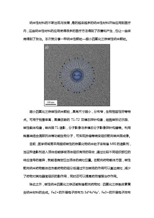
超小四氧化三铁磁性纳米颗粒
纳米性材料的不断出现与发展,是的越来越多的纳米性材料开始应用到医疗内,这些纳米性材料的应用使得很多的医疗方法得到了改善和产生,也让一些疾病得到了救治。
本次就分享一种纳米性颗粒—超小四氧化三铁磁性纳米颗粒。
超小四氧化三铁磁性纳米颗粒,具有尺寸超小,分布窄,生物相容性好等特点。
可用于弛豫率高,聚集依赖的T1-T2双模态探针构建,细胞磁标记示踪、磁性载体构建,磁共振T1造影,分子影像与多模态分子影像探针构建等。
利用羧基端结合偶联抗体等功能生物分子,可实现肿瘤等病变组织靶向磁共振成像。
目前,医学领域常采用超顺磁性的铁氧化物纳米粒子来制备MRI的造影剂,当这种造影剂进入活体后能够被活体组织有效的吸收,通过比较不同组织部位的响应信号的差异,就能准确定位出活体的病灶位置。
在靶向药物载体方面,磁性靶向纳米药物载体在负载药物的组分后通过外加磁场的作用可以直达病灶,减少了药物对其他器官组织的副作用,同时还可以提高药效增强治疗作用。
除此之外,磁性纳米四氧化三铁还能制备靶向药物如:四氧化三铁槲皮素复合纳米材料的合成。
Fe2+的外层电子排布为3d°4s°4p", Fe3+的外层电子排布为3d54s04p0在纳米四氧化三铁的内部,存在很多Fe2+和Fe3+,它们的4s和4p都是空轨道。
槲皮素分子中的羟基氧原子的外层电子排布为2p%,除和苯环及氢原子相连的两个电子,还剩一个孤对电子,因此槲皮素羟基上的氧原子活化后,可以提供孤对电子给Fe2+和Fe3+的空轨道,形成配位键结合。
Fe2+或者Fe3+的4s和4p轨道都是空轨道,能够接受孤对电子对,从而与两个氧原子结合。
以上是对超小四氧化三铁磁性纳米颗粒的相关介绍,下面介绍一家生产纳米材料的公司。
南京东纳生物科技有限公司是一家集产学研于一体的高新技术型企业,主要从事纳米材料及生物医学纳米技术,功能微球、体外诊断试剂与仪器等研发与生产。
公司拥有一批包括多名创业教授、博士后、博士及硕士的自主研发队伍,同时广泛联合各知名高校院所及医院的专家团队。
制备方法介绍之-四氧化三铁纳米颗粒(含多种纳米复合材料产品)
制备方法介绍之-四氧化三铁纳米颗粒(含多种纳米复合材料产品)Fe3O4磁性纳米颗粒由于同时具备磁性颗粒和纳米颗粒的双重优势,已经广泛应用于靶向药物载体,细胞分离,核磁共振,免疫分析,核酸杂交等生物医学领域。
同时,这种超顺磁性材料在催化领域也具有很好的应用前景,可以作为液相小尺寸催化剂的催化载体,改善催化剂分离难的状况,但是Fe3O4磁性纳米粒子易氧化,比表面积较高,具有强烈的聚集倾向,难以直接应用.采用无定型SiO2对Fe3O4磁性纳米粒子进行表面包覆,SiO2包覆层增加了其化学稳定性,同时SiO2的无毒性和表面羟基的存在提高了其生物相容性,拓宽了Fe3O4磁性纳米粒子在生物,催化等领域的应用。
1.Fe3O4磁性纳米颗粒的制备:常温下将2.16gFeCl3·6H2O溶解于100ml去离子水中,在氮气保护下加入Na2SO3溶液,磁力搅拌15min,快速加入5ml质量分数为25%-28%的浓氨水,溶液迅速变黑,在60℃油浴中反应30min,然后逐滴加入0.3g的柠檬酸,调节温度值80℃,反应1h,之后冷却室温,沉降磁球,用丙酮和去离子水清洗磁球数次,后在去离子水中超声分散,得到的就是稳定的Fe3O4磁性纳米颗粒。
2.油相Fe3O4磁性纳米颗粒的制备:在磁性材料合成中,油酸是以后总常用的纳米颗粒稳定剂。
采用热解油酸铁复合物制备Fe3O4磁性纳米颗粒,并通过透射电子显微镜(TEM),X-射线粉末衍射仪(X-RD)和振动样品磁强计(VSM)对其进行表征。
得到的Fe3O4磁性纳米颗粒呈球形,在室温下具有超顺磁,并且由于油酸的稳定作用,纳米颗粒在正己烷等非极性溶剂中具有良好的分散性。
3.Fe3O4@SiO2纳米粒子制备:以O P-10,正丁醇,环己烷和浓氨水分别作为表面活性剂,助表面活性剂,油相和水相,按一定的比例混合配成微乳液体,剧烈搅拌,再依次加入酸洗处理过的Fe3O4胶体溶液和TEOS,反应完成后使用体积比为 75 %的丙酮水溶液破乳,静置分层后,去除上清液,对下层沉淀物用乙醇清洗数次,后得到Fe3O4@SiO2磁性纳米复合粒子。
纳米四氧化三铁的应用
纳米四氧化三铁的应用一、纳米四氧化三铁的简介四氧化三铁是一种常用的磁性材料,又称氧化铁黑,呈黑色或灰蓝色。
四氧化三铁是一种铁酸盐,即Fe2+Fe3+(Fe3+O4)(即FeFe(FeO4)前面2+和3+代表铁的价态)。
在Fe3O4里,铁显两种价态,一个铁原子显+2价,两个铁原子显+3价,所以说四氧化三铁可看成是由FeO与Fe2O3组成的化合物,可表示为FeO·Fe2O3,而不能说是FeO与Fe2O3组成的混合物,它属于纯净物。
化学式:Fe3O4,分子量231.54,硬度很大,具有磁性,可以看成是氧化亚铁和氧化铁组成的化合物。
逆尖晶石型、立方晶系,密度 5.18g/cm3。
熔点1867.5K(1594.5℃)。
它不溶于水,也不能与水反应。
与酸反应,不溶于碱,也不溶于乙醇、乙醚等有机溶剂。
在外磁场下能够定向移动,粒径在一定范围之内具有超顺磁性,以及在外加交变电磁场作用下能产生热量等特性,其化学性能稳定,因而用途相当广泛。
纳米四氧化三铁置于介质中,采用胶溶化法和添加改性剂及分散剂的方法,通过在颗粒表面形成吸附双电层结构阻止纳米粒子团聚,制备稳定分散的水基和有机基纳米磁性液体。
制备的磁性液体2~12个月都能很好的分散着,磁性液体中颗粒平均粒径为16~35nm之间。
通过大量实验,确定了最佳的工艺配方和工艺路线,工艺简单安全,能耗低,并保持了磁性颗粒的粒径在纳米量级,并且经磁性能测试可得磁性颗粒具有超顺磁性,其技术指标达到并超过国内外磁性纳米四氧化三铁性能,为国内各种磁流体的应用提供了基础。
二、纳米四氧化三铁的配置方法由于纳米四氧化三铁特殊的理化学性质 , 使其在实际应用中越来越广泛 , 而其制备方法和性质的研究也得到了深入的进展。
磁性纳米微粒的制备方法主要有物理方法和化学方法。
物理方法制备纳米微粒一般采用真空冷凝法、物理粉碎法、机械球磨法等。
但是用物理方法制备的样品一产品纯度低、颗粒分布不均匀 , 易被氧化 , 且很难制备出10nm 以下的纳米微粒 , 所以在工业生产和试验中很少被采纳。
四氧化三铁

四氧化三铁二氧化锰核壳结构纳米颗粒

四氧化三铁二氧化锰核壳结构纳米颗粒一、介绍四氧化三铁二氧化锰核壳结构纳米颗粒(Fe3O4@MnO2 NPs)是一种具有潜在应用前景的纳米材料,具有许多独特的性质和应用。
本文将从结构、性质、制备方法和应用等方面全面介绍这类纳米颗粒。
二、结构分析Fe3O4@MnO2 NPs通常由内部的四氧化三铁(Fe3O4)核和外部的二氧化锰(MnO2)壳组成。
核壳结构的设计使得这种纳米颗粒既具有Fe3O4的磁性,又具有MnO2的高电化学活性和催化性能。
核壳结构的形成对于纳米颗粒的性能起着至关重要的作用。
三、性质分析1. 磁性:Fe3O4@MnO2 NPs具有良好的磁性,可以用于磁性分离和靶向药物输送等领域。
2. 电化学活性:由于MnO2壳的存在,这种纳米颗粒具有优异的电化学活性,可应用于超级电容器和锂离子电池等领域。
3. 催化性能:Fe3O4@MnO2 NPs在催化剂方面表现出色,可用于有机废水处理、氧化还原反应等。
四、制备方法目前,制备Fe3O4@MnO2 NPs的方法主要有物理合成和化学合成两种。
物理合成常用的方法包括热分解法和溶剂热法,而化学合成主要是通过共沉淀法和水热法制备。
不同的制备方法会影响纳米颗粒的结构和性能,因此需要选择合适的方法加以研究和应用。
五、应用展望Fe3O4@MnO2 NPs的独特性质使得它在生物医药、环境保护、能源存储等领域具有广泛的应用前景。
可以用于肿瘤治疗的磁热疗法、超级电容器的电极材料、有机废水的催化降解等。
六、个人观点作为一种新型纳米材料,Fe3O4@MnO2 NPs的研究具有重要意义。
我认为,未来可以继续深入探讨其在生物医药领域的应用,尤其是靶向治疗和肿瘤诊断等方面的研究。
七、总结Fe3O4@MnO2核壳结构纳米颗粒作为一种具有潜在应用前景的纳米材料,在磁性、电化学活性、催化性能等方面具有独特优势。
未来的研究应该更加注重其制备方法与性能的相关性、在生物医药领域的应用前景和环境友好型等方面的研究。
四氧化三铁纳米颗粒氧化
四氧化三铁纳米颗粒氧化
四氧化三铁纳米颗粒是一种常见的纳米材料,其化学式为
Fe3O4。
这种纳米颗粒通常具有较小的尺寸,通常在10-100纳米之间。
它们具有许多有趣的性质和潜在的应用,其中包括在医学领域中作为对癌症的治疗和诊断的磁性纳米颗粒、在环境领域中作为污染物的吸附剂和催化剂,以及在电子领域中作为磁性材料等。
在氧化过程中,四氧化三铁纳米颗粒会与氧气发生反应,生成氧化铁。
这种氧化反应可以通过加热四氧化三铁纳米颗粒或者将其暴露在氧气环境中来实现。
氧化后的产物通常是氧化铁,化学式为Fe2O3。
氧化后的纳米颗粒可能会具有不同的性质和应用,因此氧化过程对于调控纳米颗粒的性质和功能具有重要意义。
除了化学反应,氧化还可以指四氧化三铁纳米颗粒在空气中发生氧化腐蚀的过程。
在这种情况下,四氧化三铁纳米颗粒的表面会与氧气发生反应,形成氧化层。
这种氧化层可能会影响纳米颗粒的磁性、光学性质等方面,因此对于纳米颗粒的稳定性和应用也具有重要影响。
总的来说,四氧化三铁纳米颗粒的氧化过程是一个复杂而重要
的问题,涉及到纳米材料的制备、性质调控和应用等多个方面。
通过深入研究氧化过程,可以更好地理解和利用这些纳米颗粒在各个领域的潜在应用价值。
纳米材料的介绍及纳米四氧化三铁的制备方法介绍
纳米材料的介绍及纳米四氧化三铁的制备方法介绍沈明09应化(2)班20091302232摘要本文阐述了纳米材料的性能特点。
然后以纳米四氧化三铁为例,介绍了其在磁性材料、多功能材料、催化材料以及医学领域的应用现状。
着重介绍了纳米四氧化三铁的制备方法,如沉淀法、溶胶-凝胶法、微乳液法等做了介绍,并对各制备方法进展和优缺点进行了简要介绍。
最后对纳米四氧化三铁今后的发展做了展望。
关键词:纳米材料;四氧化三铁;应用;制备;进展前言纳米科学技术是研究在千万分之一米到十亿分之一米内,原子、分子和其他类型物质的运动和变化的科学。
在这一尺度范围内对原子、分子进行操纵和加工的技术,称为纳米技术。
纳米材料是一种介于分子与宏观材料之间的介观态材料,一般由金属、金属化合物、无机物或聚合物的纳米级颗粒(1~100nm)经压实或烧结而成的材料。
纳米级颗粒在整体上构成了一种与晶态或玻璃态有较大差别的崭新结构,导致它具有一系列的特殊物理、化学性质,而这些特性是其他固体材料或常规材料根本不具有的特性。
目前,人工已经合成并研究的单质体系有:Fe、Si、Pd、Cu、Ti、Ni、Al、Mo等;单一氧化物有Al2O3、MgO、ZrO2、Fe2O3、TiO2等;多组分复合纳米材料有CoFe2O4、MnFe2O4等。
一、纳米和纳米复合材料的应用纳米材料的研究和应用,不但改造了传统材料,而且又源源不断地创造出新材料,从而提高和改变了我们的生活质量。
1、纳米级磁性材料纳米微粒尺寸小,具有单磁畴结构、矫顽力高的特性,用它制成的磁记录材料不仅音质、图像和信噪比较好,而且记录密度比γ- Fe2O3高几十倍。
日本松下电器公司已制成纳米级微型录像带,具有图象清晰、信噪比较高、失真小等优点。
此外,超顺磁的强磁性纳米颗粒还可以制成磁性液体,广泛用于声电器材、阻尼器材、旋转密封、润滑、选矿等领域。
2、纳米陶瓷纳米陶瓷的晶粒度尺寸极小,晶粒容易在其他颗粒上运动,具有极高的强度、韧性及延展性。
四氧化三铁
Synthesis,magnetic and electromagnetic wave absorption properties of porous Fe3O4/Fe/SiO2core/shell nanorodsY.J.Chen,1,a͒P.Gao,1C.L.Zhu,1R.X.Wang,1L.J.Wang,1M.S.Cao,2,b͒andX.Y.Fang21College of Science,and College of Material Science and Chemical Engineering,Harbin EngineeringUniversity,Harbin15001,China2School of Materials Science and Engineering,Beijing Institute of Technology,Beijing100081,China͑Received12April2009;accepted22July2009;published online2September2009͒Porous Fe3O4/Fe/SiO2core/shell nanorods were fabricated,in which the diameter of the pores was5–30nm.The magnetic and electromagnetic properties were investigated.The temperaturedependent magnetic measurements showed that these nanorods were ferromagnetic with a Verweytemperature of129K.The electromagnetic data indicated that effective complementarities betweenthe dielectric loss and the magnetic loss were realized,suggesting that they have excellentelectromagnetic wave absorption properties.Thus the porous core/shell nanorods could be used asa kind of candidate absorber.©2009American Institute of Physics.͓doi:10.1063/1.3204958͔Electromagnetic͑EM͒wave absorption materials have attracted much attention due to the expanded EM interfer-ence problems.Now the EM absorbers are being studied to have more advantages such as lightweight,wide absorption frequency,high thermal stability,and antioxidation.Re-cently,some one-dimensional͑1D͒nanostructures have been reported for the attenuation of EM wave.These materials are involved with carbon nanotubes͑CNTs͒,iron and zinc ox-ides,etc.1–5However,the attenuation mechanism of those materials is mainly based on either dielectric loss or mag-netic loss.Core/shell nanostructures have shown exciting physical properties and/or different physical properties over the single-component counterparts and thus have aroused wide research interests.Recently many nanocomposites con-taining magnetic cores have been developed to attenuate EM wave in terms of different mechanisms from those of the conventional absorbers.For example,CNTsfilled with mag-netic particles,6,7ZnO-coated iron nanocapsules,8and carbon-coated nickel nanocapsules9have been developed to attenuate EM wave because those materials exhibit good complementarities between the dielectric loss and the mag-netic loss.Lee and Chen10synthesized Ni/Ag core/shell nanoparticles and found an additional absorption of the com-posites related to the lags of polarization between the core/ shell interfaces.Thus the interface in the composites may have an important effect on the EM wave absorption prop-erty,especially toward EM wave in high frequency range.In addition,it has been reported that insulator-coated magnetic materials can be used effective absorbers because magnetic materials are well separated,and thus the eddy current loss is largely reduced.11,12Therefore,core/shell structures contain-ing magnetic materials are very promising for attenuating EM wave.Fe3O4materials with a high Curie temperature and half metallic properties have wide applications in tunneling mag-netoresistance devices,sensor,magnetic data storage,ferrof-luid,and biomedicalfields.13–16Recently,Fe3O4films on hollow glass spheres have been reported to be used as ab-sorbers for EM wave.17However,there are few reports on the synthesis and EM properties of1D Fe3O4 nanostructures,13,18especially for porous Fe3O4nanostruc-tures.Herein,we report on the synthesis and magnetic and EM wave absorption properties of porous Fe3O4/Fe/SiO2 core/shell nanorods.Porous Fe3O4/Fe/SiO2core/shell nanorods were fabri-cated via the following process.͑1͒-FeOOH nanorods were first fabricated by a hydrothermal route,which was described in Refs.14and15.͑2͒-FeOOH/SiO2nanorods were then obtained by the hydrolysis of tetraethyl orthosilicate.16After annealing the composites at500°C for3h,␣-Fe2O3/SiO2 nanorods were fabricated.͑3͒Porous Fe3O4/Fe/SiO2core/ shell nanorods were produced by annealing␣-Fe2O3/SiO2at 400°C for5h under a continuous N2/H2gasflow.After H2 deoxidation,the color of sample changed from yellow to black.Products were characterized with x-ray powder dif-fraction͑XRD;D/MAX2500,Cu K␣radiation͒,scanning electron microscopy͑JEOL JSM6700F͒,and transmission electron microscopy͑TEM;JEOL2010͒.The magnetic properties were investigated on a superconducting quantum interference device͑SQUID͒magnetometer.For EM mea-surement,65wt%of porous Fe3O4/Fe/SiO2core/shell na-norods was added into wax matrix.The complex permittivity and permeability of the composites were measured by using the T/R coaxial line method.The measurement setup con-sisted of an HP8722ES vector network analyzer with a syn-thesized sweep oscillator source and an S-parameter test set.The bottom spectrum in Fig.1shows the XRD pattern of the as-synthesized␣-Fe2O3/SiO2core/shell -pared with the data in Ref.19,all peaks in the pattern can be indexed to the rhombohedra structure of␣-Fe2O3.The upper spectrum is the XRD pattern of the porous Fe3O4/Fe/SiO2 core/shell nanorods.In this pattern,main peaks indicated by Miller indices come from cubic crystal structure of Fe3O4 according to Ref.20.In addition,two other peaks are alsoa͒Author to whom correspondence should be addressed.Electronic mail:chenyujin@.b͒Electronic mail:caomaosheng@.JOURNAL OF APPLIED PHYSICS106,054303͑2009͒0021-8979/2009/106͑5͒/054303/4/$25.00©2009American Institute of Physics106,054303-1found in the pattern.They can be indexed to ␣-Fe according to the data in Ref.21.Relatively weak intensity of the peaks may indicate that there are small amount of ␣-Fe in the com-posites.Figure 2͑a ͒is a typical TEM image of as-synthesized ␣-Fe 2O 3/SiO 2core/shell nanorods.It is clearly seen that the SiO 2shell with a thickness of ϳ25nm is very uniform,and an average diameter and length of the core/shell nanorods are 80nm and 1.0m,respectively.The ␣-Fe 2O 3core has many nanopores along axis direction,and the diameters of those pores range from 5to 30nm,as shown in Fig.2͑b ͒.Figure 2͑c ͒shows a high-resolution TEM image ͑HRTEM ͒of the porous ␣-Fe 2O 3core.Clear lattice fringes are ob-served in the image,suggesting a crystal nature of the nano-rods.The space between neighborhood lattices is 0.364nm,corresponding to ͑012͒planes of ␣-Fe 2O 3.The selective-area electron diffraction ͑SAED ͒pattern ͓the inset of Fig.2͑c ͔͒further confirms the crystal nature of the ␣-Fe 2O 3core.After H 2deoxidation,the porous ␣-Fe 2O 3/SiO 2com-posites were transformed into Fe 3O 4/Fe /SiO 2core/shell na-norods.Figure 3͑a ͒is a TEM image of the as-synthesized Fe 3O 4/Fe /SiO 2core/shell nanorods.From this figure,it can be seen that the nanorods have similar morphology and size of the ␣-Fe 2O 3/SiO 2core/shell nanorods.Importantly,theFe 3O 4/Fe /SiO 2core/shell nanorods still remain porous char-acteristics.Figure 3͑b ͒is the HRTEM image of the pore located in the center of the nanorods in which the space of crystal lattice is about 0.252nm,corresponding to ͑311͒plane of cubic Fe 3O 4.The HRTEM image in the outer region of the core/shell nanorods was also taken for further struc-tural characterization,as shown in Fig.3͑c ͒.Different lattice fringes are observed in different areas in the figure.The space between neighborhood lattices at inner side is 0.214nm,corresponding to ͑400͒plane of cubic Fe 3O 4.It reveals a crystal nature of porous Fe 3O 4core,which is confirmed by the corresponding SAED pattern ͓the inset of Fig.3͑c ͔͒.On the contrary,the space between neighborhood lattices at the outer side connected with Fe 3O 4is 0.201nm,corresponding to ͑110͒plane of ␣-Fe.The width of ␣-Fe is about 3nm,which reveals small amount of ␣-Fe presented in the com-posites.In addition,SiO 2still remains amorphous even after H 2deoxidation because no crystal lattice is observed in the outermost shell region.The results above demonstrate that porous Fe 3O 4/Fe /SiO 2core/shell nanorods can be obtained after H 2deoxidation of ␣-Fe 2O 3/SiO 2nanocomposites.It should be noted that the porous nanorods cannot be fabri-cated without SiO 2coatings.The inset of Fig.3͑a ͒shows a typical TEM image of the products obtained by H 2deoxida-tion of ␣-Fe 2O 3nanorods at 360°C for 6h.It can be seen that the products are mainly compared of particles with a diameter of ϳ200nm.This result demonstrates that the SiO 2shell plays a very important role in the synthesis of the porous Fe 3O 4/Fe /SiO 2core/shell nanorods.Fe 3O 4is an important magnetic material,and its mag-netic properties ͑ferromagnetic or superparamagnetic charac-teristics ͒can be tuned by the size and the ambient tempera-ture.Therefore,we used the SQUID technique to investigate the temperature dependent magnetic properties of the core/shell nanorods.Figure 4displays the field-cooled ͑FC ͒and zero-field-cooled ͑ZFC ͒magnetization ͑M ͒versus tempera-ture curves,with an applied external field ͑H ͒of 300Oe.An apparent magnetic transition around 129K is observed,which corresponds to the Verwey transition.22It arises fromaFIG.1.XRD patterns of the porous ␣-Fe 2O 3/SiO 2and Fe 3O 4/Fe /SiO 2core/shellnanorods.FIG.2.The micrographs of the porous Fe 3O 4/Fe /SiO 2core/shell nanorods.͑a ͒TEM image,͑b ͒a magnified TEM image,and ͑c ͒HRTEM image of the ␣-Fe 2O 3core.FIG.3.͑a ͒TEM image of the porous Fe 3O 4/Fe /SiO 2core/shell nanorods.The inset:TEM image of the products without SiO 2shells;scale bar:200nm.͑b ͒TEM image of a pore in Fe 3O 4/Fe /SiO 2core/shell structures.͑c ͒HRTEM image of the core;the inset:the corresponding SAED pattern.fast electron hopping process between Fe 3+and Fe 2+ions in the core/shell nanorods.The Verwey transition is a special character of magnetite,which confirms that our sample con-tains Fe 3O 4.The field dependence of magnetization for the porous Fe 3O 4/Fe /SiO 2core/shell nanorods was also mea-sured,as shown in the inset of Fig.4.Significant hysteresis loops in the M -H curve indicate the ferromagnetic behavior of the core/shell nanorods.The saturation magnetization ͑M s ͒,coercivity ͑H c ͒,and retentivity ͑M r ͒are 59.22emu/g,265.77Oe,and 10.515emu/g,respectively.The M s of the core/shell nanorods is slightly lower than that of Fe 3O 4nanocubes due to the presence of the SiO 2shells in the nanocomposites;23,24however,the H c value is relatively higher.Both Fe 3O 4and ␣-Fe have shown excellent EM proper-ties and can be used as efficient EM absorbers.Herein,65wt %of the porous nanorods was dispersed into wax matrix in order to investigate their EM properties.Figure 5͑a ͒shows the frequency dependence of the real part ͑Ј͒and imaginary part ͑Љ͒of relative complex permittivity ͑r =Ј−j Љ͒of the porous Fe 3O 4/Fe /SiO 2core/shell nanorods.It can be foundthat the values of Јand Љare in the range of 6.25–6.96and 0.37–0.89,respectively,over 2–18GHz frequency range.Јreduces slightly between 2and 17GHz and then slightly increases.On the contrary,Љincreases slightly between 2and 17GHz and then slightly decreases.This phenomenon can be explained by the fact that both real permittivity and imaginary permittivity are correlated.Figure 5͑b ͒shows the relative complex permeability ͑r =Ј−j Љ͒of the porous Fe 3O 4/Fe /SiO 2core/shell nanorods.It reveals that the real part ͑Ј͒first increases,then decreases at 2–8GHz range,and increases gradually at 8–17GHz.Meanwhile,the image part ͑Љ͒first increases and then declines gradually at 2–17GHz range.Generally,the excellent EM wave absorptions are strongly dependent on the efficient complementarities be-tween the relative permittivity and permeability.Only mag-netic loss or only dielectric loss leads to weak EM attenua-tion.Therefore,we calculate the tangent losses based on the data in Figs.5͑a ͒and 5͑b ͒,and the calculated results are shown in Fig.5͑c ͒.It can be found that the value of tan ␦m and tan ␦e vary in the ranges of 0.04–0.28and 0.06–0.13,respectively,over 2–18GHz range.The magnetic loss is dominant at a low frequency range ͑2–9.7GHz ͒,whereas the dielectric loss becomes important at a high frequency range ͑9.7–17GHz ͒.It demonstrates that the porous Fe 3O 4/Fe /SiO 2core/shell nanorods have better complemen-tarities between the dielectric loss and the magnetic loss,which suggests they have excellent EM wave absorption properties.The dielectric loss is mainly dependent on the space charge polarization and the dipole one.The former is proven to be not important at a high frequency regime.25Thus the latter is a dominant mechanism of the dielectric loss.The dipole polarization can arise from the process elec-tron transfer between Fe 2+and Fe 3+ions in the nanorods.In addition,lags of polarization at the core/shell interfaces as the frequency also contribute to the dielectric loss,which is similar to those in ZnO-coated iron nanocapsules,carbon-coated nickel nanocapsules,and Ni/Ag core/shell nanoparticles.8–10As for the magnetic loss,the contribution of the natural resonation can be excluded in Fe 3O 4/Fe /SiO 2core/shell nanorods because no resonance peak is observed in the permeability curves ͓Figs.5͑a ͒and 5͑b ͔͒.The previous measurements ͑Fig.4͒show the core/shell nanorods are fer-romagnetic,and the multidomain magnetic structure should be presented in the nanorods due to their special 1D mor-phology and their large sizes.Therefore,magnetic hysteresis and domain-wall displacement are ascribed to the magnetic loss.In addition,a large amount of nanopores in the core/shell nanorods may lead to the energy dissipation when the EM wave propagates among the magnetic media and free space ͑pores ͒.26,27However,the pores are too tiny in com-parison to the wavelength of EM wave,and thereby the ef-fect of the pores on EM wave attenuation is not exactly de-termined at the present experiment.The results above demonstrate that the porous Fe 3O 4/Fe /SiO 2core/shell nanorods may have good EM wave absorption properties.To further clarify it,the reflec-tion loss ͑R L ͒is calculated,as shown in Fig.5͑d ͒,according to the transmit-line theory.28It indicates that themaximumFIG.4.ZFC and FC curves at 300Oe of the porous Fe 3O 4/Fe /SiO 2core/shell nanorods ͑inset:hysteresis loops of the nanorods at room temperature ͒.FIG.5.͑Color online ͒EM properties of the porous Fe 3O 4/Fe /SiO 2core/shell nanorods.͑a ͒Frequency dependence of the real part and imaginary part of the complex permittivity.͑b ͒Frequency dependence of the real part and imaginary part of the complex permeability.͑c ͒The relationships be-tween tan ␦e and tan ␦m .͑d ͒The reflection loss for the nanocomposites with thickness of 2–5mm.reflection loss reaches16.86dB at11.36GHz,and the ab-sorption range underϪ10dB is from8.5to15.4GHz,i.e.,the bandwidth with the reflection loss belowϪ10dB is up to6.96GHz,with2mm in thickness of the absorbers.Addi-tionally,the maximum reflection loss obviously shifts tolower frequency range with increasing the thickness and in-creases to18.6dB with d=5mm.The microwave absorp-tion properties are better than those of ZnO nanowires re-ported in our previous literatures,5Fe microwires,4and CNTs ͑Ref.7͒and are comparable to CNT/CoFe2O4 nanocomposites.7It demonstrates that the porousFe3O4/Fe/SiO2core/shell nanorods are attractive for EM wave absorptive materials.In summary,the porous Fe3O4/Fe/SiO2core/shell nano-rods,in which the SiO2shell with a thickness ofϳ25nm is very uniform and the average diameter and length of the core/shell nanorods are80nm and1.0m,respectively,are successfully fabricated.The temperature dependent magnetic measurements show that these nanorods are ferromagnetic with a Verwey temperature of129K.The EM data demon-strate that the bandwidth with the reflection loss belowϪ10 dB is up to6.96GHz,with2mm in thickness of the absorb-ers.Thus the porous core/shell nanorods could be used as a kind of candidate absorber.This work was supported by the National Natural Sci-ence Foundation of China͑Grant No.50772025͒,projectsupported by the Ministry of Science and Technology ofChina͑Grant No.20080420͒,China Postdoctoral ScienceFoundation͑Grant Nos.20060400042and200801044͒,theNatural Science Foundation of Heilongjiang Province,China ͑Grant Nos.F200828and E200839͒,and also the Specialized Research Fund for the Doctoral Program of Higher Educa-tion of China͑Grant No.20070217002͒.1P.C.P.Watts,W.K.Hsu,A.Barnes,and B.Chambers,Adv.Mater.͑Weinheim,Ger.͒15,600͑2003͒.2A.Wadhawan,D.Garrett,and J.M.Perez,Appl.Phys.Lett.83,2683͑2003͒.3L.J.Deng and M.Han,Appl.Phys.Lett.91,023119͑2007͒.4J.R.Liu,M.Itoh,M.Terada,T.Horikawa,and K.I.Machida,Appl.Phys. Lett.91,093101͑2007͒.5Y.J.Chen,M.S.Cao,T.H.Wang,and Q.Wan,Appl.Phys.Lett.84,3367͑2004͒.6R.C.Che,L.M.Peng,X.F.Duan,Q.Chen,and X.L.Liang,Adv.Mater.͑Weinheim,Ger.͒16,401͑2004͒.7R.C.Che,C.Y.Zhi,C.Y.Liang,and X.G.Zhou,Appl.Phys.Lett.88, 033105͑2006͒.8X.G.Liu,D.Y.Geng,H.Meng,P.J.Shang,and Z.D.Zhang,Appl.Phys. Lett.92,173117͑2008͒.9X.F.Zhang,X.L.Dong,H.Huang,Y.Y.Liu,W.N.Wang,X.G.Zhu,B. Lv,J.P.Lei,and C.G.Lee,Appl.Phys.Lett.89,053115͑2006͒.10C.C.Lee and C.H.Chen,Appl.Phys.Lett.90,193102͑2007͒.11J.R.Liu,M.Itoh,M.Terada,K.I.Machida,S.Sugimoto,and T.Maeda, J.Appl.Phys.98,054305͑2005͒.12X.G.Liu,D.Y.Geng,and Z.D.Zhang,Appl.Phys.Lett.92,243110͑2008͒.13D.H.Zhang,Z.Q.Liu,S.Han,C.Li,B.Lei,M.P.Stewart,J.M.Tour, and C.W.Zhou,Nano Lett.4,2151͑2004͒.14S.H.Gee,Y.K.Hong,D.W.Erickson,M.H.Park,and J.C.Sur,J.Appl. Phys.93,7560͑2003͒.15T.Sen,A.Sebastianelli,and J.Bruce,J.Am.Chem.Soc.128,7130͑2006͒.16H.Zeng,J.Li,J.P.Liu,Z.L.Wang,and S.H.Sun,Nature͑London͒420, 395͑2002͒.17J.Wei,J.H.Liu,and S.M.Li,J.Magn.Magn.Mater.312,414͑2007͒. 18Z.Q.Liu,D.H.Zhang,S.Han,C.Li,B.Lei,W.G.Lu,J.Fang,and C. W.Zhou,J.Am.Chem.Soc.127,6͑2005͒.19JCPDS Card No.33-0664.20JPCDS Card No.72-2303.21JCPDS Card No.06-0696.22E.J.W.Verwey,Nature͑London͒144,327͑1939͒.23H.T.Yang,T.Ogawa,D.Hasegawa,and M.Takahashi,J.Appl.Phys. 103,07D526͑2008͒.24C.Kittel,Phys.Rev.73,155͑1948͒.25M.H.Abdullah and A.N.Yusoff,J.Mater.Sci.32,5817͑1997͒.26X.Tang,Q.Tian,B.Y.Zhao,and K.Hu,Mater.Sci.Eng.,A445–446, 135͑2007͒.garkov,S.M.Matytsin,K.N.Rozanov,and A.K.Sarychev,J. Appl.Phys.84,3806͑1998͒.es,W.B.Westphal,and A.von Hippel,Rev.Mod.Phys.29,279͑1957͒.。
磁性四氧化三铁纳米粒子的合成及改性
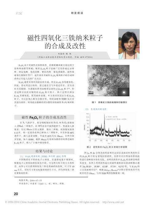
21
结论
本 文 首 先 利 用 化 学 共 沉 淀 法 合 成 了 纳 米 级 的 Fe3O4 粒 子 , 在合成过程中, 氨水要保证是过量的, 因为要想得到较纯的 Fe3O4, Fe2+要完全沉淀, 溶液的 pH 值 必 须 一 直 保 持 大 于 等 于 8.9, 并一 定 要 保 持 高 速 搅 拌 , 这 样 粒 子 才 能 达 到 纳 米 级 。 用 油 酸 和 SDBS 两 种 表 面 活 性 剂 对 合 成 好 的 Fe3O4 粒 子 进 行 改
(4) 改性前后 Fe3O4 透射电镜分析
图 4 Fe3O4 改性前 (a) 后 (b) 的透射电镜照片
图 4a 和 4b 分别是改性前后的 Fe3O4 透射电镜照片, 从图 4a 中 可 以 明 显 看 出 改 性 前 的 Fe3O4 粒 子 之 间 因 存 在 粒 子 间 的 作用力而引起的粒子聚集状况, 而改性后的粒子却有着较好 的分散性。 用双层表面活性剂改性后的 Fe3O4 粒子, 由于表面 被双层表面活性剂所包覆, 因而粒子之间会产生静电斥力, 使得粒子在溶剂中均匀分散而不聚集。
参考文献
〔1〕 Tricot, et al. Process for the preparation of magnetic beads of vinylaromaticpolymers 〔S〕 . USP4 339 337, 1982
〔2〕 Hiromichi Noguchi, Noriko Yanase, Yasuzo Uchida, et al. Preparation and characterization by thermal analysis of magnetic latex particles 〔J〕 .Appl Polym Sci,1993,48:1593~ 1597
纳米材料-Fe3O4磁性纳米粒
• 68•山东化工SHANDONG CHEMICAL INDUSTRY2017年第46卷纳米材料-Fe304磁性纳米粒席静,胡久平(兰州石化职业技术学院应用化学工程学院,甘肃兰州730060)摘要:纳米科学是一个正在蓬勃发展的学科,它的发展对其他科学领域都有重要的影响,其中有一大领域的纳米粒子已经近被人们广泛 研究,Fe304磁性纳米粒就是其中较为典型的一个代表。
它在构建生物传感器、光学传感器、电化学传感器等领域都有重要的应用。
关键词:Fe304磁性纳米粒;制备;应用中图分类号:TB383 文献标识码:A文章编号:1008 -021X(2017)21 -0068 -02A Kind of Nanometer Materials -Fe304Magnetic NanoparticlesXi Jin g, Hu Jiuping(Application of Chemical Engineering,Lanzhou Petrochemical College of Vocational Technology,Lanzhou730060,China)Abstract:Nanoscience is a vigorous development discipline,its development has the important influence to other scientific fields,and it has been widely studied by human,the Fe304magnetic nanoparticles is a typical represents.It have important applications in biological marker,sensors,optical probe,constructing the electrochemical probes and so on.Key words:Fe304magnetic nanoparticles;preparation;application磁性纳米材料是是指尺寸在1 ~ 100 n m范围内的磁性金 属或金属氧化物材料,它是纳米材料的一个重要的组成部分。
四氧化三铁
G ModelMAC-14751;No.of Pages 5Materials Chemistry and Physics xxx (2011) xxx–xxxContents lists available at ScienceDirectMaterials Chemistry andPhysicsj o u r n a l h o m e p a g e :w w w.e l s e v i e r.c o m /l o c a t e /m a t c h e m p h ysMaterials science communicationStructure and electrochemical performance of Fe 3O 4/graphene nanocomposite as anode material for lithium-ion batteriesGang Wang a ,Ting Liu a ,Xiaoling Xie a ,Zhaoyu Ren b ,Jinbo Bai c ,Hui Wang a ,∗aKey Laboratory of Synthetic and Natural Functional Molecule Chemistry (Ministry of Education),College of Chemistry &Materials Science,Northwest University,Xi’an 710069,PR China bNational Key Laboratory of Photoelectric Technology and Functional Materials (Culture Base),National Photoelectric Technology and Functional Materials &Application International Cooperation Base,Institute of Photonics &Photon-Technology,Northwest University,Xi’an 710069,PR China cLab.MSS/MAT,CNRS UMR 8579,Ecole Centrale Paris,92295Chatenay Malabry,Francea r t i c l e i n f o Article history:Received 25August 2010Received in revised form 7January 2011Accepted 21March 2011Keywords:Composite materials Chemical synthesisElectrochemical techniques Electrochemical propertiesa b s t r a c tUsing hydrothermal method,Fe 3O 4/graphene nanocomposite is prepared by synthesizing Fe 3O 4par-ticles in graphene.The synthesized Fe 3O 4is nano-sized sphere particles (100–200nm)and uniformly distributed on the planes of graphene.Fe 3O 4/graphene nanocomposite as anode material for lithium ion batteries shows high reversible specific capacity of 771mAh g −1at 50th cycle and good rate capability.The excellent electrochemical performance of the nanocomposite can be attributed to the high surface area and good electronic conductivity of graphene.Due to the high surface area,graphene can prevent Fe 3O 4nanoparticles from aggregating and provide enough space to buffer the volume change during the Li insertion/extraction processes in Fe 3O 4nanoparticles.© 2011 Elsevier B.V. All rights reserved.1.IntroductionNano-and micron-sized metal oxides (MO,M =Fe,Co,Cu,etc.)have been widely investigated as promising anode materials for lithium-ion batteries (LIBs)[1–6].Among them,Fe 3O 4has attracted significant research attention due to its fascinating properties such as high theoretical capacity (928mAh g −1),low cost and low envi-ronmental impact [6].But the Fe 3O 4anode materials have poor cycle performance because of agglomerations and huge volume change of active materials during lithium insertion/extraction [7].One of the most promising approaches is to disperse Fe 3O 4particles well on some substrate materials to improve its electrochemical performance.According to the literatures reported,the various car-bon materials such as carbon nanotubes,carbon fibers and active carbon as the substrate materials can effectively buffer the volume expansion of Fe 3O 4during the lithium intercalation,which prevent mechanical failure and improve cycle life [7–11].Graphene,a new crystalline form of carbon,has attracted tremendous interest in both the fundamental and the applied area since the discovery of the first isolated graphene prepared by mechanical exfoliation of graphite crystals [12].Recently,the chemical synthesis of graphene nanosheets has been paid increasing attention due to the mass production of graphene∗Corresponding author.Tel.:+862988363115;fax:+862988303798.E-mail address:huiwang@ (H.Wang).nanosheets and facile functionalization through oxygen con-taining functional groups [13,14].The chemical route toward the synthesis of graphene nanosheets make them capable to use in the areas of hybrid nanocomposites,which have shown promising applications in high capacity storage materials for LIBs [15–17].In the present work,we report that Fe 3O 4/graphene nanocom-posite can be prepared via a facile hydrothermal method.Graphene in the nanocomposite is expected to become an effective support or substrate material to disperse Fe 3O 4particles well,which further prevent the agglomeration and the volume change of Fe 3O 4.The electrochemical performance of Fe 3O 4/graphene composite as an anode electrode material for LIBs was investigated and compared with graphene as well as pure Fe 3O 4.2.Experimental2.1.Synthesis and characterization of Fe 3O 4/graphene nanocompositeGraphene were prepared via the H 2reduction of exfoliated graphite oxide materials at 800◦C for 2h.To synthesize the Fe 3O 4/graphene composite,1g Fe(NO 3)3·9H 2O,2.5g NaAc and 0.75g PEG-20000were dissolved in ethylene glycol (30ml).Then 50mg graphene nanosheets was added into the above solution.The mixture was magnetically stirred for 2h,and then transferred into a 50ml Teflon-lined autoclave,sealed and maintained at 180◦C for 12h.The hydrothermal products were collected by centrifugation,washed with deionized water and dried in vac-uum at 80◦C for 12h.The content of graphene in Fe 3O 4/graphene nanocomposite was quantitatively determined to be 30wt.%by thermogravimetric analysis (TGA).For comparison,we also synthesize Fe 3O 4nanoparticles follow the same procedure except that no graphene were added.0254-0584/$–see front matter © 2011 Elsevier B.V. All rights reserved.doi:10.1016/j.matchemphys.2011.03.0492G.Wang et al./Materials Chemistry and Physics xxx (2011) xxx–xxxThe phase structure of the prepared samples was determined by X-ray diffrac-tion(XRD,Rigaku)at a scanning rate of0.02◦s−1in2Ârange from15◦to70◦.Raman scattering of GO and graphene nanosheets were performed at room temperature using Nicolet,ALMEGSA with the excitation wavelength of523nm.Fourier trans-form infrared(FTIR)spectroscopic measurements of Fe3O4,graphene nanosheets and Fe3O4/graphene were made with an IR spectrophotometer(Brucker-Tensor27, Germany)having a diffuse reflectance attachment ranging from400to4000cm−1 range.Morphology and structure of products were investigated with afield emission gun scanning electron microscopy(FEG-SEM,JEOL JSM6700F)and a transmission electron microscope(TEM,JEOL JEM-3010).Selected area electron diffraction(SAED) and high-resolution TEM(HRTEM)analysis were also performed to characterize the structure of the nanocomposite.2.2.Electrode preparation and electrochemical characterizationThe electrochemical measurements were performed at25◦C using a coin cell with lithium metal as a cathode.The anode was prepared by mixing Fe3O4/graphene nanocomposite(80wt.%)with acetylene black(10wt.%)and ploytetrafluoroethy-lene(10wt.%)binder dissolved in isopropanol.The slurry was coated onto a copper mesh.The coatedfilms were dried and cut to14mm in diameter.Nano-sized Fe3O4 and graphene electrodes were also prepared by the same procedure.These elec-trodes were then dried for10h at100◦C in a vacuum oven.The cells were assembled in an argon-filled glove box.The electrolyte was1M LiPF6dissolved in a mix-ture of dimethyl carbonate(DMC),diethyl carbonate(DEC)and ethylene carbonate (EC)(1:1:1by volume).Charge–discharge tests were carried out on LAND battery program-control test system(CT2001A)at a constant current density of200mA g−1 in a range of3.0–0.005V vs.Li/Li+.3.Results and discussionThe crystalline structure of the products was studied by XRD. The XRD patterns for Fe3O4,graphene,and Fe3O4/graphene are shown in Fig.1(a).The Fe3O4/graphene nanocomposite possesses a weak,broad diffraction peak of(002)diffraction at about25.6◦and six sharp diffraction peaks at30.0◦,34.8◦,43.0◦,53.5◦,57.4◦,63.0◦. The broad peak corresponds to the reflection peak of graphene, indicating that the graphene structure was not destroyed after the chemical precipitation of Fe3O4.The other six sharp peaks corre-spond to the crystal planes of(220)(311)(400)(422)(511), and(440)of crystalline face-centered cubic Fe3O4nanoparticles (JCPDS75-1609),respectively,suggesting that the resultant Fe3O4 nanoparticles in the composite maintain the crystalline structure of Fe3O4.The phases of graphene and Fe3O4are further confirmed by Raman spectroscopy.The Raman spectrum of the nanocomposite is shown in Fig.1(b).As can be seen in Fig.1(b),the peaks detected at1350and1600cm−1are correspond to the D and G band of graphene[13].Peaks displayed at around315,519and670cm−1 can be assigned to modes E g,T2g and A1g of Fe3O4[18].FTIR spec-tra of Fe3O4,graphene and Fe3O4/graphene composite are shown in Fig.1(c).Peak of Fe3O4at570cm−1is assigned to Fe-O stretch-ing vibration modes.For graphene,the broad and intense band at 3443cm−1and the peak at near1571cm−1are possibly attributed to the stretching vibrations and bending vibrations of O–H groups, due to the presence of bound water,inhibited water and structural hydroxyl groups.The weak peak located at1228cm−1are most often related to breathing vibrations from C–O groups.After mixing the two components,the FTIR spectrum of the composite becomes a combination of the absorption bands of graphene and Fe3O4.The IR results further testified the reaction in the hydrothermal process, which indicates the existence of Fe3O4,and inevitably rudimental OH−on the surface of graphene.To investigate the morphology and structure of the products, SEM and TEM images were taken for the obtained samples.Fig.2(a) shows a low magnification SEM image of Fe3O4nanoparticles. Those particles are of sphere like morphology in general,and the diameter of those particles is slightly different ranging from 100to200nm.The TEM image in Fig.2(b)is consistent with the SEM image and confirms the size distribution at higher magni-fication.It also shows that the nanoparticles are agglomerated. Fig.2(c)shows the typical SEM image of Fe3O4/graphenenanocom-Fig.1.(a)XRD patterns of Fe3O4,graphene and Fe3O4/graphene(b)FTIR spectra of Fe3O4,graphene and Fe3O4/graphene,and(c)Raman spectra of Fe3O4/graphene nanocomposite.posite.It is clearly seen in Fig.2(c)that the Fe3O4nanoparticles with very few aggregations were dispersed on the basal planes of graphene.The TEM image of the nanocomposite(Fig.2(d)) reveals a morphology feature which is in agreement with the SEM result.It can be seen that the agglomeration of Fe3O4nanoparti-cles was prevented by the dispersion of Fe3O4on graphene.The SAED pattern of Fe3O4nanoparticles suggests that Fe3O4was crys-talline,and all diffraction rings could be indexed to Fe3O4with cubic symmetry.HRTEM analysis provided more detailed struc-tural information on the nanosheets and nanoparticles.Fig.2(e) was recorded from the black rectangle region in Fig.2(d).The dis-tinguishable lines in parallel in Fig.2(e)correspond to the fold of graphene nanosheets,from which the number of layers can be estimated.Approximately25–30layers were identified by the fact that the graphene platelet thickness ranged from8to10nm. Fig.2(f)clearly shows the lattice fringes of Fe3O4with a spacing of 0.48nm,which agrees well with the d-spacing of the(111)plane of Fe3O4.G.Wang et al./Materials Chemistry and Physics xxx (2011) xxx–xxx3Fig.2.(a)SEM image of Fe3O4nanoparticles(b)TEM image of Fe3O4nanoparticles(c)SEM image of Fe3O4/graphene nanocomposite(d)TEM image of Fe3O4/graphene nanocomposite,inset of(d):SAED of Fe3O4/graphene;(e)HRTEM image of graphene nanosheets(the black rectangle region in Fig.2(d)),and(f)HRTEM image of Fe3O4 nanoparticle.The electrochemical performance of Fe3O4/graphene compos-ite as anode was examined through galvanostatic charge/discharge cycling in the potential range from0.005V to3.0V vs.Li+/Li ref-erence electrode.For comparison,the anodic properties of pure graphene and Fe3O4nanoparticles were also tested under the same conditions.The charge/discharge voltage profiles of the graphene, Fe3O4and Fe3O4/graphene electrodes are shown in Fig.3(a)–(c), respectively.As shown in Fig.3(a),the graphene electrode has an initial discharge capacity of2137mAh g−1and charge capacity of 994mAh g−1in thefirst cycle,which is corresponding to a coulom-bic efficiency of46%.Large irreversible capacity observed in the first cycle may be caused by the formation of solid electrolyte inter-phase(SEI)and the reaction of lithium ion with oxygen-containing functional groups[19].Additionally,the graphene electrode shows a charge/discharge profile with a large charge/discharge voltage hysteresis and without distinguishable plateaus.Fig.3(b)shows the voltage profiles for the Fe3O4electrode.The Fe3O4electrode shows charge and discharge capacity of about1535and735mAh g−1, respectively.The coulombic efficiency of Fe3O4electrode at the first cycle is around48%.Different from the charge/discharge curves of graphene electrode,Fe3O4electrode has a long plateau around 0.75V in the discharge process and a short plateau around1.6V in the charge process in thefirst cycle.This may be due to the reaction between metal oxide and lithium:Fe3O4+8Li=3Fe+4Li2O[20].For the Fe3O4/graphene electrode,it should be noted that the voltage plateaus of Fe3O4/graphene electrode is similar to that of the Fe3O4 electrode.It shows an initial discharge capacity of2315mAh g−1 and charge capacity of1160mAh g−1in thefirst cycle.The coulom-bic efficiency is50%,which is higher than graphene and Fe3O4 electrodes.The irreversible capacity observed in thefirst cycle may be caused by the conversion of Fe3O4to Fe,and the forma-tion of Li2O,trapped Li+in the active sites of graphene and the formation of SEI.Fig.3(d)shows the curves of charge and dis-charge capacity versus cycle number for the anode made from graphene,Fe3O4nanoparticles and Fe3O4/graphene nanocompos-ite.The Fe3O4/graphene electrode exhibits a reversible capacity of1257mAh g−1in thefirst cycle.After50cycles,the capacity still remained771mAh g−1,which is about61%retention of the4G.Wang et al./Materials Chemistry and Physics xxx (2011) xxx–xxxCapacity / mAh g-1P o t e n t i a l v s . (L i /L i +) / VCapacity / mAh g-1P o t e n t i a l v s . (L i /L i +) / VCapacity / mAh g-1P o t e n t i a l v s . (L i /L i +) / VCycle Number S p e c i f i c C a p a c i t y / m A h g -1badcFig.3.Charge/discharge profiles of (a)graphene (b)Fe 3O 4and (c)Fe 3O 4/graphene;(d)Charge (hollow)and discharge (solid)capacity vs.cycle number for Fe 3O 4(black line),graphene (green line)and Fe 3O 4/graphene (blue line).(For interpretation of the references to color in this figure legend,the reader is referred to the web version of the article.)reversible capacity.However,for the Fe 3O 4electrode,it exhibits a poor cyclability,retaining only 372mAh g −1in the 50th cycle.Regarding to graphene electrode,it maintains a relatively low reversible capacity of 470mAh g −1after 50cycles.These results suggest that the Fe 3O 4/graphene electrode demonstrated much better electrochemical performance than that of the nano-sized Fe 3O 4and graphene electrodes.We assume the improvement in electrochemical performance is attributed mainly to three factors.Firstly,according to the report from Eftekhari et al.,because of the existence of func-tional groups on the surface and edges of graphene nanosheets,electropolymerization processes and the formation of polyani-line could be performed.The polyaniline,which as a prototype of conductive polymers,has special properties in favor of elec-trochemical systems [21].Secondly,the Fe 3O 4nanoparticles are homogeneously distributed in the carbon matrix,which ensures that the formed Li 2O and Fe contact well without separation.Thirdly,the graphene as substrate has Li storage capacities and high electronic conductivity,which provides excellent electrical contact during cycling when volume expansion and contraction occur.It is expected that the electrode with high electrical con-ductivity would have improved high rate capability.Therefore,weCycle NumberS p e c i f i c C a p a c i t y / m A h g -1Fig. 4.The variation of capacities as function of charge rates for Fe 3O 4and Fe 3O 4/graphene electrodes.investigated the rate capability of the Fe 3O 4/graphene and Fe 3O 4electrodes at different rates (Fig.4).It can be seen in Fig.4that the Fe 3O 4/graphene electrode shows better rate capability than Fe 3O 4electrode.The former delivers an average charge capac-ity of 949mAh g −1at 200mA g −1,543mAh g −1at 400mA g −1,413mAh g −1at 800mA g −1and 331mAh g −1at 1600mA g −1.While the latter exhibit a limited charge capacity of 545,267,165,and 68mAh g −1at the same current densities,respectively.4.ConclusionsIn summary,Fe 3O 4/graphene nanocomposite was synthesized successfully and investigated as the anode material in LIBs.SEM and TEM analysis shows the uniform dispersion of Fe 3O 4nanopar-ticles (100–200nm)on the planes of graphene.As an anode electrode for LIBs,it was found that the nanocomposite showed higher reversible capacity and better rate performance than the pure Fe 3O 4nanoparticles.It is noteworthy that the coulombic efficiency of the nanocomposite at the first cycle is definitely low.The method to improve its coulombic efficiency should be concerned further to meet the acquirement the possible practica-bility of Fe 3O 4/graphene materials.Further work to investigate the influencing factors (for example,the amount of oxygen contain-ing functional groups)on the electrochemical performance of the nanocomposite is still in progress in our group.AcknowledgementsThe project was supported by the financial supports of the International cooperation research program of National Natural Science Foundation of China (no.21061130551),the National Basic Research Program of China (973Program)(no.2009CB626611),the Ph.D.Programs Foundation of Ministry of Education of China (no.20096101110002),the National Natural Science Foundation of China (nos.20873099and 10974152),NWU Doctorate Dissertation of Excellence Funds (no.09YYB04).G.Wang et al./Materials Chemistry and Physics xxx (2011) xxx–xxx5References[1]C.H.Chen,B.J.Hwang,J.S.Do,J.H.Weng,M.Venkateswarlu,M.Y.Cheng,R.Santhanam,K.Ragavendran,J.F.Lee,J.M.Chen,D.G.Liu,mun.12(2010)496.[2]L.B.Chen,N.Lu,C.M.Xu,H.C.Yu,T.H.Wang,Electrochim.Acta54(2009)4198.[3]H.Liu,G.Wang,J.Park,J.Wang,H.Liu,C.Zhang,Electrochim.Acta54(2009)1733.[4]L.Yuan,Z.P.Guo,K.Konstantinov,H.K.Liu,S.X.Dou,J.Power Sources159(2006)345.[5]font,D.Carta,G.Mountjoy,A.V.Chadwick,E.M.Kelder,J.Phys.Chem.C114(2010)1372.[6]S.Wang,J.Zhang,C.Chen,J.Power Sources195(2010)5379.[7]Y.He,L.Huang,J.S.Cai,X.M.Zheng,S.G.Sun,Electrochim.Acta55(2010)1140.[8]H.Liu,G.X.Wang,J.Z.Wang,D.Wexler,mun.10(2008)1879.[9]W.M.Zhang,X.L.Wu,J.S.Hu,Y.G.Guo,L.J.Wan,Adv.Funct.Mater.18(2008)3941.[10]L.Wang,Y.Yu,P.C.Chen,D.W.Zhang,C.H.Chen,J.Power Sources183(2008)717.[11]B.Banov,L.Ljutzkanov,I.Dimitrov,A.Trifonova,H.Vasilchina,A.Aleksandrova,A.Mochilov,B.T.Hang,S.Okada,J.I.Yamaki,J.Nanosci.Nanotechnol.8(2008)591.[12]K.S.Novoselov,A.K.Geim,S.V.Morozov,D.Jiang,Y.Zhang,S.V.Dubonons,I.V.Grigorieva,A.A.Firson,Science306(2004)666.[13]G.Wang,J.Yang,J.Park,X.Gou,B.Wang,H.Liu,J.Yao,J.Phys.Chem.C112(2008)8192.[14]Z.S.Wu,W.Ren,L.Gao,B.Liu,C.Jiang,H.M.Cheng,Carbon47(2009)493.[15]D.Pan,S.Wang,B.Zhao,M.Wu,H.Zhang,Y.Wang,Z.Jiao,Chem.Mater.21(2009)3136.[16]E.Yoo,J.Kim,E.Hosono,H.Zhou,T.Kudo,I.Honma,Nano.Lett.8(2008)2277.[17]C.Wang,D.Li,C.O.Too,G.G.Wallace,Chem.Mater.21(2009)2604.[18]S.Ni,X.Wang,G.Zhou,F.Yang,J.Wang,Q.Wang,D.He,Mater.Lett.63(2009)2701.[19]P.Guo,H.Song,X.Chen,mun.11(2009)1320.[20]ruelle,S.Grugeon,P.Poizot,M.Dolle,L.Dupont,J.M.Tarascon,J.Elec-trochem.Soc.149(2002)A627.[21]A.Eftekhari,B.Yazdani,J.Polym.Sci.Part A:Polym.Chem.48(2010)2204.。
纳米四氧化三铁
纳米四氧化三铁
四氧化三铁是一种铁氧体,俗称黑氧化铁、磁性铁、磁铁、黑氧化铁等。
因为它是一
种磁性黑晶体,所以也称为磁性氧化铁。
四氧化三铁是由氧化亚铁和氧化铁组成的化合物。
溶于酸溶液,不溶于水、碱溶液和乙醇。
天然的四氧化三铁不溶于酸性溶液,湿态下易在
空气中氧化成氧化铁。
一般可用作颜料和抛光剂。
黑色的四氧化三铁是铁的一种混合价态氧化物,熔点为℃,密度为5.18g/cm3,不溶
于水,可溶于酸溶液,在自然界中以磁铁矿的形态出现,常温时具有强的亚磁铁性与颇高
的导电率。
铁磁性和亚铁磁性物质在居里(curie)温度以上发生二级相变转变为顺磁性
物质。
fe3o4的居里温度为℃。
可将物质的磁性分为五类:抗磁性(反磁性):物质中全
部电子在原子轨道或分子轨道上都已双双配对、自旋相反,没有永久磁矩。
顺磁性:原子
或分子中有未成对电子存在,存在永久磁矩,但磁矩间无相互作用。
铁磁性:每个原子都
有几个未成对电子,原子磁矩较大,且相互间有作用,使原子磁矩平行排列。
亚铁磁性
(铁氧体磁性):相邻原子磁矩部分呈现不相等的反平行排列。
反铁磁性:在néel温度
以上呈顺磁性;在低于néel温度时,磁矩间相邻原子磁矩呈现相等的反平行排列。
fe3o4
有高的电导率,可以将fe3o4不平常的电化学性质归因于电子在fe2+与fe3+之间的传递。
四氧化三铁粒子

四氧化三铁粒子
四氧化三铁(Fe3O4)是一种黑色的氧化铁矿物,也称为磁铁矿。
它是一种具有磁性和半导体性质的材料,在许多领域都有应用。
四氧化三铁的结构由铁离子和氧离子组成。
在晶格中,铁离子以八面体的形式被六个氧离子包围,每个铁离子周围还有两个铁离子。
这种结构使得四氧化三铁具有磁性,因为铁离子有未成对的自旋电子。
四氧化三铁的磁性很强,具有高磁化强度和饱和磁化强度。
这种磁性使得四氧化三铁被广泛用于磁性材料的制备。
例如,它可以用于制备磁记录材料、磁性液体、磁性橡胶和磁性纳米粒子等。
四氧化三铁还具有半导体性质,因此可以用于制备光伏材料、电化学电容器、传感器等。
例如,四氧化三铁可以用于制备染料敏化太阳能电池,这种电池具有高效率、低成本、易制备等优点。
四氧化三铁还可以用于制备催化剂,例如用于水处理、空气污染控制等方面。
它还可以用于制备防腐涂料,因为它具有很强的抗腐蚀性能。
四氧化三铁是一种多功能的材料,具有很强的磁性和半导体性质,在许多领域都有应用前景。
随着科技的不断发展,四氧化三铁的应用前景将会越来越广阔。
- 1、下载文档前请自行甄别文档内容的完整性,平台不提供额外的编辑、内容补充、找答案等附加服务。
- 2、"仅部分预览"的文档,不可在线预览部分如存在完整性等问题,可反馈申请退款(可完整预览的文档不适用该条件!)。
- 3、如文档侵犯您的权益,请联系客服反馈,我们会尽快为您处理(人工客服工作时间:9:00-18:30)。
二、Fe3O4的结构和性质
纯净的四氧化三铁 是黑色固体(图1.1), 因为其特殊的晶体结 构以及Fe元素作为过 渡金屈元素所具有的 特性,故而具有磁性。
在固定反应温度为80℃,Fe3+/Fe2+摩尔比为1:1,搅拌速 度为1000 r/min,沉淀pH为9~10,分析了总铁盐的浓度 对产物尺寸的影响。
表4 反应温度
溶液中铁盐溶液浓度为0.25mol/L,沉淀pH为9~10,Fe2+ 和Fe3+摩尔比为1:1的条件下,温度为80 ℃,考察了搅 拌速度对产物尺寸的影响。
表5 搅拌速度
2:溶胶凝胶法
表面覆盖了Fe3O4壳的C@Fe3O4芯壳纳米纤维
四、Fe3O4磁性纳米粒子的应用
四氧化 三铁磁 性纳米 粒子
3.1实验原理
Fe2+的外层电子排布为3d64s04p0,Fe3+的外层电子排布为3d54s04p0,在纳 米Fe3O4的内部,存在很多Fe2+和Fe3+,它们的4s和4p都是空轨道。尽管与 槲皮素形成了配位,但多余的空轨道仍可与多巴胺中的具有sp3电子对的N 电子进一步形成配位键。
5.2 制备
取15mL去离子水,加入40mg多巴胺盐酸盐配成溶液, 与10mL浓度为10mM的三羟甲基氨基甲烧溶液充分混 合后,加入20mL乙醇,将20mgFe3O4-槲皮素复合纳米粒 子加入其中,超声分散10min,搅拌20h,产物用强力磁 铁进行分离后,以去离子水冲洗多次直至洗液的pH为 7,再以无水乙醇洗漆,最后真空干燥后研磨。
Fe3O4产生化学键合。另外产物与Fe3O4 相比,590cm-1处的Fe3O4特征吸收减弱 很大,也证明了表面连接了槲皮素而
图14 Fe3O4-槲皮素复合纳米粒子的红外光谱 图
不是物质的物理混合。
图15 Fe3O4-槲皮素复合纳米粒子的SEM图
3、四氧化三铁-槲皮素-多巴胺复合纳米材料的制备
多巴胺具有多巴胺D2受体可以与多巴胺联合作用,相互作用起到抑制肿 瘤细胞。同时很强的水溶性,引入多巴胺后可显著提高药物水溶性。本 研究在前面获得的Fe3O4-槲皮素纳米复合物基础上,引入多巴胺,既可提 高药物的靶向性,也能提高药物的水溶性。
纳米四氧化三铁靶向药物的制备及其抗肿瘤活性的研究
图6 自由基在引发肿瘤中的作用
槲皮素是一种很强的抗氧剂,可有效清除体内的氧自由基,这种 抗氧化作用可以阻止细胞的退化和衰老,阻止癌症的发生。研究 表明槲皮素的抑制作用主要来自于邻苯环的结构以及共辄双键的 结构,这种结构具有消除自由基的能力。
图7 槲皮素的分子结构式
磁记 录材
料
微波 吸收 材料
生物 医药
水体污 染物吸 附脱除 及贵金 属回收
催化剂 材料和 催化剂 载体
Fe3O4 纳米粒子在生物方面的应用
Fe3O4因其具有稳定的物料性质、与生物体能较好的 相容、强度较高,且具有磁性。目前,医学领域常采用超 顺磁性的铁氧化物纳米粒子来制备 MRI的造影剂,当这种 造影剂进入活体后能够被活体组织有效的吸收,通过比较 不同组织部位的响应信号的差异,就能准确定位出活体的 病灶位置。在靶向药物载体方面,磁性靶向纳米药物载体 在负载药物的组分后通过外加磁场的作用可以直达病灶, 减少了药物对其他器官组织的副作用,同时还可以提高药 效增强治疗作用。
图8 槲皮素粉末
2.磁性纳米四氧化三铁靶向药物的制备
2.1 四氧化三铁-槲皮素复合纳米材料的合成
Fe2+的外层电子排布为3d64s04p0,Fe3+的外层电子排布 为3d54s04p0,在纳米四氧化三铁的内部,存在很多Fe2+和 Fe3+,它们的4s和4p都是空轨道。槲皮素分子中的羟基氧原 子的外层电子排布为2p6,除和苯环及氢原子相连的两个电 子,还剩一个孤对电子,因此槲皮素羟基上的氧原子活化后, 可以提供孤对电子给Fe2+和Fe3+的空轨道,形成配位键结合 。Fe2+或者Fe3+的4s和4p轨道都是空轨道,能够接受孤对电 子对,从而与两个氧原子结合。
表2 总铁盐浓度的影响
在固定反应温度为80 ℃,搅拌速度为1000 r/min,沉淀pH为9~10, 铁盐总浓度0.25mol/L研究分析了 Fe3+/Fe2+摩尔比为对产物尺寸 的影响。
表3 Fe3+/Fe2+摩尔比
搅拌速度为1000 r/min,沉淀pH为9~10,铁盐总浓度0.25mol/L, Fe3+/Fe2+摩尔比1:1研究了反应温度为对产物尺寸的影响。
2.2 测试与表征
槲皮素中,酚羟基的伸缩振动在
3403cm-1左右,1662cm-1处是羟基的伸
缩振动,是苯环的弯曲振动640cm-1左
右。在产物的红外光谱图中,3403cm-1
附近也存在一个吸收峰,是由于酚羟
基伸缩振动而产生的,虽然位置并未
产生明显的漂移但是吸收峰明显变弱
,说明纳米Fe3O4与槲皮素不是物理混 合,而可能是槲皮素的3和4位与纳米
四氧化三铁磁性纳米粒子-(1) 概要
一、磁性纳米粒子的特性
磁性纳米粒子是指粒度在1~100nm之间的具有磁 性的粒子. 既具有量子尺寸效应、表面效应、 小尺寸效 应及宏观量子隧道效应等纳米粒子的特点,同时还具有不 同于常规纳米材料的特性,例如,当磁性纳米粒子的粒径 小于其超顺磁性临界尺寸时,粒子进入超顺磁性状态,无 矫顽力和剩磁,即粒子在磁场作用下能迅速被磁化, 撤 去外磁场后无剩磁,这种开/关磁性转换行为对于磁性分 离来说是一种特殊的优点 ,也是磁性粒子的一种最简单 的应用。
反应机理:
图13 槲皮素分子与Fe3O4的化学反应
实验过程 :
称取一定量的二水合槲皮素,溶解在100 mL甲醇中,充分溶解 后,再加入一定量的纳米Fe3O4,滴入少量氨水,使pH大于7,超声 震荡,使其充分分散后,水浴至一定的温度,机械搅 一定的时间 ,反应结束后,迅速取下圆底烧瓶,反应物倒入烧杯,用磁场分离 即可得到Fe3O4-槲皮素纳米复合物,用去离子水多次洗涤产物, 直至洗液pH为7,50 °C真空干燥。
图18 四氧化三铁-槲皮素-多巴胺 复合纳米粒子的红外光谱图
图19四氧化三铁-槲皮素-多巴胺 复合纳米粒子的SEM图
图20 四氧化三铁-槲皮素-多巴胺 复合纳米粒子的TEM图
