AU6805规格书英文版_(正式版)
AU680全自动生化分析系统用户标准化培训手册(V1.0)
按钮条一览..............................................................................................3-7 操作菜单 ...........................................................................................3-8
AU680全自动生化分析系统 用户培训化培训手册 版本1.0
目录
绪言 1-1
本手册常用术语....................................................................... . . . . . . . . . . . . 1-3
开机 2-1
打印常规,急诊及急诊盘中的样本数据 .................................................................................. 6-21 打印试剂空白,定标和质控信息 ............................................................................................ 6-24 批量传输数据到主机/LIS系统................................................................................................. 6-25
TDK EPC 680型号电感说明书
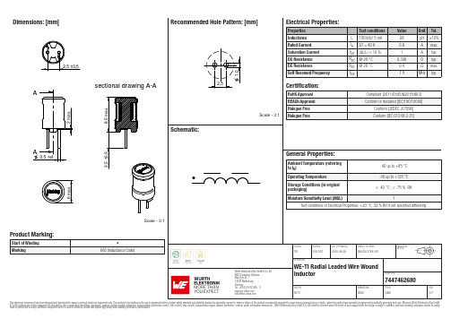
Dimensions: [mm]sectional drawing A-AScale - 3:17447462680744746268074474626807447462680T e m p e r a t u r eT T T 7447462680Cautions and Warnings:The following conditions apply to all goods within the product series of WE-TI of Würth Elektronik eiSos GmbH & Co. KG:General:•This electronic component was designed and manufactured for use in general electronic equipment.•Würth Elektronik must be asked for written approval (following the PPAP procedure) before incorporating the components into any equipment in fields such as military, aerospace, aviation, nuclear control, submarine, transportation (automotive control, train control, ship control), transportation signal, disaster prevention, medical, public information network, etc. where higher safety and reliability are especially required and/or if there is the possibility of direct damage or human injury.•Electronic components that will be used in safety-critical or high-reliability applications, should be pre-evaluated by the customer. •The component is designed and manufactured to be used within the datasheet specified values. If the usage and operation conditions specified in the datasheet are not met, the wire insulation may be damaged or dissolved.•Do not drop or impact the components, the component may be damaged.•Würth Elektronik products are qualified according to international standards, which are listed in each product reliability report. Würth Elektronik does not warrant any customer qualified product characteristics beyond Würth Elektroniks’ specifications, for its validity and sustainability over time.•The customer is responsible for the functionality of their own products. All technical specifications for standard products also apply to customer specific products.Product specific:Soldering:•The solder profile must comply with the technical product specifications. All other profiles will void the warranty.•All other soldering methods are at the customers’ own risk.Cleaning and Washing:•Washing agents used during the production to clean the customer application might damage or change the characteristics of the wire insulation, marking or plating. Washing agents may have a negative effect on the long-term functionality of the product. Potting:•If the product is potted in the costumer application, the potting material might shrink or expand during and after hardening. Shrinking could lead to an incomplete seal, allowing contaminants into the core. Expansion could damage the components. We recommend a manual inspection after potting to avoid these effects. Storage Conditions:• A storage of Würth Elektronik products for longer than 12 months is not recommended. Within other effects, the terminals may suffer degradation, resulting in bad solderability. Therefore, all products shall be used within the period of 12 months based on the day of shipment.•Do not expose the components to direct sunlight.•The storage conditions in the original packaging are defined according to DIN EN 61760-2.•The storage conditions stated in the original packaging apply to the storage time and not to the transportation time of the components. Packaging:•The packaging specifications apply only to purchase orders comprising whole packaging units. If the ordered quantity exceeds or is lower than the specified packaging unit, packaging in accordance with the packaging specifications cannot be ensured. Handling:•Violation of the technical product specifications such as exceeding the nominal rated current will void the warranty.•Applying currents with audio-frequency signals might result in audible noise due to the magnetostrictive material properties. •Due to heavy weight of the components, strong forces and high accelerations might have the effect to damage the electrical connection or to harm the circuit board and will void the warranty.•Please be aware that products provided in bulk packaging may get bent and might lead to derivations from the mechanical manufacturing tolerances mentioned in our datasheet, which is not considered to be a material defect.•The temperature rise of the component must be taken into consideration. The operating temperature is comprised of ambient temperature and temperature rise of the component.The operating temperature of the component shall not exceed the maximum temperature specified.These cautions and warnings comply with the state of the scientific and technical knowledge and are believed to be accurate and reliable.However, no responsibility is assumed for inaccuracies or incompleteness.Würth Elektronik eiSos GmbH & Co. KGEMC & Inductive SolutionsMax-Eyth-Str. 174638 WaldenburgGermanyCHECKED REVISION DATE (YYYY-MM-DD)GENERAL TOLERANCE PROJECTIONMETHODTRi002.0072020-06-25DIN ISO 2768-1mDESCRIPTIONWE-TI Radial Leaded Wire WoundInductor ORDER CODE7447462680SIZE/TYPE BUSINESS UNIT STATUS PAGEImportant NotesThe following conditions apply to all goods within the product range of Würth Elektronik eiSos GmbH & Co. KG:1. General Customer ResponsibilitySome goods within the product range of Würth Elektronik eiSos GmbH & Co. KG contain statements regarding general suitability for certain application areas. These statements about suitability are based on our knowledge and experience of typical requirements concerning the areas, serve as general guidance and cannot be estimated as binding statements about the suitability for a customer application. The responsibility for the applicability and use in a particular customer design is always solely within the authority of the customer. Due to this fact it is up to the customer to evaluate, where appropriate to investigate and decide whether the device with the specific product characteristics described in the product specification is valid and suitable for the respective customer application or not.2. Customer Responsibility related to Specific, in particular Safety-Relevant ApplicationsIt has to be clearly pointed out that the possibility of a malfunction of electronic components or failure before the end of the usual lifetime cannot be completely eliminated in the current state of the art, even if the products are operated within the range of the specifications.In certain customer applications requiring a very high level of safety and especially in customer applications in which the malfunction or failure of an electronic component could endanger human life or health it must be ensured by most advanced technological aid of suitable design of the customer application that no injury or damage is caused to third parties in the event of malfunction or failure of an electronic component. Therefore, customer is cautioned to verify that data sheets are current before placing orders. The current data sheets can be downloaded at .3. Best Care and AttentionAny product-specific notes, cautions and warnings must be strictly observed. Any disregard will result in the loss of warranty.4. Customer Support for Product SpecificationsSome products within the product range may contain substances which are subject to restrictions in certain jurisdictions in order to serve specific technical requirements. Necessary information is available on request. In this case the field sales engineer or the internal sales person in charge should be contacted who will be happy to support in this matter.5. Product R&DDue to constant product improvement product specifications may change from time to time. As a standard reporting procedure of the Product Change Notification (PCN) according to the JEDEC-Standard inform about minor and major changes. In case of further queries regarding the PCN, the field sales engineer or the internal sales person in charge should be contacted. The basic responsibility of the customer as per Section 1 and 2 remains unaffected.6. Product Life CycleDue to technical progress and economical evaluation we also reserve the right to discontinue production and delivery of products. As a standard reporting procedure of the Product Termination Notification (PTN) according to the JEDEC-Standard we will inform at an early stage about inevitable product discontinuance. According to this we cannot guarantee that all products within our product range will always be available. Therefore it needs to be verified with the field sales engineer or the internal sales person in charge about the current product availability expectancy before or when the product for application design-in disposal is considered. The approach named above does not apply in the case of individual agreements deviating from the foregoing for customer-specific products.7. Property RightsAll the rights for contractual products produced by Würth Elektronik eiSos GmbH & Co. KG on the basis of ideas, development contracts as well as models or templates that are subject to copyright, patent or commercial protection supplied to the customer will remain with Würth Elektronik eiSos GmbH & Co. KG. Würth Elektronik eiSos GmbH & Co. KG does not warrant or represent that any license, either expressed or implied, is granted under any patent right, copyright, mask work right, or other intellectual property right relating to any combination, application, or process in which Würth Elektronik eiSos GmbH & Co. KG components or services are used.8. General Terms and ConditionsUnless otherwise agreed in individual contracts, all orders are subject to the current version of the “General Terms and Conditions of Würth Elektronik eiSos Group”, last version available at .Würth Elektronik eiSos GmbH & Co. KGEMC & Inductive SolutionsMax-Eyth-Str. 174638 WaldenburgGermanyCHECKED REVISION DATE (YYYY-MM-DD)GENERAL TOLERANCE PROJECTIONMETHODTRi002.0072020-06-25DIN ISO 2768-1mDESCRIPTIONWE-TI Radial Leaded Wire WoundInductor ORDER CODE7447462680SIZE/TYPE BUSINESS UNIT STATUS PAGE。
MSM51V16805D-70JS中文资料
Output Low Voltage
VOL IOL = 2.0 mA
0 0.4 0 0.4 0 0.4 V
0 V £ VI £ VCC + 0.3 V;
Input Leakage Current ILI All other pins not –10 10 –10 10 –10 10 mA
under test = 0 V
Capacitance
Parameter Input Capacitance (A0 - A8, A9R - A11R)
Input Capacitance (RAS, CAS, WE, OE) Output Capacitance (DQ1 - DQ8)
Symbol
CIN1 CIN2 CI/O
Rating
DESCRIPTION
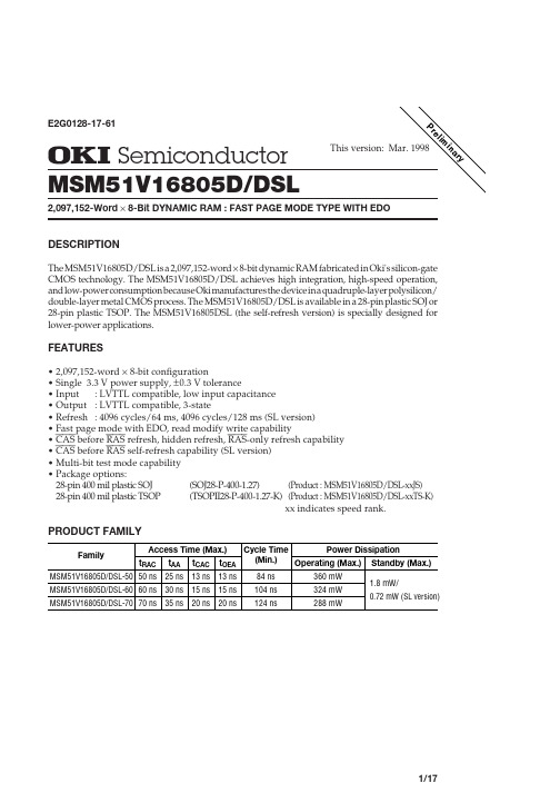
The MSM51V16805D/DSL is a 2,097,152-word ¥ 8-bit dynamic RAM fabricated in Oki's silicon-gate CMOS technology. The MSM51V16805D/DSL achieves high integration, high-speed operation, and low-power consumption because Oki manufactures the device in a quadruple-layer polysilicon/ double-layer metal CMOS process. The MSM51V16805D/DSL is available in a 28-pin plastic SOJ or 28-pin plastic TSOP. The MSM51V16805DSL (the self-refresh version) is specially designed for lower-power applications.
OPB680;OPB680-20;OPB690Z;OPB690;中文规格书,Datasheet资料
/
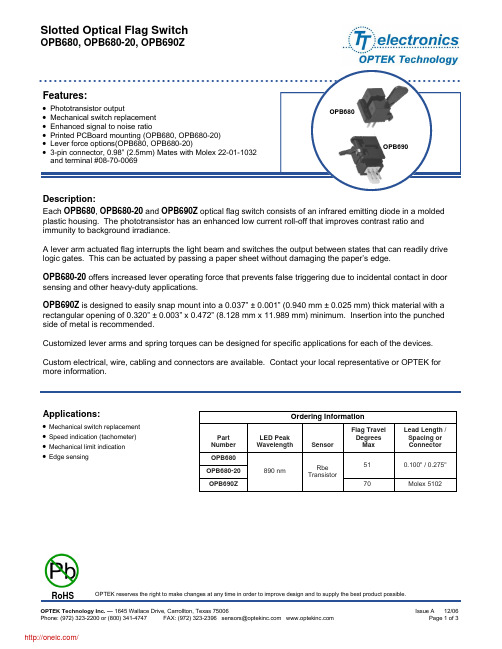
Slotted Optical Flag Switch
OPB680, OPB680-20, OPB690Z
Absolute Maximum Ratings (TA=25°C unless otherwise noted)
Storage & Operating Temperature Range Lead Soldering Temperature [1/16 inch (1.6 mm) from the case for 5 sec. with soldering iron] Input Diode Forward DC Current Peak Forward Current (1 µs pulse width, 300 pps) Reverse DC Voltage Power Dissipation
Output Phototransistor (See OP755 for additional information) V(BR)CEO BVECO ICEO Coupled VSAT IC(ON) Mechanical FOP Cycles Operating Force OPB680, OPB690Z OPB680-20 Operating Cycles 100 K 1.5 20 Saturation Voltage On-State Collector Current 150 600 0.4 µA IF = 10 mA, VCE = 5 V, blocked V IF = 10 mA, IC = 100 µA IF = 10 mA, VCE = 5 V, unblocked Collector-Emitter Breakdown Voltage Emitter-Collector Breakdown Voltage Collector-Emitter Dark Current 30 4.0 100 V V µA IC = 100 µA IEC = 100 µA VCE = 5 V
WM8805数据手册 中英文对照
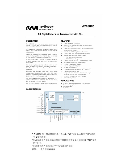
* WM8805是一种高性能的用户模式S / PDIF收发器,支持8个接收通道和1传输通道。
*用晶振或由外部提供高质量的主时钟用来恢复低抖动地由S / PDIF提供的主时钟。
*用高性能的内部锁相环产生所有典型的音频时钟。
一个专用的CLKOU脚提供了一个高驱动时钟输出。
*通过提供一个选项,允许设备仅仅是用来清理(de抖动)接收到的数字音频信号。
*该设备可用于在软件的控制模式或独立的硬件控制模式。
在软件控制方式,支持2-wire和3-wire接口模式。
*状态和错误监测是内置的,结果可以通过控制接口读出,在“标志”模式下通过音频数据接口GPO脚(音频数据和状态标志附加)。
*音频数据接口支持I2S,向左对齐,右对齐和DSP音频格式的字长16位,与采样率从32到192KHz/秒。
*设备提供一个28脚无铅SSOP封装。
1.数字输入插脚有施密特触发器的输入缓冲区。
2.参考表6设备配置在上电或硬件复位。
1.锁相环和数字供电必须始终在供电电压范围0.3 v以内内。
2.锁相环和数字地必须始终在地电压的0.3 v以内。
1. 锁相环和数字供电必须始终在供电电压范围0.3 v以内内。
2. 锁相环和数字地必须始终在地电压的0.3 v以内。
DEVICE DESCRIPTION设备描述INTRODUCTION FEATURES介绍功能•IEC-60958-3 compatible with 32 to 192k frames/s support.IEC - 60958 - 3兼容32到192 k帧/ s的支持•Supports AES-3 data frames.支持aes 3数据帧•Support for reception and transmission of S/PDIF data.支持S / PDIF数据的接收和传输。
•Clock synthesis PLL with reference clock input and low jitter output.时钟合成锁相环根据参考时钟输入并输出低抖晃的信号。
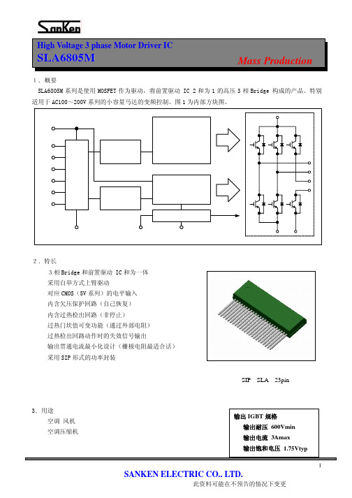
SLA6805M应用手册
(9)FO 端子 异常时的信号输出端子。内部回路请参考右图。 检验出过热时输出(5V)信号。欠压保护电路 动作时是不输出信号。
端子内部等价回路
5
SANKEN ELECTRIC CO., LTD.
此资料可能在不预告的情况下变更
High Voltage 3 phase Motor Driver IC
SLA6805M
2
SANKEN ELECTRIC CO., LTD.
此资料可能在不预告的情况下变更
High Voltage 3 phase Motor Driver IC
SLA680n
自举电容的最佳值是通过驱动方式 (调制方法及输出频率) ; 开关频率 (载波频率) ; 载空率 (Duty) ; 驱动IGBT的门坎输入容量变化。 三相PWM调制方式,120度度通电方式时的选定例为以下。 SLA6805M的情况 条件:自举电流限制电阻=3.3Ω
5.有关保护功能 SLA6805M 的时序表。
Mass Production
6
SANKEN ELECTRIC CO., LTD.
此资料可能在不预告的情况下变更
High Voltage 3 phase Motor Driver IC
SLA6805M
(1)控制电源欠压保护(UVLO)
Mass Production
3
SANKEN ELECTRIC CO., LTD.
此资料可能在不预告的情况下变更
High Voltage 3 phase Motor Driver IC
SLA6805M
(3)VCC1、VCC2 端子
Mass Production
内含前置 IC 的控制电源的端子。请在 VCC1、VCC2 的外部基板上进行连接。为了防止电源浪涌等造成的 误动作, 请在端子附近安装电解电容。 另外, 干扰较多的情况, 请去除和电解电容并连的陶瓷电容。 VCC1 和 VCC2 端子内含欠压保护回路。VCC2 端子电压的保护电压以外的范围进行使用。 (4)COM1、COM2 端子 内含控制前置 IC 的 GND 端子。请在 COM1、COM2 的外部基板上连接。由于此端子的电位的变动会造成误 动作,请充分考虑布线(在没有 Power 电流变动的地方连接,布线长度的缩短等) 。
AU简明操作手册簿(480-680)

简明操作手册(AU全自动生化仪培训资料Ver 1.0)适用机型:贝克曼AU480贝克曼AU680每天工作流程:一、开机前检查;二、开机;三、修改日期索引;四、检查、添加试剂;五、做质控,查看质控结果;六、如有必要,做定标;七、做定标项目的质控,查看结果;八、做标本;九、插入急诊标本;十、查看标本结果;十一、传输标本结果;十二、关机;十三、常见符号;十四、常见报警。
主要按键介绍一、开机前检查1、检查样品配送器、试剂配送器是否泄漏;2、检查清洁剂蠕动泵装置是否泄漏;3、检查主清洁剂的数量并补给;4、检查并清洗样品探针、试剂探针和搅拌棒;二、开机开启ON键,仪器主机以及操作电脑将会自动启动,操作电脑进入“修改日期索引”界面。
三、修改日期索引1、开机后,仪器自动进入以下界面2、点击OK,仪器将自动建立一个日期索引。
注:每天必须修改日期索引,并且每天只能修改一次,如果当天第二次开机,则选择“Current Index”,然后点击OK,仪器将不建立新索引。
四、检查、添加试剂1、点击“主菜单”2、点击“Roution”3、点击“Reagent”点击“Reagent”后,进入以下界面点击“Details”点击“Details”后,进入以下界面点击“Reagent Check”,进入以下界面1、在此查看各试剂剩余测试数,如果哪个试剂少,请添加。
2、点击“Reagent Check”。
1、如果添加的试剂品种很多,就使用第一个选择;2、如果添加试剂品种只有几个,使用第二个;3、第三个选择几乎不用;4、试剂状态显示红色的时候,使用“试剂复位”。
选择好后,点击“Start”,仪器将对试剂进行检查。
五、做质控,查看质控结果1、做质控:将质控品放在“绿色”样品架相应的位置,将“绿色”样品架放置于仪器进样轨道上,点仪器“开始”键。
仪器自动做设置好的项目的质控。
2、查看质控结果:在中文报告系统,点击“质控”“质控图”,即可查看质控结果。
AU680简易操作规程纯中文版

AU680简易操作规程版本:1.01、 开机:如果是正常开机,则只需按仪器上的ON键。
如果是异常关机(如紧急停机),则先按仪器上的RESET,再按ON键。
每次开机时都会提问是否建立一个新的Index,一般选择Yes。
2、 关机:选择键盘END——选择是即可。
仪器及电脑自动关闭,不需要按任何按钮。
3、 试剂检查a) 原装有条码试剂。
点击“主页面”——选择“试剂管理”——进入“试剂管理 ”选择“主”——点击“试剂检查”——点击“详细信息”进入“详细信息”界面观察试剂详细信息 。
b) 非原装无条码试剂。
点击“主页面”——选择“试剂管理”——点击“详细信息”——在“试剂显示”处选“位置”——上下翻页——选择需要放置试剂的位置——点击“位置设置”——选择为“固定试剂”——点击“编辑”编辑相应的试剂名称和相关信息。
——点击“确认”保存并退出。
4、 定标点击“主页面”——选择“样本架申请”——点击“定标”——点击“开始登陆”——选需定标项目及定标模式(RB或CAL)如果选了CAL则RB也一定会被选上——点击“确认”保存并退出。
电解质定标:点击“主页面”——选择“分析仪保养”——选择“ISE保养”——点击“定标”——点击“血清检测启动”,将相应定标液放置在相应位置,点击“开始”5、 样本编程a) 单个样本编程:点击“主页面”——选择“样本架申请”——选择“样品”中的“测试申请”——在“样品号”中确认当前需编辑的样本号 ——确认后点击“开始登陆”后选择项目——点击“登陆”确认——如要编辑下一样本,继续选择项目,然后点击“登陆”——完成项目编程后点击“退出” ——将相应的样本按顺序放在白架子上放在进样区——点击“开始”开始运行。
b) 批量样本编程:点击“主页面”——选择“样品架申请”——选择“样品”中的“测试请求”——在“样品号”中确认当前需编辑的样本号 ——确认后点击“开始登陆”后选择项目——点击“批输入” ——选择“样品数”中输入需批量编程的样本数——点击“OK”后再次确认“样品号”处——确认后点击“退出” ——将相应的样本按顺序放在白架子上放在进样区——点击“开始”开始运行。
TDK EPC 680型号电容器说明书
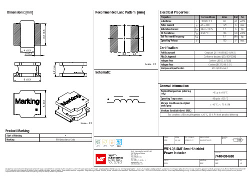
Dimensions: [mm]Scale - 4:174404084680BC74404084680T e m p e r a t u r eT pT L74404084680Cautions and Warnings:The following conditions apply to all goods within the product series of WE-LQS of Würth Elektronik eiSos GmbH & Co. KG:General:•This electronic component is designed and manufactured for use in general electronic equipment.•Würth Elektronik must be asked for written approval (following the PPAP procedure) before incorporating the components into any equipment in fields such as military, aerospace, aviation, nuclear control, submarine, transportation (automotive control, train control, ship control), transportation signal, disaster prevention, medical, public information network etc. where higher safety and reliability are especially required and/or if there is the possibility of direct damage or human injury.•Electronic components that will be used in safety-critical or high-reliability applications, should be pre-evaluated by the customer. •The component is designed and manufactured to be used within the datasheet specified values. If the usage and operation conditions specified in the datasheet are not met, the wire insulation may be damaged or dissolved.•Do not drop or impact the components, the component may be damaged.•Würth Elektronik products are qualified according to international standards, which are listed in each product reliability report. Würth Elektronik does not warrant any customer qualified product characteristics beyond Würth Elektroniks’ specifications, for its validity and sustainability over time.•The responsibility for the applicability of the customer specific products and use in a particular customer design is always within the authority of the customer. All technical specifications for standard products also apply to customer specific products.Product specific:Soldering:•The solder profile must comply with the technical product specifications. All other profiles will void the warranty.•All other soldering methods are at the customers’ own risk.•Strong forces which may affect the coplanarity of the components’ electrical connection with the PCB (i.e. pins), can damage the part, resulting in avoid of the warranty.Cleaning and Washing:•Washing agents used during the production to clean the customer application might damage or change the characteristics of the wire insulation, marking or plating. Washing agents may have a negative effect on the long-term functionality of the product.•Using a brush during the cleaning process may break the wire due to its small diameter. Therefore, we do not recommend using a brush during the PCB cleaning process.Potting:•If the product is potted in the customer application, the potting material may shrink or expand during and after hardening. Shrinking could lead to an incomplete seal, allowing contaminants into the core. Expansion could damage the components. We recommend a manual inspection after potting to avoid these effects.Storage Conditions:• A storage of Würth Elektronik products for longer than 12 months is not recommended. Within other effects, the terminals may suffer degradation, resulting in bad solderability. Therefore, all products shall be used within the period of 12 months based on the day of shipment.•Do not expose the components to direct sunlight.•The storage conditions in the original packaging are defined according to DIN EN 61760-2.•The storage conditions stated in the original packaging apply to the storage time and not to the transportation time of the components. Packaging:•The packaging specifications apply only to purchase orders comprising whole packaging units. If the ordered quantity exceeds or is lower than the specified packaging unit, packaging in accordance with the packaging specifications cannot be ensured. Handling:•Violation of the technical product specifications such as exceeding the nominal rated current will void the warranty.•Applying currents with audio-frequency signals may result in audible noise due to the magnetostrictive material properties.•The temperature rise of the component must be taken into consideration. The operating temperature is comprised of ambient temperature and temperature rise of the component.The operating temperature of the component shall not exceed the maximum temperature specified.These cautions and warnings comply with the state of the scientific and technical knowledge and are believed to be accurate and reliable.However, no responsibility is assumed for inaccuracies or incompleteness.Würth Elektronik eiSos GmbH & Co. KGEMC & Inductive SolutionsMax-Eyth-Str. 174638 WaldenburgGermanyCHECKED REVISION DATE (YYYY-MM-DD)GENERAL TOLERANCE PROJECTIONMETHODChrB002.0002023-03-27DIN ISO 2768-1mDESCRIPTIONWE-LQS SMT Semi-ShieldedPower Inductor ORDER CODE74404084680SIZE/TYPE BUSINESS UNIT STATUS PAGEImportant NotesThe following conditions apply to all goods within the product range of Würth Elektronik eiSos GmbH & Co. KG:1. General Customer ResponsibilitySome goods within the product range of Würth Elektronik eiSos GmbH & Co. KG contain statements regarding general suitability for certain application areas. These statements about suitability are based on our knowledge and experience of typical requirements concerning the areas, serve as general guidance and cannot be estimated as binding statements about the suitability for a customer application. The responsibility for the applicability and use in a particular customer design is always solely within the authority of the customer. Due to this fact it is up to the customer to evaluate, where appropriate to investigate and decide whether the device with the specific product characteristics described in the product specification is valid and suitable for the respective customer application or not.2. Customer Responsibility related to Specific, in particular Safety-Relevant ApplicationsIt has to be clearly pointed out that the possibility of a malfunction of electronic components or failure before the end of the usual lifetime cannot be completely eliminated in the current state of the art, even if the products are operated within the range of the specifications.In certain customer applications requiring a very high level of safety and especially in customer applications in which the malfunction or failure of an electronic component could endanger human life or health it must be ensured by most advanced technological aid of suitable design of the customer application that no injury or damage is caused to third parties in the event of malfunction or failure of an electronic component. Therefore, customer is cautioned to verify that data sheets are current before placing orders. The current data sheets can be downloaded at .3. Best Care and AttentionAny product-specific notes, cautions and warnings must be strictly observed. Any disregard will result in the loss of warranty.4. Customer Support for Product SpecificationsSome products within the product range may contain substances which are subject to restrictions in certain jurisdictions in order to serve specific technical requirements. Necessary information is available on request. In this case the field sales engineer or the internal sales person in charge should be contacted who will be happy to support in this matter.5. Product R&DDue to constant product improvement product specifications may change from time to time. As a standard reporting procedure of the Product Change Notification (PCN) according to the JEDEC-Standard inform about minor and major changes. In case of further queries regarding the PCN, the field sales engineer or the internal sales person in charge should be contacted. The basic responsibility of the customer as per Section 1 and 2 remains unaffected.6. Product Life CycleDue to technical progress and economical evaluation we also reserve the right to discontinue production and delivery of products. As a standard reporting procedure of the Product Termination Notification (PTN) according to the JEDEC-Standard we will inform at an early stage about inevitable product discontinuance. According to this we cannot guarantee that all products within our product range will always be available. Therefore it needs to be verified with the field sales engineer or the internal sales person in charge about the current product availability expectancy before or when the product for application design-in disposal is considered. The approach named above does not apply in the case of individual agreements deviating from the foregoing for customer-specific products.7. Property RightsAll the rights for contractual products produced by Würth Elektronik eiSos GmbH & Co. KG on the basis of ideas, development contracts as well as models or templates that are subject to copyright, patent or commercial protection supplied to the customer will remain with Würth Elektronik eiSos GmbH & Co. KG. Würth Elektronik eiSos GmbH & Co. KG does not warrant or represent that any license, either expressed or implied, is granted under any patent right, copyright, mask work right, or other intellectual property right relating to any combination, application, or process in which Würth Elektronik eiSos GmbH & Co. KG components or services are used.8. General Terms and ConditionsUnless otherwise agreed in individual contracts, all orders are subject to the current version of the “General Terms and Conditions of Würth Elektronik eiSos Group”, last version available at .Würth Elektronik eiSos GmbH & Co. KGEMC & Inductive SolutionsMax-Eyth-Str. 174638 WaldenburgGermanyCHECKED REVISION DATE (YYYY-MM-DD)GENERAL TOLERANCE PROJECTIONMETHODChrB002.0002023-03-27DIN ISO 2768-1mDESCRIPTIONWE-LQS SMT Semi-ShieldedPower Inductor ORDER CODE74404084680SIZE/TYPE BUSINESS UNIT STATUS PAGE。
CD680 CD685手机快速启动指南说明书

CD680/CD685Note * In multi-handset packs, there are additional handsets, chargers and power adapters.** In some countries, you have to connect the line adapter to the line cord, then plug the line cord to the telephone socket.Caution • Use only the supplied batteries and power adapter.What’s in the box***Line cord**User manual Quick start guide Guarantee1Connect2Get started3EnjoyCall• T o make a call,press and dial the phone number.• T o answer a call,press when the phone rings.• T o end a call,press .Adjust the earpiece volumePress or to adjust the volume during a call. Add a contact in the phonebook1 Press .2 Select [Option] > [Add new],then press [OK] to confirm.3 Enter the name then press [OK] to confirm.4 Enter the number,then press [Save] to confirm.Record an announcement(for CD685 only)1 Press [Menu]2 Select > [Announcement],then press [OK] to confirm.3 Select [Answer only] or [Answer & rec.],then press [OK] to confirm.4 Select [Record new],then press [OK] to confirm.5 Start recording close to the microphone after the beep.6 Press [OK] to stop recording.»Y ou can listen to the newly recordedannouncement on the handset.Need help?User manualRefer to the user manual that came with your new phone.Online help /supportWelcome to PhilipsRegister your product at /welcome Reproduction in whole or in part is prohibited without the written consent of the copyright owner.Trademarks are the property of Koninklijke Philips Electronics N.V. or their respective owners.© 2011 Koninklijke Philips Electronics N.V. All rights reserved.QSG_CD680-685_EN_V2.1WK11245。
英文易维达阻旋式料位计说明书
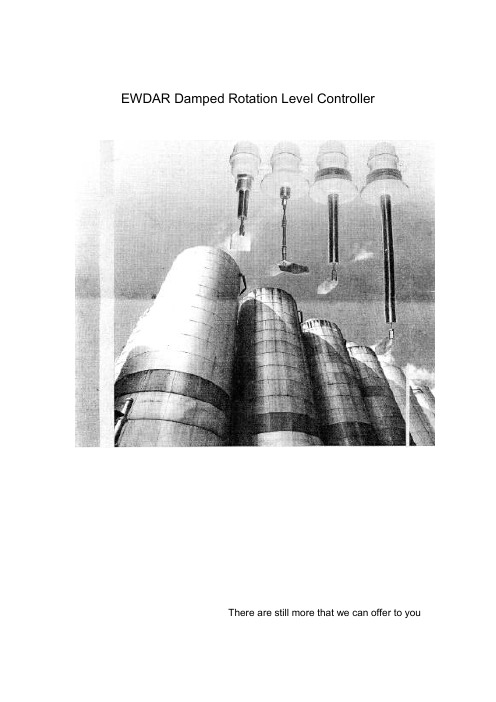
EWDAR Damped Rotation Level ControllerThere are still more that we can offer to youSincere services to clients:With the increasing competition in the market, instruments that are accurate in measuring and free of maintenance can help to improve the production efficiency of the factories. EWDAR level control system is such a product that can substantially improve the product quality and work efficiency of your company. We are always available to supply standard products or provide tailor-made products in response to your requirement for various application of EWDAR level measuring products in such industries as power, cement, engineering machinery, casting, chemical and food processing etc. In addition to the excellent measuring technology, EWDAR will always provide high-quality services to all clients.1、Applications and characteristics:EWDAR series damped rotation level control system has wide applications in the modern industry production process and warehousing sector for level monitoring or control of the powder and grain substances in the open type vessels. With full new design concept introduced in the product and many years of successful experiences, EWDAR series damped rotation level control system features extreme low failure and unanimous positive comments from the clients of all walks of life. EWDAR series damped rotation type level control system features advanced technology, reasonable structure, reliable performance, easy and convenient use and maintenance as well as high cost performance etc; Compared with similar products in the market, EWDAR level control system has the following unique characteristics:1) All major exposed parts and components use such materials as stainless steel,aluminum alloy or high-grade engineering plastic featuring such outstanding advantages as dust-proof, moisture resistance, corrosion resistance and no pollution to environment. EWDAR may be used in severe working environment in such industries as power, cement, casting, concrete, asphalt mixing equipments, food processing, grain warehousing and industries with high produce of dust etc;2) The output shaft is equipped with overload protection device, which caneffectively avoid damages to the motors and speed reducers due to improper use or abnormal external force;3) In order to make the equipment suitable for different materials with differentspecific gravity and also for purpose of easy installation and adjusting, the equipment is provided sensitive five-gear adjusting device and two installation options as well as many monitoring vane specifications;4) ZXKHB type level control system is equipped with overheat protection device,which can ensure proper and normal working of the level control at temperature of 300℃and below. (This ability is out of reach of some capacitor type, pitchfork type and ultrasonic type level monitors);2、Working principle:The working principle of EWDAR series damped rotation type level controller isdescribed as following: Use of AC micro motor with speed reduction to drive the monitoring vane rotate at slow speed; when the level of the materials rises till the rotation of the vanes is blocked, the testing mechanism will have rotation displacement around the main shaft; this displacement will first put one micro switch in action to send signal that material is fed inside; and then the other micro switch will act to disconnect the power supply to the micro motor to stop the motor; as long as the level in the silo or container remains unchanged, this work status will be always maintained;When the material level decreases till the vanes are tested with no blockage, the testing mechanism will restore to the original state due to pull force of the spring. First one micro switch will act to switch on the power supply to the motor to make the motor run, then the other micro switch will act will send signal that material is in shortage; as long as the rotation of the vanes will not be blocked by the materials, this work status will be always maintained.3、Outline dimensions:1) Outline dimensions ( Figure 1)2) Outline dimensions (Figure 2):4、Main technical specification:5、Type selection of damped rotation type level control system:Thread connectionFlange connectionLength6、Installation guideline:Unit: mmSilo wallTailor-made dimension may be available upon client’s request!。
瑞塔尔钢制壁挂电缆盒和壁挂电盒规格指南说明书

Junction Box and Wallmount Enclosure Specification GuideA good thing just got better.wallmount enclosures offer Rittal WM and JB EnclosuresF eatures a stylish, modern design that safely houses more components in a smaller space M ulti-fold single piece body construction for outstanding strength and stability with fewer weldsP owder coated with RAL 7035 light grey over an industry exclusive electrophoretic dip-coat powder paint primer for complete coverage and protection of the enclosure surfaceF lange collar enclosure opening and seamless foamed-in-place gasketing create a knife edge seal for tight, secure protection against contaminates and dustM ost include zinc plated, depth adjustable mounting panel (up to 10% larger than equivalent sized NEMA enclosures) with increased surface area for mounting equipmentRittal stocks thousands of enclosures in three US warehouses for next day shipmentJB & WM Specification GuideZinc galvanized mounting panel included. Panel depth adjustable mounting provisions.Foam in place gasketing assures a continuous seal.Easy to access wallmounting holes even with panel installed.1/4-turn latch for ease of access/closure/security.Fully welded construction, powder coated RAL7035 Light Gray.Ground provisions.Removable hinge pins allow easy door removal for modification. Opposite side has pre-drilled holes for convenient door reversal.Knife edge flange trough collar diverts liquids, dirt and dust.Door bars forwire management and component mounting.RITT AL SHIPS QUICK!Made in the USAGet the FREE Wallmount App for iOS and AndroidRittal Wallmounts. A good thing just got better.Y ou’ve known Rittal quality in Wallmount Enclosures for years. Now you can get the industry’s highest-quality enclosures in over 100 standard sizes, available in both carbon and stainless steel. And, with our American manufacturing plant located in central Ohio, you won’t have to wait for the perfect Rittal enclo-sure you need for your facility today.4Note: inch measurements are roundedJB & WM Specification GuideConfiguration:One-piece welded cold-rolled steel bodyLeft-hand hinged door (the carbon steel single door configuration is reversible)Single door enclosures less than 20” in height have one 1/4 turn latch with screwdriver insertSingle door enclosures 20 - 40” in height have two 1/4-turn latches with screwdriver insertsSingle door enclosures greater than or equal to 42” in height have a 3-point latching tool-to-open L-handleDouble door and disconnect enclosures have a 3-point latching tool-to-open L-handleWallmounting holes (carbon steel versions); blind riv-nuts (stainless steel versions)Foamed-in-place gasketSlope Top enclosures have a 20° sloped roof that overhangs the doorZinc-plated mounting panel includedMaterial:Housing and door (carbon steel): Dip-coat primed, powder-coated RAL 7035 light gray- 12”H x 12”W - 24”H x 20”W, 16 ga (1.5 mm) body and door- 24”H x 24”W - 36”H x 24”W, 16 ga (1.5 mm) body and 14 ga (2.0 mm) door- 36”H x 30”W - 60”H x 36”W, 14 ga (2.0 mm) body and doorHousing and door (stainless steel): Stainless Steel, #4 Brushed FinishProtection Ratings:-Single door, disconnect and slope top enclosures UL/cUL Type 1, 3R, 12, 4 (4X stainless steel)-Double door enclosures UL/cUL Type 1, 12UL File Number E170282WM Wallmount EnclosuresProduct TypeHeightWidthDepthDisconnect N = Non-disconnect X = DisconnectMaterialC = Carbon Steel 4 = Stainless Steel 3046 = Stainless Steel 316LSlope Top VersionWM S 12 12 06 N CUnderstanding the Part Number:WM Wallmount Enclosures5Note: inch measurements are roundedJB & WM Specification GuideWM Wallmount Enclosures*Additional latching option available. In addition to the standard ¼-turn latching system, a 3-point latch option is available for these products.To order add “3PT” at the end of marked alphanumeric part number. Ex: WM242008N43PT.6Note: inch measurements are rounded JB & WM Specification GuideWM Wallmount Enclosures*Additional latching option available. In addition to the standard ¼-turn latching system, a 3-point latch option is available for these products.To order add “3PT” at the end of marked alphanumeric part number. Ex: WM242008N63PT.7 JB & WM Specification GuideNote: inch measurements are rounded8Note: inch measurements are roundedJB & WM Specification GuideWM Wallmount EnclosuresWM Wallmount Enclosures—Type 316L Stainless Steel (mounting panel included)*Additional latching option available. In addition to the standard ¼-turn latching system, a 3-point latch option is available for these products. To order add “3PT” at the end of marked alphanumeric part number. Ex: WM242008N63PT.9Note: inch measurements are roundedJB & WM Specification Guide WM Wallmount Enclosures316 Stainless Steel Wallmount EnclosuresRITT AL SHIPS QUICK!Made in the USAGet the FREE Wallmount App for iOS and AndroidFoam in placegasketing provide a water and dust proof environmental seal.Fully welded construction, 316 Stainless SteelRemovable 316 stainless steel hinge pins allow easy door removal for modification.Ground provisions.Defined edge flange trough collar diverts liquids, dirt and dust.Stainless steel 316 screwdriver insert and Rear, blind nut design enables enclosure to be10Note: inch measurements are rounded JB & WM Specification GuideConfiguration:One-piece welded cold-rolled steel body Left-hand hinged doorSingle quarter-turn latch with screwdriver insert Foamed-in-place gasketWallmounting holes (carbon steel versions) and blind riv-nuts (stainless steel versions)Note: Zinc-plated mounting panel included.Material:Housing and door (carbon steel): Dip-coat primed, powder-coated RAL 7035 light gray, 16 ga (1.5 mm)Housing and door (stainless steel):Stainless Steel, 16 ga (1.5 mm), #4 Brushed FinishProtection Ratings:UL/cUL Type 1, 3R, 12, 4 (4X stainless steel)UL File Number E170282Understanding the Part Number:JB 12 12 06 H CProduct TypeHeight Width DepthCover Type H = Hinged4 = Stainless Steel 3046 = Stainless Steel 316JB Junction Box Enclosures*Without Mounting PanelJB Junction Box Enclosures*Without Mounting Panel11 JB & WM Specification GuideNote: inch measurements are roundedJB & WM Accessories12Note: inch measurements are rounded JB & WM Specification GuideJB & WM Accessories13 JB & WM Specification GuideNote: inch measurements are roundedJB & WM Accessories14Note: inch measurements are roundedJB & WM Specification Guide15Note: inch measurements are roundedJB & WM Specification Guide Rittal Corporation is fully committed to ongoing product improvements. We will not be held responsible for any subsequent change in product specifications, performance claims or other data as well as any unintentional typographical errors contained herein.JB & WM AccessoriesReplacement parts can be found online at /spare-parts/0618 176Email:****************•Online:E-Mail:*******************•Online:www.rittal.caE-Mail:***************.mx•Website:.mx。
5.6inch并口模块规格书
Confidential5.6INCH 并口模块规格书型 号CD-056RADS-VQ1A首次发行日期 2014-09-01■ 暂订版规格书 □ 正式版规格书客户承认客户名称 承认人员 承认日期核准确认 版本Updated备注01 2014-09-01All right strictly reserved, The information contained herein shall not be distributed, reproduced, or disclosed in whole or in part without prior written permission of Chun Fung Technology (H.K) CO. LTD, Page 1Confidential改版记录版本 更新日期 页数 改版内容All right strictly reserved, The information contained herein shall not be distributed, reproduced, or disclosed in whole or in part without prior written permission of Chun Fung Technology (H.K) CO. LTD, Page 2Confidential内容&目录封面 ………………………………………………………………………………………… 01 改版记录…………………………………………………………………………………………02 目录 ………………………………………………………………………………………… 03 1 产品描述………………………………………………………………………………………… 04 2 产品编码规则………………………………………………………………………………… 04 3 产品讯息………………………………………………………………………………………… 04 3.1 基本特性……………………………………………………………………………… 04 3.2 触屏性能…………………………………………………………………………… 06 3.3 电性能 ……………………………………………………………………………… 06 3.4 可靠性参数………………………………………………………………… 06 3.5 接口参数 ……………………………………………………………… 06 3.6 外观缺陷 ……………………………………………………………… 08 4 产品结构图…………………………………………………………………………………… 9 5 注意事项……………………………………………………………………………………… 10 6 软件样本……………………………………………………………………………………… 10 7 联络讯息 ……………………………………………………………………………………… 31All right strictly reserved, The information contained herein shall not be distributed, reproduced, or disclosed in whole or in part without prior written permission of Chun Fung Technology (H.K) CO. LTD, Page 3Confidential1. 产品描述CD-056RADS-VQ1A 是一款高性能的 高性能的 TFT 驱动模块,支持 80xx/68xx 单芯片的 8 bit 并 口驱动。
Nichipet EX II MULTI 使用说明书
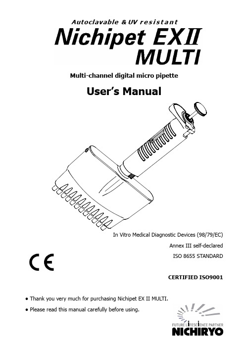
Multi-channel digital micro pipetteUser’s ManualAnnex III self-declaredISO 8655 STANDARDCERTIFIED ISO9001 ● Thank you very much for purchasing Nichipet EX II MULTI.● Please read this manual carefully before using.Multi-channel digital micro pipetteFeatures● Nichipet EX II MULTI is fully autoclavable at the condition of 121°C for 20 minutes.● Nichipet EX II MULTI is made of UV resistant material which can be used in clean bench. (If UV is applied to Nichipet EX II MULTI for a considerably long time, it may become discolored but nothing affects its performance.)●New round shape improves friendly handling capability, and mitigates operator’s fatigue from long time use.● Sample volume can easily be set by simply rotating the push button.● Setting of sample volume can easily be locked with one touch (one-touch lock mechanism).● Covering a wide range of 0.5μL to 300μL with 4 models each of 8 and 12 channels.●Patented body construction avoids permeating hand temperature through the body that prevents inaccuracy of volume measurement.● Suitable for sampling to a micro plate with 96 well and 9 mm pitch.● Because the handle and casing angle can be adjusted freely (360 degrees), the unit can be used at a position of your choice.● Includes tip eject function. The tips can be removed without touching them by fingers.● The simple casing structure enables easy maintenance.Standard accessories●Tip 8 ch .......................... x 1612 ch ......................... x 24●Grease ............................. x 1●Cleaning wire .................... x 1●User’s manual .................. x 1When unpacking package, check to make sure that the above-mentioned items are included. Precautions on safety● For using your Nichipet EX II MULTI properly and safely, carefully read “Precautions on safety” in this paragraph and “CAUTION” on the next page before starting work with it.● C ontents of “CAUTION” are matters that require user’s attention, not only for using Nichipet EX II MULTI properly but for preventing user from accidents and physical damage.●After reading this manual, please keep it in a convenient place for referring to at any time.Please read following prior to use for your safety and correct usage.CAUTIONNichipet EX II MULTI properly and safely.If the user misuses the Nichipet EX II MULTI, or disregards the following instructions, it may result in injury to the user or/and other persons or physical damage to this instrument or/and other equipment.1. Do not use for any other purpose than handling of liquid.2. Never modify this instrument, as this may cause an accident.3. Do not use for handling of liquids that will be directly injected into the body.4. As certain types of liquids are harmful to the body, never discharge any sample liquid whilepointing the instrument at a person5. Do not eject tips while this unit is pointed at a person.6. Do not eject tips when there is liquid inside.7. The sharp protruding tips of the unit are dangerous. Please use care when handling.8. Please make sure that the tips are securely attached to the nozzle. Scattering of liquid willoccur if tips fall off the nozzle.9. If liquid that is harmful to the body has splashed onto the unit, treat it properly beforeusing it.10. When using liquid that is harmful to the body, never touch a tip that has been used.11. Do not use this unit to mix liquid etc. This will cause tips to loosen, fall off, or result inliquid splashing on the unit.12. After autoclaving or drying, do not touch the unit as it is very hot. Touching the unit couldresult in bodily harm.13. Although this product is designed to resist chemicals, it may be damaged by some kindsof chemicals such as N-methyl-pyrrolidinone, etc. Please contact the manufacturer before using special chemicals.NoteUsers are required to strictly observethe following points in order forthe instrument to keep its excellent precision,reproducibility and original performance for a long time.1. Do not expose pipette directly to the sun when working with it or for 2 hours before starting work, otherwise the pipette may lose accuracy. Avoid working with pipettes in a humid and hot place.2. Just before starting work with pipette, avoid touching tip and nozzle cylinder as far as conditions are allowed. If nozzle cylinder is warmed by your hand, accuracy may vary.3. For pipetting, follow the forward method (the way explained in this manual). If it is performed in a different way, it may result in inaccurate pipetting.4. Operate push button very gently. If it is quickly released, it may result not only inaccurate pipetting but also deteriorated the pipette because sample liquid may be permeated into the main body.5. Do not reuse tip that has been used once, and carefully dispose used tip. If tip is used repeatedly, it may cause inaccurate and impure pipetting and cross contamination (*) among samples.*. For example, if previous sample liquid is left inside tip, it is mixed with new sample liquid and the new sample is contaminated by the previous one. Therefore, pipetting of the next sample results wrong. This phenomenon is called mutual contamination of samples.6. Do not hold pipette horizontally or upside down when there is liquid inside tip, otherwise the liquid gets into the main body and the pipette may be contaminated.7. When autoclaving, do not pile pipettes on others in the autoclave or lean pipettes with a nozzle top facing down so that self-load is applied on the nozzle. This pipette is made of an autoclave compatible material, but because of high temperature in the sterilizer, there is a risk that parts subject to load will be deformed.8. After autoclaving and drying pipette, leave it until it gets completely cool before using again. If the pipette is used when warm, the accuracy may not come up to the standard level.9. After autoclaving and drying pipette, assemble the pipette after it is completely cooled, if it is assembled when it is still hot, it may cause deterioration in the pipette such as breakage of the screw threads.10. When rotating push button, do not exceed the specified sample volume limit, otherwise pipette may be damaged or deteriorated.11. Do not perform pipetting with less liquid than set volume. If the quantity of liquid is less than the set volume, it may cause the liquid to scatter into the main body and the pipette may deteriorate in quality.ContentsOperating procedure (5)Disassembling/Reassembling the airtight chamber (9)Autoclaving/Drying the pipette (13)Specifications (14)Volume setting procedure (15)Troubleshooting (17)Parts list (18)Operating procedure1.Volume setting1) Turn the lock lever to unlocking direction to loosen it (Fig. A)2) Turn the push button to set the digital counter to a desired liquid volume. To increasevolume setting, turn the push button until passing designated volume setting by half of the scale, and then set the designated volume. To decrease volume setting, simply turn to designated volume. When setting the liquid volume, set the counter’s graduation at point mark (red) appearing in the lower part of counter window. (Fig. B)3) After setting the liquid volume, turn the lock handle to locking direction to lock it. (Fig. A) Note: Don’t exceed the specified liquid volume limit, otherwise pipette may be damaged or deteriorated in the quality.Note: After changing the volume, press and release push button for a several times before using.DecreaseIncreasePush buttonLock leverEjector buttonFig. AFig. BPoint mark Volume indicator1) Attach a new tip to the nozzle end. (We recommend that you attach it from rack)Note: It would be recommended that tips are directly picked up from rack. And do not twist pipette when fixing tip.2) Press down push button to first stop position “b”. (Fig. C)* Don’t aspirate the liquid with the push button pressed at the second stop “c”.3) Hold the pipette vertically and immerse the tip 2mm to 3mm below the surface of the liquid.(Fig. D-①)4) Release the push button slowly and smoothly to aspirate the set volume of the liquid.(Fig. D-②)5) Wait 1 to 2 seconds, then withdraw the pipette vertically and carefully from the surface ofthe liquid. (Fig. D-②)6) Wipe any droplets away from the outside of the tip using a medical wipe and avoidtouching the tip’s orifice.Note: Do not aspirate when push button position is at “c”.Note: The push button has to be pushed and released slowly. Otherwise it may cause wrong accuracy.abc Ejector button1) Gently place the end of tip against inside wall of recipient vessel just above liquid surface 10 degrees to 45 degrees in angle.2) Press down the push button slowly and smoothly to the first stop “b”. Wait for a few seconds then press down the push button to the second stop to expel the last drop of the liquid from the tip. (Fig. D-④,⑤) 3) Release the push button slowly.⑥)When using any toxic or harmful liquid to human, do not touch any used tips.Fig. Db ca① ② ③ ④ ⑤ ⑥Ejector button 4. Recommendation for accurate pipettingIn addition to the above mentioned operations of pipetting, the following procedure maximizes performance of pipette.1) Make sure that tip is firmly attached to nozzle end.2) Before pipetting, pre-rinse the tip by filling and expelling the tip for three to five times. It gives good precision of pipetting, especially with a viscosity or a vaporous liquid.3) Especially with volumes under 50uL, the operation should be done very slowly and smoothly and the air humidity should be as high as possible to reduce the effect of evaporation loss.4) Sampling high density liquids and viscous solutions.When aspirating, once the liquid has entered the tip, wait 2 to 3 seconds before removing the tip from the surface of the liquid. When dispensing, wait 2 to 3 seconds at the first stop position before pushing to the second stop position.Fig. E a b cDisassembling/Reassembling the airtight chamberIf such symptoms as mentioned in “Troubleshooting” (page 17) occur, disassemble and inspect pipette according to the following procedures.1. Disassembling①Remove screws for E-casing on both sides (Fig. F).②Remove E-casing B (Fig. G).③Remove casing pin U-P on both sides by using tool such as precision screwdriver (Fig. H).④Pull off nozzle case unit (Fig. I). The plunger unit is exposed.2. Reassembling① If plungers of the plunger unit is out of grease, apply a very little amount of grease overthe indicated area of the plungers (Fig. J).Note: Please make sure to use designated grease for Nichipet EX II MULTI.Warranty for the product may not be applied if the different grease is used.②Insert the plunger unit into the nozzle case unit. Gently adjust the plunger unit to radialdirection while setting it to the nozzle case unit so that the plungers are properly set in the nozzle case unit.Note: The adjustment of the plunger unit and nozzle case unit works to make proper clearance between plunger and nozzle case. It is important for smoother stroke of the push button.③Set the casing pin U-P as shown in Fig. H.Note: Please be careful not to set the casing pin U-P in wrong way since casing pin U-P is not axisymmetric.④Set E-casing B and fix it with screws for E-casing on both sides (Fig. G, Fig. F).E-case screw 【Fig.-F】E-case B【Fig.-G】Case pin U-P【Fig.-H】【Fig.-I】Nozzle case unitPlunger unit【Fig.-J】Greasing area for Plunger K(300uL)Greasing area for Plunger L(200uL)Greasing area for Plunger S (100uL)Greasing area for V(10uL)AutoclavingThis pipette is autoclavable. When autoclaving, carry it out at 121°C for 20 minutes following the procedure mentioned below.①Make sure that the lock lever is released from the locked position and set the counter tothe maximum volume number of the volume range (page no. 5, Fig. A).②After autoclaving is complete, dry the pipette completely.Note: When autoclaving, don’t pile pipettes on others in the autoclave or lean pipettes with a nozzle top facing down so that self-load is applied on the nozzle.This pipette is made of an autoclave compatible material, but because of high temperature in the autoclave, there is a risk that parts subject to load will be deformed.Drying the pipetteDry the pipette immediately after autoclaving is complete. It is necessary to dry the pipette with a constant temperature air-drier at 60°C for 60 minutes or longer.①Dry the product in the same condition as when it was autoclaved.②Be careful not to damage the nozzle when placing the unit in the dryer. Also make surethat the unit is placed in a position that does not place any weight on the nozzle.Note: If the pipette is reassembled when it is still warm, it may cause breakdown or deterioration of the pipette such as breakage of the screw threads, etc. Be sure to reassemble the pipette after it has completely cooled down.If the pipette is used when it is warm, accurate liquid handling can not be carried out.: Don’t touch the pipette directly right after drying, because it will have got very hot during drying. Touching the hot pipette directly may cause injury. Components of water used for autoclave may cause pipette malfunction or performance.SpecificationsNichipet EX II MULTI is a high quality pipette. The technical figures given in the Table-1 “Nichipet EX II MULTI Maximum Permissible Errors” were obtained using genuine Nichiryo BMT Tips.Conditions of measurementPipette tip used: Nichiryo designated tipRoom temperature: 20 – 25 degrees CelsiusRelative humidity: More than 50%Measuring object: Distilled waterVolume setting procedure1. Loosen the lock lever .2. Depress the tip ejector button fully. (Fig. L)3. Loosen the lock lever by turning it to counterclockwise and stop when the oval opening under the lever faces over the tip ejector button. (Fig. L)4. Rotate the push button until one of two hex head screws comes to the top of oval opening. (Fig. L)5. Loosen both hex head screws with a hex head wrench (1.5mm) by turning them to counterclockwise one by one. (Fig. L)6. Keeping the hex head wrench inserted into one hex head screw, turn the push button to calibrate the pipette. (Fig. M)7. The pipetting volume can be adjusted by rotating the push button to clockwise to increase and counterclockwise to decrease. Please refer to the volume correction table.● Volume correction table8. Tighten the both hex head screws after adjusting the push button and measure the accuracy of the pipette. 9. Repeat the above procedures until the pipette is calibrated within the specified accuracy. An accuracy test should be made at the specified minimum and maximum volume of each pipette.Lock leverHex head screw Ejector buttonFig. LFig. M⑪Hex headwrenchA : IncreaseB : DecreaseVolume measurement<Procedure>① In order to avoid influence from temperature, prepare pipettes for inspection, distilled water , balances and tips 2 to 3 hours before using at where measurement is conducted. * Measurement room should be controlled temperature between 20-25°C, and measurement should be held at where there is no direct wind from Air-conditioner . ② Pick up a proper tip from tip rack, and aspirate sample water . ③ Dispense the sample for measuring with a balance.④ Read volume measurement by the balance, and compute accurate volume by following formula.⑤ Add all 10-time volumes, and divide the sum by 10 to compute a mean volume.⑥ Calculate the systematic error of the pipette, where is the selected test volume.⑦ Calculate the coefficient of variation, CV , by formula for standard deviation.Zm V ⨯=ii ∑=⨯=n i VV 1i 101iV ()s ss 100VV V e -⨯=s es V()1100CV 12i --⨯=∑=n V V V n i :VolumeZ m V i i :Measured volume :Z correction factorSymptomPossible causeRemedyPush button movement ispoor .Plunger has shifted. Press the push button a few times.X ring is damaged.Replace the “X ring set ” with the new set.No grease on the plungers and/or X rings.Coat the plungers and/or X rings lightly with the provided grease.Liquid in the nozzle.If immediately after suction or if there just some adherence of liquid, disassemble and clean the parts.Foreign matter in thenozzle.Remove foreign matter with provided cleaningwire.Liquid leakage from tip.X ring is worn or damaged.Replace the “X ring set ” with the new set.Plunger is damaged or rusty.Replace the “X ring set ” and “Plunger set ” with the new sets.Nozzle tip attachment part is damaged.Replace the “nozzle set ” with the new set.Attached tips are loose.Attach the tips firmly.Liquid is not sucked in.TroubleshootingIf the pipette can not be fixed after examining and conducting the above mentioned procedure, immediately stop using the pipette and ask us or our agent to repair it.Before bring the pipette for repair, be sure to check whether it has been contaminated with microbes or harmful substance. Contaminated pipette can not be accepted for repair.ConsumablesReplacement parts list (Please specify volume and channel number whenTokyo office1-10-1 Kandanishiki-cho, Chiyoda-ku, Tokyo 101-0054, JapanTEL: +81-3-6273-7652 (English) FAX: +81-3-6273-7944URL: http://www.nichiryo.co.jp/E-mail:*******************.jp2016.Ver.2。
朗文电子有限公司产品说明书:手动紧固器工具

Application Tooling SpecificationFEATURESA full cycle ratcheting hand tool ensures complete crimpsErgonomically designed soft handlesPrecisely designed crimping profiles with simple contact positioning Easy handling due to outstanding force ratioModular crimp head is removable and can be used in the Electric Crimp Machine (Order No. 63816-1500), accompanied by Battery Powered Crimp Adapter (Order No. 63816-0600)Can also be used in the Battery Powered Tool Order No. 63816-0270 (110 V) or 63816-0280 (220 V), accompanied by Battery Powered Crimp Adapter (Order No. 63816-0600) This tool is IPC/WHMA-A-620 Class 2 compliant as indicated on page 2This tool is RoHS compliantSCOPEProducts: 2.50mm (.098”) Pitch SPOX Wire -to-Board and Wire-to-Wire Crimp Terminal, 22-28 AWG.Terminal Series No.Terminal Order No.Wire Size(2) Insulation DiameterStrip LengthLoose Piece (1) Reel AWG mm²mm In.mm In.510308-70-0057 08-70-0056 39-00-0188 22-28—1.15-1.90.045-.0752.60-3.20.102-.12608-70-005908-70-0058 39-00-0387 39-00-018908-700-0569 39-00-0388 08-700-058939-00-0389 39-00-0390 526308-70-104008-70-1039 39-00-0151 22-28—1.15-1.90.045-.0752.40-2.90.094-.11408-70-1046 08-70-1045 39-00-0159 39-00-015208-70-1047 39-00-01605080250802-8100 50802-8000 22-28—1.15-1.90.045-.0752.60-3.20.102-.12650802-910150802-9001(1) Customer to cut off terminal fro m reel: 0.30mm (.012”) maximum c utoff tab.(2) See IPC/WHMA-A-620 conditions on page 2.DEFINITION OF TERMSBRUSHBELL MOUTHBEND UPCONDUCTORCRIMPINSULATIONCRIMP ▲SEE NOTESTRIP LENGTHCRIMP HEIGHTTWISTBEND DOWNROLLOrder Number 63828-1900Type 4A▲Insulation Crimp NoteDue to the terminal’s insulation grip design or insulation diameter range, this tool uses overlap form geometry in the insulation punch. This produces an overlap insulation crimp (A-620-compliant). Although the insulation punch profile may appear lopsided, this is a normal condition for this tool. See figure to the right. Some tools with multiple crimp pockets may not have the overlap profile on all pockets.CRIMP SPECIFICATIONAfter crimping, the crimp profiles should measure the following:Terminal Series No.Bell Mouth Conductor Brushmm In.mm In.5103 0.20-0.50.008-.0200.00-1.00.000-.0395263 50802Terminal Series No.Bend Up Bend DownTwist Roll SeamDegree Max.Degree Max. 5263 4 2 8 8 Seam shall not be open and no wire allowed out of the crimping area5103 443850802Terminal Series No. Wire Size Conductor Crimp Insulation CrimpPull ForceMinimum♦♦ Profile Height (Ref.) Width (Ref.) Height(Ref.)Width (Ref.) AWG mm 2mm In. mm In. mm In. mm In. N Lb. A B C D 510322 — 0.73-0.80 .029-.031 1.40 .055 1.68 .066 1.80 .071 44.48 10.0 X 24 — 0.67-0.74 .026-.029 1.40 .055 1.57 .062 1.80 .071 28.91 6.5 X26 — 0.63-0.69 .025-.027 1.40 .055 1.42 .056 1.50 .059 17.79 4.0 X 28 — 0.61-0.67 .024-.026 1.40 .055 1.42 .056 1.50 .059 11.12 2.5 X 526322 — 0.73-0.80 .029-.031 1.40 .055 1.68 .066 1.80 .071 44.48 10.0 X 24 — 0.67-0.74 .026-.029 1.40 .055 1.57 .062 1.80 .071 28.91 6.5 X26 — 0.63-0.69 .025-.027 1.40 .055 1.42 .056 1.50 .059 17.79 4.0 X 28 — 0.61-0.67 .024-.026 1.40 .055 1.42 .056 1.50 .059 11.12 2.5 X 5080222 — 0.73-0.80 .029-.031 1.40 .055 1.68 .066 1.80 .071 44.48 10.0 X 24 — 0.67-0.84 .026-.029 1.40 .055 1.57 .062 1.80 .071 28.91 6.5 X26 — 0.63-0.69 .025-.027 1.40 .055 1.42 .056 1.50 .059 17.79 4.0 X 28 — 0.61-0.67 .024-.026 1.40 .055 1.42 .056 1.50 .059 11.12 2.5 X♦♦ To achieve IPC/WHMA-A-620 Class 2 crimps, the following overall wire insulation diameter ranges arerecommended:∙ Profile A: 1.20-1.60mm (.047-.063”) ∙ Profile B: 1.15-1.50mm (.045-.059”) ∙ Profile C: 1.15-1.30mm (.045-.051”) ∙ Profile D: 1.05-1.20mm (.041-.047”)Tool Qualification Notes1. Pull force should be measured with no influence from the insulation crimp.2. The above specifications are guidelines to an optimal crimp.OVERLAP FORM GEOMETRYPUNCHOVERLAP INSULATIONCRIMPWIREANVILWIRE PUNCH TERMINAL WIRE STOP BLADEFigure 2 Figure 3WIREINSULATIONPUNCHWIRE STOP BLADECONDUCTORPUNCHLOCATOR TERMINAL INSULATION ANVILCONDUCTOR ANVIL Notes1. This tool should only be used for the terminals and wire gauges specified on this sheet.2. This tool is not adjustable for crimp height; however, crimp force is adjustable (See instructionsabove). Variations in tools, terminals, wire stranding and insulation types may affect crimp height.3. This tool is intended for standard conductor sizes. It may not give a good insulation crimpsupport for all insulation sizes.4. Molex does not repair hand tools (see warranty above). The replacement parts listed are theonly parts available for repair. If the handles or crimp tooling are damaged or worn, a new tool must be purchased.5. Pull force should be used as the final criterion for an acceptable crimp. Pull force is measuredwith no influence from the insulation crimp. The insulation should be stripped long (1/2”) so that the insulation grips on the terminal do not grip the wire insulation or the conductor. Refer to Molex Quality Crimping Handbook 63800-0029 for additional information on crimping and crimp testing.6. Molex does not certify crimp hand tools.OPERATIONOpen the tool by squeezing the handles together. At the end of the closing stroke, the ratchet mechanism will release thehandles, and the hand tool will spring open.1. With the hand tool in the open position, pivot theterminal locator open by pulling up on the locator knob, and lift the wire stop blade. See Figure 1. 2. Insert the terminal into the correct profile until theterminal is fully seated and stops. Make sure the wire stop blade is fully seated on the terminal behind the conductor grip section.3. Gently pivot the locator closed.4. Bring down the wire stop blade.5. Slide the pre-stripped wire into the terminal; make sure to aim the wire brush towardthe tip point on the wire stop blade. See Figure 2. Align the wire so that it is parallel and sitting into the terminal. Maintain a light and constant pressure on the wire that isseated in the terminal at all times. (Do not let go of the wire.) Be sure to hold the wire and terminal in place until the terminal is fully crimped. See Figure 3. 6. Close the tool until the ratchet releases. 7. Lift the wire stop blade.8. Carefully remove the crimped terminal.TERMINAL SEATED INLOCATOR SWING LOCATOR OPENFigure 1 HAND TOOL OPEN WIRESTOP BLADEINCORRECTFigure 5CORRECTINCORRECTM4 BHCS PIVOT LOCATORFigure 4 Note: To maintain good brush control and a consistent bell mouth, the crimping instructions must be followed.Note: The tamper-proof ratchet action will not release the tool until it has been fully closed.TERMINAL LOCATOR REPLACEMENTThis section describes the procedure for changing locators:Removal1. With the tool in the open position, pivot the terminal locator outward.2. Remove the M4 BHCS. See Figure 4.Installation1. Place the locator on the hand tool. Install the M4 BHCS. See Figure 4.2. Tighten the screw just enough to hold the locator. Make sure the locator can still float freelywith hand pressure.3. Insert the proper terminal fully into the correct profile slot until the terminal is fully seatedand stops. Then, gently pivot the locator closed.4. With hand pressure, slowly slide the locator to the correct position. See Figure5. 5. Gently pivot the locator open without disturbing the location.6. Hold the locator firmly in place, and slowly tighten the M4 BHCS.MAINTENANCEIt is recommended that each operator of the tool be made aware of and responsible for the following maintenance steps:1. Remove dust, moisture and other contaminants with a clean brush or a soft, lint-free cloth.2. Do not use any abrasive materials that could damage the tool.3. Make certain all pins, pivot points and bearing surfaces are protected with a thin coat of high-quality machine oil. Do not oil excessively. The tool was engineered for durability, but like any other equipment, it needs cleaning and lubrication for a maximum service life of trouble-free crimping. Light oil (such as 30 weight automotive oil) used at the oil points every 5,000 crimps or 3 months will significantly enhance the tool life.4. Wipe excess oil from hand tool, particularly from crimping area. Oil transferred from thecrimping area onto certain terminations may affect the electrical characteristics of an application.5. When the tool is not in use, keep the handles closed to prevent objects from becominglodged in the crimping dies, and store the tool in a clean, dry area.Miscrimps or JamsShould this tool ever become stuck or jammed in a partially closed position, Do Not force the handles open or closed. The tool will open easily by lifting the ratchet release lever. See Figure 9.WarrantyThis tool is for electrical terminal crimping purposes only. This tool is made of the best quality materials. All vital components are long life tested. All tools are warranted to be free ofmanufacturing defects for a period of 30 days. Should such a defect occur, Molex will repair or exchange the tool free of charge. This repair or exchange will not be applicable to altered, misused or damaged tools. This tool is designed for hand use only. Any clamping, fixturing or use of handle extensions voids this warranty.CAUTIONS1.Manually powered hand tools are intended for low-volume use or field repair. This tool isNOT intended for production use. Repetitive use of this tool should be avoided.2.Insulated rubber handles are not protection against electrical shock.3.Wear eye protection at all times.e only the Molex terminals specified for crimping with this tool.APPLICATIONS FOR THE MODULAR CRIMP HEADWARNING: NEVER operate, service, install or adjust this modular crimp head without proper instruction and without first reading and understanding the instructions in the proper manual or specification sheet. See chart below for the correct manual or specification sheet.WARNING: NEVER install tooling or service this tool while it is plugged into any powersource. Disconnect the power by unplugging, or turn off the actuator from its power source.CAUTION: Keep fingers away from the crimping area when operating this tool. It may cause severe injury.CAUTION: Wear safety glasses when operating or serving this tool.The chart below shows all applications for this modular crimp head:Tool Order No. Tool Description Adapter Order No. Adapter Description Figure No. 63816-0000 Hand Crimp Frame (Short) — — 6 63816-0050 Hand Crimp Frame (Long) — — 6 63816-0270 Battery Power Tool (110 V) 63816-0600 Battery Power Crimp Adapter 763816-0280 Battery Power Tool (220 V) 63816-0600 Battery Power Crimp Adapter7 63816-1500 Electric Crimp Machine 63816-0600 Battery Power Crimp Adapter8Applications for the Modular Crimp HeadHand Crimp Tool Battery Powered ToolElectric Crimp MachineFigure 6Figure 7 Figure 8MODULAR CRIMP HEADLOCKING PINSHAND CRIMP FRAME LONG OR SHORTMODULAR CRIMP HEADBATTERY POWER CRIMP ADAPTERLOCKING PINSLOCKING PINSBATTERY POWERED TOOLELECTRIC CRIMP MACHINEMODULAR CRIMP HEADBATTERY POWER CRIMPADAPTERRATCHET RELEASE LEVERHANDLE SPRINGCRIMPING SPRING (2)LOCATOR214Figure 9M4 X 8mm LONG BHCS356PARTS LISTItem Order Number Description Quantity 1 63828-1970 Modular Crimp Head 1 2 63816-0000 Hand Crimp Frame (Short) 1 3 63828-1975 Locator 1 4 63816-0001 Locking Pin 2 5 63600-0525 Handle Spring 1 6 63600-0520 Crimping Spring 2Application Tooling SupportPhone: (402) 458-TOOL (8665) E-Mail:****************************Website: /applicationtoolingMolex is a registered trademark of Molex, LLC in the United States of America and may be registered in other countries; all other trademarks listed herein belong to their respective owners.。
Endress+Hauser CYA680流量计集成装置BA01597C 07 EN 01.16操作
Products Solutions ServicesOperating Instructions CYA680Flow assemblyBA01597C/07/EN/01.1671321386Table of contents Endress+Hauser 3Table of contents1Document information (4)1.1Warnings ............................41.2Symbols used ..........................41.3Symbols at the device .. (4)2Basic safety instructions (5)2.1Requirements for the personnel ............52.2Designated use ........................52.3Occupational safety .....................52.4Operational safety ......................62.5Product safety . (6)3Incoming acceptance and productidentification (6)3.1Incoming acceptance ....................63.2Product identification ....................73.3Scope of delivery .. (7)4Installation (8)4.1Installation conditions ...................84.2Dimensions ...........................84.3Installation ...........................94.4Installing the sensor ...................104.5Post-installation check (10)5Maintenance (11)5.1Cleaning the assembly ..................115.2Cleaning the sensor ....................115.3Cleaning agent .......................125.4Replacing the O-rings (13)6Repairs (14)6.1Spare parts kit ........................146.2Return (14)7Accessories (15)7.1pH sensors ...........................157.2ORP sensors .........................157.3pH ISFET sensors ......................167.4pH and ORP combined sensors ............167.5Conductivity sensors ...................177.6Oxygen sensors .. (17)8Technical data (18)Index (19)Document information CYA6801 Document information1.1 Warnings1.2 Symbols used1.3 Symbols at the device4Endress+HauserCYA680Basic safety instructions Endress+Hauser 52 Basic safety instructions 2.1 Requirements for the personnel •Installation, commissioning, operation and maintenance of the measuring system may be carried out only by specially trained technical personnel.•The technical personnel must be authorized by the plant operator to carry out the specified activities.•The electrical connection may be performed only by an electrical technician.•The technical personnel must have read and understood these Operating Instructions and must follow the instructions contained therein.•Measuring point faults may be repaired only by authorized and specially trainedpersonnel.Repairs not described in the Operating Instructions provided may only be carried out directly by the manufacturer or by the service organization.2.2 Designated use The CYA680 flow assembly is designed for the installation of 12 mm sensors with Pg 13.5in pipes.Its mechanical construction means that it can be operated in pressurized systems (see technical data).Use of the device for any purpose other than that described, poses a threat to the safety of people and of the entire measuring system and is therefore not permitted.The manufacturer is not liable for damage caused by improper or non-designated use.2.3 Occupational safety As the user, you are responsible for complying with the following safety conditions:•Installation guidelines •Local standards and regulationsIncoming acceptance and product identification CYA6806Endress+Hauser2.4 Operational safety 1.Before commissioning the entire measuring point, verify that all connections are correct. Ensure that electrical cables and hose connections are undamaged.2.Do not operate damaged products, and safeguard them to ensure that they are not operated inadvertently. Label the damaged product as defective.3.If faults cannot be rectified:Take the products out of operation and safeguard them to ensure that they are not operated inadvertently.2.5 Product safety The product is designed to meet state-of-the-art safety requirements, has been tested, and left the factory in a condition in which it is safe to operate. The relevant regulations and European standards have been observed.3 Incoming acceptance and product identification 3.1 Incoming acceptance 1.Verify that the packaging is undamaged. Notify your supplier of any damage to the packaging.Keep the damaged packaging until the matter has been settled.2.Verify that the contents are undamaged. Notify your supplier of any damage to the delivery contents.Keep the damaged products until the matter has been settled.3.Check the delivery for completeness. Check it against the delivery papers and your order.4.Pack the product for storage and transportation in such a way that it is protected against impact and moisture. The original packaging offers the best protection.The permitted ambient conditions must be observed (see "Technical data").If you have any questions, please contact your supplier or your local sales center.CYA680Incoming acceptance and product identification Endress+Hauser 73.2 Product identification 3.2.1 Nameplate The nameplate provides you with the following information on your device:•Manufacturer identification •Order code •Extended order code •Serial number •Ambient and process conditions •Safety information and warnings Compare the data on the nameplate with your order.3.2.2 Product identification Product page /cya680Interpreting the order code The order code and serial number of your product can be found in the following locations:•On the nameplate •In the delivery papers Obtaining information on the product 1.Go to the product page for your product on the Internet.2.At the bottom of the page, select the "Online Tools" link followed by "Check your device features". An additional window opens.3.Enter the order code from the nameplate into the search field, and then select "Show details". You will receive information on each feature (selected option) of the order code.3.3 Scope of delivery The delivery comprises:•Assembly in the version ordered •Operating InstructionsInstallation CYA6808Endress+Hauser4 Installation 4.1 Installation conditions The CYA680 flow assembly is designed for mounting on pipes. This requires the availability of suitable Tri-Clamp connections.It can be installed both in horizontal and vertical pipes.Orientation Please follow the installation instructions for the sensors used!4.2 Dimensions1Dimensions in mm (inch)A internal diameter B Flange diameter C Sensor holderCYA680Installation Endress+Hauser 94.3 Installation 4.3.1 Measuring system A complete measuring system comprises:•Transmitter, e.g. Liquiline CM44P •One or two 12 mm sensors, e.g. CLS82D and/or CPS71D •Flow assembly CYA680•Measuring cable, e.g. CYK102Measuring system with CYA6801Measuring cable 2Liquiline CM44P transmitter 3Sensors 4Flow assembly CYA680Installation CYA68010Endress+Hauser 4.3.2 Installing the assembly in the process L WARNING Risk of injury from high pressure, high temperature or chemical hazards if process medium escapes.‣Wear protective gloves, protective goggles and protective clothing.‣Install the assembly only if the pipes are empty and unpressurized.Install the assembly as follows:1.Apply a thin layer of grease (e.g. Klüber Paraliq GTE 703) to the two O-rings on the Tri-Clamp connections.2.Position both O-rings in the grooves on the Tri-Clamp connections.3.Secure both brackets and ensure that the O-rings do not slip.4.4 Installing the sensor You can only install sensors that meet the following requirements:•Threaded plug-in head Pg 13.5•120 mm shaft length •12 mm shaft diameter3Sensor 1Thrust collar 2O-ring 1.Remove the protection cap from the sensor.2.Check that the O-ring (item 2) and the thrust collar (item 1) are provided on the sensor shaft.3.Wet the sensor shaft with water. This makes it easier to screw in the sensor.4.Screw in the sensor until it is hand-tight (3 Nm (2.2 lbf ft)).4.5 Post-installation check ‣After mounting, check all the connections to ensure they are secure and leak-tight.CYA680Maintenance Endress+Hauser 115 Maintenance L WARNING Risk of injury if medium escapes ‣Before each maintenance task, ensure that the process pipe is empty and rinsed.5.1 Cleaning the assembly To ensure stable and reliable measurements, the assembly and the sensor must be cleaned regularly. The frequency and intensity of the cleaning process depend on the medium.To do so, you must remove the sensor.•Low levels of contamination are removed using suitable cleaning agents (see "Cleaning agent" section).•High levels of contamination are removed using a soft brush and a suitable cleaning agent.•For very persistent dirt, soak the parts in a cleaning solution. Then clean the parts with abrush.A typical example of a cleaning interval would be 6 months in the case of drinking water.5.2 Cleaning the sensor You must clean the sensor:•before every calibration •Regularly during operation •Before returning it for repairs Remove the sensor and clean the sensor manually.Incorrect measurement or damage to sensor due to incorrect cleaning ‣Clean the ORP electrodes mechanically only and always use water. Never clean with chemical cleaning agents. Such cleaning agents cause a potential to build up at the electrode which takes a few hours to dissipate. The potential causes errors in the measurement.‣Do not use abrasive cleaners. These cleaning agents may cause irreparable damage to the sensor.‣After the sensor has been cleaned, rinse the assembly's rinse chamber using an ample quantity of water (possibly distilled or deionized). Otherwise, residue from the cleaning agent may distort the measurement.‣Where necessary, perform a new calibration following the cleaning process.Maintenance CYA68012Endress+Hauser5.3 Cleaning agent The choice of cleaning agent depends on the degree and type of contamination. The most common types of contamination and the appropriate cleaning agents can be found in the following table.1)Do not use with the Tophit ISFET sensor! Instead, use commercially available acid cleaners for the food industry (e.g. P3-horolith CIP, P3-horolith FL, P3-oxonia active).NOTICE Health hazard due to solvents ‣Do not use any halogen-containing, organic solvents or acetone. These solvents may destroy plastic components of the sensor and are also suspected carcinogens (e.g.chloroform).CYA680Maintenance Endress+Hauser 135.4 Replacing the O-rings Replace the O-rings at least every 12 months.Maintenance intervals depend on the application. Certain conditions (heat, pressure,aggressive chemicals, abrasion) require that maintenance intervals be reduced.L CAUTION Risk of injury due to residual medium and elevated temperatures ‣When handling parts that are in contact with the medium, protect yourself from residual medium and elevated temperatures. Wear protective goggles and safety gloves.Preparation:1.Interrupt the process. Pay attention to residual medium, residual pressure as well as elevated pletely detach the assembly from the process connection.3.Remove the sensor.4.Clean the assembly (see "Cleaning the assembly" section).12345 A0029955 4Replacing the O-rings 1O-ring 2O-ring 3Lap joint flange 4Fixing screws 5Sensor guide Replace the O-rings as follows:1.Release the four fixing screws (item 4).2.Remove the sensor guide (item 5) and lap joint flange (item 3).3.Remove the O-ring (item 1) from the assembly.4.Remove the O-ring (item 2) from the sensor guide.5.Apply a thin layer of grease (e.g. Klüber Paraliq GTE 703) to the new O-rings.6.Position the new O-rings in the appropriate grooves.7.Assemble the assembly.Repairs CYA68014Endress+Hauser6 Repairs 6.1 Spare parts kit 1112333 A0029973 5Spare parts For more detailed information on spare parts kits, please refer to the "Spare Part Finding Tool" on the Internet:/spareparts_consumables 6.2 Return The product must be returned if repairs or a factory calibration are required, or if the wrong product was ordered or delivered. As an ISO-certified company and also due to legal regulations, Endress+Hauser is obliged to follow certain procedures when handling any returned products that have been in contact with medium.To ensure swift, safe and professional device returns, please read the return procedures and conditions at /support/return-material .CYA680Accessories Endress+Hauser 157Accessories The following are the most important accessories available at the time this documentation was issued. For accessories not listed here, please contact your service or sales office.7.1 pH sensors Orbisint CPS11D / CPS11•pH electrode for process technology •Optional SIL version for connecting to SIL transmitter •With dirt-repellent PTFE diaphragm •Product Configurator on the product page: /cps11d or /cps11Technical Information TI00028C Memosens CPS31D •pH electrode with gel-filled reference system with ceramic diaphragm •Product Configurator on the product page: /cps31d Technical Information TI00030C Ceraliquid CPS41D / CPS41•pH electrode with ceramic junction and KCl liquid electrolyte •Product Configurator on the product page: /cps41d or /cps41Technical Information TI00079C Ceragel CPS71D / CPS71•pH electrode with double-chamber reference system and integrated bridge electrolyte •Product Configurator on the product page: /cps71d or /cps71Technical Information TI00245C Orbipore CPS91D / CPS91•pH electrode with open aperture for media with high dirt load •Product Configurator on the product page: /cps91d or /cps91Technical Information TI00375C 7.2 ORP sensors Orbisint CPS12D / CPS12•ORP sensor for process technology •Product Configurator on the product page: /cps12d or /cps12Technical Information TI00367C Ceraliquid CPS42D / CPS42•ORP electrode with ceramic junction and KCl liquid electrolyte •Product Configurator on the product page: /cps42d or /cps42Technical Information TI00373CAccessories CYA68016Endress+HauserCeragel CPS72D / CPS72•ORP electrode with double-chamber reference system and integrated bridge electrolyte •Product Configurator on the product page: /cps72d or /cps72Technical Information TI00374C 7.3 pH ISFET sensors Tophit CPS441D / CPS441•Sterilizable ISFET sensor for low-conductivity media •Liquid KCl electrolyte •Product Configurator on the product page: /cps441d or /cps441Technical Information TI00352C Tophit CPS471D / CPS471•Sterilizable and autoclavable ISFET sensor for food and pharmaceutics, process engineering •Water treatment and biotechnology •Product Configurator on the product page: /cps471d or /cps471Technical Information TI00283C Tophit CPS491D / CPS491•ISFET sensor with open aperture for media with high dirt load •Product Configurator on the product page: /cps491d or /cps491Technical Information TI00377C 7.4 pH and ORP combined sensors Memosens CPS16D •Combined pH/ORP sensor for process technology •With dirt-repellent PTFE diaphragm •With Memosens technology •Product Configurator on the product page: /cps16D Technical Information TI00503C Memosens CPS76D •Combined pH/ORP sensor for process technology •Hygienic and sterile applications •With Memosens technology •Product Configurator on the product page: /cps76d Technical Information TI00506C Memosens CPS96D •Combined pH/ORP sensor for chemical processes •With poison-resistant reference with ion trap •With Memosens technology •Product Configurator on the product page: /cps96d Technical Information TI00507CCYA680Accessories Endress+Hauser 177.5 Conductivity sensors Memosens CLS82D •Four-electrode sensor •With Memosens technology •Product Configurator on the product page: /cls82d Technical Information TI01188C 7.6 Oxygen sensors Oxymax COS22D / COS22•Sterilizable sensor for dissolved oxygen •With Memosens technology or as an analog sensor •Product Configurator on the product page: /cos22d or /cos22Technical Information TI00446CTechnical data CYA68018Endress+Hauser8Technical data 8.1Process Process temperature range and pressure range Process temperature and pressure range depend on the material and nominal diameter.Please observe the maximum permitted process temperature and process pressure ofthe sensor.8.2Mechanical construction Dimensions→ Section "Installation"Weight Weight of the stainless steel version (examples):Materials Flow assembly:Stainless steel 1.4404/1.4435 (AISI 316L), PVDF O-rings:EPDM FDA, KALREZ FDA, VITON FDAPVDF is not suitable for all hazardous areas.Index Endress+Hauser 19IndexC Check Installation .............................10Cleaning ..................................11Cleaning agent .............................12D Designated use ..............................5Dimensions .................................8I Incoming acceptance .........................6Installation .................................8Check ..................................10Installation conditions .........................8Installing the sensor . (10)M Maintenance ...............................11Measuring system . (9)N Nameplate .................................7P Product identification . (7)R Replace O-rings .............................13Replace the seals ............................13Return .. (14)S Safety instructions ............................5Scope of delivery .............................7Symbols .. (4)T Technical data ..............................18Mechanical construction .. (18)U Use (5)W Warnings (4)*71321386*71321386。
摩尔克斯电子技术有限公司76055型号插头组件说明书
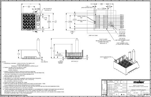
GENERALTOLERANCES(UNLESS SPECIFIED)ANGULAR TOL ±0.5°SERIES MATERIAL NUMBER CUSTOMERGENERAL MARKET76055SEE TABLE4 PLACES ±3 PLACES±2 PLACES ±0.131 PLACE ±0.250 PLACES±DRAFT WHERE APPLICABLEMUST REMAIN WITHIN DIMENSIONSTHIS DRAWING CONTAINS INFORMATION THAT IS PROPRIETARY TO MOLEX ELECTRONIC TECHNOLOGIES, LLC AND SHOULD NOT BE USED WITHOUT WRITTEN PERMISSIONSHEET NUMBER1 OF 3DIMENSION UNITS SCALE MM 4:1DRWN BYDATEMSANDBERG2007/05/24CHK'D BYDATEJLAURX2007/05/24APPR BYDATEJLAURX2010/10/15DOCUMENT NUMBERDOC TYPE DOC PART SD-76055-003PSD001DRAWING SIZETHIRD ANGLE PROJECTIONDIMPACT 5 PAIR HEADERRIGHT GUIDED ASSEMBLY SALES DRAWINGPRODUCT CUSTOMER DRAWINGM I G R A T E D T O N X2017/10/312017/10/312017/11/02167466A B A B U 01C D G G AE C N O :D R W N :C H K 'D :A P P R :J2R E VRELEASE STATUSP1RELEASE DATE 02.11.201708:14:52A B1.90ZZSECTION Z -Z24.8+0.2-0.518.90�2.95�KEY SHOWN IN POSTION "A"14X1.3511.95TAIL LENGTH1.428.620.4MINIMUM BOARD1.00P (PIN LENGTH)±0.20 2.64ROW P ROW O ROW N ROW M ROW L ROW K ROW J ROW H ROW G ROW F ROW E ROW D ROW C ROW B ROW A 8.50B 0.954.751.90PIN A1(ADD FOR END WALL)1.3524.818.9013.212.9514X1.35SIGNAL HOLESREF.GROUND HOLESREF.KEEP OUT ZONESEE PART NUMBER CHARTANDPART NUMBER LOGIC (15 HOLES PER COLUMN)⌖⌀0.10SEE NOTE #7UNPLATED SCREW HOLE3.56±0.08⌀RIGHT GUIDEDBACKPLANE HOLE PATTERN(CONNECTOR SIDE)SEE NOTE 12NOTES:1. MATERIALS: HOUSING - LIQUID CRYSTAL POLYMER (LCP) GLASS-FILLED, UL94V-0TERMINALS - HIGH PERFORMANCE COPPER ALLOY 2. FINISH: 30µ MIN. GOLD IN CONTACT AREA. SELECTIVE TIN ON PCB TAILS. NICKEL OVERALL.3. REFER TO MOLEX PRODUCT SPECIFICATION PS-76060-999FOR PERFORMANCE SPECIFICATIONS AND ADDITIONAL PCB INFORMATION. 4. THIS PART CONFORMS TO CLASS B REQUIREMENTS OF MOLEX COSMETIC SPEC PS-45499-002. 5. PACKAGE PER: PK-70873-759.6. SEE SHEETS 2 & 3 FOR PART NUMBERS AND BOARD RELATIONSHIPS.7. FOR GROUNDED GUIDE PINS USE DIA. 3.56 +/-0.08 (PTH) DIA. 3.66 (DRILL) AND DIA 6.5 (PAD).8. MATES WITH IMPACT DC SERIES NO. 76060.9. KEEP OUT ZONE FOR BP HOUSING LENGTH INCLUDES AN ADDITIONAL 1.0MM TO ACCOMMODATE FOR SPACE REQUIRED BY DC FRONT HOUSING.10. REFER TO MOLEX PCB ROUTING GUIDE AS-76060-990 FOR ANTIPAD AND ROUTING RECOMMENDATIONS. 11. CONNECTORS SUPPLIED WITH A 2-56 UNC-2A SCREW.12. "THESE DIMENSIONS REPRESENT THE AREA NEEDED TO ACCOMMODATE CONNECTOR INSERTION AND REPAIR ON THE PC BOARD. THIS IS REFERRED TO AS THE "CONNECTOR KEEP OUT ZONE" AND DOES NOTREPRESENT THE ACTUAL PERIMETER OF THE CONNECTOR. WHEN LAYING OUT A PC BOARD FOR CONNECTORS STACKED TOGETHER, USE A 1.9mm PROGRESSION."NOTCH DESIGNATESROW A⌖⌀0.15AABBCCDDEEFFGGHHJJKKLLGENERALTOLERANCES(UNLESS SPECIFIED)ANGULAR TOL ±0.5°SERIES MATERIAL NUMBER CUSTOMERGENERAL MARKET76055SEE TABLE4 PLACES ±3 PLACES±2 PLACES ±0.131 PLACE ±0.250 PLACES±DRAFT WHERE APPLICABLEMUST REMAIN WITHIN DIMENSIONSTHIS DRAWING CONTAINS INFORMATION THAT IS PROPRIETARY TO MOLEX ELECTRONIC TECHNOLOGIES, LLC AND SHOULD NOT BE USED WITHOUT WRITTEN PERMISSIONSHEET NUMBER2 OF 3DIMENSION UNITS SCALE MM 4:1DRWN BY DATEMSANDBERG2007/05/24CHK'D BYDATEJLAURX2007/05/24APPR BYDATEJLAURX2010/10/15DOCUMENT NUMBERDOC TYPE DOC PART SD-76055-003PSD001DRAWING SIZETHIRD ANGLE PROJECTIONDIMPACT 5 PAIR HEADERRIGHT GUIDED ASSEMBLY SALES DRAWINGPRODUCT CUSTOMER DRAWINGM I G R A T E D T O N X2017/10/312017/10/312017/11/02167466A B A B U 01C D G G AE C N O :D R W N :C H K 'D :A P P R :J2R E VRELEASE STATUSP1RELEASE DATE 02.11.201708:14:52MATERIAL NUMBER# OF COLUMNS # OF DIFF. PAIR DIM. A DIM. BGUIDE RIGHT OPEN WALL OPTION76055-*1**105025.517.1076055-*2**126029.320.9076055-*7**147033.124.7076055-*6**168036.928.50MATERIAL NUMBER # OF COLUMNS # OF DIFF. PAIR DIM. A DIM. BGUIDE RIGHT END WALL OPTION76055-*1**105026.917.1076055-*2**126030.720.9076055-*7**147034.524.7076055-*6**168038.328.50GUIDE RIGHT END WALL OPTIONGUIDE RIGHT OPEN WALL OPTION76055- 3 = 4.50 (SHORT COMPLIANT, 0.46±0.05 PTH)4 = 4.90 (SHORT COMPLIANT, 0.46±0.05 PTH)5 = 5.50 (SHORT COMPLIANT, 0.46±0.05 PTH)6 = 4.50 (MICRO COMPLIANT, 0.39±0.05 PTH)7 = 4.90 (MICRO COMPLIANT, 0.39±0.05 PTH)8 = 5.50 (MICRO COMPLIANT, 0.39±0.05 PTH)# OF COLUMNS MODULE TYPE5 = GUIDE RIGHT, TIN9 = GUIDE RIGHT END WALL, TINKEY ORIENTATION PIN LENGTH (P)1 = 10 COL2 = 12 COL 6 = 16 COL 7 = 14 COL0 = NO KEY 1 = A 2 = B 3 = C 4 = D 5 = E 6 = F 7 = G 8 = H****PART NUMBER LOGICPART NUMBER TABLEAABBC CDDE EFFGGH HJJKKLLGENERALTOLERANCES(UNLESS SPECIFIED)ANGULAR TOL ±0.5°SERIES MATERIAL NUMBER CUSTOMERGENERAL MARKET76055SEE TABLE4 PLACES ±3 PLACES±2 PLACES ±0.131 PLACE ±0.250 PLACES±DRAFT WHERE APPLICABLEMUST REMAIN WITHIN DIMENSIONSTHIS DRAWING CONTAINS INFORMATION THAT IS PROPRIETARY TO MOLEX ELECTRONIC TECHNOLOGIES, LLC AND SHOULD NOT BE USED WITHOUT WRITTEN PERMISSIONSHEET NUMBER3 OF 3DIMENSION UNITS SCALE MM 4:1DRWN BYDATEMSANDBERG2007/05/24CHK'D BYDATEJLAURX2007/05/24APPR BYDATEJLAURX2010/10/15DOCUMENT NUMBERDOC TYPE DOC PART SD-76055-003PSD001DRAWING SIZETHIRD ANGLE PROJECTIONDIMPACT 5 PAIR HEADERRIGHT GUIDED ASSEMBLY SALES DRAWINGPRODUCT CUSTOMER DRAWINGM I G R A T E D T O N X2017/10/312017/10/312017/11/02167466A B A B U 01C D G G AE C N O :D R W N :C H K 'D :A P P R :J2R E VRELEASE STATUSP1RELEASE DATE 02.11.201708:14:52IMPACT 5 PAIRBOARD RELATIONSHIPSDCARD PCBBPLANE PCBBP ROW ADC HOLE COLUMN (COLUMN 10 REF.)DCARD PCBBPLANE PCBDCARD ROW ABP HOLE COLUMN (COLUMN 10 REF.)0.35OFFSET BETWEEN DC ANDBP HOLE COLUMNS24.83.011.9514.0DCARD ROW AB P R O W AAABBCCD DE EFFG GHHJJKKL L。
EQ-680课件

E Q-680超光子E Q-680t a c h y o n i c p l a t f o r mTHANK YOU苏州澳泰超光子非传统式IPL全面解决皮肤所有问题•永久性脱毛•色素性病变(雀斑、老年斑、日晒损伤等)•痤疮、红血丝、光老化1234高分辨率触摸屏静音高承载万向轮优雅飞鱼手具全金属机身外壳自主研发高性能控制主板不同于一般的商业用料,需要考虑高温、抗潮湿等工作场合需求0102高压隔膜泵/过滤器高压隔膜水泵强劲的功率让水流循环快速的进行,在运行时经过滤器有效拦截水中杂质、颗粒等,让水一直保持清洁干净的状态。
散热器高密度铜制散热器有效断绝了因温度过高而引起的各种问题。
铜在高温条件下仍能保持其形状和强度,也不会有长期老化的现象,铜之所以能有如此优良稳定的性能是由于铜在化学排序中的序位很低,仅高于银、铂、金,性能稳定,不易被腐蚀,不会有杂质溶入水中。
前后发际线、脸部、唇毛、颈部、胳膊、手部、身体、比基尼、腿部、脚部美白嫩肤,收细毛孔、改善肤质增强皮肤弹性雀斑、脂溢性角化病、雀斑样痣等表皮色素性病变及斑点样炎症后色素沉着毛细血管扩张而引起的红血丝DPL特有的窄谱光,可同时产生光热作用和光化学作用,使肌肤里胶原纤维和弹力纤维重新排列,并恢复肌肤弹性,同时增强血管组织功能,改善循环,使肌肤变得光滑、细腻、有弹性。
利用毛干中的黑色素选择性吸收光能量后,将光能转化为热能,热量通过毛干传导至毛囊峡部和毛囊隆突部(毛乳头,毛发生长点),从而破坏毛乳头处的血管使其受热萎缩,从而达到脱毛的效果。
1234有效出光次数高达30万次以上(氙灯使用寿命)采用1200W主电源+600W附电源包含OPT技术+DPL技术聚合传统冰点脱毛的所有优点,强大的功能,不仅可以脱毛还能嫩肤美白,紧致肌肤专利技术术前清洁:将脸上妆容清洁干净,使用小气泡或焕氧大气泡均可,凝胶涂抹均匀一毛钱硬币的厚度即可。
调节仪器参数,治疗头酒精擦拭消毒,垂直贴紧压实,定点操作,光斑3/1叠加、横竖交替、全脸治疗,避开毛发及黑痣类。
- 1、下载文档前请自行甄别文档内容的完整性,平台不提供额外的编辑、内容补充、找答案等附加服务。
- 2、"仅部分预览"的文档,不可在线预览部分如存在完整性等问题,可反馈申请退款(可完整预览的文档不适用该条件!)。
- 3、如文档侵犯您的权益,请联系客服反馈,我们会尽快为您处理(人工客服工作时间:9:00-18:30)。
This specification document applies to R/D(Resolver/Digital) Conversion IC which is mountable on vehicles(automobiles, trains and so on), uses the time-proven R/D Conversion method “Digital Tracking Method” and provides a low-cost and reliable angle(absolute value) detection system designed to accompany with amplitude modulation method brushless resolver(BRX).
Figure 1 Function Configuration Diagram
参考図
ED’N No.
DWG NO.
3
4
5
6
78
9
10
11 12 SHEET
SPC 0 0 9 5 7 4W00 3
T A M A G A W A S E IK I C O . , L T D . J A P参A考N図
参考図 村松 重利 2015/04/13 23:30:38 JST
MODEL No. AU6805
ED’N No. . .
TITLE Smartcoder(AU6805)
Specifications
DWG NO.
34
5
67
8
9 10 11 12 SHEET
SPC009574W00 1 39
T A M A G A W A S E IK I C O . , L T D . J A P参A考N 図
3.2 Physical Feature ································································································31 3.3 Environment Resistance ·······················································································31 4 Quality Assurance ····································································································31 4.1 Warranty of Products···························································································31 4.2 Reliability Test··································································································32 5 Application Note······································································································33 5.1 Input/Output Interface Circuit ················································································33 5.2 System Setting(IC Operating Environment Equipment) ··················································33 5.3 Measure against Noise ·························································································34 5.4 Fail-safe System Architecture ················································································35 5.5 Encoder Application ···························································································36
3.1.2 Functional Composition
R/D conversion functional composition of Digital Tracking Method refers to Figure 1 Function Configuration Diagram.
Sinθ/F(t) BRX
2 Related Document (Referential Drawing)
Attended Figure.3 AU6805 Package Outline Figure
3 Requirements
3.1 Function and Performances
3.1.1 Concept/Feature
θ
R/D Conversion Core
φ
(Digital Tracking Method)
Cosθ/F(t)
F(t)
Excitation Signal
System Control / Input Output Control
Generation
Failure Detection / Built In Self Test(BIST)
The internal constitution of Digital Tracking R/D conversion IC is shown in Figure 2.
VCC
参考図
ED’N No.
DWG NO.
3
4
5
6
78
9
10
11 12 SHEET
SPC 0 0 9 5 7 4W00 2
T A M A G A W A S E IK I C O . , L T D . J A P参A考N図
参考図 村松 重利 2015/04/13 23:30:38 JST
参考図
1 Scope
Digital Tracking Method consists of Digital Signal Processing hardware, sustains and improves the conversion performance (resolution, accuracy, tracking speed, noise immunity, etc.) which is equivalent of AU6803 Twin-PLL method, and achieve a low price. Capable of building an absolute angle detection system with safety and high reliability by enhancing the failure detection function and incorporating a built-in self-test (BIST) function for the R/D conversion and a failure detection function. Simple to use. (All-in-one design; eliminates phase adjustment of exciting signal (i.e. allowable phase angle: ±45 degrees), and others). Quality capable of enduring vehicle-mount applications.